WO2023079594A1 - 経路提示装置、経路提示方法、およびプログラム - Google Patents
経路提示装置、経路提示方法、およびプログラム Download PDFInfo
- Publication number
- WO2023079594A1 WO2023079594A1 PCT/JP2021/040404 JP2021040404W WO2023079594A1 WO 2023079594 A1 WO2023079594 A1 WO 2023079594A1 JP 2021040404 W JP2021040404 W JP 2021040404W WO 2023079594 A1 WO2023079594 A1 WO 2023079594A1
- Authority
- WO
- WIPO (PCT)
- Prior art keywords
- route
- information
- user
- presentation device
- required time
- Prior art date
- Legal status (The legal status is an assumption and is not a legal conclusion. Google has not performed a legal analysis and makes no representation as to the accuracy of the status listed.)
- Ceased
Links
Images



Classifications
-
- G—PHYSICS
- G01—MEASURING; TESTING
- G01C—MEASURING DISTANCES, LEVELS OR BEARINGS; SURVEYING; NAVIGATION; GYROSCOPIC INSTRUMENTS; PHOTOGRAMMETRY OR VIDEOGRAMMETRY
- G01C21/00—Navigation; Navigational instruments not provided for in groups G01C1/00 - G01C19/00
- G01C21/26—Navigation; Navigational instruments not provided for in groups G01C1/00 - G01C19/00 specially adapted for navigation in a road network
-
- G—PHYSICS
- G01—MEASURING; TESTING
- G01C—MEASURING DISTANCES, LEVELS OR BEARINGS; SURVEYING; NAVIGATION; GYROSCOPIC INSTRUMENTS; PHOTOGRAMMETRY OR VIDEOGRAMMETRY
- G01C21/00—Navigation; Navigational instruments not provided for in groups G01C1/00 - G01C19/00
- G01C21/26—Navigation; Navigational instruments not provided for in groups G01C1/00 - G01C19/00 specially adapted for navigation in a road network
- G01C21/34—Route searching; Route guidance
Definitions
- the present invention relates to a route presentation device, a route presentation method, and a program.
- Non-Patent Document 1 “Guidelines for Evacuation Information” (Non-Patent Document 1) established by the Cabinet Office, disaster prevention information such as evacuation information and disaster prevention weather information is provided so that residents can understand various information sent by the Meteorological Agency and local governments. is to be provided using five “alert levels”.
- an application related to disaster prevention has a function to search for places such as shelters or public facilities on a disaster prevention map in advance and display the altitude from the current position in a graph, or a function to share information among users. , evacuation routes, and other information for users to evacuate safely.
- Patent Document 1 As an existing technology related to route information, GPS data is used to estimate the location and route where the user will stay in the future, and the position that the user passes through is represented by a probability distribution for each small area, making it possible to estimate the action route with high accuracy. It is known to do (Patent Document 1). There is also a known technology that can perform an appropriate route search according to the means of transportation even if the traffic conditions (accessibility information) assigned to links on a geographic network include uninvestigated links. (Patent document 2).
- the user selects an evacuation site, and the result of searching for the route from the current location to the evacuation site is displayed on the map.
- the required time to the destination is displayed on the map, it is the time calculated according to the walking speed of a healthy person, not the time according to the user's condition (age, health condition, etc.). is not. Therefore, when evacuating from a tsunami, for example, the user cannot grasp the height of the reaching tsunami, and therefore does not know whether the selected evacuation site is in a safe place. Furthermore, since the user himself/herself does not know the exact required time to arrive at the evacuation site, he/she cannot judge whether or not he/she will arrive at the evacuation site by the arrival time of the tsunami.
- Patent Document 1 does not have the function of displaying the route from the current position to the destination according to the characteristics of the user's body.
- Patent Document 2 if there is accessibility information, it is possible to select a route according to the user's physical condition, but time is not taken into consideration. Therefore, when evacuating according to the presented information, there is a possibility that the evacuation will not be completed in time. For example, if you are walking through the relevant place within the tsunami arrival time, you will not be able to evacuate in time.
- the present invention has been made in view of the above, and aims to present a suitable route to the user.
- a route presentation device includes: a user state accumulation unit storing information indicating a user state; a route search unit searching for at least one or more routes to a destination; A required time calculation unit for calculating the required time according to the user's condition, and a search result display unit for displaying the route and the required time for the route on a map.
- a route presentation method includes a computer that searches for at least one or more routes to a destination, calculates the required time for each of the routes according to the state of the user, Display the required time of the route on the map.
- a suitable route can be presented to the user.
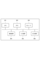
- FIG. 1 is a functional block diagram showing an example of the configuration of the route presentation device of this embodiment.
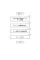
- FIG. 2 is a flow chart showing an example of the flow of processing of the route presentation device.
- FIG. 3 is a diagram showing an example of a display screen presenting a route for people with weak legs.
- FIG. 4 shows an example of a display screen presenting a route for energetic people.
- FIG. 5 is a diagram illustrating an example of a hardware configuration of a route presentation device;
- a route presentation device 1 of the present embodiment will be described with reference to FIG.
- the route presentation device 1 and the client terminal 5 are connected via a network.
- the client terminal 5 is a terminal used by a user, and can be, for example, a personal computer, a tablet terminal, or a mobile terminal.
- the route presentation device 1 presents the route to the destination and the time required for each route according to the user.
- a general computer having a storage device 10, a processing device 20, and an input/output interface 30 can be used for the route presentation device 1 shown in FIG.
- the computer executes the program to function as each part of the route presentation device 1 shown in FIG.
- the storage device 10 can use Read Only Memory (ROM), Random Access Memory (RAM), hard disk drive (HDD), solid state drive (SSD), and the like.
- ROM Read Only Memory
- RAM Random Access Memory
- HDD hard disk drive
- SSD solid state drive
- the storage device 10 stores various data such as input data, output data, and intermediate data necessary for the processing device 20 to execute processing.
- the processing device 20 is a central processing unit (CPU) or a graphics processing unit (GPU) in order to function as the route presentation device 1, and reads out data stored in the storage device 10 and writes data to the storage device 10. and input/output data to/from the input/output interface 30 .
- CPU central processing unit
- GPU graphics processing unit
- the input/output interface 30 inputs a request from the client terminal 5 received via the network to the processing device 20, and transmits the processing result of the processing device 20 to the client terminal 5 via the network. Also, the input/output interface 30 receives various information via the network and inputs the information to the processing device 20 .
- the storage device 10 includes a user information storage unit 11, a user state storage unit 12, a map information storage unit 13, a weather-related information storage unit 14, and a basic information storage unit 15.
- the user information accumulation unit 11 accumulates user information regarding users who use the client terminal 5 .
- the user information includes, for example, basic user information such as the user's name, date of birth, gender, and address, and optional information for obtaining the walking speed of the user.
- the optional information includes information on the number of steps obtained from a pedometer or a step counting application, results of a physical fitness test, and the like.
- the step count information is, for example, the number of steps per day, walking time, or walking speed.
- the result of the physical fitness test is used as reference information when the walking speed of the user is not accumulated.
- the user state accumulation unit 12 accumulates information about the user's current state.
- the user's state includes, for example, the user's location information and current walking speed.
- the user's status may include the user's health status.
- the map information storage unit 13 stores map-related information.
- the map-related information includes, for example, map information including information necessary for searching for a route, altitude data, disaster prevention facility information, and disaster prediction information.
- the disaster prevention equipment information is, for example, information on shelters, evacuation sites, water supply bases, medical institutions, toilets, or barrier-free information.
- the disaster prediction information is, for example, various hazard maps, tsunami height, impact start time, or tsunami arrival time.
- the weather-related information accumulation unit 14 accumulates weather information or disaster information.
- the weather information is, for example, the user's current location, information about the current weather at the destination, or information about future weather forecasts.
- Disaster information includes, for example, various warnings, the arrival time and height of a tsunami when a tsunami occurs, river water level information when a typhoon hits, emergency earthquake warnings, and disaster-related information issued by local governments. be.
- the basic information accumulation unit 15 contains basic information for calculating the time required for moving a route according to the user.
- the basic information includes, for example, walking speed, stride length information, and step reduction rate at inclination angle by age group, age group, or gender.
- the basic information is input to the basic information storage unit 15 in advance when operating the system.
- the processing device 20 includes a user information processing section 21, a user state grasping section 22, a map information creating section 23, a weather-related information collecting section 24, a route searching section 25, a required time calculating section 26, and a search result displaying section 27.
- the user information processing section 21 receives input of user basic information and option information and stores them in the user information storage section 11 . If the option information is not input, the user information processing unit 21 refers to the basic information stored in the basic information storage unit 15, specifies the user's walking speed or stride information based on the user basic information, and determines the walking speed. Alternatively, stride information may be stored in the user information storage unit 11 .
- the user state grasping unit 22 receives information indicating the state of the user from the client terminal 5 during normal times such as when the user is moving, and stores the information in the user state accumulation unit 12 .
- the information indicating the user's state is, for example, the user's position information, walking speed, or stride information.
- Location information can be obtained using geolocation technology.
- the location information may be acquired from a device such as GPS provided in the client terminal 5, or information from a Wi-Fi access point or base station may be used. If the location information cannot be obtained, the user's current location may be specified by directly inputting a place name, selection on a map, landmark information, or the like.
- Walking speed and step length information may be calculated using information obtained from a pedometer. For example, walking speed can be calculated by dividing the moving distance by the moving time when walking continuously for a specified time or more.
- the map information creation unit 23 collects map-related information and stores it in the map information accumulation unit 13 . Also, the map information creation unit 23 creates a map including a route from the user's current position to the destination. The map information creation unit 23 may divide the disaster prevention equipment information or the disaster prediction information stored in the map information storage unit 13 into layers and arrange them on the map.
- the weather-related information collection unit 24 collects weather information or disaster information based on the user's current location and stores it in the weather-related information storage unit 14 .
- the weather-related information collection unit 24 collects weather information or disaster information on the route specified in the route search, disaster information on areas including evacuation sites within a certain range including the current position, or the destination to which the user is heading. It collects disaster information of areas within a certain range including the disaster information and stores it in the weather-related information accumulation unit 14 .
- the weather-related information collecting unit 24 may collect not only current weather information or disaster information, but also past to present and future future weather information or disaster information, and store the collected information in the weather-related information storage unit 14 .
- the route search unit 25 Upon receiving a route search request from the client terminal 5, the route search unit 25 uses the map information stored in the map information storage unit 13 to search for a route to the destination. For example, when the route search request is a route search for evacuation, the route search unit 25 retrieves the disaster prevention equipment information stored in the map information storage unit 13 based on the user's location information stored in the user state storage unit 12. , a suitable evacuation site for the user is searched for as a destination, and a route from the user's current position to the destination is searched. When extracting the destination, the route search unit 25 raises the priority of places within the living area where evacuation is possible based on the walking history of the user.
- the information on the barrier-free map is used to search for a route to an evacuation shelter according to the user's situation. For example, information such as the presence or absence of toilets, elevators, slopes, and Braille blocks is used.
- the route search request may include disaster information that caused evacuation, such as heavy rain, earthquake, or tsunami.
- the route search unit 25 searches for destinations and routes according to disaster information. For example, when a tsunami occurs, the route search unit 25 sets an evacuation site on high ground where the tsunami does not reach as the destination. If a departure position and a destination are specified in the route search request, the route search unit 25 may search for a route from the departure position to the destination.
- the route search unit 25 obtains the inclination angle of the road on the route from the difference in elevation, associates it with the route as route-related information, and transmits it to the required time calculation unit 26 .
- the route search unit 25 may use the operation information of the transportation to search for the route.
- the required time calculation unit 26 calculates the required time to the destination for each route searched by the route search unit 25, taking into account the user's condition. Specifically, the required time calculation unit 26 corrects the walking speed by multiplying the walking speed stored in the user information accumulation unit 11 or the user state accumulation unit 12 by the reduction rate obtained from the inclination angle on the route, The time required to reach the destination is calculated using the corrected walking speed.
- the required time calculation unit 26 may preferentially use the walking speed stored in the user state accumulation unit 12 . For example, if the walking speed is stored in the user state accumulation unit 12, the walking speed stored in the user state accumulation unit 12 is used. The walking speed stored in section 11 is used.
- the required time calculation unit 26 may calculate the required time using stride length information instead of the walking speed.
- the required time calculation unit 26 reads the reduction rate according to the tilt angle from the basic information storage unit 15 and applies it to the walking speed. The greater the tilt angle, the greater the reduction rate. It is assumed that there is no change in walking speed on downhills.
- the required time calculation unit 26 obtains the required time TR( k) of the route R(k) by the following equation (1). k represents the identification number of the route.
- the required time calculation unit 26 may determine the priority of routes. For example, the required time calculation unit 26 determines the route priority based on whether the route is difficult to walk, whether the route passes through a caution level area, and whether the route passes through an area where disasters have occurred in the past. decide. Specifically, the route priority is determined by the following process.
- the required time calculation unit 26 obtains an expected value E R(k) (inclination) of the walking difficulty of the route R(k) using the following equation (2).
- d R(k) represents the total distance of the route R(k).
- the required time calculation unit 26 calculates the expected value E R(k) (encounter) of encountering a disaster on the route R(k) using the following equation (3).
- i represents the number of alert level areas
- the required time calculation unit 26 calculates the expected value ER(k)(disaster) of the past disaster occurrence point of the route R(k) by the following equation (4) based on the past disaster occurrence point.
- j represents the number of disaster occurrence areas
- the required time calculation unit 26 uses each expected value obtained for the route R(k) to obtain PR (k) by the following equation (5), and the obtained PR (k) values are calculated in descending order. Prioritize.
- ⁇ , ⁇ , ⁇ are weighting coefficients for each expected value.
- the required time calculation unit 26 transmits route information and required time to the search result display unit 27 .
- the route information may include information such as slopes on the route and priority.
- the search result display unit 27 displays the searched route and the required time for each route on a map, and returns to the client terminal 5 a display screen on which various information such as weather information or disaster information is superimposed.
- various information to be superimposed can be designated by the user.
- the user may specify the time zone.
- basic information including walking speed, stride length information, and the rate of decrease in the number of steps at an angle of inclination is stored in the basic information storage unit 15 for each age, age, and sex.
- user basic information and option information are stored in the user information storage unit 11 for each user.
- the user state grasping unit 22 receives information about the state of the user from the client terminal 5, and determines the location information of the user, the number of steps taken during a certain period of time at the present time, and the distance traveled during a certain period of time at the present time. , and the current walking speed are stored in the user state accumulation unit 12 .
- the map information creation unit 23 collects map information, disaster prevention equipment information, and disaster prediction information as necessary, and stores them in the map information accumulation unit 13 .
- the weather-related information collection unit 24 collects weather information and disaster information according to the user's location information, and stores them in the weather-related information accumulation unit 14 .
- the client terminal 5 When a disaster occurs, the client terminal 5 notifies the user that evacuation is necessary and inquires whether it is necessary to search for a route to an evacuation center. For example, the client terminal 5 displays a route search button on the screen. When the user presses the route search button, the client terminal 5 transmits a route search request to the route presentation device 1 . The route presentation device 1 receives the route search request and executes the processing shown in the flowchart of FIG.
- the route search unit 25 searches for a route from the current position to the destination. Specifically, the route search unit 25 acquires the user's current position from the user state storage unit 12, acquires information about the user from the user information storage unit 11 and the user state storage unit 12, and obtains disaster prevention facility information and disaster prediction. Information is acquired from the map information accumulation unit 13 and a destination suitable for the user is extracted. The route search unit 25 may extract multiple destinations. The route search unit 25 refers to the map information storage unit 13 and searches for a route from the current position to the destination. If the route search request includes the departure point, destination, and desired arrival time, the route search unit 25 searches for a route from the departure point to the destination.
- the required time calculation unit 26 calculates the required time for each searched route. Specifically, the required time calculation unit 26 acquires the walking speed of the user from the user state accumulation unit 12 . When the walking speed is not stored in the user state accumulation unit 12 , the required time calculation unit 26 acquires the user's walking speed from the user information accumulation unit 11 . The required time calculation unit 26 may acquire stride information from the user information storage unit 11 or the user state storage unit 12 . The required time calculation unit 26 obtains the required time for each route from the route distance and the user's walking speed or step length information, further calculates the rate of decrease in walking speed or step length from the inclination angle on each route, and calculates the slope portion. Add time to the required time that increases with distance and rate of decrease.
- the search result display unit 27 acquires various information about the route. For example, the search result display unit 27 acquires weather information or disaster information for an area including the current position and the destination from the weather-related information accumulation unit 14 . The search result display unit 27 may acquire past or future information.
- step S14 the search result display unit 27 displays each route on the map along with the required time, and causes the client terminal 5 to display a screen on which various information acquired in step S13 is superimposed.
- FIG. 3 is an example of a display screen presenting a route for people with weak legs
- FIG. 4 is an example of a display screen presenting a route for energetic people.
- the display screen 100 of FIGS. 3 and 4 includes a map display area 110, a message display area 120, a display information selection area 130, and a slide bar 140.
- the screen configuration is an example, and is not limited to this.
- a map including the user's current position and destination, the route searched by the route presentation device 1, and various information are superimposed and displayed.
- a map layer, a route search result layer, a weather/disaster information layer, a past disaster information layer, and a hazard map layer are superimposed and displayed.
- a map and disaster prevention equipment information are displayed on the map layer.
- the route search results layer displays the user's current location, destination, and route search results.
- the route search result layer may display the required time for each route and information on caution points (such as slope information) on the route.
- the weather/disaster information layer displays weather information including forecasts and disaster information (advisories and warnings).
- the past disaster information layer displays past disaster information (sites of landslides, flooded areas, etc.).
- the hazard map layer displays the hazard maps issued by each local government. There are multiple types of hazard maps, such as floods, inland waters, reservoirs, storm surges, tsunamis, landslides, volcanoes, and earthquakes, so the appropriate one is displayed according to the disaster.
- the above layers are examples, and are not limited to these. It should be noted that the display of each layer may be turned on and off.
- the map displayed in the map display area 110 may be enlarged or reduced according to the user's operation.
- route A, route B, and route C are displayed with the required time
- route X, route Y, and route Z are displayed with the required time
- Route A, route B, and route C in FIG. 3 correspond to route Y, route Z, and route X in FIG. 4, respectively.
- route C which is the third candidate in FIG. 3, is presented as the first candidate (route X).
- the map display area 110 also displays required time and slope information for each route. The slopes on the route may be displayed in an easy-to-understand manner by changing the display mode.
- a warning message and a description of the route are displayed in the message display area 120.
- the warning message displays current warnings, advisories, or disaster information.
- the route description describes each route in order of priority. For example, information on uphills on the route, road visibility, information on landmarks for turning corners, and the like are described.
- Route A which is long but has gentle uphill slopes, is the first candidate.
- Route B which has no traffic lights at intersections and includes a rather steep uphill, is presented as the second candidate.
- Route X which is straight and has good visibility
- Route Y and route Z take the same amount of time, but since route Z must pass through intersections without traffic lights, considering the safety of the route, the gently uphill route Y is presented as the second candidate. are doing.
- check boxes for selecting various types of information to be superimposed and displayed on the map display area 110 are arranged. By turning on/off a check box, display of the corresponding layer in the map display area 110 is turned on/off.
- the slide bar 140 is used to specify the time of various information to be displayed in the map display area 110. For example, if the slide bar 140 is shifted to the left, the weather conditions before the reference time (for example, the current time or the estimated time of arrival) are displayed in the map display area 110 . When the slide bar 140 is shifted to the right, predicted weather conditions are displayed.
- the route presentation device 1 of this embodiment includes the user state storage unit 12 storing information indicating the user's state, and the route search unit 25 searching for at least one or more routes to the destination. , a required time calculation unit 26 for calculating the required time according to the user's condition for each route, and a search result display unit 27 for displaying the route and the required time for the route on a map. As a result, it is possible to present a route that considers the user's condition.
- the required time calculation unit 26 calculates the required time for each route using the walking speed or stride length based on the user's state, and further calculates the walking speed according to the inclination angle on the route. Alternatively, the required time is calculated by reducing the stride length. This makes it possible to present a route that is more suitable for the user's condition.
- the required time calculation unit 26 prioritizes the route based on the difficulty of walking the route, the possibility of encountering disasters along the route, and the past disaster occurrence situation along the route. attach. This will give you a safer route.
- the route presentation device 1 of the present embodiment does not take into account the user's condition, the weather information or weather forecast for the time zone in which the user travels to the destination, and past disaster information. Can suggest a safe route.
- the route presentation device 1 described above includes, for example, a central processing unit (CPU) 901, a memory 902, a storage 903, a communication device 904, an input device 905, and an output device 906 as shown in FIG. and a general-purpose computer system can be used.
- the CPU 901 executes a predetermined program loaded on the memory 902 to implement the route presentation device 1 .
- This program can be recorded on a computer-readable recording medium such as a magnetic disk, optical disk, or semiconductor memory, or distributed via a network.
Landscapes
- Engineering & Computer Science (AREA)
- Radar, Positioning & Navigation (AREA)
- Remote Sensing (AREA)
- Automation & Control Theory (AREA)
- Physics & Mathematics (AREA)
- General Physics & Mathematics (AREA)
- Navigation (AREA)
Priority Applications (2)
| Application Number | Priority Date | Filing Date | Title |
|---|---|---|---|
| JP2023557862A JPWO2023079594A1 (https=) | 2021-11-02 | 2021-11-02 | |
| PCT/JP2021/040404 WO2023079594A1 (ja) | 2021-11-02 | 2021-11-02 | 経路提示装置、経路提示方法、およびプログラム |
Applications Claiming Priority (1)
| Application Number | Priority Date | Filing Date | Title |
|---|---|---|---|
| PCT/JP2021/040404 WO2023079594A1 (ja) | 2021-11-02 | 2021-11-02 | 経路提示装置、経路提示方法、およびプログラム |
Publications (1)
| Publication Number | Publication Date |
|---|---|
| WO2023079594A1 true WO2023079594A1 (ja) | 2023-05-11 |
Family
ID=86240786
Family Applications (1)
| Application Number | Title | Priority Date | Filing Date |
|---|---|---|---|
| PCT/JP2021/040404 Ceased WO2023079594A1 (ja) | 2021-11-02 | 2021-11-02 | 経路提示装置、経路提示方法、およびプログラム |
Country Status (2)
| Country | Link |
|---|---|
| JP (1) | JPWO2023079594A1 (https=) |
| WO (1) | WO2023079594A1 (https=) |
Cited By (1)
| Publication number | Priority date | Publication date | Assignee | Title |
|---|---|---|---|---|
| US20230150362A1 (en) * | 2021-11-12 | 2023-05-18 | Toyota Jidosha Kabushiki Kaisha | Vehicle display device, vehicle, vehicle display system, vehicle display method, and non-transitory computer-readable medium |
Citations (4)
| Publication number | Priority date | Publication date | Assignee | Title |
|---|---|---|---|---|
| JP2012252614A (ja) * | 2011-06-04 | 2012-12-20 | Ism Corp | 津波避難ナビゲーションシステム、その方法及びプログラム |
| JP2016161378A (ja) * | 2015-03-02 | 2016-09-05 | セイコーエプソン株式会社 | 電子機器、計算方法、及びプログラム |
| JP2016224755A (ja) * | 2015-06-01 | 2016-12-28 | 富士通株式会社 | 避難誘導プログラム、避難誘導方法、移動端末装置、及び避難支援プログラム |
| JP2021092393A (ja) * | 2019-12-06 | 2021-06-17 | フォルシアクラリオン・エレクトロニクス株式会社 | 情報処理装置、降車地点算出システム、降車地点算出方法およびプログラム |
Family Cites Families (3)
| Publication number | Priority date | Publication date | Assignee | Title |
|---|---|---|---|---|
| JP5768324B2 (ja) * | 2010-03-31 | 2015-08-26 | 富士通株式会社 | 災害情報処理装置 |
| JP2013089224A (ja) * | 2012-03-26 | 2013-05-13 | Ism Corp | 津波避難支援システム、津波避難支援方法、津波避難支援装置およびその制御方法と制御プログラム |
| JP6619714B2 (ja) * | 2016-09-15 | 2019-12-11 | 株式会社日立製作所 | 避難誘導情報提供装置および避難誘導情報提供方法 |
-
2021
- 2021-11-02 WO PCT/JP2021/040404 patent/WO2023079594A1/ja not_active Ceased
- 2021-11-02 JP JP2023557862A patent/JPWO2023079594A1/ja active Pending
Patent Citations (4)
| Publication number | Priority date | Publication date | Assignee | Title |
|---|---|---|---|---|
| JP2012252614A (ja) * | 2011-06-04 | 2012-12-20 | Ism Corp | 津波避難ナビゲーションシステム、その方法及びプログラム |
| JP2016161378A (ja) * | 2015-03-02 | 2016-09-05 | セイコーエプソン株式会社 | 電子機器、計算方法、及びプログラム |
| JP2016224755A (ja) * | 2015-06-01 | 2016-12-28 | 富士通株式会社 | 避難誘導プログラム、避難誘導方法、移動端末装置、及び避難支援プログラム |
| JP2021092393A (ja) * | 2019-12-06 | 2021-06-17 | フォルシアクラリオン・エレクトロニクス株式会社 | 情報処理装置、降車地点算出システム、降車地点算出方法およびプログラム |
Cited By (1)
| Publication number | Priority date | Publication date | Assignee | Title |
|---|---|---|---|---|
| US20230150362A1 (en) * | 2021-11-12 | 2023-05-18 | Toyota Jidosha Kabushiki Kaisha | Vehicle display device, vehicle, vehicle display system, vehicle display method, and non-transitory computer-readable medium |
Also Published As
| Publication number | Publication date |
|---|---|
| JPWO2023079594A1 (https=) | 2023-05-11 |
Similar Documents
| Publication | Publication Date | Title |
|---|---|---|
| JP6619714B2 (ja) | 避難誘導情報提供装置および避難誘導情報提供方法 | |
| JP5686479B2 (ja) | 避難ルート出力装置、避難ルート出力方法、及びプログラム | |
| Wang et al. | A novel agent-based model for tsunami evacuation simulation and risk assessment | |
| JP2003168179A (ja) | リアルタイムハザードマップシステム | |
| JP4082686B2 (ja) | リアルタイム動的氾濫シミュレーションシステム | |
| US20150160024A1 (en) | Ranking of Path Segments Based on Incident Probability | |
| JP7536413B2 (ja) | 地図表示装置、地図表示装置の制御方法、および地図表示プログラム | |
| JP2013089224A (ja) | 津波避難支援システム、津波避難支援方法、津波避難支援装置およびその制御方法と制御プログラム | |
| JP4409904B2 (ja) | 経路情報提供システムおよび経路情報提供方法 | |
| Péroche et al. | An accessibility graph-based model to optimize tsunami evacuation sites and routes in Martinique, France | |
| JP2004037269A (ja) | 自立移動支援システム、その方法および記録媒体 | |
| KR101858181B1 (ko) | 서베이(조망)형 내비게이션 시스템 | |
| JP6945755B1 (ja) | 解析装置および解析方法 | |
| JP2016224755A (ja) | 避難誘導プログラム、避難誘導方法、移動端末装置、及び避難支援プログラム | |
| WO2023079594A1 (ja) | 経路提示装置、経路提示方法、およびプログラム | |
| JP2020061005A (ja) | 避難行動支援システム | |
| JP6915015B2 (ja) | 提供装置、提供方法及び提供プログラム | |
| KR102648502B1 (ko) | 재난 및 재해 시 위험지역 우회 대피경로를 제공하는 안전대피로 제공장치 | |
| JP2005050236A (ja) | 土砂災害情報処理装置およびそれを用いる土砂災害情報の提供方法 | |
| JP7111397B1 (ja) | プログラム、方法及び情報処理装置 | |
| JP2006145705A (ja) | 災害予測装置 | |
| JP2023102161A (ja) | 提示装置、提示方法及び提示プログラム | |
| JP2022119645A (ja) | 避難所管理プログラム、装置、及び方法 | |
| KR20180101866A (ko) | 기상에 따른 도로구간 위험도의 지도 표출 방법, 이를 수행하는 지도 서비스 시스템, 및 이에 사용되는 웹서버 | |
| JP7854411B2 (ja) | 避難情報提示装置および避難情報提示方法 |
Legal Events
| Date | Code | Title | Description |
|---|---|---|---|
| 121 | Ep: the epo has been informed by wipo that ep was designated in this application |
Ref document number: 21963192 Country of ref document: EP Kind code of ref document: A1 |
|
| ENP | Entry into the national phase |
Ref document number: 2023557862 Country of ref document: JP Kind code of ref document: A |
|
| WWE | Wipo information: entry into national phase |
Ref document number: 18703777 Country of ref document: US |
|
| NENP | Non-entry into the national phase |
Ref country code: DE |
|
| 122 | Ep: pct application non-entry in european phase |
Ref document number: 21963192 Country of ref document: EP Kind code of ref document: A1 |