WO2023074155A1 - 軸受装置、及び回転機械 - Google Patents
軸受装置、及び回転機械 Download PDFInfo
- Publication number
- WO2023074155A1 WO2023074155A1 PCT/JP2022/034051 JP2022034051W WO2023074155A1 WO 2023074155 A1 WO2023074155 A1 WO 2023074155A1 JP 2022034051 W JP2022034051 W JP 2022034051W WO 2023074155 A1 WO2023074155 A1 WO 2023074155A1
- Authority
- WO
- WIPO (PCT)
- Prior art keywords
- bearing
- rotating shaft
- support ring
- bearing device
- support
- Prior art date
- Legal status (The legal status is an assumption and is not a legal conclusion. Google has not performed a legal analysis and makes no representation as to the accuracy of the status listed.)
- Ceased
Links
Images


Classifications
-
- F—MECHANICAL ENGINEERING; LIGHTING; HEATING; WEAPONS; BLASTING
- F16—ENGINEERING ELEMENTS AND UNITS; GENERAL MEASURES FOR PRODUCING AND MAINTAINING EFFECTIVE FUNCTIONING OF MACHINES OR INSTALLATIONS; THERMAL INSULATION IN GENERAL
- F16C—SHAFTS; FLEXIBLE SHAFTS; ELEMENTS OR CRANKSHAFT MECHANISMS; ROTARY BODIES OTHER THAN GEARING ELEMENTS; BEARINGS
- F16C35/00—Rigid support of bearing units; Housings, e.g. caps, covers
- F16C35/02—Rigid support of bearing units; Housings, e.g. caps, covers in the case of sliding-contact bearings
-
- F—MECHANICAL ENGINEERING; LIGHTING; HEATING; WEAPONS; BLASTING
- F16—ENGINEERING ELEMENTS AND UNITS; GENERAL MEASURES FOR PRODUCING AND MAINTAINING EFFECTIVE FUNCTIONING OF MACHINES OR INSTALLATIONS; THERMAL INSULATION IN GENERAL
- F16C—SHAFTS; FLEXIBLE SHAFTS; ELEMENTS OR CRANKSHAFT MECHANISMS; ROTARY BODIES OTHER THAN GEARING ELEMENTS; BEARINGS
- F16C17/00—Sliding-contact bearings for exclusively rotary movement
- F16C17/02—Sliding-contact bearings for exclusively rotary movement for radial load only
- F16C17/03—Sliding-contact bearings for exclusively rotary movement for radial load only with tiltably-supported segments, e.g. Michell bearings
-
- F—MECHANICAL ENGINEERING; LIGHTING; HEATING; WEAPONS; BLASTING
- F16—ENGINEERING ELEMENTS AND UNITS; GENERAL MEASURES FOR PRODUCING AND MAINTAINING EFFECTIVE FUNCTIONING OF MACHINES OR INSTALLATIONS; THERMAL INSULATION IN GENERAL
- F16C—SHAFTS; FLEXIBLE SHAFTS; ELEMENTS OR CRANKSHAFT MECHANISMS; ROTARY BODIES OTHER THAN GEARING ELEMENTS; BEARINGS
- F16C23/00—Bearings for exclusively rotary movement adjustable for aligning or positioning
- F16C23/02—Sliding-contact bearings
- F16C23/04—Sliding-contact bearings self-adjusting
Definitions
- the present disclosure relates to bearing assemblies and rotating machines. This application claims priority to Japanese Patent Application No. 2021-177357 filed in Japan on October 29, 2021, the content of which is incorporated herein.
- rotating machines including gas turbines and steam turbines are provided with bearing devices for rotatably supporting a rotating shaft.
- a journal bearing that supports the radial load of the rotating shaft and a thrust bearing that supports the axial (central axis) direction load of the rotating shaft are used.
- Patent Document 1 the one described in Patent Document 1 below is known as an example of the journal bearing.
- the device disclosed in Patent Document 1 below includes a cylindrical support ring (support ring) that covers the bearing body from the outer peripheral side, and a bearing box (bearing casing) that supports the support ring from below.
- the bearing housing abuts from below on a pair of flange portions projecting from the outer peripheral surface of the support ring to both sides in the horizontal direction with respect to the axis.
- the present disclosure has been made to solve the above problems, and aims to provide a bearing device and a rotating machine that can more stably support a rotating shaft.
- a bearing device that supports a rotating shaft rotatable about an axis extending in a horizontal direction, comprising: a bearing body that supports the rotating shaft; a support ring body covering from the outer peripheral side, a support ring provided integrally with the support ring body and having a pedestal portion having a bottom surface facing downward, and a support provided separately from the support ring and abutting on the bottom surface a bearing housing having a surface, wherein the bearing main body is directly or indirectly supported by a ring portion that covers the rotating shaft from the outer peripheral side, and an inner peripheral surface of the ring portion; When viewed from the axial direction, the support surface extends at least on an extension of a straight line connecting the axial line and the center of the lower pad in the circumferential direction. .
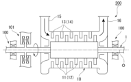
- FIG. 1 is a schematic diagram showing a configuration of a rotating machine (steam turbine) according to an embodiment of the present disclosure
- FIG. 1 is a cross-sectional view showing the configuration of a bearing device according to an embodiment of the present disclosure
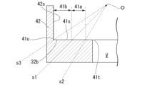
- FIG. 1 is an enlarged cross-sectional view of a main part of a bearing device according to an embodiment of the present disclosure
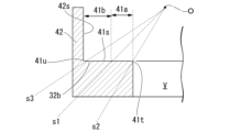
- FIG. 10 is an enlarged cross-sectional view of a main part showing a first modified example of the bearing device according to the embodiment of the present disclosure
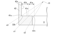
- FIG. 5 is an enlarged cross-sectional view of a main part showing a second modification of the bearing device according to the embodiment of the present disclosure
- FIG. 5 is an enlarged cross-sectional view of a main part showing a third modification of the bearing device according to the embodiment of the present disclosure
- FIG. 12 is a cross-sectional view showing a fourth modification of the bearing device according to the embodiment of the present disclosure
- a steam turbine 200 and a bearing device 100 which are examples of a rotating machine according to an embodiment of the present disclosure, will be described below with reference to FIGS.
- the steam turbine 200 includes a rotating shaft 1 , a casing 10 , a bearing device 100 (journal bearing), and a thrust bearing device 101 .
- the rotating shaft 1 extends along the axis O.
- a shaft end of the rotating shaft 1 is rotatably supported around an axis O by a pair of bearing devices 100 and only one thrust bearing device 101 .
- the bearing device 100 supports radial loads on the rotating shaft 1 .
- the thrust bearing device 101 supports a load in the axis O direction.
- a plurality of rotor blade stages 11 arranged at intervals in the direction of the axis O are provided on the outer peripheral surface of the rotating shaft 1 .
- Each rotor blade stage 11 has a plurality of rotor blades 12 extending radially outward from the outer peripheral surface of the rotating shaft 1 and arranged at intervals in the circumferential direction.
- a portion of the rotating shaft 1 where the moving blade stages 11 are provided is covered with a casing 10 from the outer peripheral side.
- the casing 10 has a tubular shape centered on the axis O.
- a plurality of stator blade stages 13 arranged at intervals in the direction of the axis O are provided on the inner peripheral surface of the casing 10 .
- Each stator vane stage 13 has a plurality of stator vanes 14 that extend radially inward from the inner peripheral surface of the casing 10 and are circumferentially spaced apart.
- the moving blade stages 11 and the stationary blade stages 13 described above are alternately arranged in the axis O direction. That is, one stator blade stage 13 is adjacent to one rotor blade stage 11 in the axis O direction.
- a steam supply pipe 15 is provided on one side of the casing 10 in the direction of the axis O.
- a steam discharge pipe 16 is provided on the other side of the casing 10 in the direction of the axis O.
- the steam supplied from the outside into the casing 10 through the steam supply pipe 15 collides alternately with the stator blade stages 13 and the moving blade stages 11 , thereby imparting rotational force to the rotating shaft 1 .
- the rotating shaft 1 rotates around the axis O.
- the rotating shaft 1 has a columnar shape extending along an axis O extending in the horizontal direction.
- the "horizontal direction” here refers to a substantially horizontal direction, and slight manufacturing errors and design tolerances are allowed.
- the bearing device 100 includes a bearing body 2, a support ring 3, and a bearing housing 4. As shown in FIG. The bearing body 2 has a ring portion 21 , a lower pad 24 , an upper pad 25 , a lower key 26 and an upper key 27 .
- the ring portion 21 covers the rotating shaft 1 from the outer peripheral side.
- the ring portion 21 has a cylindrical shape centered on the axis O. As shown in FIG.
- the lower pad 24 and the upper pad 25 have an arcuate cross-sectional shape centered on the axis O and extend in the circumferential direction.
- the inner peripheral surfaces of the lower pad 24 and the upper pad 25 are in sliding contact with the outer peripheral surface of the rotary shaft 1 via lubricating oil.
- the bearing body 2 constitutes a pad bearing having four pads.
- the support ring 3 has a support ring main body 31 and a pedestal portion 32 .
- the support ring main body 31 covers the bearing main body 2 from the outer peripheral side.
- the support ring main body 31 has a cylindrical shape centered on the axis O.
- a pair of lower keys 26 and a pair of upper keys 27 are provided on the inner peripheral surface of the support ring main body 31 .
- the lower key 26 is arranged in a region below the axis O.
- the upper key 27 is arranged in a region above the axis O.
- the lower key 26 and the upper key 27 are provided for determining the circumferential position of the bearing body 2 with respect to the support ring body 31 .
- the pair of lower keys 26 and the pair of upper keys are arranged with an interval of 90° in the circumferential direction.
- the circumferential position of the lower key 26 corresponds to the circumferential position of the lower pad 24 described above.
- the circumferential position of the upper key 27 corresponds to the circumferential position of the upper pad 25 described above.
- the circumferential dimensions of the lower key 26 and the upper key 27 are set to be equal to or slightly larger than the circumferential dimensions of the lower pad 24 and the upper pad 25 .
- the radial load of the rotating shaft 1 borne by the lower pad 24 is supported by the lower key 26 via the lower pivot 22 and the ring portion 21 .
- the pedestal portion 32 is formed integrally with the lower half portion of the support ring main body 31 .
- the pedestal portion 32 has a substantially rectangular cross-sectional shape when viewed from the axis O direction.
- the lower surface of the pedestal portion 32 is a bottom surface 32b.
- the bottom surface 32b extends in the horizontal plane.
- a surface of the base portion 32 facing the horizontal direction is a side surface 32s.
- the bottom surface 32b and the side surface 32s are orthogonal when viewed from the axis O direction.
- the bearing housing 4 is provided separately to support the support ring 3 from below.
- the bearing box 4 has a bearing box main body 41 , a pair of side wall portions 42 and a bottom portion 43 .
- the bearing housing main body 41 has a rectangular cross-sectional shape when viewed from the axis O direction.
- the upper surface of the bearing housing main body 41 is a support surface 41s.
- the support surface 41s is in contact with the bottom surface 32b of the base portion 32 described above.
- a housing space V for housing devices such as the jack 6 is provided in the central portion of the bearing housing body 41 (that is, the region immediately below the axis O and where the support surface 41s does not extend).
- a concave portion is formed as A jack 6 is used to adjust the vertical position of the support ring 3 . That is, the support surface 41s of the bearing housing main body 41 is horizontally divided into two by the accommodation space V. As shown in FIG.
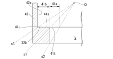
- the inner edge 41t on the inner side (axis O side) of the support surface 41s is located at a position that satisfies the following conditions.
- the extension of the straight line connecting the axis O and the center of the lower pad 24 in the circumferential direction is defined as s1.
- An extension of a straight line connecting the axis O and the inner circumferential end of the lower pad 24 is s2.
- An extension of a straight line connecting the axis O and the outer circumferential end of the lower pad 24 is s3.
- An inner edge 41t of the support surface 41s is located inside (that is, the side closer to the axis O) than the extension lines s1 and s2.
- the support surface 41s extends at least over the portions where the extension lines s1 and s2 are located. Further, the outer edge 41u of the support surface 41s is positioned outside the extension lines s1 and s3 (that is, the side away from the axis O). In other words, the support surface 41s extends at least over the portions where the extension lines s1 and s3 are located.
- the portion surrounded by the extension lines s1 and s2 is the load acting surface 41a. Furthermore, of the imaginary plane parallel to the support surface 41s, the portion surrounded by the extension lines s1 and s3 is the load acting surface 41b.
- the inner edge 41t of the support surface 41s is located inside (closer to the axis O) than the load acting surface 41a. In other words, the entire load application surface 41 a is supported by the bearing housing body 41 .
- the outer edge 41u of the support surface 41s is located outside the load acting surface 41b (on the side away from the axis O). In other words, the entire area of the load acting surface 41b is supported by the bearing housing main body 41. As shown in FIG.
- the side wall portion 42 extends upward from the outer edge 41u of the support surface 41s.
- An inner surface 42 s of the side wall portion 42 facing inward is in contact with the side surface 32 s of the base portion 32 .
- the bottom portion 43 has a plate shape that supports the bearing housing main body 41 from below.
- the support ring 3 that supports the bearing main body 2 and the bearing housing 4 are separate members. As a result, it is possible to individually produce only the support ring 3 in accordance with the dimensions of the bearing main body 2 and to share the bearing housing 4 . This makes it possible to reduce the manufacturing cost and shorten the construction period.
- the area of the above-described support surface 41s is important.
- the radial load from the rotating shaft 1 acts on the bearing housing 4 in a range surrounded by straight extension lines s1 and s3 connecting the axis O and the circumferential ends on both sides of the lower key 26. . Therefore, if no member for supporting the load is provided in these ranges, the bearing housing 4 cannot support the support ring 3 in a rigid state, and the support ring 3 may be deformed. be. As a result, it becomes difficult to stably support the rotating shaft 1 .
- this embodiment adopts the configuration described above.
- the support surface 41s of the bearing housing 4 extends on the extension line s1 of the straight line connecting the axis O and the center of the lower pad 24 in the circumferential direction.
- the entire area of the load acting surface 41 a is supported by the bearing housing body 41 .
- a radial load from the rotary shaft 1 can be directly and stably supported by the support surface 41s.
- deformation of the support ring 3 is suppressed, and smooth rotation of the rotating shaft 1 can be maintained.
- the radial load from the rotating shaft 1 is transmitted to the bearing housing 4 via the lower key 26 . Therefore, it is necessary to support the radial load in the extension range of the lower key 26 in the circumferential direction. According to the above configuration, since the support surface 41s extends on the extension lines s2 and s3 of straight lines connecting the axis O and the inner circumferential end of the lower key 26, the radial load is further stabilized. can be fully supported.
- the radial load from the rotating shaft 1 includes a horizontal component in addition to the vertically downward component.
- the side wall portion 42 of the bearing housing 4 can stably bear the component directed in the horizontal direction.
- the vertical position of the support ring 3 can be finely adjusted by the jack 6 housed in the housing space V.
- the radial load of the rotating shaft 1 can be stably supported by the bearing housing.
- the center of the upper pad 25 in the circumferential direction is located on the extension line s1 of the straight line connecting the center of the lower pad 24 in the circumferential direction and the axis O. That is, the upper pads 25 are arranged point-symmetrically with respect to the lower pads 24 with the axis O as a reference. Thereby, the reaction force of the force exerted on the lower pad 24 by the rotating shaft 1 can be stably supported by the upper pad 25 .
- the center of the upper key 27 is located on the extension line s1 of the straight line connecting the center of the lower key 26 and the axis O. That is, the upper key 27 is arranged point-symmetrically with respect to the lower key 26 with the axis O as a reference. Thereby, the reaction force of the force exerted on the lower key 26 by the rotary shaft 1 can be stably supported by the upper key 27 .
- the inner edge 41t of the support surface 41s is positioned inside (closer to the axis O) than the load acting surface 41a.
- the inner edge 41t is provided at a position overlapping the extension line s2 described above. In this case, the capacity of the housing space V can be increased while the bearing housing body 41 supports the entire load acting surface 41a.
- the inner edge 41t is provided between the extension line s1 and the extension line s2 (that is, the middle position of the load acting surface 41a). In this case, it is possible to further increase the capacity of the accommodation space V while receiving the minimum load acting on the extension lines s1 to s3. In order to maximize the volume of the accommodation space V while receiving the load, it is desirable to adopt the configuration shown as the third modified example in FIG. In this example, the inner edge 41t is positioned on the extension line s1.
- the lower pad 24 and the upper pad 25 are provided so as to contact the ring portion 21, and the lower pad 24 and the upper pad 25 are directly supported by the ring portion 21.
- the lower pivot 22 and the upper pivot 23 may be provided between the lower pad 24 and the upper pad 25 and the ring portion 21 like the bearing device 100' shown in FIG.
- the lower pivot 22 and the upper pivot 23 are arranged at central positions of the lower pad 24 and the upper pad 25 when viewed from the direction of the axis O, and support the lower pad 24 and the upper pad 25 so as to swing.
- the lower pivot 22 and the upper pivot 23 are formed so that their circumferential dimensions gradually decrease from the radially outer side toward the inner side, and the lower pad 24 and the upper pad 25 are formed at the distal ends thereof. can be rockably supported. In this case, the lower pad 24 and the upper pad 25 are indirectly supported by the ring portion 21 .
- the four-pad bearing provided with the upper pad 25 has been described as an example.
- the upper pad 25 may not necessarily be provided, and the above configuration can be applied to a bearing having only the lower pad 24 as well.
- the auxiliary equipment housed in the housing space V is not limited to a jack, and a device for treating lubricating oil may also be housed in the housing space V.
- a bearing device 100 is a bearing device 100 that supports a rotating shaft 1 that is rotatable around an axis O that extends in a horizontal direction, and includes: a bearing body 2 that supports the rotating shaft 1; a support ring main body 31 covering the bearing main body 2 from the outer peripheral side; a support ring 3 provided integrally with the support ring main body 31 and having a base portion 32 having a bottom surface 32b facing downward; and a bearing housing 4 having a support surface 41s that abuts against the bottom surface 32b.
- the support surface 41s is at least aligned with the axis O and the It extends on a straight extension line s1 connecting the center of the lower pad 24 in the circumferential direction.
- the support surface 41s extends on the extension line s1 of the straight line connecting the axis O and the center of the lower pad 24 in the circumferential direction. It can be directly and stably supported by the surface 41s.
- a bearing device 100 according to a second aspect is the bearing device 100 of (1), provided between the support ring main body 31 and the ring portion 21, and corresponding to the lower pad 24.
- the lower key 26 is arranged at a circumferential position and extends in the circumferential direction. Among them, it may extend on a straight extension line s2 connecting the inner circumferential end portion.
- the radial load from the rotating shaft 1 is transmitted to the bearing housing 4 via the lower key 26. Therefore, it is necessary to support the radial load in the extension range of the lower key 26 in the circumferential direction. According to the above configuration, since the support surface 41s extends on the extension line s2 of the straight line connecting the axis O and the inner circumferential end of the lower key 26, the radial load can be applied more stably. can support.
- a bearing device 100 according to a third aspect is the bearing device 100 of (1) or (2), wherein the bearing housing 4 includes a bearing housing main body 41 having the support surface 41s formed on the upper portion thereof. and side wall portions 42 which are provided integrally with the bearing housing main body 41 and sandwich the support ring 3 from both sides in the horizontal direction.
- the radial load from the rotating shaft 1 includes a component pointing horizontally in addition to a vertically downward component. According to the above configuration, the side wall portion 42 can stably bear the component directed in the horizontal direction.
- a bearing device 100 according to a fourth aspect is the bearing device 100 according to any one of (1) to (3), wherein the bearing housing 4 has a central portion where the support surface 41s does not extend. A concave portion serving as the accommodation space V may be formed in the portion.
- the vertical position of the support ring 3 can be precisely adjusted by arranging the jack 6 or the like in the accommodation space V, for example.
- the radial load of the rotating shaft 1 can be stably supported by the bearing box 4 according to the above configuration.
- a bearing device 100 according to a fifth aspect is the bearing device 100 according to any one of (1) to (4), wherein the bearing main body 2 is directly or It further has an upper pad 25 that is indirectly supported and is in sliding contact with the outer peripheral surface of the rotating shaft 1 .
- the upper pad 25 connects the lower pad 24 and the axis O. It may be located on the extension line s1 of the straight line.
- the upper pad 25 is positioned on the extension line s1 of the straight line connecting the lower pad 24 and the axis O. That is, the upper pads 25 are arranged point-symmetrically with respect to the lower pads 24 with the axis O as a reference. Thereby, the reaction force of the force exerted on the lower pad 24 by the rotating shaft 1 can be stably supported by the upper pad 25 and the lower pad 24 .
- a rotary machine (steam turbine 200) includes a bearing device 100 according to any one of (1) to (5), a rotating shaft 1 rotatably supported by the bearing device 100, and a casing 10 covering the rotating shaft 1 from the outside.
Landscapes
- Engineering & Computer Science (AREA)
- General Engineering & Computer Science (AREA)
- Mechanical Engineering (AREA)
- Physics & Mathematics (AREA)
- Fluid Mechanics (AREA)
- Sliding-Contact Bearings (AREA)
- Support Of The Bearing (AREA)
Abstract
Description
本願は、2021年10月29日に日本に出願された特願2021-177357号について優先権を主張し、その内容をここに援用する。
図1に示すように、蒸気タービン200は、回転軸1と、ケーシング10と、軸受装置100(ジャーナル軸受)と、スラスト軸受装置101と、を備えている。回転軸1は、軸線Oに沿って延びている。回転軸1の軸端は、一対の軸受装置100と、1つのみのスラスト軸受装置101とによって軸線O回りに回転可能に支持されている。軸受装置100は、回転軸1に対する径方向の荷重を支持する。スラスト軸受装置101は、軸線O方向の荷重を支持する。
図2に示すように、軸受装置100は、軸受本体2と、支持環3と、軸受箱4と、を備えている。軸受本体2は、リング部21と、下側パッド24と、上側パッド25と、下側キー26と、上側キー27と、を有している。
リング部21は、回転軸1を外周側から覆っている。リング部21は、軸線Oを中心とする円筒状をなしている。
支持環3は、支持環本体31と、台座部32と、を有している。支持環本体31は、軸受本体2を外周側から覆っている。支持環本体31は、軸線Oを中心とする円筒状をなしている。支持環本体31の内周面には、一対の下側キー26と一対の上側キー27が設けられている。下側キー26は、軸線Oよりも下側の領域に配置されている。上側キー27は、軸線Oよりも上側の領域に配置されている。下側キー26及び上側キー27は、支持環本体31に対して軸受本体2の周方向位置を決めるために設けられている。一対の下側キー26及び一対の上側キーは、一例として周方向に90°の間隔をあけて配置されている。
軸受箱4は、支持環3を下方から支持するために別体として設けられている。軸受箱4は、軸受箱本体41と、一対の側壁部42と、底部43と、を有している。軸受箱本体41は、軸線O方向から見て矩形状の断面形状を有している。軸受箱本体41の上側の面は、支持面41sとされている。この支持面41sは、上述した台座部32の底面32bと当接している。また、この軸受箱本体41の中央部分(つまり、軸線Oの直下の領域であって、支持面41sが延在していない領域)には、ジャッキ6等の装置を収容するための収容空間Vとしての凹部が形成されている。ジャッキ6は、支持環3の上下方向位置を調節するために用いられる。つまり、軸受箱本体41の支持面41sは、この収容空間Vによって水平方向に2つに分けられている。
従来、軸受装置100を製造するに当たっては、その適用対象となるガスタービンや蒸気タービンに合わせて、都度個別に設計されることが一般的であった。このため、軸受装置100の製造コストや工期が増大するという問題があった。そこで、本実施形態に係る軸受装置100では、軸受本体2を支持する支持環3と軸受箱4とが別体とされている。これにより、軸受本体2の寸法体格に合わせて支持環3のみを個別生産し、軸受箱4を共通化することが可能となる。これにより、製造コストや工期の短縮が可能となる。
以上、本開示の実施形態について図面を参照して詳述したが、具体的な構成はこの実施の形態に限られるものではなく、本開示の要旨を逸脱しない範囲の設計変更等も含まれる。
各実施形態に記載の軸受装置及び回転機械は、例えば以下のように把握される。
200 蒸気タービン
1 回転軸
2 軸受本体
3 支持環
4 軸受箱
6 ジャッキ
10 ケーシング
11 動翼段
12 動翼
13 静翼段
14 静翼
15 蒸気供給管
16 蒸気排出管
21 リング部
22 下側ピボット
23 上側ピボット
24 下側パッド
25 上側パッド
26 下側キー
27 上側キー
31 支持環本体
32 台座部
32b 底面
32s 側面
41 軸受箱本体
41s 支持面
41t 内側端縁
41u 外側端縁
42 側壁部
42s 内面
43 底部
101 スラスト軸受装置
O 軸線
V 収容空間
Claims (6)
- 水平方向に延びる軸線回りに回転可能な回転軸を支持する軸受装置であって、
前記回転軸を支持する軸受本体と、
前記軸受本体を外周側から覆う支持環本体、及び該支持環本体と一体に設けられるとともに下方を向く底面を有する台座部を有する支持環と、
前記支持環と別体に設けられ、前記底面に当接する支持面を有する軸受箱と、
を備え、
前記軸受本体は、
前記回転軸を外周側から覆うリング部と、
該リング部の内周面によって直接的又は間接的に支持され、前記回転軸の外周面に摺接する下側パッドと、
を有し、
前記軸線方向から見て、前記支持面は、少なくとも前記軸線と前記下側パッドの周方向における中心とを結ぶ直線の延長線上に延在している
軸受装置。 - 前記支持環本体と前記リング部との間に設けられ、前記下側パッドに対応する周方向位置に配置されるとともに周方向に延びる下側キーをさらに備え、
前記軸線方向から見て、前記支持面は、少なくとも前記軸線と前記下側キーの周方向端部のうち、内側の前記周方向端部とを結ぶ直線の延長線上に延在している
請求項1に記載の軸受装置。 - 前記軸受箱は、
上部に前記支持面が形成された軸受箱本体と、
該軸受箱本体と一体に設けられ、前記支持環を水平方向の両側から挟持する側壁部と、
を有する
請求項1又は2に記載の軸受装置。 - 前記軸受箱には、前記軸線方向から見て、前記支持面が延在していない中央部分に収容空間としての凹部が形成されている
請求項1又は2に記載の軸受装置。 - 前記軸受本体は、前記リング部の内周面によって直接的又は間接的に支持され、前記回転軸の外周面に摺接する上側パッドをさらに有し、
前記軸線方向から見て、前記上側パッドは、前記下側パッドと前記軸線とを結ぶ直線の延長線上に位置している
請求項1又は2に記載の軸受装置。 - 請求項1又は2に記載の軸受装置と、
該軸受装置によって回転可能に支持される回転軸と、
該回転軸を外側から覆うケーシングと、
を備える回転機械。
Priority Applications (5)
| Application Number | Priority Date | Filing Date | Title |
|---|---|---|---|
| US18/700,938 US12612945B2 (en) | 2021-10-29 | 2022-09-12 | Bearing device and rotating machine |
| KR1020247012581A KR20240058936A (ko) | 2021-10-29 | 2022-09-12 | 베어링 장치, 및 회전 기계 |
| DE112022005196.5T DE112022005196B4 (de) | 2021-10-29 | 2022-09-12 | Lagervorrichtung und drehmaschine |
| JP2023556178A JPWO2023074155A1 (ja) | 2021-10-29 | 2022-09-12 | |
| CN202280069768.7A CN118140058A (zh) | 2021-10-29 | 2022-09-12 | 轴承装置及旋转机械 |
Applications Claiming Priority (2)
| Application Number | Priority Date | Filing Date | Title |
|---|---|---|---|
| JP2021-177357 | 2021-10-29 | ||
| JP2021177357 | 2021-10-29 |
Publications (1)
| Publication Number | Publication Date |
|---|---|
| WO2023074155A1 true WO2023074155A1 (ja) | 2023-05-04 |
Family
ID=86157787
Family Applications (1)
| Application Number | Title | Priority Date | Filing Date |
|---|---|---|---|
| PCT/JP2022/034051 Ceased WO2023074155A1 (ja) | 2021-10-29 | 2022-09-12 | 軸受装置、及び回転機械 |
Country Status (6)
| Country | Link |
|---|---|
| US (1) | US12612945B2 (ja) |
| JP (1) | JPWO2023074155A1 (ja) |
| KR (1) | KR20240058936A (ja) |
| CN (1) | CN118140058A (ja) |
| DE (1) | DE112022005196B4 (ja) |
| WO (1) | WO2023074155A1 (ja) |
Citations (4)
| Publication number | Priority date | Publication date | Assignee | Title |
|---|---|---|---|---|
| JPH11125246A (ja) * | 1997-10-21 | 1999-05-11 | Mitsubishi Heavy Ind Ltd | 自動調心ジャーナル軸受及びそのための調心制御システム |
| JP2016142312A (ja) * | 2015-01-30 | 2016-08-08 | 三菱日立パワーシステムズ株式会社 | ジャーナル軸受装置、及び、回転機械 |
| JP2017198087A (ja) * | 2016-04-25 | 2017-11-02 | 株式会社東芝 | ジャーナル軸受を用いた流体機械 |
| JP2019108966A (ja) * | 2017-12-20 | 2019-07-04 | 三菱日立パワーシステムズ株式会社 | 軸受装置及び回転機械 |
Family Cites Families (9)
| Publication number | Priority date | Publication date | Assignee | Title |
|---|---|---|---|---|
| US1292678A (en) * | 1918-01-04 | 1919-01-28 | Dwight O Barrett | Adjustable bushing. |
| US3851935A (en) * | 1973-05-25 | 1974-12-03 | Westinghouse Electric Corp | Pivoted pad bearings |
| US5531523A (en) * | 1995-06-02 | 1996-07-02 | Westinghouse Electric Corporation | Rotor journal bearing having adjustable bearing pads |
| BRPI0511385A (pt) | 2004-06-15 | 2007-12-04 | Aly El-Shafei | métodos para controlar a instabilidade em rolamentos de pelìcula de fluido |
| JP5851880B2 (ja) | 2012-02-24 | 2016-02-03 | 三菱重工業株式会社 | 軸受装置 |
| DE102012222595A1 (de) * | 2012-12-10 | 2014-06-12 | Schaeffler Technologies Gmbh & Co. Kg | Stehlagergehäuse |
| JP6222952B2 (ja) * | 2013-03-19 | 2017-11-01 | 三菱日立パワーシステムズ株式会社 | 回転軸支持構造 |
| JP2017145813A (ja) | 2016-02-19 | 2017-08-24 | 三菱日立パワーシステムズ株式会社 | 回転機械 |
| JP7516100B2 (ja) | 2020-05-08 | 2024-07-16 | キヤノン株式会社 | 画像処理装置、画像処理装置の制御方法、及びプログラム |
-
2022
- 2022-09-12 CN CN202280069768.7A patent/CN118140058A/zh active Pending
- 2022-09-12 WO PCT/JP2022/034051 patent/WO2023074155A1/ja not_active Ceased
- 2022-09-12 DE DE112022005196.5T patent/DE112022005196B4/de active Active
- 2022-09-12 US US18/700,938 patent/US12612945B2/en active Active
- 2022-09-12 JP JP2023556178A patent/JPWO2023074155A1/ja active Pending
- 2022-09-12 KR KR1020247012581A patent/KR20240058936A/ko active Pending
Patent Citations (4)
| Publication number | Priority date | Publication date | Assignee | Title |
|---|---|---|---|---|
| JPH11125246A (ja) * | 1997-10-21 | 1999-05-11 | Mitsubishi Heavy Ind Ltd | 自動調心ジャーナル軸受及びそのための調心制御システム |
| JP2016142312A (ja) * | 2015-01-30 | 2016-08-08 | 三菱日立パワーシステムズ株式会社 | ジャーナル軸受装置、及び、回転機械 |
| JP2017198087A (ja) * | 2016-04-25 | 2017-11-02 | 株式会社東芝 | ジャーナル軸受を用いた流体機械 |
| JP2019108966A (ja) * | 2017-12-20 | 2019-07-04 | 三菱日立パワーシステムズ株式会社 | 軸受装置及び回転機械 |
Also Published As
| Publication number | Publication date |
|---|---|
| US20240410425A1 (en) | 2024-12-12 |
| US12612945B2 (en) | 2026-04-28 |
| JPWO2023074155A1 (ja) | 2023-05-04 |
| DE112022005196B4 (de) | 2025-08-21 |
| CN118140058A (zh) | 2024-06-04 |
| DE112022005196T5 (de) | 2024-09-26 |
| KR20240058936A (ko) | 2024-05-07 |
Similar Documents
| Publication | Publication Date | Title |
|---|---|---|
| CN103827508B (zh) | 轴流式流体机械及其可变静叶片驱动装置 | |
| EP2392783B1 (en) | Turbocharger with squeeze film damper bearing and centering springs | |
| CN110594285B (zh) | 气体动压轴承和高速电机 | |
| JP5414610B2 (ja) | ジャーナル軸受 | |
| US20140154072A1 (en) | Support for rolling bearings | |
| KR101443036B1 (ko) | 에어포일 쓰러스트 베어링 및 메탈메쉬포일 래디얼 베어링을 포함하는 분할형 콤보 베어링 | |
| EP2850327B1 (en) | Journal oil bearing | |
| JP5989905B2 (ja) | タービンのための可変ガイド機構、排気ガスターボチャージャーのためのタービン、及び排気ガスターボチャージャー | |
| CN218598602U (zh) | 一种止推箔片轴承 | |
| JP6725438B2 (ja) | 軸受装置及び回転機械 | |
| US20110123327A1 (en) | Bearing assembly using different type thrust bearings | |
| JP2008095703A (ja) | スラスト軸受装置 | |
| JP6469716B2 (ja) | 排気ガスターボチャージャーのための軸受装置および排気ガスターボチャージャー | |
| KR20240058936A (ko) | 베어링 장치, 및 회전 기계 | |
| CN202468703U (zh) | 上瓦瓦背安装弹簧的可倾瓦轴承 | |
| JP6650292B2 (ja) | 軸受装置、回転機械 | |
| JP2019082233A (ja) | ティルティングパッド軸受 | |
| JPS6044527B2 (ja) | 自動調心軸受 | |
| CN113090655B (zh) | 轴向气体轴承、压缩机和空调机组 | |
| CN115559992B (zh) | 一种止推箔片轴承 | |
| JP2002276304A (ja) | 流体回転機械の静翼およびその静翼を備えた流体回転機械 | |
| CN223724853U (zh) | 一种涡旋同步曲柄热膨胀自补偿结构总成 | |
| JP7774487B2 (ja) | ティルティングパッド軸受 | |
| JPS63289318A (ja) | 磁気軸受装置における保護用ラジアル玉軸受 | |
| JP7511432B2 (ja) | 軸受装置 |
Legal Events
| Date | Code | Title | Description |
|---|---|---|---|
| 121 | Ep: the epo has been informed by wipo that ep was designated in this application |
Ref document number: 22886489 Country of ref document: EP Kind code of ref document: A1 |
|
| WWE | Wipo information: entry into national phase |
Ref document number: 202417029503 Country of ref document: IN |
|
| ENP | Entry into the national phase |
Ref document number: 2023556178 Country of ref document: JP Kind code of ref document: A |
|
| ENP | Entry into the national phase |
Ref document number: 20247012581 Country of ref document: KR Kind code of ref document: A |
|
| WWE | Wipo information: entry into national phase |
Ref document number: 202280069768.7 Country of ref document: CN |
|
| 122 | Ep: pct application non-entry in european phase |
Ref document number: 22886489 Country of ref document: EP Kind code of ref document: A1 |
|
| WWG | Wipo information: grant in national office |
Ref document number: 112022005196 Country of ref document: DE |
|
| WWG | Wipo information: grant in national office |
Ref document number: 18700938 Country of ref document: US |