WO2023074071A1 - 軸ずれ判定装置、および、軸ずれ判定方法 - Google Patents
軸ずれ判定装置、および、軸ずれ判定方法 Download PDFInfo
- Publication number
- WO2023074071A1 WO2023074071A1 PCT/JP2022/029251 JP2022029251W WO2023074071A1 WO 2023074071 A1 WO2023074071 A1 WO 2023074071A1 JP 2022029251 W JP2022029251 W JP 2022029251W WO 2023074071 A1 WO2023074071 A1 WO 2023074071A1
- Authority
- WO
- WIPO (PCT)
- Prior art keywords
- vehicle
- detection
- radar
- detection point
- determination device
- Prior art date
- Legal status (The legal status is an assumption and is not a legal conclusion. Google has not performed a legal analysis and makes no representation as to the accuracy of the status listed.)
- Ceased
Links
Images


Classifications
-
- G—PHYSICS
- G08—SIGNALLING
- G08G—TRAFFIC CONTROL SYSTEMS
- G08G1/00—Traffic control systems for road vehicles
- G08G1/16—Anti-collision systems
-
- G—PHYSICS
- G01—MEASURING; TESTING
- G01S—RADIO DIRECTION-FINDING; RADIO NAVIGATION; DETERMINING DISTANCE OR VELOCITY BY USE OF RADIO WAVES; LOCATING OR PRESENCE-DETECTING BY USE OF THE REFLECTION OR RERADIATION OF RADIO WAVES; ANALOGOUS ARRANGEMENTS USING OTHER WAVES
- G01S13/00—Systems using the reflection or reradiation of radio waves, e.g. radar systems; Analogous systems using reflection or reradiation of waves whose nature or wavelength is irrelevant or unspecified
- G01S13/02—Systems using reflection of radio waves, e.g. primary radar systems; Analogous systems
- G01S13/50—Systems of measurement based on relative movement of target
- G01S13/58—Velocity or trajectory determination systems; Sense-of-movement determination systems
-
- G—PHYSICS
- G01—MEASURING; TESTING
- G01S—RADIO DIRECTION-FINDING; RADIO NAVIGATION; DETERMINING DISTANCE OR VELOCITY BY USE OF RADIO WAVES; LOCATING OR PRESENCE-DETECTING BY USE OF THE REFLECTION OR RERADIATION OF RADIO WAVES; ANALOGOUS ARRANGEMENTS USING OTHER WAVES
- G01S13/00—Systems using the reflection or reradiation of radio waves, e.g. radar systems; Analogous systems using reflection or reradiation of waves whose nature or wavelength is irrelevant or unspecified
- G01S13/88—Radar or analogous systems specially adapted for specific applications
- G01S13/93—Radar or analogous systems specially adapted for specific applications for anti-collision purposes
- G01S13/931—Radar or analogous systems specially adapted for specific applications for anti-collision purposes of land vehicles
-
- G—PHYSICS
- G01—MEASURING; TESTING
- G01S—RADIO DIRECTION-FINDING; RADIO NAVIGATION; DETERMINING DISTANCE OR VELOCITY BY USE OF RADIO WAVES; LOCATING OR PRESENCE-DETECTING BY USE OF THE REFLECTION OR RERADIATION OF RADIO WAVES; ANALOGOUS ARRANGEMENTS USING OTHER WAVES
- G01S7/00—Details of systems according to groups G01S13/00, G01S15/00, G01S17/00
- G01S7/02—Details of systems according to groups G01S13/00, G01S15/00, G01S17/00 of systems according to group G01S13/00
- G01S7/40—Means for monitoring or calibrating
- G01S7/4004—Means for monitoring or calibrating of parts of a radar system
- G01S7/4026—Antenna boresight
- G01S7/403—Antenna boresight in azimuth, i.e. in the horizontal plane
-
- G—PHYSICS
- G01—MEASURING; TESTING
- G01S—RADIO DIRECTION-FINDING; RADIO NAVIGATION; DETERMINING DISTANCE OR VELOCITY BY USE OF RADIO WAVES; LOCATING OR PRESENCE-DETECTING BY USE OF THE REFLECTION OR RERADIATION OF RADIO WAVES; ANALOGOUS ARRANGEMENTS USING OTHER WAVES
- G01S7/00—Details of systems according to groups G01S13/00, G01S15/00, G01S17/00
- G01S7/02—Details of systems according to groups G01S13/00, G01S15/00, G01S17/00 of systems according to group G01S13/00
- G01S7/40—Means for monitoring or calibrating
- G01S7/4052—Means for monitoring or calibrating by simulation of echoes
- G01S7/4082—Means for monitoring or calibrating by simulation of echoes using externally generated reference signals, e.g. via remote reflector or transponder
- G01S7/4091—Means for monitoring or calibrating by simulation of echoes using externally generated reference signals, e.g. via remote reflector or transponder during normal radar operation
-
- G—PHYSICS
- G01—MEASURING; TESTING
- G01S—RADIO DIRECTION-FINDING; RADIO NAVIGATION; DETERMINING DISTANCE OR VELOCITY BY USE OF RADIO WAVES; LOCATING OR PRESENCE-DETECTING BY USE OF THE REFLECTION OR RERADIATION OF RADIO WAVES; ANALOGOUS ARRANGEMENTS USING OTHER WAVES
- G01S13/00—Systems using the reflection or reradiation of radio waves, e.g. radar systems; Analogous systems using reflection or reradiation of waves whose nature or wavelength is irrelevant or unspecified
- G01S13/88—Radar or analogous systems specially adapted for specific applications
- G01S13/93—Radar or analogous systems specially adapted for specific applications for anti-collision purposes
- G01S13/931—Radar or analogous systems specially adapted for specific applications for anti-collision purposes of land vehicles
- G01S2013/9315—Monitoring blind spots
-
- G—PHYSICS
- G01—MEASURING; TESTING
- G01S—RADIO DIRECTION-FINDING; RADIO NAVIGATION; DETERMINING DISTANCE OR VELOCITY BY USE OF RADIO WAVES; LOCATING OR PRESENCE-DETECTING BY USE OF THE REFLECTION OR RERADIATION OF RADIO WAVES; ANALOGOUS ARRANGEMENTS USING OTHER WAVES
- G01S13/00—Systems using the reflection or reradiation of radio waves, e.g. radar systems; Analogous systems using reflection or reradiation of waves whose nature or wavelength is irrelevant or unspecified
- G01S13/88—Radar or analogous systems specially adapted for specific applications
- G01S13/93—Radar or analogous systems specially adapted for specific applications for anti-collision purposes
- G01S13/931—Radar or analogous systems specially adapted for specific applications for anti-collision purposes of land vehicles
- G01S2013/9327—Sensor installation details
- G01S2013/93274—Sensor installation details on the side of the vehicles
Definitions
- the present invention relates to an axis deviation determination device and an axis deviation determination method for determining axis deviation of a door mirror built-in radar that monitors the sides and rear of a vehicle.
- Advanced driver assistance systems are systems that call the driver's attention and assist operations according to the conditions of obstacles and moving objects around the vehicle. It is a system that automatically controls the acceleration/deceleration and steering of the own vehicle according to the situation of obstacles and moving objects.
- Each system includes sensors such as cameras, LiDAR, and radar for detecting the environment around the vehicle.
- a vehicle radar device disclosed in Patent Document 1 is known as a conventional technology for monitoring the left and right rear of a vehicle using radar.
- the abstract of the same document states that the problem is "to provide a vehicle radar device with improved detection accuracy of a radar sensor with built-in door mirrors.”
- a vehicle radar device for detecting objects around the own vehicle has a radar sensor attached to the own vehicle so that at least a part of the own vehicle body is within a detection range, and the own vehicle body detected by the radar sensor. is set as a reference position, and when an object around the vehicle is detected by the radar sensor, the direction of existence of the object is detected as a deviation angle from the reference position.” ing.
- the vehicle radar device of Patent Document 1 at least a part of the vehicle body is within the detection range of the radar sensor, and the surroundings of the vehicle are detected as described in FIGS. Under the condition that the object is also within the detection range of the radar sensor, the deviation angle from the reference position of the radar sensor can be detected.
- the present invention provides an axis deviation determination that can determine the axis deviation of the radar even when the deviation angle of the radar with built-in door mirrors becomes large and the side surface of the own vehicle does not enter the detection range of the radar. It is an object of the present invention to provide an apparatus and a method for determining shaft misalignment.
- a shaft deviation determination device of the present invention is attached to a vehicle, transmits a transmission wave to the surroundings, and based on a reflected wave reflected by an object, detects the transmission wave on the object that reflects the transmission wave.
- an object detection unit that detects a detection point; and a predetermined area in the detection range of the object detection unit is set as an own vehicle area in which the vehicle exists. and a determination unit that determines a shaft deviation of the object detection unit based on the detection result of the detection point within the vehicle area.
- the shaft deviation determination device or the shaft deviation determination method of the present invention even if the deviation angle of the radar with built-in door mirrors increases and the side of the vehicle does not enter the detection range of the radar, the radar Axial misalignment can be determined.
- FIG. 2 is a top view of the own vehicle with the radar of one embodiment deployed.
- 1 is a schematic configuration diagram of a vehicle system according to one embodiment
- FIG. FIG. 2 is a top view of the own vehicle with the radar of the embodiment stored in the rear. The top view of the own vehicle in the state where the radar of one Example was stored ahead.
- FIG. 10 is a plot diagram of detection points detected by the left radar in the deployed state while the vehicle is stopped.
- FIG. 10 is a plot diagram of detection points erroneously detected by the left radar in the front retracted state while the vehicle is stopped.
- FIG. 11 is a top view of detection points detected by the left radar in the deployed state while the vehicle is slowing down;
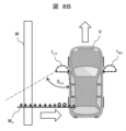
- FIG. 11 is a top view of detection points detected by the left radar in the front retracted state while the vehicle is slowing down; The top view of the detection point which the left radar of FIG. 8A erroneously detected.
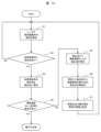
- FIG. 2 is a functional block diagram of a shaft deviation determination device of one embodiment; 4 is a processing flowchart of the shaft deviation determination device of one embodiment.
- FIG. 1 is a top view of a vehicle V with a built-in door mirror radar (hereinafter simply referred to as "radar 1") of this embodiment deployed.
- This radar 1 is a sensor that transmits a transmission wave to the surroundings and detects a detection point on an object that reflects the transmission wave based on the reflected wave reflected by the object.
- the detection range of the left radar 1L indicated by the dashed line is referred to as the left detection range SL
- the detection range of the right radar 1R indicated by the one-dot chain line is referred to as the right detection range SR .
- FIG. 2 is a schematic configuration diagram of a vehicle system for realizing the above-described ADAS and AD in own vehicle V.
- detection points which are outputs of the left radar 1L and the right radar 1R , are input to the ECU 2 (Electronic Control Unit).
- the ECU 2 detects obstacles and moving objects around the vehicle based on the detection point information (the position of each detection point and the information on the line-of-sight velocity) input from each radar, and detects the detected obstacles and the like and the vehicle. It determines the contact possibility of V.
- the vehicle control system 4 controls the vehicle control system 4 to avoid contact. is controlled to automatically brake or steer the own vehicle V.
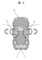
- FIG. 3 is a top view showing an example of the radar retracted state in the own vehicle V that employs the rearward retractable door mirrors.
- the left radar 1L is folded counterclockwise and the right radar 1R is folded clockwise.
- the technique disclosed in Patent Literature 1 cannot detect the axis deviation of the radar, which can detect the angle of deviation of the radar only in an environment where both the body of the vehicle and the surrounding objects of the vehicle are within the detection range.
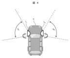
- FIG. 4 is a top view showing an example of the radar retracted state in the own vehicle V that employs the forward retracted door mirrors.
- the left radar 1L is folded clockwise and the right radar 1R is folded counterclockwise. cannot detect the axis deviation of the radar.
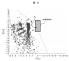
- FIG. 5 is a plot diagram specifically exemplifying the detection points detected by the left radar 1 L (see FIG. 1) in the deployed state when the own vehicle V is stopped in a certain environment.
- the front center of the vehicle V is the origin of the XY coordinate system
- the forward direction of the vehicle V is the positive direction of the X axis
- the left direction of the vehicle V is the positive direction of the Y axis.
- each detection point is arranged around the vehicle on the premise that the left radar 1L is in a deployed state . The above assumptions (deployed state) are consistent.
- the left radar 1L can arrange each detection point in the position where it should be in the left detection range SL in the deployed state, and the area where the vehicle V exists (hereinafter referred to as "vehicle area R"). (referred to as ) does not occur.
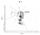
- FIG. 6 is a plot diagram specifically exemplifying detection points detected by the left radar 1 L (see FIG. 4) in the front retracted state when the own vehicle V is stopped under a different environment. .
- the left radar 1 L of this embodiment arranges each detection point around the vehicle on the assumption that the left radar 1 L is in the deployed state. front stowed state) and the above premise (deployed state) do not match.
- the left radar 1 L places each detection point in the left detection range SLV corresponding to the unfolded state instead of the position (within the left detection range S L corresponding to the front stowed state) that should be present .
- An abnormality occurs in which a detection point is arranged even in the own vehicle region R where no detection point should exist.
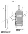
- FIG. 7 shows that the left radar 1 L (see FIG. 1) in the deployed state is positioned between the left wall W and the left side of the vehicle V under an environment where the vehicle V is slowly advancing along the left wall W.
- FIG. 4 is a top view illustrating detection points detected on a surface; In this case, there are two types of detection point groups (marked - in the figure) in the separation direction as seen from the left radar 1 L and a detection point group (marked o in the figure) where the distance is unchanged as seen from the left radar 1 L. Since there are detection points, the ECU 2, which has received the output of the left radar 1L , detects an object (wall W) on the left side of the vehicle based on the distance and direction of each detection point and the radial velocity of each detection point. A point can be distinguished from a point detected by the side of the vehicle.
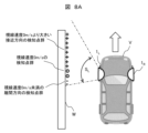
- FIG. 8A the left radar 1 L (see FIG. 4) in the front retracted state detects the left wall W under the environment where the own vehicle V is slowly advancing along the left wall W.
- FIG. 4 is a top view illustrating the original arrangement of detection points; In this case, a detection point group in the approaching direction as seen from the left radar 1 L (+ mark in the figure), a detection point group with a constant distance as seen from the left radar 1 L (o in the figure), and the left radar Since there are three types of detection points in the detection point group (-marks in the figure) in the separation direction when viewed from 1 L , assuming that the left radar 1 L is in the forward retracted state, the left radar 1 L The ECU 2, which received the output of , should be able to determine that each detection point is caused by an object (wall W) on the left side of the vehicle based on the distance and direction of each detection point and the line-of-sight velocity of each detection point.
- the left radar 1 L of this embodiment processes detection points on the premise that the left radar 1 L is in a deployed state. misunderstands that the detection point group that should be in the position shown in FIG. 8A exists in the position shown in FIG. 8B. As a result, the ECU 2, which has received the output of the left radar 1L (wrong detection point group shown in FIG. 8B), detects an object (virtual wall W V ) is falsely detected.
- the detection point cloud arranged at the wrong position when the left radar 1L is in the forward retracted state has the following characteristics. That is, first, part of the detection point group exists inside the own vehicle region R. As shown in FIG. Secondly, the detection point group within the host vehicle region R has a radial velocity (a radial velocity ⁇ 0 m/s) in the separation direction as viewed from the left radar 1L . Therefore, when a detection point group that satisfies these two conditions is detected while the own vehicle V is slowly moving forward, it is determined that a large axial misalignment of the radar 1, which cannot be detected by the technology disclosed in Patent Document 1, has occurred. On the other hand, if there is no detection point that satisfies these two conditions, it can be determined that the radar 1 has not undergone a large axial misalignment.
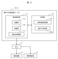
- the shaft deviation determination device 10 of the present embodiment has an object detection unit 11 and a determination unit 12, and outputs detection point groups detected by the object detection unit 11 to the ECU 2.
- the object detection unit 11 has a transmission unit 11a, a reception unit 11b, and a detection point calculation unit 11c. ing.
- the configuration other than the transmission unit 11a and the reception unit 11b is specifically hardware such as an arithmetic device such as a CPU, a storage device such as a semiconductor memory, and a communication device. is a computer with Then, each function of the above-described detection point calculation unit 11c and the like is realized by the arithmetic unit executing a predetermined program. will be described in order.
- the transmission unit 11a is a transmission antenna that transmits transmission waves around the vehicle
- the reception unit 11b is a reception antenna that receives reflected waves reflected by objects. Since the detailed configuration of these antennas, the transmission/reception control method, and the like are well known, detailed description thereof will be omitted.
- the detection point calculation unit 11c arranges detection points by objects within the detection range of the radar 1 based on the reflected waves received by the reception unit 11b, and calculates the line-of-sight velocity of each detection point as seen from the radar 1.
- various detection point groups ( ⁇ , o, and + marks in the drawings) as shown in FIGS. 7 and 8B are arranged within the detection range assuming that the radar 1 is in the deployed state.
- the own vehicle area storage unit 12a is a storage unit that stores the shape of the own vehicle area R illustrated in FIGS. 5 and 6 and the mounting positions of the left and right radars in the own vehicle area R.
- the vehicle area R stored here may be the shape of the vehicle V registered in advance, or the vehicle shape estimated from the side surface shape of the vehicle V measured by the radar 1. It may be registered after the fact.
- the shaft deviation determination unit 12b detects the above-described two conditions. It determines that a large shaft misalignment that cannot be detected by technology has occurred.
- step S1 the object detection unit 11 uses the transmission unit 11a and the reception unit 11b to receive a reflected wave from an object within the detection range of the radar 1. Arrange the detection points by the object within the detection range on the premise that there is.
- step S2 the determination unit 12 determines whether the detection point is placed within the vehicle area R stored in the vehicle area storage unit 12a. Then, if the detection point exists within the own vehicle region R, the process proceeds to step S3, and if not, the process returns to step S1.
- step S3 the determination unit 12 sets detection points within the own vehicle region R as extraction points.
- step S4 the determination unit 12 determines whether there is an extraction point with a radial velocity of less than 0 m/s, that is, whether there is a detection point in the vehicle area R in the direction away from the radar 1. Then, if there is an extraction point that satisfies the conditions, it is determined that a large shaft misalignment that cannot be detected by the technology disclosed in Patent Document 1 has occurred. In this case, the ECU 2 may use the output of the radar 1 on the premise that there is a large axial misalignment. On the other hand, if there is no extraction point that satisfies the condition, the process proceeds to step S5.
- step S4 is performed in addition to the determination of step S2 in the method of determining the axial deviation of the present invention.
- FIG. 8A and FIG. 8B are compared, it is possible to determine whether or not there is a large shaft misalignment simply by determining whether or not the detection point exists within the own vehicle region R, that is, by performing the determination in step S2. It seems to be. However, in the situation shown in FIG.
- the detected point group (marked o in the figure) whose distance is unchanged as viewed from the left radar 1 L , which is observed on the left side of the vehicle, is theoretically should be arranged along the left side of the vehicle region R, but in reality, part of the detection points may also be arranged within the vehicle region R due to the influence of measurement errors and the like.
- step S2 in addition to the determination in step S2, attention is paid to the line-of-sight velocity at the detection point in the vehicle region R.
- step S4 By performing the determination in step S4, it is possible to accurately determine whether or not there is a large shaft misalignment.
- step S5 the detection point calculation unit 11c specifies an extraction point with a radial velocity of 0 m/s (see o mark in FIG. 7) from the extraction points.
- step S6 the detection point calculation unit 11c re-extracts extraction points near the side reference position from the identified extraction points.
- step S7 the detection point calculation unit 11c sets the outermost side of the re-extracted points as the side surface of the vehicle, and registers this as the vehicle area R in the vehicle area storage unit 12a.
- step S5 the extraction point of the radial velocity within ⁇ 0.1 m/s is selected. You can choose.
- V own vehicle, 1... radar, 1 L ... left radar, SL ... left detection range, 1 R ... right radar, SR ... right detection range, 2... ECU, 3... notification device, 4... vehicle control system, DESCRIPTION OF SYMBOLS 10... Axis deviation determination apparatus 11... Object detection part 11a... Transmission part 11b... Reception part 11c... Detection point calculation part 12... Determination part 12a... Vehicle area storage part 12b... Axis deviation determination part, W... wall, W V ... virtual wall
Landscapes
- Engineering & Computer Science (AREA)
- Radar, Positioning & Navigation (AREA)
- Remote Sensing (AREA)
- Physics & Mathematics (AREA)
- General Physics & Mathematics (AREA)
- Computer Networks & Wireless Communication (AREA)
- Electromagnetism (AREA)
- Radar Systems Or Details Thereof (AREA)
Abstract
Description
まず、図5と図6を用いて、自車Vの停止中に、展開状態の左レーダ1Lが検知した検知点と、前方格納状態の左レーダ1Lが検知した検知点の相違を説明する。
次に、図7と、図8A、8Bを用いて、自車Vの徐行前進中に、展開状態の左レーダ1Lが検知した検知点と、前方格納状態の左レーダ1Lが検知した検知点の相違を説明する。
次に、図9の機能ブロック図と、図10の処理フローチャートを用いて、本実施例の軸ずれ判定装置10の詳細を説明する。なお、本実施例の軸ずれ判定装置10は、レーダ1が持つ、軸ずれ判定機能に着目した名称であり、レーダ1と軸ずれ判定装置10は、実際には同一の装置である。
以上で説明した、本実施例の軸ずれ判定装置、または、軸ずれ判定方法によれば、レーダセンサのずれ角度が大きくなり、レーダの検知範囲内に自車側面が入らなくなった場合であっても、自車領域内の検知点の視線速度に基づいて、レーダの軸ずれを判定することができる。
Claims (5)
- 車両に取り付けられ、周囲に送信波を送信するとともに物体によって反射された反射波に基づいて、前記送信波を反射する前記物体上の検知点を検知する物体検知部と、
前記物体検知部の検知範囲において所定の領域を前記車両が存在する自車領域と設定し、前記自車領域内において前記検知点を検知した場合、前記自車領域内の前記検知点の検知結果に基づいて、前記物体検知部の軸ずれを判定する判定部と、を有する軸ずれ判定装置。 - 請求項1に記載の軸ずれ判定装置であって、
前記判定部には、前記自車領域が予め記憶されていること、を特徴とする軸ずれ判定装置。 - 請求項1に記載の軸ずれ判定装置であって、
前記判定部は、前記物体検知部が検知した前記車両の側面の検知結果に応じて、前記検知範囲における前記自車領域を設定すること、を特徴とする軸ずれ判定装置。 - 請求項1に記載の軸ずれ判定装置であって、
前記物体検知部は、前記検知点の前記物体検知部に対する視線速度を求め、
前記判定部は、前記自車領域内の前記検知点の前記視線速度に基づいて、前記物体検知部の軸ずれを判定すること、を特徴とする軸ずれ判定装置。 - 車両に取り付けられた物体検知部を用い、周囲に送信波を送信するとともに物体によって反射された反射波に基づいて、前記送信波を反射する前記物体上の検知点を検知するステップと、
所定の領域を前記車両が存在する自車領域と設定し、前記自車領域内において前記検知点を検知した場合、前記自車領域内の前記検知点の検知結果に基づいて、前記物体検知部の軸ずれを判定するステップと、を有する軸ずれ判定方法。
Priority Applications (3)
| Application Number | Priority Date | Filing Date | Title |
|---|---|---|---|
| DE112022004160.9T DE112022004160T5 (de) | 2021-10-25 | 2022-07-29 | Vorrichtung zur bestimmung eines axialen versatzes und verfahren zur bestimmung eines axialen versatzes |
| US18/704,010 US20260153618A1 (en) | 2021-10-25 | 2022-07-29 | Axial offset determination device and axial offset determination method |
| JP2023556132A JP7675362B2 (ja) | 2021-10-25 | 2022-07-29 | 軸ずれ判定装置、および、軸ずれ判定方法 |
Applications Claiming Priority (2)
| Application Number | Priority Date | Filing Date | Title |
|---|---|---|---|
| JP2021173803 | 2021-10-25 | ||
| JP2021-173803 | 2021-10-25 |
Publications (1)
| Publication Number | Publication Date |
|---|---|
| WO2023074071A1 true WO2023074071A1 (ja) | 2023-05-04 |
Family
ID=86159352
Family Applications (1)
| Application Number | Title | Priority Date | Filing Date |
|---|---|---|---|
| PCT/JP2022/029251 Ceased WO2023074071A1 (ja) | 2021-10-25 | 2022-07-29 | 軸ずれ判定装置、および、軸ずれ判定方法 |
Country Status (4)
| Country | Link |
|---|---|
| US (1) | US20260153618A1 (ja) |
| JP (1) | JP7675362B2 (ja) |
| DE (1) | DE112022004160T5 (ja) |
| WO (1) | WO2023074071A1 (ja) |
Cited By (1)
| Publication number | Priority date | Publication date | Assignee | Title |
|---|---|---|---|---|
| WO2025262850A1 (ja) * | 2024-06-19 | 2025-12-26 | Astemo株式会社 | 運転支援システム、及び運転支援方法 |
Citations (3)
| Publication number | Priority date | Publication date | Assignee | Title |
|---|---|---|---|---|
| JP2003149343A (ja) * | 2001-11-14 | 2003-05-21 | Nissan Motor Co Ltd | 車載用レーダーとその検査方法および車間距離計測装置 |
| JP2013217697A (ja) * | 2012-04-05 | 2013-10-24 | Denso Corp | レーダ装置 |
| CN210617998U (zh) * | 2019-07-31 | 2020-05-26 | 杭州智波科技有限公司 | 一种用于货运和客运车辆的盲区检测设备 |
Family Cites Families (1)
| Publication number | Priority date | Publication date | Assignee | Title |
|---|---|---|---|---|
| JP2009020076A (ja) | 2007-07-13 | 2009-01-29 | Toyota Motor Corp | 車両用レーダ装置 |
-
2022
- 2022-07-29 JP JP2023556132A patent/JP7675362B2/ja active Active
- 2022-07-29 US US18/704,010 patent/US20260153618A1/en active Pending
- 2022-07-29 WO PCT/JP2022/029251 patent/WO2023074071A1/ja not_active Ceased
- 2022-07-29 DE DE112022004160.9T patent/DE112022004160T5/de active Pending
Patent Citations (3)
| Publication number | Priority date | Publication date | Assignee | Title |
|---|---|---|---|---|
| JP2003149343A (ja) * | 2001-11-14 | 2003-05-21 | Nissan Motor Co Ltd | 車載用レーダーとその検査方法および車間距離計測装置 |
| JP2013217697A (ja) * | 2012-04-05 | 2013-10-24 | Denso Corp | レーダ装置 |
| CN210617998U (zh) * | 2019-07-31 | 2020-05-26 | 杭州智波科技有限公司 | 一种用于货运和客运车辆的盲区检测设备 |
Cited By (1)
| Publication number | Priority date | Publication date | Assignee | Title |
|---|---|---|---|---|
| WO2025262850A1 (ja) * | 2024-06-19 | 2025-12-26 | Astemo株式会社 | 運転支援システム、及び運転支援方法 |
Also Published As
| Publication number | Publication date |
|---|---|
| US20260153618A1 (en) | 2026-06-04 |
| JP7675362B2 (ja) | 2025-05-14 |
| JPWO2023074071A1 (ja) | 2023-05-04 |
| DE112022004160T5 (de) | 2024-06-20 |
Similar Documents
| Publication | Publication Date | Title |
|---|---|---|
| JP6819431B2 (ja) | 注意喚起装置 | |
| JP6565893B2 (ja) | 運転支援装置 | |
| US20190073540A1 (en) | Vehicle control device, vehicle control method, and storage medium | |
| US10451722B2 (en) | In-vehicle object determining apparatus | |
| WO2016190099A1 (ja) | 車両制御装置及び車両制御方法 | |
| JP7385412B2 (ja) | 自動運転システム | |
| WO2017111135A1 (ja) | 走行支援装置及び走行支援方法 | |
| US20180170259A1 (en) | Vehicle periphery monitoring apparatus | |
| WO2018079252A1 (ja) | 物体検知装置 | |
| US11511805B2 (en) | Vehicle guidance device, method, and computer program product | |
| WO2017145845A1 (ja) | 衝突予測装置 | |
| WO2016158634A1 (ja) | 車両制御装置及び車両制御方法 | |
| WO2017170979A1 (ja) | 監視装置および監視方法 | |
| WO2016186171A1 (ja) | 物体検出装置、及び物体検出方法 | |
| WO2017164017A1 (ja) | 車両検知装置 | |
| WO2017138329A1 (ja) | 衝突予測装置 | |
| WO2019203160A1 (ja) | 運転支援システムおよび方法 | |
| JP7675362B2 (ja) | 軸ずれ判定装置、および、軸ずれ判定方法 | |
| US10843692B2 (en) | Vehicle control system | |
| WO2020008796A1 (ja) | 衝突判定装置 | |
| JP2009282929A (ja) | 車両周辺監視装置および車両周辺監視方法 | |
| JP7344077B2 (ja) | 衝突判定装置 | |
| JP4872517B2 (ja) | 障害物認識装置 | |
| US12012100B2 (en) | Driving support device, driving support method, and storage medium | |
| WO2021070881A1 (ja) | 制御装置 |
Legal Events
| Date | Code | Title | Description |
|---|---|---|---|
| 121 | Ep: the epo has been informed by wipo that ep was designated in this application |
Ref document number: 22886407 Country of ref document: EP Kind code of ref document: A1 |
|
| ENP | Entry into the national phase |
Ref document number: 2023556132 Country of ref document: JP Kind code of ref document: A |
|
| WWE | Wipo information: entry into national phase |
Ref document number: 18704010 Country of ref document: US |
|
| 122 | Ep: pct application non-entry in european phase |
Ref document number: 22886407 Country of ref document: EP Kind code of ref document: A1 |
|
| WWP | Wipo information: published in national office |
Ref document number: 18704010 Country of ref document: US |