WO2023073994A1 - 電動機駆動装置および冷凍サイクル適用機器 - Google Patents
電動機駆動装置および冷凍サイクル適用機器 Download PDFInfo
- Publication number
- WO2023073994A1 WO2023073994A1 PCT/JP2021/040278 JP2021040278W WO2023073994A1 WO 2023073994 A1 WO2023073994 A1 WO 2023073994A1 JP 2021040278 W JP2021040278 W JP 2021040278W WO 2023073994 A1 WO2023073994 A1 WO 2023073994A1
- Authority
- WO
- WIPO (PCT)
- Prior art keywords
- electric motor
- torque
- load
- command value
- value
- Prior art date
- Legal status (The legal status is an assumption and is not a legal conclusion. Google has not performed a legal analysis and makes no representation as to the accuracy of the status listed.)
- Ceased
Links
Images






Classifications
-
- H—ELECTRICITY
- H02—GENERATION; CONVERSION OR DISTRIBUTION OF ELECTRIC POWER
- H02P—CONTROL OR REGULATION OF ELECTRIC MOTORS, ELECTRIC GENERATORS OR DYNAMO-ELECTRIC CONVERTERS; CONTROLLING TRANSFORMERS, REACTORS OR CHOKE COILS
- H02P21/00—Arrangements or methods for the control of electric machines by vector control, e.g. by control of field orientation
- H02P21/14—Estimation or adaptation of machine parameters, e.g. flux, current or voltage
- H02P21/20—Estimation of torque
-
- F—MECHANICAL ENGINEERING; LIGHTING; HEATING; WEAPONS; BLASTING
- F25—REFRIGERATION OR COOLING; COMBINED HEATING AND REFRIGERATION SYSTEMS; HEAT PUMP SYSTEMS; MANUFACTURE OR STORAGE OF ICE; LIQUEFACTION SOLIDIFICATION OF GASES
- F25B—REFRIGERATION MACHINES, PLANTS OR SYSTEMS; COMBINED HEATING AND REFRIGERATION SYSTEMS; HEAT PUMP SYSTEMS
- F25B49/00—Arrangement or mounting of control or safety devices
- F25B49/02—Arrangement or mounting of control or safety devices for compression type machines, plants or systems
- F25B49/025—Motor control arrangements
-
- H—ELECTRICITY
- H02—GENERATION; CONVERSION OR DISTRIBUTION OF ELECTRIC POWER
- H02P—CONTROL OR REGULATION OF ELECTRIC MOTORS, ELECTRIC GENERATORS OR DYNAMO-ELECTRIC CONVERTERS; CONTROLLING TRANSFORMERS, REACTORS OR CHOKE COILS
- H02P21/00—Arrangements or methods for the control of electric machines by vector control, e.g. by control of field orientation
- H02P21/14—Estimation or adaptation of machine parameters, e.g. flux, current or voltage
- H02P21/18—Estimation of position or speed
-
- H—ELECTRICITY
- H02—GENERATION; CONVERSION OR DISTRIBUTION OF ELECTRIC POWER
- H02P—CONTROL OR REGULATION OF ELECTRIC MOTORS, ELECTRIC GENERATORS OR DYNAMO-ELECTRIC CONVERTERS; CONTROLLING TRANSFORMERS, REACTORS OR CHOKE COILS
- H02P21/00—Arrangements or methods for the control of electric machines by vector control, e.g. by control of field orientation
- H02P21/22—Current control, e.g. using a current control loop
-
- H—ELECTRICITY
- H02—GENERATION; CONVERSION OR DISTRIBUTION OF ELECTRIC POWER
- H02P—CONTROL OR REGULATION OF ELECTRIC MOTORS, ELECTRIC GENERATORS OR DYNAMO-ELECTRIC CONVERTERS; CONTROLLING TRANSFORMERS, REACTORS OR CHOKE COILS
- H02P23/00—Arrangements or methods for the control of AC motors characterised by a control method other than vector control
- H02P23/04—Arrangements or methods for the control of AC motors characterised by a control method other than vector control specially adapted for damping motor oscillations, e.g. for reducing hunting
-
- F—MECHANICAL ENGINEERING; LIGHTING; HEATING; WEAPONS; BLASTING
- F25—REFRIGERATION OR COOLING; COMBINED HEATING AND REFRIGERATION SYSTEMS; HEAT PUMP SYSTEMS; MANUFACTURE OR STORAGE OF ICE; LIQUEFACTION SOLIDIFICATION OF GASES
- F25B—REFRIGERATION MACHINES, PLANTS OR SYSTEMS; COMBINED HEATING AND REFRIGERATION SYSTEMS; HEAT PUMP SYSTEMS
- F25B2600/00—Control issues
- F25B2600/02—Compressor control
- F25B2600/021—Inverters therefor
-
- F—MECHANICAL ENGINEERING; LIGHTING; HEATING; WEAPONS; BLASTING
- F25—REFRIGERATION OR COOLING; COMBINED HEATING AND REFRIGERATION SYSTEMS; HEAT PUMP SYSTEMS; MANUFACTURE OR STORAGE OF ICE; LIQUEFACTION SOLIDIFICATION OF GASES
- F25B—REFRIGERATION MACHINES, PLANTS OR SYSTEMS; COMBINED HEATING AND REFRIGERATION SYSTEMS; HEAT PUMP SYSTEMS
- F25B2600/00—Control issues
- F25B2600/02—Compressor control
- F25B2600/025—Compressor control by controlling speed
- F25B2600/0253—Compressor control by controlling speed with variable speed
-
- H—ELECTRICITY
- H02—GENERATION; CONVERSION OR DISTRIBUTION OF ELECTRIC POWER
- H02P—CONTROL OR REGULATION OF ELECTRIC MOTORS, ELECTRIC GENERATORS OR DYNAMO-ELECTRIC CONVERTERS; CONTROLLING TRANSFORMERS, REACTORS OR CHOKE COILS
- H02P2207/00—Indexing scheme relating to controlling arrangements characterised by the type of motor
- H02P2207/05—Synchronous machines, e.g. with permanent magnets or DC excitation
-
- Y—GENERAL TAGGING OF NEW TECHNOLOGICAL DEVELOPMENTS; GENERAL TAGGING OF CROSS-SECTIONAL TECHNOLOGIES SPANNING OVER SEVERAL SECTIONS OF THE IPC; TECHNICAL SUBJECTS COVERED BY FORMER USPC CROSS-REFERENCE ART COLLECTIONS [XRACs] AND DIGESTS
- Y02—TECHNOLOGIES OR APPLICATIONS FOR MITIGATION OR ADAPTATION AGAINST CLIMATE CHANGE
- Y02B—CLIMATE CHANGE MITIGATION TECHNOLOGIES RELATED TO BUILDINGS, e.g. HOUSING, HOUSE APPLIANCES OR RELATED END-USER APPLICATIONS
- Y02B30/00—Energy efficient heating, ventilation or air conditioning [HVAC]
- Y02B30/70—Efficient control or regulation technologies, e.g. for control of refrigerant flow, motor or heating
Definitions
- the present disclosure relates to an electric motor drive device that drives an electric motor and a refrigeration cycle application device.
- Patent Literature 1 discloses a technique in which a motor control device performs control such that the pulsating component of the q-axis current command, that is, the AC component, becomes zero by integral control, thereby efficiently driving the motor.
- the present disclosure has been made in view of the above, and aims to obtain an electric motor drive device capable of reducing loss generated in a compressor including an electric motor and reducing power consumption in a refrigeration cycle application device including the compressor. aim.
- the electric motor drive device supplies an alternating current voltage with a variable frequency and voltage value to the electric motor whose speed changes due to periodic load fluctuations caused by the load of the compressor. and a controller for controlling the inverter.
- the control device includes a frequency estimating unit that estimates a frequency estimated value indicating the rotation state of the electric motor, a speed control unit that generates a first torque current command value based on a deviation between the frequency estimated value and the frequency command value, a load torque estimator for estimating the load torque applied to the electric motor; a compensation value calculator for calculating, based on the load torque, a torque current compensation value for accelerating operation of the electric motor in a period including a timing when the load torque is maximized; an adder that generates a second torque current command value based on the one torque current command value and the torque current compensation value.
- the electric motor drive device has the effect of reducing loss generated in a compressor including an electric motor and reducing power consumption in a refrigeration cycle application device including the compressor.
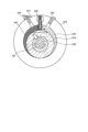
- FIG. 2 is a diagram schematically showing the loss generated in the compressor in the cross-sectional view taken along the line 2B-2B shown in FIG.
- FIG. 2 is a diagram schematically showing the process of drawing, compressing, and discharging refrigerant in the cylinder of the compressor according to the present embodiment
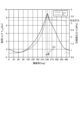
- FIG. 2 is a diagram showing the timing of the load torque in the electric motor of the compressor, the pressure in the compression chamber of the compressor, and the loss generated in the compressor according to the present embodiment
- 1 is a diagram showing a configuration example of an electric motor drive device according to the present embodiment;
- FIG. 2 is a diagram showing a configuration example of an inverter included in the electric motor drive device according to the present embodiment
- FIG. 2 is a diagram showing a configuration example of a control device included in the electric motor drive device according to the present embodiment
- FIG. 3 is a diagram showing a configuration example of a voltage command value calculation unit included in the control device according to the present embodiment
- FIG. 4 is a diagram showing an example of a disturbance observer configured by the load torque estimator of the electric motor drive device according to the present embodiment
- FIG 3 is a diagram showing an example of the load torque estimated by the load torque estimator of the electric motor drive device according to the present embodiment, the compression chamber pressure of the compressor, and the torque current compensation value generated by the compensation value calculator; A diagram showing an operation example of a control device included in the electric drive device according to the present embodiment.
- Flowchart showing the operation of the control device provided in the electric motor drive device according to the present embodiment A diagram showing an example of a hardware configuration for realizing a control device provided in the electric motor drive device according to the present embodiment.
- FIG. 1 is a diagram showing a configuration example of a refrigeration cycle equipment 900 according to the present embodiment.
- a refrigeration cycle application device 900 includes an electric motor drive device 200 .
- the refrigerating cycle applicable equipment 900 can be applied to products equipped with a refrigerating cycle, such as air conditioners, refrigerators, freezers, and heat pump water heaters.
- the electric motor drive device 200 operates the refrigeration cycle applied equipment 900 by driving the electric motor 7 built in the compressor 904 .
- a refrigeration cycle application device 900 includes a compressor 904 incorporating an electric motor 7, a four-way valve 902, an indoor heat exchanger 906, an expansion valve 908, and an outdoor heat exchanger 910, which are attached via refrigerant pipes 912. there is Inside the compressor 904 , a compression mechanism 924 that compresses refrigerant and an electric motor 7 that operates the compression mechanism 924 are provided.
- the refrigerating cycle applied equipment 900 can perform heating operation or cooling operation by switching operation of the four-way valve 902 .
- Compression mechanism 924 is driven by electric motor 7 whose speed is controlled.
- the refrigerant is pressurized by the compression mechanism 924 and sent out through the four-way valve 902, the indoor heat exchanger 906, the expansion valve 908, the outdoor heat exchanger 910, and the four-way valve 902. Return to compression mechanism 924 .
- the refrigerant is pressurized by the compression mechanism 924 and sent through the four-way valve 902, the outdoor heat exchanger 910, the expansion valve 908, the indoor heat exchanger 906, and the four-way valve 902. Return to compression mechanism 924 .
- the indoor heat exchanger 906 acts as a condenser to release heat, and the outdoor heat exchanger 910 acts as an evaporator to absorb heat.
- the outdoor heat exchanger 910 acts as a condenser to release heat, and the indoor heat exchanger 906 acts as an evaporator to absorb heat.
- the expansion valve 908 reduces the pressure of the refrigerant to expand it.
- Compressor 904 is driven by electric motor 7 whose speed is controlled.
- FIG. 2 is a cross-sectional view showing an outline of the configuration of compressor 904 provided in refrigeration cycle equipment 900 according to the present embodiment.
- FIG. 3 is a diagram schematically showing a loss generated in compressor 904 in a cross-sectional view taken along line 2B-2B shown in FIG. 2 of compressor 904 provided in refrigerating cycle equipment 900 according to the present embodiment.
- the compressor 904 is a closed rotary compressor, and includes a compressor shell 922 forming a closed container and a compression mechanism 924 arranged inside the compressor shell 922 .
- compressor 904 refrigerant is introduced from suction pipe 926 into compression mechanism 924 and discharged from discharge pipe 928 .
- Compressor shell 922 is supported by support member 930 .
- Compression mechanism 924 includes a cylinder 932 and a rotary piston 934 disposed within cylinder 932 .
- the electric motor 7 is arranged within the compressor shell 922 and includes a rotor 7a and a stator 7b that rotatably holds the rotor 7a.
- Rotor 7 a is coupled to shaft 936 .
- the shaft 936 is rotatably held with respect to a frame (not shown) by bearings (not shown).
- the frame is fixed to compressor shell 922 .
- Shaft 936 is coupled to rotary piston 934 . Rotation of the rotor 7 a of the electric motor 7 is transmitted to the rotary piston 934 via the shaft 936 .
- the speed of the electric motor 7 changes due to periodic load fluctuations caused by the load of the compressor 904 .
- a suction port 942 and a discharge port 944 are formed in the cylinder 932 .
- a vane 946 is provided within the cylinder 932 .
- the suction port 942 is connected to the suction pipe 926 .
- the discharge port 944 is connected to the discharge pipe 928 .
- the suction port 942 and the discharge port 944 are conceptually illustrated, and their respective positions do not necessarily represent their actual positions accurately.
- the vanes 946 are biased toward the center of the cylinder 932 so that they can move in the radial direction of the cylinder 932 while sliding on the peripheral surface of the rotary piston 934 .
- rotary piston 934 rotates in the direction indicated by arrow RP.
- vaporized refrigerant is sucked from the suction port 942 , the refrigerant is compressed, and the refrigerant liquefied by the compression is discharged from the discharge port 944 .
- a discharge overshoot loss which is a mechanical loss, occurs at the timing when the discharge valve 947 opens.
- the pressure applied to rotary piston 934 changes during a series of suction, compression, and discharge steps. This change in pressure results in a change in the load torque T load applied to the electric motor 7 of the compressor 904 .
- FIG. 4 is a diagram schematically showing the process of drawing, compressing, and discharging refrigerant in cylinder 932 of compressor 904 according to the present embodiment.
- FIG. 5 is a diagram showing timings of load torque T load in electric motor 7 of compressor 904, compression chamber pressure P c of compressor 904, and loss generated in compressor 904 according to the present embodiment.
- the mechanical angles shown in FIG. 4 correspond to the mechanical angles of the horizontal axis shown in FIG.
- the horizontal axis indicates the mechanical angle of one cycle of the electric motor 7
- the vertical axis indicates the load torque standard waveform, that is, the load torque T load in the electric motor 7 and the compression chamber pressure P c of the compressor 904 .
- FIG. 5 the horizontal axis indicates the mechanical angle of one cycle of the electric motor 7
- the vertical axis indicates the load torque standard waveform, that is, the load torque T load in the electric motor 7 and the compression chamber pressure P c of the compressor 904 .
- the refrigerant is sucked into the suction chamber 935 of the cylinder 932 .
- the rotary piston 934 rotates in the order of FIG. 4(a), FIG. 4(b), FIG. 4(c), and FIG. be.
- the refrigerant is newly sucked into the suction chamber 935 and the refrigerant filled in the portion indicated by the excluded volume is compressed in the compression chamber 945 .
- the rotary piston 934 rotates in the order shown in FIGS. 4(b) and 4(c), and the discharge valve 947 opens to discharge the compressed refrigerant.
- the period of FIG. 4(c) is the period of (A) shown in FIG. 5, which is the timing at which the ejection overshoot loss occurs.
- electric motor drive device 200 drives electric motor 7 and controls electric motor 7 to reduce discharge overshoot loss that occurs in compressor 904 .
- FIG. 6 is a diagram showing a configuration example of the electric motor drive device 200 according to this embodiment.
- FIG. 7 is a diagram showing a configuration example of inverter 30 included in electric motor drive device 200 according to the present embodiment.
- Electric motor drive device 200 is connected to AC power supply 1 and electric motor 7 .
- the electric motor drive device 200 rectifies the AC voltage supplied from the AC power supply 1 , converts it to AC voltage again, supplies the AC voltage to the electric motor 7 , and drives the electric motor 7 .
- Electric motor drive device 200 includes reactor 2 , rectifier circuit 3 , smoothing capacitor 5 , inverter 30 , bus voltage detector 10 , bus current detector 40 , and controller 100 .
- the rectifier circuit 3 includes four diodes D1, D2, D3 and D4.
- the four diodes D1-D4 are bridge-connected to form a diode bridge circuit.
- the rectifier circuit 3 rectifies the AC voltage supplied from the AC power supply 1 by a diode bridge circuit composed of four diodes D1 to D4.
- one end of the input terminal is connected to the AC power supply 1 through the reactor 2 , and the other end of the input terminal is connected to the AC power supply 1 .
- an output terminal is connected to a smoothing capacitor 5 .
- a smoothing capacitor 5 smoothes the output voltage of the rectifier circuit 3 .
- One electrode of the smoothing capacitor 5 is connected to the first output terminal of the rectifier circuit 3 and the high potential side, ie, the positive side DC bus 12a.
- the other electrode of the smoothing capacitor 5 is connected to the second output terminal of the rectifier circuit 3 and the low potential side, that is, the negative DC bus 12b.
- the voltage smoothed by the smoothing capacitor 5 is called a bus voltage Vdc .
- DC buses 12 a and 12 b are lines that connect output terminals of rectifier circuit 3 , electrodes of smoothing capacitor 5 , and input terminals of inverter main circuit 310 .
- Inverter 30 receives the voltage across smoothing capacitor 5, that is, bus voltage Vdc , generates a three-phase AC voltage with a variable frequency and voltage value, and supplies it to electric motor 7 via output lines 331-333.
- the inverter 30 includes an inverter main circuit 310 and a drive circuit 350, as shown in FIG. Input terminals of the inverter main circuit 310 are connected to the DC buses 12a and 12b.
- the inverter main circuit 310 includes switching elements 311-316. Freewheeling rectifying elements 321 to 326 are connected in anti-parallel to the switching elements 311 to 316, respectively.
- the drive circuit 350 generates drive signals Sr1-Sr6 based on PWM (Pulse Width Modulation) signals Sm1-Sm6 output from the control device 100.
- PWM Pulse Width Modulation
- the drive circuit 350 controls on/off of the switching elements 311-316 by the drive signals Sr1-Sr6.
- the inverter 30 can supply the three-phase AC voltage with variable frequency and variable voltage to the electric motor 7 via the output lines 331 to 333 .
- the PWM signals Sm1 to Sm6 are signals having a logic circuit signal level, that is, a magnitude of 0V to 5V.
- the PWM signals Sm1 to Sm6 are signals having the ground potential of the control device 100 as a reference potential.
- the driving signals Sr1 to Sr6 are signals having voltage levels necessary to control the switching elements 311 to 316, eg, -15V to +15V.
- the drive signals Sr1 to Sr6 are signals having the potential of the negative terminal, that is, the emitter terminal of the corresponding switching element as a reference potential.
- the electric motor 7 is, for example, a three-phase permanent magnet synchronous motor. In this embodiment, it is assumed that the electric motor 7 drives a load element whose load torque T load periodically fluctuates, specifically the compressor 904 . In the following description, the electric motor 7 may be called a motor.
- Bus voltage detector 10 detects the voltage between DC buses 12a and 12b as bus voltage Vdc .
- the bus voltage detection unit 10 includes, for example, a voltage dividing circuit that divides voltage with series-connected resistors.
- the bus voltage detection unit 10 converts the detected bus voltage V dc into a voltage suitable for processing in the control device 100 using a voltage dividing circuit, for example, a voltage of 5 V or less, and converts it into a voltage detection signal that is an analog signal. Output to the control device 100 .
- the voltage detection signal output from the bus voltage detection unit 10 to the control device 100 is converted from an analog signal to a digital signal by an AD (Analog to Digital) conversion unit (not shown) in the control device 100, and internal processing in the control device 100 used for
- AD Analog to Digital
- the bus current detector 40 includes a shunt resistor inserted in the DC bus 12b.
- Bus current detection unit 40 detects the current input to inverter 30 as DC current Idc using a shunt resistor.
- the bus current detector 40 outputs the detected DC current Idc to the controller 100 as a current detection signal, which is an analog signal.
- a current detection signal output from the bus current detector 40 to the controller 100 is converted from an analog signal to a digital signal by an AD converter (not shown) in the controller 100 and used for internal processing in the controller 100 .
- the control device 100 generates PWM signals Sm1 to Sm6 to control the inverter 30.
- Control device 100 outputs PWM signals Sm1 to Sm6 to inverter 30 to control inverter 30 .
- control device 100 controls inverter 30 to change the angular frequency ⁇ and the voltage value of the output voltage of inverter 30 .
- the angular frequency ⁇ of the output voltage of the inverter 30 is represented by the same symbol ⁇ as the angular frequency of the output voltage, and determines the rotational angular velocity of the electric motor 7 in electrical angle.
- the rotational angular velocity may be simply referred to as rotational speed
- the angular frequency may simply be referred to as frequency.
- the control device 100 generates an excitation current command value i ⁇ * based on the phase currents i u , iv , and i w flowing through the electric motor 7 , and generates a ⁇ -axis voltage command value V ⁇ based on the excitation current command value i ⁇ * . * is generated. Further, the control device 100 calculates the first torque current command value i ⁇ * such that the estimated frequency value ⁇ est of the electric motor 7 matches the frequency command value ⁇ e * , and the first torque current command value i ⁇ A second torque current command value i ⁇ ** corrected for * is calculated, and a ⁇ -axis voltage command value V ⁇ * is generated based on the second torque current command value i ⁇ ** .
- Control device 100 controls inverter 30 based on ⁇ -axis voltage command value V ⁇ * and ⁇ -axis voltage command value V ⁇ * .
- control device 100 performs control in a rotating coordinate system having ⁇ -axes and ⁇ -axes.
- FIG. 8 is a diagram showing a configuration example of the control device 100 included in the electric motor drive device 200 according to the present embodiment.
- the control device 100 includes an operation control section 102 and an inverter control section 110 .
- the operation control unit 102 receives command information Q e from the outside and generates a frequency command value ⁇ e * based on the command information Q e .
- the control device 100 controls the operation of each part of the air conditioner based on the command information Qe .
- the command information Qe includes, for example, a temperature detected by a temperature sensor (not shown), information indicating a set temperature instructed by a remote controller (not shown), operation mode selection information, operation start and operation end instruction information, and the like. is.
- the operation modes are, for example, heating, cooling, and dehumidification.
- the operation control unit 102 may be outside the control device 100 . That is, control device 100 may be configured to acquire frequency command value ⁇ e * from the outside.
- Inverter control unit 110 includes current restoration unit 111, three-phase two-phase conversion unit 112, voltage command value calculation unit 115, two-phase three-phase conversion unit 116, PWM signal generation unit 117, and electric phase calculation unit 118. and an excitation current command value generator 119 .
- a current restoration unit 111 restores the phase currents i u , iv , and i w flowing through the electric motor 7 based on the DC current I dc detected by the bus current detection unit 40 .
- Current restoration unit 111 samples DC current Idc detected by bus current detection unit 40 at timing determined based on PWM signals Sm1 to Sm6 generated by PWM signal generation unit 117, thereby obtaining phase current i u , i v , i w can be recovered.
- the three-phase to two-phase conversion unit 112 converts the phase currents i u , iv , and i w restored by the current restoration unit 111 to the ⁇ -axis using the electric phase ⁇ e generated by the electric phase calculation unit 118 described later.
- An excitation current i ⁇ that is a current and a torque current i ⁇ that is a ⁇ -axis current, that is, are converted into current values of the ⁇ - ⁇ axis.
- the excitation current command value generation unit 119 generates the excitation current command value i ⁇ * in the above-described rotating coordinate system. Specifically, the excitation current command value generation unit 119 obtains the optimum excitation current command value i ⁇ * for driving the electric motor 7 with the highest efficiency based on the torque current i ⁇ . Based on the torque current i ⁇ , the excitation current command value generation unit 119 generates the current phase ⁇ m and An exciting current command value i ⁇ * is output.
- the excitation current command value generator 119 obtains the excitation current command value i ⁇ * based on the torque current i ⁇ , but this is an example and the present invention is not limited to this. Even if the excitation current command value generator 119 obtains the excitation current command value i ⁇ * based on the excitation current i ⁇ , the frequency command value ⁇ e * , etc., the same effect can be obtained.
- the voltage command value calculation unit 115 uses the frequency command value ⁇ e * obtained from the operation control unit 102, the excitation current i ⁇ and the torque current i ⁇ obtained from the three-phase two-phase conversion unit 112, and the excitation current command value generation unit Based on the excitation current command value i ⁇ * obtained from 119, the ⁇ -axis voltage command value V ⁇ * and the ⁇ -axis voltage command value V ⁇ * are generated. Furthermore, the voltage command value calculation unit 115 calculates the frequency estimated value ⁇ est based on the ⁇ -axis voltage command value V ⁇ * , the ⁇ -axis voltage command value V ⁇ * , the excitation current i ⁇ , and the torque current i ⁇ . to estimate A detailed operation of voltage command value calculation unit 115 will be described later.
- the electric phase calculator 118 calculates the electric phase ⁇ e by integrating the estimated frequency value ⁇ est acquired from the voltage command value calculator 115 .
- Two-to-three phase converter 116 converts ⁇ -axis voltage command value V ⁇ * and ⁇ -axis voltage command value V ⁇ * obtained from voltage command value calculator 115, that is, voltage command values in a two-phase coordinate system, to electrical phase calculation.
- the electric phase ⁇ e acquired from the unit 118 the three-phase voltage command values Vu * , Vv * , Vw * , which are the output voltage command values in the three-phase coordinate system, are converted.
- PWM signal generation unit 117 converts three-phase voltage command values V u * , V v * , V w * acquired from two-to-three phase conversion unit 116 and bus voltage V dc detected by bus voltage detection unit 10 to The comparison generates PWM signals Sm1-Sm6.
- the PWM signal generator 117 can also stop the electric motor 7 by not outputting the PWM signals Sm1 to Sm6.
- FIG. 9 is a diagram showing a configuration example of voltage command value calculation section 115 included in control device 100 according to the present embodiment.
- Voltage command value calculation unit 115 includes frequency estimation unit 501, speed control unit 502, load torque estimation unit 503, compensation value calculation unit 504, addition unit 505, subtraction units 506 and 507, and excitation current control unit. 508 and a torque current control unit 509 .
- a frequency estimator 501 estimates a frequency estimation value ⁇ est that indicates the rotation state of the electric motor 7 . Specifically, the frequency estimator 501 supplies the electric motor 7 with the excitation current i ⁇ , the torque current i ⁇ , the ⁇ -axis voltage command value V ⁇ * , and the ⁇ -axis voltage command value V ⁇ * . Estimate the frequency of the applied voltage and output it as the frequency estimate ⁇ est .
- the speed control unit 502 generates a first torque current command value i ⁇ * based on the frequency command value ⁇ e * obtained from the operation control unit 102 and the frequency estimated value ⁇ est obtained from the frequency estimating unit 501 . do.
- the speed control unit 502 uses a controller such as a proportional integral (PI) controller based on the difference between the frequency command value ⁇ e * and the frequency estimated value ⁇ est to obtain the frequency estimated value ⁇ est generates a first torque current command value i ⁇ * that matches the frequency command value ⁇ e * .
- PI proportional integral
- the load torque estimator 503 estimates the load torque T load applied to the electric motor 7 based on the excitation current i ⁇ , the torque current i ⁇ , and the estimated frequency ⁇ est obtained from the frequency estimator 501 .
- a compensation value calculation unit 504 calculates a torque current compensation value i ⁇ _trq * that reduces the discharge overshoot loss generated in the electric motor 7 with respect to the load torque T load estimated by the load torque estimation unit 503 .
- a detailed method of generating torque current compensation value i ⁇ _trq * in compensation value calculation section 504 will be described later.
- Addition unit 505 adds torque current compensation value i ⁇ _trq * to first torque current command value i ⁇ * .
- Addition unit 505 outputs (i ⁇ * +i ⁇ _trq * ) obtained by adding torque current compensation value i ⁇ _trq * to first torque current command value i ⁇ * as second torque current command value i ⁇ ** .
- the subtraction unit 506 calculates the difference (i ⁇ * ⁇ i ⁇ ) of the excitation current i ⁇ with respect to the excitation current command value i ⁇ * .
- the subtraction unit 507 calculates the difference (i ⁇ ** - i ⁇ ) of the torque current i ⁇ with respect to the second torque current command value i ⁇ **.
- An excitation current control unit 508 performs a proportional integral operation on the difference (i ⁇ * ⁇ i ⁇ ) calculated by the subtraction unit 506 to bring the difference (i ⁇ * ⁇ i ⁇ ) close to zero. Generate the value V ⁇ * .
- the excitation current control unit 508 generates the ⁇ -axis voltage command value V ⁇ * in this manner, thereby performing control for matching the excitation current i ⁇ with the excitation current command value i ⁇ * .
- a torque current control unit 509 performs a proportional integral operation on the difference (i ⁇ ** - i ⁇ ) calculated by the subtraction unit 507 to bring the difference (i ⁇ ** - i ⁇ ) close to zero.
- a voltage command value V ⁇ * is generated.
- the torque current control unit 509 performs control to match the torque current i ⁇ with the second torque current command value i ⁇ ** .
- the proportional gain Kp_ ⁇ of the excitation current control unit 508 is expressed by ⁇ cc ⁇ L ⁇
- the integral gain Ki_ ⁇ is expressed using the phase resistance R of the electric motor 7 ( R/L ⁇ ) ⁇ Kp_ ⁇ .
- the proportional gain Kp_ ⁇ of the torque current control unit 509 is expressed by ⁇ cc ⁇ L ⁇
- the integral gain Ki_ ⁇ is expressed by (R/L ⁇ ) ⁇ Kp_ ⁇ using the phase resistance R of the electric motor 7 .
- the voltage command value calculation unit 115 can shorten the time for the exciting current i ⁇ to follow the exciting current command value i ⁇ * .
- the time for the torque current i ⁇ to follow the value i ⁇ * can be shortened.
- the current control response ⁇ cc cannot be infinitely increased, and must be set to a value that is relatively small with respect to the control cycle.
- motor drive device 200 is configured to restore phase currents i u , iv , and i w from DC current I dc on the input side of inverter 30 , but is not limited to this.
- Electric motor drive device 200 may include current detectors in output lines 331, 332, and 333 of inverter 30 to detect phase currents iu , iv , and iw . In this case, the electric motor drive device 200 may use the current value detected by the current detector instead of the current restored by the current restoration section 111 .
- the switching elements 311 to 316 of the inverter main circuit 310 are assumed to be IGBTs (Insulated Gate Bipolar Transistors), MOSFETs (Metal Oxide Semiconductor Field Effect Transistors), etc., but switching can be performed. Any element may be used as long as it is a suitable element.
- the switching elements 311 to 316 are MOSFETs
- the MOSFETs have parasitic diodes due to their structure, so the same effect can be obtained without connecting the rectifying elements 321 to 326 for freewheeling in anti-parallel. can be done.
- the materials constituting the switching elements 311 to 316 not only silicon (Si) but also wide bandgap semiconductors such as silicon carbide (SiC), gallium nitride (GaN), and diamond are used. Loss can be reduced.
- the electric motor driving device 200 controls to accelerate the electric motor 7 at the timing when the discharge overshoot loss occurs.
- the electric motor drive device 200 can operate the compressor 904 with high efficiency while reducing the discharge overshoot loss of the compressor 904 .
- a specific control method in electric motor drive device 200 will be described. is not limited to
- the load torque estimator 503 uses a disturbance observer to estimate the load torque T load .
- the load torque T load can be derived as the following equation (1) from the equation of motion using the output torque T m , the rotational angular velocity ⁇ m , and the inertia J m of the load.
- the equation (1) can be expressed as an arithmetic expression of the disturbance observer like the equation (2).
- the estimated value of the load torque T load is T load ⁇
- the Laplace operator is s.
- FIG. 10 is a diagram showing an example of a disturbance observer configured by load torque estimation section 503 of electric motor drive device 200 according to the present embodiment.
- the load torque estimator 503 can obtain the load torque estimated value T load ⁇ , which is the estimated value of the load torque T load .
- the output torque Tm is represented by the formula (4).
- Pm is the number of pole pairs of the motor 7
- ⁇ f is the magnetic flux of the motor 7
- Ld is the d-axis inductance
- Lq is the q-axis inductance.
- the load torque estimator 503 can calculate the output torque Tm , for example, by storing these parameters in advance.
- Load torque estimator 503 outputs load torque estimated value T load ⁇ to compensation value calculator 504 as estimated load torque T load .
- FIG. 11 shows load torque T load estimated by load torque estimating section 503 of electric motor drive device 200 according to the present embodiment, compression chamber pressure P c of compressor 904, and torque current generated by compensation value computing section 504.
- FIG. 4 is a diagram showing an example of compensation value i ⁇ _trq * ;
- compensation value calculator 504 calculates torque current compensation value i ⁇ _trq Generate and output.
- the adding section 505 adds the torque current compensation value i ⁇ _trq * to the first torque current command value i ⁇ * to generate the second torque current command value i ⁇ ** .
- the control device 100 adds the torque current compensation value i ⁇ _trq * during the period (A) including the timing at which the load torque T load peaks and the discharge valve 947 opens, thereby causing rapid acceleration.
- the electric motor 7, that is, the compressor 904 is driven as follows.
- the limit value of the torque current compensation value i ⁇ _trq * generated by the compensation value calculation unit 504 is represented by Equation (5). That is, the limit value i ⁇ _trq * _lim of the torque current compensation value i ⁇ _trq * is a value obtained by subtracting the first torque current command value i ⁇ * from the overall limit value i ⁇ _lim * of the torque current i ⁇ .
- the torque current compensation value i ⁇ _trq * may be just above the limit as shown in FIG. 11(a), or may have some margin as shown in FIG. 11(b). Also, there is no particular limitation on the slope of increasing the torque current compensation value i ⁇ _trq * . As a result, the control device 100 can shorten the time during which the discharge overshoot loss occurs, and can reduce the discharge overshoot loss.
- the speed is equal to the speed command value on average outside the period of (A) in FIG. There is no problem even if the first torque current command value i ⁇ * is adjusted so as to follow.
- the control device 100 should set the timing of switching the torque current compensation value i ⁇ _trq * in the period (A) shown in FIG. is not limited to the timing shown in .
- the electric motor drive device 200 is used in the refrigeration cycle application equipment 900 including the compressor 904, and depending on the type of refrigerant compressed by the compressor 904, the value of the torque current compensation value i ⁇ _trq * , the torque current compensation value i Since the mechanical loss changes depending on the period during which the value of ⁇ _trq * is increased or decreased, the optimum torque current compensation value i ⁇ _trq * differs under each condition.
- FIG. 12 is a diagram showing an operation example of control device 100 included in electric motor drive device 200 according to the present embodiment.
- FIG. 12(a) shows the rotation speed of the electric motor 7 when the rotation speed of the electric motor 7 is changed as in the present embodiment and when the rotation speed of the electric motor 7 is not changed as a comparative example. Further, FIG. 12(a) shows a component obtained by differentiating the rotation speed when the rotation speed of the electric motor 7 is changed as in the present embodiment.
- FIG. 12(b) shows the discharge overshoot loss when the rotation speed of the electric motor 7 is changed as in this embodiment and when the rotation speed of the electric motor 7 is not changed as a comparative example.
- the horizontal axes both indicate time.
- the control device 100 adds the torque current compensation values i ⁇ _trq * in the period of (A) of FIGS. An effect of suppressing loss can be obtained.
- the refrigerant used in the refrigeration cycle applied device 900 according to the present embodiment is not particularly limited, and may be a so-called old refrigerant or a new refrigerant.
- Old refrigerants are, for example, refrigerants such as R410 and R32.
- the new refrigerants are, for example, refrigerants such as trifluoroethylene (HFO1123), trifluoromethane (CF31), propane (R290).
- FIG. 13 is a flowchart showing the operation of control device 100 included in electric motor drive device 200 according to the present embodiment.
- the flowchart shown in FIG. 13 specifically shows the operation of the voltage command value calculation unit 115 .
- the frequency estimator 501 estimates a frequency estimation value ⁇ est which is the current speed of the electric motor 7 and indicates the rotation state (step S1).
- the speed control unit 502 generates the first torque current command value i ⁇ * based on the deviation between the frequency estimated value ⁇ est of the electric motor 7 and the frequency command value ⁇ e * (step S2).
- the load torque estimator 503 estimates the load torque T load applied to the electric motor 7 (step S3).
- the compensation value calculation unit 504 calculates a torque current compensation value i ⁇ _trq * that accelerates the electric motor 7 one or more times during one cycle of the mechanical angle of the electric motor 7 (step S4).
- the adder 505 generates a second torque current command value i ⁇ ** based on the first torque current command value i ⁇ * and the torque current compensation value i ⁇ _trq * (step S5).
- the subtractor 506 calculates the difference (i ⁇ * ⁇ i ⁇ ) between the excitation current command value i ⁇ * and the excitation current i ⁇ (step S6).
- the subtraction unit 507 calculates the difference (i ⁇ ** - i ⁇ ) between the second torque current command value i ⁇ ** and the torque current i ⁇ (step S7).
- the excitation current control unit 508 generates the ⁇ -axis voltage command value V ⁇ * based on the difference (i ⁇ * ⁇ i ⁇ ) calculated by the subtraction unit 506 (step S8).
- Torque current control unit 509 generates ⁇ -axis voltage command value V ⁇ * based on the difference (i ⁇ ** - i ⁇ ) calculated by subtraction unit 507 (step S9).
- the compensation value calculation unit 504 calculates a torque current compensation value i ⁇ _trq * for accelerating the electric motor 7 in a period including the timing when the load torque T load reaches a maximum so as to reduce the discharge overshoot loss of the compressor 904. Calculate.
- the period including the timing at which the load torque T load becomes maximum is the period (A) shown in FIG.
- the compensation value calculation unit 504 calculates the torque current compensation value i ⁇ _trq * so as to accelerate the electric motor 7 when the load torque T load exceeds the threshold. At this time, the compensation value calculation unit 504 calculates the threshold value based on the load torque T load estimated in the previous control. Compensation value calculation section 504 may use the latest load torque T load as the load torque T load estimated in the previous control , or use the average value of the load torque T load for a plurality of times including the latest. good too.
- the compensation value calculation unit 504 may accelerate the electric motor 7 based on the mechanical angle corresponding to the estimated load torque T load to calculate the torque current compensation value i ⁇ _trq * . Further, the compensation value calculation unit 504 calculates the torque current compensation value i ⁇ _trq * so as to accelerate the electric motor 7 based on the above threshold and the mechanical angle corresponding to the estimated load torque T load . good too. Further, the compensation value calculation unit 504 may keep the magnitude of the acceleration constant during the period in which the electric motor 7 is accelerated, or may change the magnitude of the acceleration according to the estimated load torque T load or the like. good.
- FIG. 14 is a diagram showing an example of a hardware configuration for realizing control device 100 provided in electric motor drive device 200 according to the present embodiment.
- Control device 100 is implemented by processor 91 and memory 92 .
- the processor 91 is a CPU (Central Processing Unit, central processing unit, processing unit, arithmetic unit, microprocessor, microcomputer, processor, DSP (Digital Signal Processor)), or a system LSI (Large Scale Integration).
- the memory 92 includes RAM (Random Access Memory), ROM (Read Only Memory), flash memory, EPROM (Erasable Programmable Read Only Memory), EEPROM (registered trademark) (Electrically Erasable Programmable Read Non-volatile or volatile such as Only Memory)
- RAM Random Access Memory
- ROM Read Only Memory
- flash memory flash memory
- EPROM Erasable Programmable Read Only Memory
- EEPROM registered trademark
- a semiconductor memory can be exemplified.
- the memory 92 is not limited to these, and may be a magnetic disk, an optical disk, a compact disk, a mini disk, or a DVD (Digital Versatile Disc).
- the control device 100 estimates the load torque T load of the electric motor 7, and the load torque T load is A torque current command value is controlled so as to accelerate in a period including the largest mechanical angle, and discharge overshoot loss is reduced.
- the electric motor drive device 200 can reduce loss generated in the compressor 904 including the electric motor 7 and reduce power consumption in the refrigeration cycle application equipment 900 including the compressor 904 .
- the electric motor drive device 200 reduces the mechanical loss due to the overshoot loss that occurs at the timing when the discharge valve 947 opens, thereby increasing the efficiency of the refrigerating cycle device 900. driving can be realized.
- Electric motor drive device 200 can apply the above-described control according to the present embodiment even when compressor 904 used in refrigeration cycle applied equipment 900 is a twin rotary compressor, a scroll compressor, or the like.
- the compensation value calculation unit 504 calculates the torque current compensation value i ⁇ _trq * that accompanies the acceleration operation of the electric motor 7 according to the number of load fluctuations that occur during one rotation of the electric motor 7 .
- the motor drive device 200 can be applied to any control system that has a speed controller and a current controller in control means for driving the motor 7 .
- the electric motor drive device 200 of the present embodiment is suitable for the refrigeration cycle application equipment 900 that switches the windings of the electric motor 7 for use.
- an air conditioner is given as an example of the refrigeration cycle application equipment 900, the present embodiment is not limited to this, and can be applied to refrigerators, freezers, heat pump water heaters, and the like, for example.
Landscapes
- Engineering & Computer Science (AREA)
- Power Engineering (AREA)
- Physics & Mathematics (AREA)
- Mechanical Engineering (AREA)
- Thermal Sciences (AREA)
- General Engineering & Computer Science (AREA)
- Control Of Ac Motors In General (AREA)
Priority Applications (4)
| Application Number | Priority Date | Filing Date | Title |
|---|---|---|---|
| US18/689,621 US20250015740A1 (en) | 2021-11-01 | 2021-11-01 | Motor driving device and refrigeration cycle-incorporating device |
| CN202180103691.6A CN118160212A (zh) | 2021-11-01 | 2021-11-01 | 电动机驱动装置和制冷循环应用设备 |
| JP2023556096A JPWO2023073994A1 (https=) | 2021-11-01 | 2021-11-01 | |
| PCT/JP2021/040278 WO2023073994A1 (ja) | 2021-11-01 | 2021-11-01 | 電動機駆動装置および冷凍サイクル適用機器 |
Applications Claiming Priority (1)
| Application Number | Priority Date | Filing Date | Title |
|---|---|---|---|
| PCT/JP2021/040278 WO2023073994A1 (ja) | 2021-11-01 | 2021-11-01 | 電動機駆動装置および冷凍サイクル適用機器 |
Publications (1)
| Publication Number | Publication Date |
|---|---|
| WO2023073994A1 true WO2023073994A1 (ja) | 2023-05-04 |
Family
ID=86159660
Family Applications (1)
| Application Number | Title | Priority Date | Filing Date |
|---|---|---|---|
| PCT/JP2021/040278 Ceased WO2023073994A1 (ja) | 2021-11-01 | 2021-11-01 | 電動機駆動装置および冷凍サイクル適用機器 |
Country Status (4)
| Country | Link |
|---|---|
| US (1) | US20250015740A1 (https=) |
| JP (1) | JPWO2023073994A1 (https=) |
| CN (1) | CN118160212A (https=) |
| WO (1) | WO2023073994A1 (https=) |
Families Citing this family (1)
| Publication number | Priority date | Publication date | Assignee | Title |
|---|---|---|---|---|
| WO2023073870A1 (ja) * | 2021-10-28 | 2023-05-04 | 三菱電機株式会社 | 電力変換装置、モータ駆動装置および冷凍サイクル適用機器 |
Citations (4)
| Publication number | Priority date | Publication date | Assignee | Title |
|---|---|---|---|---|
| JP2001037281A (ja) * | 1999-05-18 | 2001-02-09 | Matsushita Electric Ind Co Ltd | 電動機のトルク制御装置 |
| JP2012090494A (ja) * | 2010-10-22 | 2012-05-10 | Daikin Ind Ltd | モータ制御方法 |
| WO2015015881A1 (ja) * | 2013-07-29 | 2015-02-05 | 三菱電機株式会社 | ヒートポンプ装置 |
| JP2019140807A (ja) * | 2018-02-09 | 2019-08-22 | 三菱重工サーマルシステムズ株式会社 | モータ制御装置およびモータ制御方法 |
Family Cites Families (3)
| Publication number | Priority date | Publication date | Assignee | Title |
|---|---|---|---|---|
| JP6103125B1 (ja) * | 2015-10-29 | 2017-03-29 | ダイキン工業株式会社 | 速度指令補正装置、一次磁束指令生成装置 |
| CN111713008B (zh) * | 2018-02-20 | 2023-09-19 | 日本电产株式会社 | 马达控制系统和助力转向系统 |
| US11689131B2 (en) * | 2021-09-15 | 2023-06-27 | Deere & Company | System and method of a robust startup and stop scheme for position sensorless control of an electric machine |
-
2021
- 2021-11-01 JP JP2023556096A patent/JPWO2023073994A1/ja not_active Withdrawn
- 2021-11-01 US US18/689,621 patent/US20250015740A1/en active Pending
- 2021-11-01 CN CN202180103691.6A patent/CN118160212A/zh not_active Withdrawn
- 2021-11-01 WO PCT/JP2021/040278 patent/WO2023073994A1/ja not_active Ceased
Patent Citations (4)
| Publication number | Priority date | Publication date | Assignee | Title |
|---|---|---|---|---|
| JP2001037281A (ja) * | 1999-05-18 | 2001-02-09 | Matsushita Electric Ind Co Ltd | 電動機のトルク制御装置 |
| JP2012090494A (ja) * | 2010-10-22 | 2012-05-10 | Daikin Ind Ltd | モータ制御方法 |
| WO2015015881A1 (ja) * | 2013-07-29 | 2015-02-05 | 三菱電機株式会社 | ヒートポンプ装置 |
| JP2019140807A (ja) * | 2018-02-09 | 2019-08-22 | 三菱重工サーマルシステムズ株式会社 | モータ制御装置およびモータ制御方法 |
Also Published As
| Publication number | Publication date |
|---|---|
| CN118160212A (zh) | 2024-06-07 |
| JPWO2023073994A1 (https=) | 2023-05-04 |
| US20250015740A1 (en) | 2025-01-09 |
Similar Documents
| Publication | Publication Date | Title |
|---|---|---|
| JP2002247876A (ja) | インバータ装置、圧縮機制御装置、冷凍・空調装置の制御装置、モータの制御方法、圧縮機、冷凍・空調装置 | |
| CN107925373B (zh) | 电力变换装置以及热泵装置 | |
| WO2020170379A1 (ja) | 電動機駆動装置及び冷凍サイクル適用機器 | |
| JP6410939B2 (ja) | モータ制御装置、圧縮機、及び空気調和機 | |
| WO2023105761A1 (ja) | 電力変換装置、電動機駆動装置及び冷凍サイクル適用機器 | |
| WO2023073994A1 (ja) | 電動機駆動装置および冷凍サイクル適用機器 | |
| US20240405694A1 (en) | Power converting apparatus, motor drive unit, and refrigeration cycle-incorporating device | |
| JP7361933B2 (ja) | 電動機駆動装置および冷凍サイクル適用機器 | |
| JP7166468B2 (ja) | 電動機駆動装置および冷凍サイクル適用機器 | |
| JP7115360B2 (ja) | 電動圧縮機 | |
| JP7595807B2 (ja) | モータ駆動装置及び冷凍サイクル装置 | |
| WO2020095377A1 (ja) | 負荷駆動装置、冷凍サイクル装置及び空気調和機 | |
| JP7542751B2 (ja) | 電力変換装置、電動機駆動装置及び冷凍サイクル適用機器 | |
| JP7566174B2 (ja) | 電力変換装置、電動機駆動装置及び冷凍サイクル適用機器 | |
| JP7330401B2 (ja) | 電力変換装置、モータ駆動装置および冷凍サイクル適用機器 | |
| WO2023095311A1 (ja) | 電力変換装置、電動機駆動装置及び冷凍サイクル適用機器 | |
| JP6490540B2 (ja) | 回転位置検出装置,空気調和機及び回転位置検出方法 | |
| JP7308949B2 (ja) | 電動機駆動装置及び冷凍サイクル適用機器 | |
| JP6846939B2 (ja) | モータ制御装置、ロータリ圧縮機システム及びモータ制御方法 | |
| JP7799851B2 (ja) | 電力変換装置、モータ駆動装置および冷凍サイクル適用機器 | |
| KR20090049854A (ko) | 공기조화기의 전동기 제어장치 | |
| JP7361948B2 (ja) | 電動機駆動装置、冷凍サイクル装置、及び空気調和機 | |
| JP7325671B2 (ja) | 電力変換装置、モータ駆動装置および冷凍サイクル適用機器 | |
| JP2010288348A (ja) | 同期モータの制御装置とそれを用いた冷凍装置および空調装置 | |
| WO2024069704A1 (ja) | 電力変換装置、モータ駆動装置および冷凍サイクル適用機器 |
Legal Events
| Date | Code | Title | Description |
|---|---|---|---|
| 121 | Ep: the epo has been informed by wipo that ep was designated in this application |
Ref document number: 21962532 Country of ref document: EP Kind code of ref document: A1 |
|
| WWE | Wipo information: entry into national phase |
Ref document number: 2023556096 Country of ref document: JP |
|
| WWE | Wipo information: entry into national phase |
Ref document number: 18689621 Country of ref document: US |
|
| WWE | Wipo information: entry into national phase |
Ref document number: 202180103691.6 Country of ref document: CN |
|
| NENP | Non-entry into the national phase |
Ref country code: DE |
|
| 122 | Ep: pct application non-entry in european phase |
Ref document number: 21962532 Country of ref document: EP Kind code of ref document: A1 |