WO2023073919A1 - 冷媒貯留容器及び該冷媒貯留容器を備えた冷凍サイクル装置 - Google Patents
冷媒貯留容器及び該冷媒貯留容器を備えた冷凍サイクル装置 Download PDFInfo
- Publication number
- WO2023073919A1 WO2023073919A1 PCT/JP2021/040018 JP2021040018W WO2023073919A1 WO 2023073919 A1 WO2023073919 A1 WO 2023073919A1 JP 2021040018 W JP2021040018 W JP 2021040018W WO 2023073919 A1 WO2023073919 A1 WO 2023073919A1
- Authority
- WO
- WIPO (PCT)
- Prior art keywords
- refrigerant
- baffle plate
- storage container
- container body
- wall
- Prior art date
- Legal status (The legal status is an assumption and is not a legal conclusion. Google has not performed a legal analysis and makes no representation as to the accuracy of the status listed.)
- Ceased
Links
Images






Classifications
-
- F—MECHANICAL ENGINEERING; LIGHTING; HEATING; WEAPONS; BLASTING
- F25—REFRIGERATION OR COOLING; COMBINED HEATING AND REFRIGERATION SYSTEMS; HEAT PUMP SYSTEMS; MANUFACTURE OR STORAGE OF ICE; LIQUEFACTION SOLIDIFICATION OF GASES
- F25B—REFRIGERATION MACHINES, PLANTS OR SYSTEMS; COMBINED HEATING AND REFRIGERATION SYSTEMS; HEAT PUMP SYSTEMS
- F25B43/00—Arrangements for separating or purifying gases or liquids; Arrangements for vaporising the residuum of liquid refrigerant, e.g. by heat
- F25B43/006—Accumulators
-
- F—MECHANICAL ENGINEERING; LIGHTING; HEATING; WEAPONS; BLASTING
- F25—REFRIGERATION OR COOLING; COMBINED HEATING AND REFRIGERATION SYSTEMS; HEAT PUMP SYSTEMS; MANUFACTURE OR STORAGE OF ICE; LIQUEFACTION SOLIDIFICATION OF GASES
- F25B—REFRIGERATION MACHINES, PLANTS OR SYSTEMS; COMBINED HEATING AND REFRIGERATION SYSTEMS; HEAT PUMP SYSTEMS
- F25B41/00—Fluid-circulation arrangements
- F25B41/40—Fluid line arrangements
-
- F—MECHANICAL ENGINEERING; LIGHTING; HEATING; WEAPONS; BLASTING
- F25—REFRIGERATION OR COOLING; COMBINED HEATING AND REFRIGERATION SYSTEMS; HEAT PUMP SYSTEMS; MANUFACTURE OR STORAGE OF ICE; LIQUEFACTION SOLIDIFICATION OF GASES
- F25B—REFRIGERATION MACHINES, PLANTS OR SYSTEMS; COMBINED HEATING AND REFRIGERATION SYSTEMS; HEAT PUMP SYSTEMS
- F25B1/00—Compression machines, plants or systems with non-reversible cycle
-
- F—MECHANICAL ENGINEERING; LIGHTING; HEATING; WEAPONS; BLASTING
- F25—REFRIGERATION OR COOLING; COMBINED HEATING AND REFRIGERATION SYSTEMS; HEAT PUMP SYSTEMS; MANUFACTURE OR STORAGE OF ICE; LIQUEFACTION SOLIDIFICATION OF GASES
- F25B—REFRIGERATION MACHINES, PLANTS OR SYSTEMS; COMBINED HEATING AND REFRIGERATION SYSTEMS; HEAT PUMP SYSTEMS
- F25B2345/00—Details for charging or discharging refrigerants; Service stations therefor
- F25B2345/002—Collecting refrigerant from a cycle
-
- F—MECHANICAL ENGINEERING; LIGHTING; HEATING; WEAPONS; BLASTING
- F25—REFRIGERATION OR COOLING; COMBINED HEATING AND REFRIGERATION SYSTEMS; HEAT PUMP SYSTEMS; MANUFACTURE OR STORAGE OF ICE; LIQUEFACTION SOLIDIFICATION OF GASES
- F25B—REFRIGERATION MACHINES, PLANTS OR SYSTEMS; COMBINED HEATING AND REFRIGERATION SYSTEMS; HEAT PUMP SYSTEMS
- F25B2400/00—Component parts or details not otherwise provided for in this subclass
- F25B2400/03—Suction accumulators with deflectors
-
- F—MECHANICAL ENGINEERING; LIGHTING; HEATING; WEAPONS; BLASTING
- F25—REFRIGERATION OR COOLING; COMBINED HEATING AND REFRIGERATION SYSTEMS; HEAT PUMP SYSTEMS; MANUFACTURE OR STORAGE OF ICE; LIQUEFACTION SOLIDIFICATION OF GASES
- F25B—REFRIGERATION MACHINES, PLANTS OR SYSTEMS; COMBINED HEATING AND REFRIGERATION SYSTEMS; HEAT PUMP SYSTEMS
- F25B2500/00—Problems to be solved
- F25B2500/01—Geometry problems, e.g. for reducing size
Definitions
- the present disclosure relates to a horizontal refrigerant storage container that stores refrigerant, and a refrigeration cycle device that includes the refrigerant storage container.
- a refrigeration cycle apparatus In a refrigeration cycle device, when the compressor sucks liquid refrigerant, the refrigerating machine oil in the compressor shell is diluted, causing seizure of the sliding parts of the compressor. Therefore, a refrigeration cycle apparatus is provided with a refrigerant storage container that separates the gas-liquid two-phase refrigerant into gas refrigerant and liquid refrigerant and stores the liquid refrigerant inside the container upstream of the suction port through which the compressor sucks the refrigerant. configuration is proposed.
- the tip of the refrigerant inflow pipe of the refrigerant storage container is obliquely cut to reduce the speed of the liquid refrigerant flowing into the refrigerant storage container, thereby reducing the amount of refrigerant that bounces off the inner wall of the refrigerant storage container. Decrease. Further, in Patent Document 1, by directing the pipe tip of the refrigerant inflow pipe toward the shoulder of the refrigerant storage container so that the liquid refrigerant does not flow directly into the refrigerant outflow pipe, the inflowing liquid refrigerant flows into the inner wall of the refrigerant storage container.
- the amount of the liquid refrigerant that has flowed in that directly hits the liquid surface of the liquid refrigerant accumulated in the refrigerant storage container is reduced. Therefore, in the refrigerant storage container of Patent Document 1, the liquid refrigerant scattered from the inner wall or liquid surface of the refrigerant storage container can be prevented from reaching the refrigerant outflow pipe and flowing out of the refrigerant storage container.
- the liquid refrigerant flowing into the refrigerant storage container is decelerated and then flows along the inner wall of the refrigerant storage container.
- the stored liquid refrigerant is violently swirled up, and the liquid surface may undulate and scatter in a large amount.
- the flowing liquid refrigerant since the flowing liquid refrigerant directly collides with the liquid refrigerant stored in the refrigerant storage container, the liquid refrigerant may scatter from the liquid surface.
- the inner wall of the refrigerant storage container is arcuate, the stored liquid refrigerant may be rippling and scattered by being attracted by the flow of the liquid refrigerant flowing along the inner wall. Therefore, the scattered liquid refrigerant may reach the refrigerant outflow pipe in the horizontal refrigerant storage container and flow into the compressor together with the gas refrigerant.
- the present disclosure has been made against the background of the problems described above, and provides a refrigerant storage container that suppresses the outflow of liquid refrigerant from the refrigerant storage container, and a refrigeration cycle apparatus equipped with the refrigerant storage container. be.
- a refrigerant storage container includes a horizontal container body having a cylindrical body portion and storing a refrigerant containing liquid refrigerant, and an inlet inserted into the container body through which the refrigerant flows into the container body.
- an outflow pipe that is inserted into the container body and has an outflow port through which the refrigerant flows out of the container body; and a baffle plate that has a first flat surface and is cantilevered on the inner wall of the container body.
- the inlet is laterally provided so as to face the inner wall, the outlet is positioned above the inlet in the container body, the baffle plate is positioned below the inlet, and the inlet is provided
- the first flat plate face is provided so as to face the liquid refrigerant flowing from the inner wall and flowing along the inner wall.
- the refrigerant storage container includes a horizontally placed container body having a cylindrical body for storing refrigerant, and an inflow pipe inserted into the container body and having an inlet through which the refrigerant flows into the container body.
- a refrigeration cycle device includes a refrigerant storage container and a compressor connected to the refrigerant storage container via an outflow pipe.
- the baffle plate having the first flat surface facing the liquid refrigerant flowing along the inner wall is provided inside the container body. As the liquid refrigerant collides with the first flat plate surface, the flow momentum of the liquid refrigerant is reduced. This suppresses scattering of the stored liquid refrigerant caused by the refrigerant flowing into the container body from the inlet of the inflow pipe. Therefore, in the horizontal container body, the scattered liquid refrigerant is suppressed from reaching the outflow pipe, and the amount of liquid refrigerant flowing into the compressor is reduced.
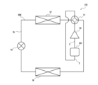
- FIG. 1 is a refrigerant circuit diagram of a refrigeration cycle device having a refrigerant storage container according to Embodiment 1.
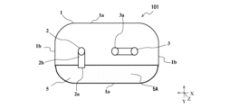
- FIG. 2 is an internal configuration diagram showing the refrigerant storage container according to Embodiment 1 from the front side.
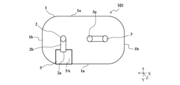
- FIG. 2 is an internal configuration diagram showing the coolant storage container according to Embodiment 1 from the top side;
- FIG. 3 is an internal configuration diagram of the refrigerant storage container viewed from direction A shown in FIG. 2 ;
- FIG. 4 is an internal configuration diagram showing a refrigerant storage container according to Modification 1 of Embodiment 1 from the front side;
- FIG. 5 is an internal configuration diagram showing the refrigerant storage container according to Modification 1 of Embodiment 1 from the top side;
- FIG. 1 is a refrigerant circuit diagram of a refrigeration cycle device having a refrigerant storage container according to Embodiment 1.
- FIG. 2 is an internal configuration diagram showing the refrigerant storage container according to Embodiment 1 from the
- FIG. 6 is an internal configuration diagram of the refrigerant storage container viewed from direction A shown in FIG. 5 ;
- FIG. 8 is an internal configuration diagram showing a refrigerant storage container according to Embodiment 2 from the front side;
- FIG. 8 is an internal configuration diagram showing a refrigerant storage container according to Embodiment 2 from the top side;
- FIG. 9 is an internal configuration diagram of the refrigerant storage container viewed from direction A shown in FIG. 8 ;
- FIG. 10 is an internal configuration diagram showing a refrigerant storage container according to Modification 1 of Embodiment 2 from the front side;
- FIG. 10 is an internal configuration diagram showing a coolant storage container according to Modification 1 of Embodiment 2 from the top side;
- FIG. 12 is an internal configuration diagram of the refrigerant storage container viewed from direction A shown in FIG. 11;
- FIG. 11 is an internal configuration diagram showing a refrigerant storage container according to Embodiment 3 from the front side;
- FIG. 11 is an internal configuration diagram showing a refrigerant storage container according to Embodiment 3 from the upper surface side;
- FIG. 15 is an internal configuration diagram of the refrigerant storage container viewed from the direction A shown in FIG. 14;
- FIG. 11 is an internal configuration diagram showing a refrigerant storage container according to Modification 1 of Embodiment 3 from the front side;
- FIG. 11 is an internal configuration diagram showing a coolant storage container according to Modification 1 of Embodiment 3 from the top side;
- FIG. 18 is an internal configuration diagram of the refrigerant storage container viewed from direction A shown in FIG. 17;
- FIG. 11 is an internal configuration diagram showing a refrigerant storage container according to Embodiment 4 from the front side;
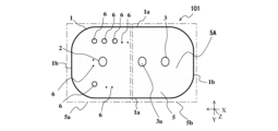
- FIG. 11 is an internal configuration diagram showing a coolant storage container according to Embodiment 4 from the top side;
- FIG. 21 is an internal configuration diagram of the refrigerant storage container viewed from direction A shown in FIG. 20;
- FIG. 11 is an internal configuration diagram showing a refrigerant storage container according to Modification 1 of Embodiment 4 from the front side;
- FIG. 11 is an internal configuration diagram showing a coolant storage container according to Modification 1 of Embodiment 4 from the top side;
- FIG. 24 is an internal configuration diagram of the refrigerant storage container viewed from the direction A shown in FIG. 23;
- a refrigerant storage container according to the present embodiment and a refrigeration cycle apparatus including the refrigerant storage container will be described below with reference to the drawings.
- the present disclosure is not limited to the following embodiments, and various modifications can be made without departing from the gist of the present disclosure.
- the present disclosure includes all combinations of configurations that can be combined among the configurations shown in the following embodiments and modifications.
- the refrigerant storage container and the refrigeration cycle device shown in the drawings show an example of the configuration, and the configuration of the present disclosure is not limited by the refrigerant storage container and the refrigeration cycle device shown in the drawings.
- terms representing directions for example, “up”, “down”, “right”, “left”, “front”, “back”, etc.) are used as appropriate for ease of understanding. They are intended to be illustrative and not limiting of the present disclosure.
- the same reference numerals are the same or equivalent, and this is common throughout the specification.
- the relative dimensional relationship, shape, etc. of each component may differ from the actual one.
- the X direction indicates the horizontal direction of the refrigerant storage container, and the arrow indicates the direction from right to left.
- the Y direction indicates the front-to-rear direction of the refrigerant storage container, and the arrow indicates the front-to-rear direction.
- the Z direction indicates the vertical direction of the refrigerant storage container, and the arrow indicates the upward direction from the bottom.
- the Z direction is the vertical direction.
- FIG. 1 is a refrigerant circuit diagram of a refrigeration cycle device 100 having a refrigerant storage container 101 according to Embodiment 1.
- a refrigeration cycle apparatus 100 according to Embodiment 1 includes a compressor 10, a flow path switching device 11, an outdoor heat exchanger 12, an expansion mechanism 13, an indoor heat exchanger 14, and a refrigerant storage container 101 .
- Compressor 10 , flow switching device 11 , outdoor heat exchanger 12 , expansion mechanism 13 , indoor heat exchanger 14 , and refrigerant reservoir 101 are connected by refrigerant pipe 15 .
- a refrigerant circuit 200 is formed in which the refrigerant circulates through the refrigerant pipe 15 .
- the refrigerant storage container 101 is connected to the compressor 10 via the outflow pipe 3 that is part of the refrigerant pipe 15 .
- the compressor 10 compresses the sucked refrigerant and discharges it in a high-temperature and high-pressure state.
- Compressor 10 is, for example, an inverter compressor.
- the refrigerant discharged from the compressor 10 flows into the outdoor heat exchanger 12 or the indoor heat exchanger 14 via the flow switching device 11 .
- the channel switching device 11 has a function of switching the coolant channel. Cooling and heating are switched by the channel switching device 11 .
- cooling operation the refrigerant discharged from the compressor 10 flows through the outdoor heat exchanger 12, the expansion mechanism 13, the indoor heat exchanger 14, and the refrigerant storage container 101 in order, and returns to the compressor 10.
- heating operation the refrigerant discharged from the compressor 10 flows through the indoor heat exchanger 14 , the expansion mechanism 13 , the outdoor heat exchanger 12 and the refrigerant storage container 101 in order, and returns to the compressor 10 . That is, during indoor cooling, the outdoor heat exchanger 12 functions as a condenser, and the indoor heat exchanger 14 functions as an evaporator.
- the indoor heat exchanger 14 functions as a condenser
- the outdoor heat exchanger 12 functions as an evaporator.
- the channel switching device 11 is, for example, a four-way valve.
- the channel switching device 11 may be configured by combining two-way valves or three-way valves.
- the expansion mechanism 13 is a decompression device that decompresses and expands the refrigerant flowing through the refrigerant circuit 200 .
- the expansion mechanism 13 is, for example, an electronic expansion valve whose opening is variably controlled.
- the refrigerant sucked into the compressor 10 is ideally a superheated gas.
- the state of the refrigerant sucked into the compressor 10 depends on the refrigerant distribution within the refrigerant circuit 200 . Therefore, refrigerant containing liquid refrigerant may be sucked into the compressor 10 .
- the refrigerant storage container 101 is installed on the upstream side of the compressor 10 in the refrigerant flow direction.
- the gas-liquid two-phase refrigerant that has flowed out of the evaporator and passed through the flow path switching device 11 flows into the refrigerant storage container 101 from the inflow pipe 2 that is a part of the refrigerant pipe 15 .
- the gas-liquid two-phase refrigerant that has flowed into the refrigerant storage container 101 is separated into gas refrigerant and liquid refrigerant, and the liquid refrigerant stays in the refrigerant storage container.
- Gas refrigerant flows out of the refrigerant storage container 101 through the outflow pipe 3 and is sucked into the compressor 10 .
- the liquid refrigerant is separated from the gas-liquid two-phase refrigerant and stored in the refrigerant storage container 101, so that the suction of the liquid refrigerant into the compressor 10 can be suppressed. .
- the refrigeration cycle device 100 is not limited to an air conditioner capable of switching between cooling and heating operations as described above.
- the refrigerant storage container 101 may be applied to refrigeration cycle devices such as dehumidifiers and refrigerator-freezers.
- FIG. 2 is an internal configuration diagram showing the refrigerant storage container 101 according to Embodiment 1 from the front side. Solid-line arrows shown in FIG. 2 conceptually indicate the flow of the refrigerant.
- FIG. 3 is an internal configuration diagram showing the refrigerant storage container 101 according to Embodiment 1 from the top side. In FIG. 3, the baffle plate 5 is indicated by a dot pattern.
- FIG. 4 is an internal configuration diagram of the refrigerant storage container 101 viewed from direction A shown in FIG. The dashed arrows shown in FIG. 4 conceptually indicate the flow of the liquid refrigerant 4 .
- the A direction corresponds to the longitudinal direction of the container body 1 and is the same direction as the X direction.
- the refrigerant storage container 101 includes a container body 1, an inflow pipe 2, an outflow pipe 3, and a baffle plate 5.
- the container body 1 is of a horizontal type having a cylindrical body portion 1a.
- the refrigerant storage container 101 is installed such that the longitudinal direction of the trunk portion 1a of the container body 1 is horizontal.
- a liquid refrigerant 4 flowing in from the inflow pipe 2 is stored in the container body 1 .
- the trunk portion 1a of the container body 1 has an arc-shaped cross section in the vertical direction.
- the container body 1 has a body portion 1a whose cross-sectional shape is a perfect circle.
- the cross-sectional shape of the trunk portion 1a of the container body 1 is not limited to a perfect circle. Although not shown, the cross-sectional shape of the trunk portion 1a of the container body 1 may be elliptical. Moreover, the cross section of the trunk portion 1a of the container body 1 may be a rounded quadrangular shape with rounded corners. Further, the end portions 1b of the container body 1 provided at both ends in the longitudinal direction of the body portion 1a are arc-shaped. As shown in FIG. 2, when the refrigerant storage container 101 is viewed from the front, the upper and lower corners of the end portion 1b of the container body 1 are arcuate. As shown in FIG.
- the front and rear corners of the end portion 1b of the container body 1 are arcuate. 2 and 3, the end portion 1b is partially linear, but the end portion 1b need not have a linear portion and may be crown-shaped.
- the inflow pipe 2 and the outflow pipe 3 are inserted into the upper part of the container body 1 .
- the inflow pipe 2 and the outflow pipe 3 are inserted from the top surface of the container body 1 .
- the inflow pipe 2 and the outflow pipe 3 do not have to be inserted from the top surface of the container main body 1 because they need only be inserted into the upper part of the container main body 1 .
- the inflow pipe 2 and the outflow pipe 3 may be inserted from any of the front, rear, left, and right surfaces of the container body 1 .
- the refrigerant in a gas-liquid two-phase state passes through the inflow pipe 2 and flows into the container body 1 from the inflow port 2 a of the inflow pipe 2 .
- the liquid refrigerant 4 that has flowed in from the inlet 2a falls to the bottom surface of the container body 1 due to gravity and stays in the container body 1.
- the gas refrigerant that has flowed into the container body 1 through the inlet 2a flows into the outlet pipe 3 through the outlet 3a.
- the gas refrigerant flowing into the outflow pipe 3 flows out of the container body 1 through the outflow pipe 3 and is sucked into the compressor 10 .
- the inflow port 2a of the inflow pipe 2 faces in directions other than the vertically upward direction and the vertically downward direction. That is, the inlet 2a opens toward the inner wall of the container body 1 at a position inclined with respect to the top of the bottom surface and the top of the container body 1 .
- the inlet 2a may be oriented horizontally, or may be oriented obliquely upward or obliquely downward with respect to the horizontal direction.
- a mode in which the inlet 2a faces in directions other than the vertically upward direction and the vertically downward direction is expressed as the inlet 2a facing sideways. 2 to 4, the inlet 2a faces the inner wall on the front side of the body portion 1a. Further, as shown in FIGS.
- the inflow pipe 2 has a curved bent portion 2b.
- the inlet 2a is positioned at the tip of the bent portion 2b.
- the inflow pipe 2 need not have the bent portion 2b.
- Figures 2-4 show an outflow tube 3 having a U-shape.
- the outflow tube 3 need not have a U-shape and may be linear.
- FIGS. 3 and 4 when the container body 1 is seen through in the longitudinal direction (X direction), the inflow pipe 2 and the outflow pipe 3 partially overlap.
- the positional relationship between the inflow pipe 2 and the outflow pipe 3 is not limited as long as the outflow port 3a is located above the inflow port 2a in the container body 1 .
- the baffle plate 5 has a plate-like shape having flat portions, and the flat portion having the largest area among the flat portions is the first flat plate surface 5A.
- the baffle plate 5 is provided inside the container body 1 and positioned below the inflow port 2a and the outflow port 3a.
- the baffle plate 5 is cantilevered on the inner wall of the container body 1 .
- the state in which the baffle plate 5 is supported in a cantilever manner on the inner wall of the container body 1 means that a part of the plate thickness surface of the baffle plate 5 is connected to the inner wall of the container body 1, and the connected plate thickness surface The other end of is a free end.
- the baffle plate 5 Since the baffle plate 5 is positioned below the inflow port 2a and the outflow port 3a, the baffle plate 5 is not supported by the inner wall of the top surface of the container body 1. As shown in FIG. In other words, the baffle plate 5 is supported by the inner wall of the container body 1 excluding the top surface. Also, the baffle plate 5 is provided so that the first flat plate surface 5A faces the liquid refrigerant 4 that flows in from the inlet 2a and flows along the inner wall. Therefore, the liquid refrigerant 4 flowing along the inner wall of the container body 1 collides with the first flat plate surface 5A of the baffle plate 5 .
- the baffle plate 5 of this embodiment is provided along the longitudinal direction of the container body 1, as shown in FIGS.
- the baffle plate 5 protrudes from the inner wall of the trunk portion 1a so that the first flat plate surface 5A is horizontal. Note that the baffle plate 5 is not necessarily provided so that the first flat plate surface 5A is horizontal.
- the baffle plate 5 may radially protrude from the inner wall of the body portion 1a. Further, as will be described in a third embodiment described later, the first flat plate surface 5A may protrude from the inner wall of the trunk portion 1a so as to be vertical.
- the baffle plate 5 of the present embodiment as shown in FIG. 4, the liquid refrigerant 4 flowing from the inlet 2a and flowing downward along the inner wall of the body portion 1a faces the first flat plate surface 5A. position. 3 and 4, the baffle plate 5 extends to a position overlapping the inlet 2a when the container body 1 is seen through in the vertical direction.
- the liquid refrigerant 4 flowing in from the inlet 2 a collides with the inner wall of the body portion 1 a facing it, flows downward along the inner wall, and collides with the first flat plate surface 5 A of the baffle plate 5 . Since the liquid refrigerant 4 flowing from the inlet 2a collides with the baffle plate 5 and loses momentum, scattering of the liquid refrigerant 4 generated when it collides with the liquid refrigerant 4 stagnating in the container body 1 is suppressed.
- Refrigerant storage container 101 includes a horizontally placed container body 1 having a cylindrical body portion 1a for storing a refrigerant containing liquid refrigerant 4, and a container body 1 inserted into the container body 1 to store the refrigerant.
- a baffle plate 5 that is cantilevered on the inner wall of the main body 1 is provided.
- the inlet 2a is provided laterally so as to face the inner wall, and in the container body 1, the outlet 3a is positioned above the inlet 2a, and the baffle plate 5 is positioned below the inlet 2a.
- the liquid refrigerant 4 flowing in from the inlet 2a and flowing along the inner wall faces the first flat plate surface 5A.
- the container main body 1 is of the horizontal type, the height of the refrigerant storage container 101 can be reduced. Also, the liquid refrigerant 4 flowing from the inlet 2 a flows along the inner wall of the container body 1 and collides with the first flat plate surface 5 A of the baffle plate 5 . Therefore, scattering of the liquid refrigerant 4 staying in the container body 1 caused by the liquid refrigerant 4 flowing along the inner wall can be suppressed. Therefore, even if the container main body 1 is of a horizontal type in which the stagnant liquid refrigerant 4 is violently swirled up, it is possible to suppress the liquid refrigerant 4 from flowing out from the outflow pipe 3 .
- the inlet 2a is opened so as to face the inner wall of the body portion 1a among the inner walls, and the baffle plate 5 is provided on the inner wall of the body portion 1a. Supported.
- the baffle plate 5 is provided at a position where the liquid refrigerant 4 flowing downward along the inner wall of the body portion 1a faces the first flat plate surface 5A.
- This configuration increases the possibility that the liquid refrigerant 4 that has flowed in from the inlet 2 a collides with the first flat plate surface 5 A of the baffle plate 5 . Therefore, the momentum of the flow of the liquid refrigerant 4 flowing in from the inlet 2a is reduced, and the waving of the liquid refrigerant 4 staying in the container body 1 is suppressed. Therefore, scattering of the liquid refrigerant 4 staying in the container main body 1 can be suppressed.
- the baffle plate 5 is supported by the inner wall so that the first flat plate surface 5A is horizontal. According to this configuration, the liquid refrigerant 4 flowing from the inflow port 2a and flowing along the inner wall of the container body 1 flows horizontally when it collides with the first flat plate surface 5A. mitigated. Therefore, the liquid refrigerant 4 staying in the container body 1 is suppressed from waving, and the scattering of the liquid refrigerant 4 can be suppressed.
- the baffle plate 5 is provided over both ends in the longitudinal direction of the body portion 1a. According to this configuration, the liquid refrigerant 4 flowing in from the inlet 2a is more likely to collide with the first flat plate surface 5A of the baffle plate 5 and the momentum of the flow is reduced. Therefore, the possibility of suppressing the waving of the liquid refrigerant 4 staying in the container body 1 and the possibility of suppressing the scattering of the liquid refrigerant 4 also increase.
- the configuration of the refrigeration cycle apparatus 100 includes the refrigerant storage container 101 and the compressor 10 connected to the refrigerant storage container 101 via the outflow pipe 3 . According to this configuration, it is possible to prevent the liquid refrigerant 4 from being sucked into the compressor 10 from the refrigerant storage container 101 through the outflow pipe 3 . Therefore, it is possible to reduce the possibility that the refrigerating machine oil of the compressor 10 is diluted and seizure of the sliding portion of the compressor occurs.
- FIG. 5 is an internal configuration diagram showing the refrigerant storage container 101 according to Modification 1 of Embodiment 1 from the front side. Solid-line arrows shown in FIG. 5 conceptually indicate the flow of the refrigerant.
- FIG. 6 is an internal configuration diagram showing the refrigerant storage container 101 according to Modification 1 of Embodiment 1 from the top side. In FIG. 6, the baffle plate 5 is indicated by a dot pattern.
- FIG. 7 is an internal configuration diagram of the refrigerant storage container 101 viewed from direction A shown in FIG. The dashed arrows shown in FIG.
- 7 conceptually indicate the flow of the liquid refrigerant 4 .
- 7 and 4 are views of the refrigerant storage container 101 viewed from the direction A, so they look the same, but the length of the baffle plate 5 in the direction A is different. Note that the A direction corresponds to the longitudinal direction of the container body 1 .
- the length in the longitudinal direction of the baffle plate 5 is different from the length in the longitudinal direction of the baffle plate 5 in the first embodiment.
- the baffle plate 5 in Modification 1 is partially provided in the longitudinal direction of the container body 1, as shown in FIGS. In the longitudinal direction of the container body 1, the length of the baffle plate 5 is shorter than the length of the inner wall supporting the baffle plate 5 of the body portion 1a.
- the baffle plate 5 in Modification 1 is provided at a position where the liquid refrigerant 4 flowing downward along the inner wall of the body portion 1a faces the first flat plate surface 5A.
- the baffle plate 5 extends to a position overlapping the inlet 2a. Therefore, as shown in FIG. 7, the liquid refrigerant 4 flowing from the inlet 2a collides with the inner wall of the body portion 1a, and then flows downward along the inner wall. Then, the liquid refrigerant 4 collides with the baffle plate 5 provided below the inlet 2a.
- the baffle plate 5 in Modification 1 can reduce the momentum of the liquid refrigerant 4 flowing in from the inlet 2a.
- the baffle plate 5 in Modification 1 can reduce the momentum of the liquid refrigerant 4 flowing in from the inlet 2a.
- the liquid refrigerant 4 that has flowed in from the inlet 2a collides with the liquid refrigerant 4 that has accumulated in the container body 1, scattering of the refrigerant from the liquid surface is suppressed.
- the difference between Modification 1 and Embodiment 1 is only the length in the longitudinal direction of the baffle plate 5, and other configurations and functions are the same as those of Embodiment 1. Therefore, here, The explanation is omitted.
- the baffle plate 5 partially provided in the longitudinal direction of the container body 1 can reduce the momentum of the liquid refrigerant 4 flowing into the container body 1 . Therefore, scattering of the liquid refrigerant 4 from the liquid surface of the liquid refrigerant 4 is suppressed. Therefore, in the configuration of the refrigerant storage container 101 according to Modification 1, it is possible to reduce the materials constituting the refrigerant storage container 101 and to provide the refrigerant storage container 101 capable of suppressing the scattered liquid refrigerant 4 from reaching the refrigerant outflow pipe. It is possible to achieve both
- Embodiment 2 A refrigerant storage container 101 according to Embodiment 2 will be described.
- a difference between the present embodiment and the first embodiment is the positional relationship between the baffle plate 5 and the inlet 2a.
- the positional relationship between the baffle plate 5 and the inlet 2a of this embodiment will be described below, focusing on the differences from the first embodiment.
- the configurations of the refrigerant storage container 101 and the refrigerating cycle device 100 of the present embodiment are the same as those of the first embodiment, and thus description thereof is omitted.
- the same reference numerals are given to the same components as those in the first embodiment, and the description thereof will be omitted as appropriate.
- FIG. 8 is an internal configuration diagram showing the refrigerant storage container 101 according to Embodiment 2 from the front side. Solid-line arrows shown in FIG. 8 conceptually indicate the flow of the refrigerant.
- FIG. 9 is an internal configuration diagram showing the refrigerant storage container 101 according to Embodiment 2 from the top side. In FIG. 9, the baffle plate 5 is indicated by a dot pattern.
- FIG. 10 is an internal configuration diagram of the refrigerant storage container 101 viewed from direction A shown in FIG. The dashed arrows shown in FIG. 10 conceptually indicate the flow of the liquid refrigerant 4 . Note that the A direction corresponds to the longitudinal direction of the container body 1 .
- the baffle plate 5 is provided on the inner wall of the body portion 1a along the longitudinal direction of the container body 1 in the same manner as the baffle plate 5 in the first embodiment.
- one longitudinal thick plate surface of the baffle plate 5 is supported by the inner wall of the trunk portion 1a.
- the location of the inner wall where the baffle plate 5 is cantilevered differs between the present embodiment and the first embodiment.
- the liquid refrigerant 4 that flows in from the inlet 2a and flows upward along the inner wall of the body portion 1a collides with the first flat plate surface 5A. It is provided at a position where
- the baffle plate 5 protrudes from the inner wall of the trunk portion 1a so that the first flat plate surface 5A is horizontal.
- the baffle plate 5 is provided at a position where the liquid refrigerant 4 flowing from the inlet 2a and flowing upward along the inner wall of the body portion 1a collides with the first flat plate surface 5A.
- the baffle plate 5 protrudes from the inner wall of the body portion 1a opposite to the inner wall of the body portion 1a facing the inlet 2a.
- the baffle plate 5 is provided on the rear inner wall of the container body 1 when the inner wall of the body portion 1a facing the inlet 2a is the front inner wall of the container body 1.
- FIGS. When the container body 1 is seen through in the vertical direction, the baffle plate 5 and the inlet 2a do not overlap.
- the liquid refrigerant 4 flowing from the inlet 2a collides with the inner wall of the body portion 1a facing the inlet 2a, flows downward along the inner wall, and remains in the container body 1. Flow into 4.
- the stagnant liquid refrigerant 4 may be attracted by the flow of the liquid refrigerant 4 flowing along the inner wall, and the liquid level on the rear surface side of the container body 1 may rise along the inner wall.
- the baffle plate 5 in this embodiment is provided on the inner wall on the rear surface side of the container body 1 , the liquid surface rising along the inner wall is the first It collides with the flat plate surface 5A. Therefore, the rise in the liquid level of the liquid refrigerant 4 caused by the inflow of the liquid refrigerant 4 from the inlet 2a into the liquid refrigerant 4 stagnating in the container main body 1 is suppressed.
- the baffle plate 5 is provided at a position where the liquid refrigerant 4 flowing upward along the inner wall of the body faces the first flat plate surface 5A.
- the baffle plate 5 suppresses an increase in the liquid level of the liquid refrigerant 4 stagnant in the container body 1, thereby suppressing the stagnant liquid refrigerant 4 from being swirled up. As a result, the generation of the liquid refrigerant 4 that scatters from the liquid surface is also suppressed.
- FIG. 11 is an internal configuration diagram showing the refrigerant storage container 101 according to Modification 1 of Embodiment 2 from the front side. Solid-line arrows shown in FIG. 11 conceptually indicate the flow of the refrigerant.
- FIG. 12 is an internal configuration diagram showing the coolant storage container 101 according to Modification 1 of Embodiment 2 from the top side. In FIG. 12, the baffle plate 5 is indicated by a dot pattern.
- FIG. 13 is an internal configuration diagram of the refrigerant storage container 101 viewed from direction A shown in FIG. The dashed arrows shown in FIG.
- 13 conceptually indicate the flow of the liquid refrigerant 4 .
- 13 and 10 are views of the refrigerant storage container 101 viewed from the direction A, so they look the same, but the length of the baffle plate 5 in the direction A is different. Note that the A direction corresponds to the longitudinal direction of the container body 1 .
- the longitudinal length of the baffle plate 5 is different from the longitudinal length of the baffle plate 5 in the second embodiment.
- the baffle plate 5 in Modification 1 is partially provided in the longitudinal direction of the container body 1 as shown in FIGS. 10 and 11 .
- the length of the baffle plate 5 is shorter than the length of the inner wall supporting the baffle plate 5 of the body portion 1a.
- the baffle plate 5 in Modification 1 is provided at a position where the liquid refrigerant 4 flowing upward along the inner wall of the body portion 1a faces the first flat plate surface 5A. Further, as shown in FIGS. 12 and 13, when the container body 1 is seen through in the vertical direction, the baffle plate 5 and the inlet 2a do not overlap. Assuming that the liquid refrigerant 4 does not stay in the container body 1 and that the momentum of the liquid refrigerant 4 flowing in from the inlet 2a is not relieved, the baffle plate 5 flows in from the inlet 2a to the inner wall. It is provided so that the liquid refrigerant 4 flowing upward along it collides with the first flat plate surface 5A. For this reason, as shown in FIG.
- the baffle plate 5 partially provided on the rear surface side of the container body 1 can reduce the force of the inflowing liquid refrigerant 4 . Therefore, as in the second embodiment, it is possible to suppress the scattering of the liquid refrigerant 4 when the liquid refrigerant 4 collides with the baffle plate 5 and the scattering of the liquid refrigerant 4 due to the swelling of the stagnant liquid refrigerant 4. . Therefore, in the configuration of the refrigerant storage container 101 according to Modification 1, it is possible to reduce the materials constituting the refrigerant storage container 101 and to provide the refrigerant storage container 101 capable of suppressing the scattered liquid refrigerant 4 from reaching the refrigerant outflow pipe. It is possible to achieve both
- Embodiment 3 A refrigerant storage container 101 according to Embodiment 3 will be described.
- the difference between the present embodiment and the first and second embodiments is the manner in which the baffle plate 5 is installed.
- the installation mode of the baffle plate 5 of the present embodiment will be described, focusing on the differences from the first and second embodiments.
- the configurations of the refrigerant storage container 101 and the refrigeration cycle device 100 of the present embodiment are the same as those of the first and second embodiments, except for the manner in which the baffle plate 5 is installed.
- the same reference numerals are given to the same components as those in the first embodiment, and the description thereof will be omitted as appropriate.
- FIG. 14 is an internal configuration diagram showing the refrigerant storage container 101 according to Embodiment 3 from the front side. Solid-line arrows shown in FIG. 14 conceptually indicate the flow of the refrigerant. Also, in FIG. 14, the baffle plate 5 is indicated by a dot pattern.
- FIG. 15 is an internal configuration diagram showing the refrigerant storage container 101 according to Embodiment 3 from the top side.
- FIG. 16 is an internal configuration diagram of the refrigerant storage container 101 viewed from direction A shown in FIG. The dashed arrows shown in FIG. 16 conceptually indicate the flow of the liquid refrigerant 4 . Note that the A direction corresponds to the longitudinal direction of the container body 1 .
- the baffle plate 5 is provided vertically on the inner wall of the bottom surface of the container body 1 .
- the baffle plate 5 is cantilevered on the inner wall of the trunk portion 1a of the container body 1 so that the first flat plate surface 5A is vertical.
- the baffle plate 5 is provided along the longitudinal direction of the container body 1 on the inner wall at the lowest position of the body portion 1 a corresponding to the bottom surface of the container body 1 .
- One longitudinal plate thickness surface of the baffle plate 5 is supported by the lowest inner wall of the body portion 1a.
- the length of the baffle plate 5 is equal to the length of the inner wall supporting the baffle plate 5 of the trunk portion 1a.
- the baffle plate 5 is provided on the front side of the outflow pipe 3 in the front-rear direction (Y direction) of the container body 1 .
- the positional relationship between the baffle plate 5 and the outflow pipe 3 is not limited as long as the outflow port 3a is located above the baffle plate 5 in the container body 1 .
- the inflow pipe 2 and the outflow pipe 3 do not overlap.
- the positional relationship between the inflow pipe 2 and the outflow pipe 3 is not limited as long as the outflow port 3a is located above the inflow port 2a in the container body 1 .
- the baffle plate 5 does not overlap the inlet 2a when the container body 1 is seen through in the vertical direction. However, as described in Embodiment 1, if the baffle plate 5 is located below the inlet 2a in the container body 1, there is no restriction on the positional relationship between the baffle plate 5 and the inlet 2a. When the container main body 1 is seen through in the vertical direction, the baffle plate 5 and the inlet 2a may be provided at overlapping positions. In addition, in the front-rear direction of the container body 1, the baffle plate 5 may be positioned either on the front side or the rear side of the inlet 2a.
- the liquid refrigerant 4 flowing from the inlet 2a collides with the inner wall of the body portion 1a facing the inlet 2a, flows downward along the inner wall, and remains in the container body 1. Flow into 4.
- the stagnant liquid refrigerant 4 may be attracted by the flow of the liquid refrigerant 4 flowing along the inner wall, and the liquid level on the rear surface side of the container body 1 may rise along the inner wall.
- the baffle plate 5 in this embodiment is provided so that the first flat plate surface 5A is vertical to the bottom surface of the container body 1, the liquid refrigerant 4 flowing along the inner wall as shown in FIG. , collide with the first flat plate surface 5 A of the baffle plate 5 . Therefore, the rise in the liquid level of the liquid refrigerant 4 caused by the inflow of the liquid refrigerant 4 from the inlet 2 a into the liquid refrigerant 4 stagnating in the container body 1 is suppressed.
- the baffle plate 5 is supported by the inner wall so that the first flat plate surface 5A is vertical.
- FIG. 17 is an internal configuration diagram showing the refrigerant storage container 101 according to Modification 1 of Embodiment 3 from the front side. Solid-line arrows shown in FIG. 17 conceptually indicate the flow of the refrigerant. Also, in FIG. 17, the baffle plate 5 is indicated by a dot pattern.
- FIG. 18 is an internal configuration diagram showing the refrigerant storage container 101 according to Modification 1 of Embodiment 3 from the top side.
- FIG. 19 is an internal configuration diagram of the refrigerant storage container 101 viewed from direction A shown in FIG. The dashed arrows shown in FIG.
- 19 conceptually indicate the flow of the liquid refrigerant 4 .
- 19 and 16 are views of the refrigerant storage container 101 viewed from the direction A, so they look the same, but the length of the baffle plate 5 in the direction A is different. Note that the A direction corresponds to the longitudinal direction of the container body 1 .
- the length of the baffle plate 5 in the longitudinal direction is different from the length of the baffle plate 5 in the longitudinal direction of the third embodiment.
- the baffle plate 5 in Modification 1 is partially provided on the bottom surface of the container body 1 as shown in FIGS. 17 and 18 .
- the length of the baffle plate 5 in the longitudinal direction of the container body 1 is shorter than the length of the inner wall of the body portion 1a that supports the baffle plate 5 .
- the baffle plate 5 is provided at a position where the first flat plate surface 5A faces the liquid refrigerant 4 that flows in from the inlet 2a and flows along the inner wall. Assuming that the liquid refrigerant 4 does not stay in the container body 1 and that the momentum of the liquid refrigerant 4 flowing in from the inlet 2a is not relieved, the baffle plate 5 flows in from the inlet 2a to the inner wall. It is provided so that the liquid refrigerant 4 flowing along collides with the first flat plate surface 5A. Therefore, as shown in FIG. 19 , the liquid refrigerant 4 flowing from the inlet 2 a and flowing along the inner wall collides with the first flat plate surface 5 A of the baffle plate 5 .
- the liquid surface of the liquid refrigerant 4 is attracted by the liquid refrigerant 4 that flows in from the inlet 2a and flows along the inner wall. increase can be suppressed.
- Modification 1 and Embodiment 3 is only the length in the longitudinal direction of the baffle plate 5, and other configurations and functions are the same as those of Embodiment 3. Therefore, here, The explanation is omitted.
- Embodiment 4 A refrigerant storage container 101 according to Embodiment 4 will be described.
- the difference between the present embodiment and the first to third embodiments is the installation mode and configuration of the baffle plate 5 .
- the installation mode and configuration of the baffle plate 5 of the present embodiment will be described below, focusing on differences from the first to third embodiments.
- the configurations of the refrigerant storage container 101 and the refrigerating cycle device 100 of the present embodiment are the same as those of the first and second embodiments except for the installation mode and configuration of the baffle plate 5, and thus description thereof is omitted.
- the same reference numerals are given to the same components as those in the first embodiment, and the description thereof will be omitted as appropriate.
- FIG. FIG. 20 is an internal configuration diagram showing the refrigerant storage container 101 according to Embodiment 4 from the front side. Solid-line arrows shown in FIG. 20 conceptually indicate the flow of the refrigerant.
- FIG. 21 is an internal configuration diagram showing the refrigerant storage container 101 according to Embodiment 3 from the top side. In FIG. 21, the baffle plate 5 is indicated by a dot pattern.
- FIG. 22 is an internal configuration diagram of the refrigerant storage container 101 viewed from direction A shown in FIG. The dashed arrows shown in FIG. 22 conceptually indicate the flow of the liquid refrigerant 4 . Note that the A direction corresponds to the longitudinal direction of the container body 1 .
- the baffle plate 5 is provided so that the plate thickness surface is supported by the inner wall of the container body 1 and the first flat plate surface 5A is horizontal. As shown in FIGS. 20 and 22, the internal space of the container body 1 is divided by the baffle plate 5 into an upper space and a lower space. In the vertical direction (Z direction) of the container body 1, the baffle plate 5 is provided so as to be positioned between the outflow port 3a and the inflow port 2a. Therefore, the outflow port 3a is located above the baffle plate 5, but the inflow port 2a is located below the baffle plate 5. As shown in FIGS. 20 and 22, the inflow pipe 2 and the outflow pipe 3 can be provided through the baffle plate 5 .
- the baffle plate 5 Since the internal space of the container body 1 is divided into an upper space and a lower space by the baffle plate 5, the gas refrigerant flowing into the container body 1 from the inlet 2a located in the lower space of the baffle plate 5 flows into the upper space of the baffle plate 5. cannot reach the outflow port 3a located at .
- the baffle plate 5 is provided with at least one through hole 6 for allowing the gaseous refrigerant, which has flowed into the lower space from the inlet 2a, to move to the upper space. Since the gas refrigerant that has flowed into the lower space from the inlet 2 a can move to the upper space through the through hole 6 , it flows into the outlet pipe 3 through the outlet 3 a and out of the container body 1 .
- the liquid refrigerant 4 flowing from the inlet 2a collides with the inner wall of the body portion 1a facing the inlet 2a, flows downward along the inner wall, and stays in the container body 1. It flows into the liquid refrigerant 4 . Attracted by the flow of the liquid refrigerant 4 flowing along the inner wall, the liquid surface of the liquid refrigerant 4 on the rear surface side of the container body 1 may rise along the inner wall.
- the baffle plate 5 in this embodiment is provided horizontally so as to partition the internal space of the container body 1, as shown in FIG. collides with the first flat plate surface 5A.
- the rise in the liquid level of the liquid refrigerant 4 caused by the inflow of the liquid refrigerant 4 from the inlet 2 a into the liquid refrigerant 4 stagnating in the container body 1 is suppressed.
- the generation of the liquid refrigerant 4 that scatters from the rising liquid surface is also suppressed.
- the liquid refrigerant 4 scattered from the liquid surface is blocked by the baffle plate 5, it cannot reach the outflow port 3a. Therefore, the liquid refrigerant 4 is suppressed from flowing out of the container body 1 through the outflow pipe 3 .
- the through holes 6 There may be a plurality of through holes 6 as shown in FIG. 21, and the number is not limited. Although the through holes 6 are indicated by white circles and black dots in FIG. 21, the position, opening area, and number of the through holes 6 are not limited by these white circles and black dots. In relation to the total opening area of the through holes 6, the opening area of the inlet 2a, and the opening area of the outlet 3a, the total opening area of the through holes 6 is never the smallest. Moreover, the total opening area of the through holes 6 need not be the largest in relation to the total opening area of the through holes 6, the opening area of the inflow port 2a, and the opening area of the outflow port 3a.
- the total opening area of the through-holes 6 is the opening area of one through-hole 6 when only one through-hole 6 is provided, and the total opening area of each through-hole 6 when a plurality of through-holes 6 is provided. It is the area obtained by adding all the opening areas of 6. There is no particular limitation on the relationship between the opening area of the inlet 2a and the opening area of the outlet 3a. Each opening area of the inflow port 2a and the outflow port 3a may be equal, or one of them may have a larger opening area.
- the total opening area of the through holes 6 is S1, the opening area of the inlet 2a is S2, and the opening area of the outlet 3a is S3. , and the opening area S3 of the outflow port 3a.
- the opening area S2 of the inflow port 2a and the opening area S3 of the outflow port 3a have a relationship of S2 ⁇ S3
- the total opening area S1 of the through-holes 6 cannot be smaller than S2, so the relationship of S1>S2.
- the opening area S2 of the inlet 2a and the opening area S3 of the outlet 3a have a relationship of S3 ⁇ S2
- the total opening area S1 of the through holes 6 cannot be smaller than S3, so the relationship of S1>S3 is satisfied.
- Refrigerant storage container 101 includes a horizontally placed container body 1 having a cylindrical body portion 1a and storing a refrigerant including a gaseous refrigerant; 1, an outflow pipe 3 inserted into the container body 1 and having an outflow port 3a through which the refrigerant flows out from the container body 1, and a container body having a first flat plate surface 5A.
- a baffle plate 5 having a plate thickness surface supported by the inner wall of the baffle plate 1 is provided.
- the inlet 2a is provided laterally so as to face the inner wall.
- the outlet 3a is positioned above the inlet 2a and the baffle plate 5, and the baffle plate 5 is located above the inlet 2a.
- a first flat plate surface 5A is provided so as to divide the internal space of the container body 1 into an upper space and a lower space.
- the baffle plate 5 is provided with at least one through hole 6 through which the gas refrigerant passes.
- the container main body 1 is of the horizontal type, the height of the refrigerant storage container 101 can be reduced. Also, the liquid refrigerant 4 flowing from the inlet 2 a flows along the inner wall of the container body 1 and collides with the first flat plate surface 5 A of the baffle plate 5 . Therefore, scattering of the liquid refrigerant 4 staying in the container body 1 caused by the liquid refrigerant 4 flowing along the inner wall can be suppressed. In addition, since the outflow port 3a is provided above the baffle plate 5, the scattered liquid refrigerant 4 is blocked by the baffle plate 5 and is suppressed from reaching the outflow port 3a. Therefore, even if the container main body 1 is of a horizontal type in which the stagnant liquid refrigerant 4 is violently swirled up, it is possible to suppress the liquid refrigerant 4 from flowing out from the outflow pipe 3 .
- the inflow pipe 2 is provided so as to pass through the baffle plate 5 . According to this configuration, the inflow pipe 2 can be inserted into the container main body 1 from the upper space of the container main body 1, so that the refrigerant storage container 101 can be configured more freely.
- the baffle plate 5 is provided with at least one plurality of through holes 6, the total opening area of the plurality of through holes 6 is S1, and the opening of the inlet 2a is When the area is S2 and the opening area of the outlet 3a is S3, when the opening area S2 and the opening area S3 have a relationship of S2 ⁇ S3, the total opening area S1 and the opening area S2 have a relationship of S1>S2. . Further, when the opening area S2 and the opening area S3 have a relationship of S3 ⁇ S2, the total opening area S1 and the opening area S3 have a relationship of S1>S3.
- the total opening area of the through holes 6 is not the smallest in relation to the total opening area of the through holes 6, the opening area of the inlet 2a, and the opening area of the outlet 3a. Therefore, the gas refrigerant that has flowed into the lower space of the container body 1 can pass through the through holes 6 and smoothly reach the outflow port 3a.
- FIG. 23 is an internal configuration diagram showing the refrigerant storage container 101 according to Modification 1 of Embodiment 3 from the front side. Solid-line arrows shown in FIG. 23 conceptually indicate the flow of the refrigerant.
- FIG. 24 is an internal configuration diagram showing the coolant storage container 101 according to Modification 1 of Embodiment 3 from the top side.
- the baffle plate 5 is indicated by a dot pattern.
- the through-holes 6 are indicated by white circles and black dots in FIG. 24, the position, opening area, and number of the through-holes 6 are not limited by these white circles and black dots.
- FIG. 23 is an internal configuration diagram showing the refrigerant storage container 101 according to Modification 1 of Embodiment 3 from the front side. Solid-line arrows shown in FIG. 23 conceptually indicate the flow of the refrigerant.
- FIG. 24 is an internal configuration diagram showing the coolant storage container 101 according to Modification 1 of Embodiment 3 from the top side.
- the baffle plate 5 is indicated by a
- 25 is an internal configuration diagram of the refrigerant storage container 101 viewed from direction A shown in FIG.
- the dashed arrows shown in FIG. 25 conceptually indicate the flow of the liquid refrigerant 4 .
- 25 and 22 are views of the refrigerant storage container 101 viewed from the direction A, so they look the same, but the positions of the through holes 6 are different. Note that the A direction corresponds to the longitudinal direction of the container body 1 .
- the positions of the through holes 6 in the baffle plate 5 are different from the positions of the through holes 6 in the fourth embodiment.
- the difference between Modification 1 and Embodiment 4 is only the position of through-holes 6 provided in baffle plate 5, and other configurations and functions are the same as those of Embodiment 4. Therefore, here, The explanation is omitted.
- the first region 5a and the second region 5b when the baffle plate 5 is divided into two equal parts in the longitudinal direction of the container body 1 are indicated by dashed lines.
- the through holes 6 are provided only in the first region 5a and not provided in the second region 5b.
- the inlet 2a is the second region.
- the outlet 3a is located below the first area 5a, the outlet 3a is located above the second area 5b, and the plurality of through holes 6 are provided in the first area 5a and not provided in the second area 5b. . According to this configuration, the distance between the through hole 6 and the outflow port 3a can be ensured.
- the liquid refrigerant 4 scattered in the lower space of the baffle plate 5 moves to the upper space through the through holes 6, the liquid refrigerant 4 does not easily reach the outflow port 3a. Therefore, even if the container body 1 is of a horizontal type in which the stagnant liquid refrigerant 4 is violently swirled up, it is possible to more effectively suppress the liquid refrigerant 4 from flowing out of the outflow pipe 3 .
- Embodiments 1 to 4 and modifications have been described above, but refrigerant storage container 101 and refrigeration cycle device 100 are not limited to Embodiments 1 to 4 and modifications described above Various modifications and applications are possible without departing from the gist of the invention. That is, the refrigerant storage container 101 and the refrigeration cycle device 100 include a range of design changes and application variations that are normally made by those skilled in the art without departing from the technical idea thereof.
Landscapes
- Engineering & Computer Science (AREA)
- Physics & Mathematics (AREA)
- Mechanical Engineering (AREA)
- Thermal Sciences (AREA)
- General Engineering & Computer Science (AREA)
- Chemical & Material Sciences (AREA)
- Analytical Chemistry (AREA)
- Power Engineering (AREA)
- Other Air-Conditioning Systems (AREA)
- Compressor (AREA)
- Devices That Are Associated With Refrigeration Equipment (AREA)
Priority Applications (5)
| Application Number | Priority Date | Filing Date | Title |
|---|---|---|---|
| US18/686,919 US20240369272A1 (en) | 2021-10-29 | 2021-10-29 | Refrigerant reservoir container and refrigeration cycle apparatus including the refrigerant reservoir container |
| EP21962461.6A EP4425074A1 (en) | 2021-10-29 | 2021-10-29 | Refrigerant storage container, and refrigeration cycle device provided with said refrigerant storage container |
| CN202180103301.5A CN118103648A (zh) | 2021-10-29 | 2021-10-29 | 制冷剂储存容器和具有该制冷剂储存容器的制冷循环装置 |
| PCT/JP2021/040018 WO2023073919A1 (ja) | 2021-10-29 | 2021-10-29 | 冷媒貯留容器及び該冷媒貯留容器を備えた冷凍サイクル装置 |
| JP2023556026A JPWO2023073919A1 (https=) | 2021-10-29 | 2021-10-29 |
Applications Claiming Priority (1)
| Application Number | Priority Date | Filing Date | Title |
|---|---|---|---|
| PCT/JP2021/040018 WO2023073919A1 (ja) | 2021-10-29 | 2021-10-29 | 冷媒貯留容器及び該冷媒貯留容器を備えた冷凍サイクル装置 |
Publications (1)
| Publication Number | Publication Date |
|---|---|
| WO2023073919A1 true WO2023073919A1 (ja) | 2023-05-04 |
Family
ID=86157633
Family Applications (1)
| Application Number | Title | Priority Date | Filing Date |
|---|---|---|---|
| PCT/JP2021/040018 Ceased WO2023073919A1 (ja) | 2021-10-29 | 2021-10-29 | 冷媒貯留容器及び該冷媒貯留容器を備えた冷凍サイクル装置 |
Country Status (5)
| Country | Link |
|---|---|
| US (1) | US20240369272A1 (https=) |
| EP (1) | EP4425074A1 (https=) |
| JP (1) | JPWO2023073919A1 (https=) |
| CN (1) | CN118103648A (https=) |
| WO (1) | WO2023073919A1 (https=) |
Citations (5)
| Publication number | Priority date | Publication date | Assignee | Title |
|---|---|---|---|---|
| JPS61191843A (ja) * | 1985-02-20 | 1986-08-26 | 松下冷機株式会社 | アキユムレ−タ |
| JPH08110127A (ja) * | 1994-10-06 | 1996-04-30 | Mitsubishi Electric Corp | 冷凍サイクル用のアキュムレータ並びにその製造方法 |
| JPH08271094A (ja) * | 1995-04-04 | 1996-10-18 | Matsushita Refrig Co Ltd | アキュムレータ |
| JPH1114198A (ja) * | 1997-06-20 | 1999-01-22 | Matsushita Refrig Co Ltd | 気液分離器 |
| CN205843155U (zh) * | 2016-07-27 | 2016-12-28 | 广东美的暖通设备有限公司 | 气液分离器和具有其的空调 |
Family Cites Families (4)
| Publication number | Priority date | Publication date | Assignee | Title |
|---|---|---|---|---|
| US2830797A (en) * | 1953-05-05 | 1958-04-15 | Frick Co | Refrigerant condenser |
| US5282370A (en) * | 1992-05-07 | 1994-02-01 | Fayette Tubular Technology Corporation | Air-conditioning system accumulator and method of making same |
| PT672875E (pt) * | 1994-03-15 | 2000-11-30 | Mitsubishi Electric Corp | Sistema de ar condicionado, acumulador para o mesmo e processo para a fabricacaodo acumulador |
| AU2020248049B2 (en) * | 2019-03-22 | 2023-06-01 | Nec Corporation | Liquid separator, cooling system, and gas-liquid separation method |
-
2021
- 2021-10-29 EP EP21962461.6A patent/EP4425074A1/en not_active Withdrawn
- 2021-10-29 WO PCT/JP2021/040018 patent/WO2023073919A1/ja not_active Ceased
- 2021-10-29 CN CN202180103301.5A patent/CN118103648A/zh active Pending
- 2021-10-29 US US18/686,919 patent/US20240369272A1/en active Pending
- 2021-10-29 JP JP2023556026A patent/JPWO2023073919A1/ja active Pending
Patent Citations (6)
| Publication number | Priority date | Publication date | Assignee | Title |
|---|---|---|---|---|
| JPS61191843A (ja) * | 1985-02-20 | 1986-08-26 | 松下冷機株式会社 | アキユムレ−タ |
| JPH08110127A (ja) * | 1994-10-06 | 1996-04-30 | Mitsubishi Electric Corp | 冷凍サイクル用のアキュムレータ並びにその製造方法 |
| JP3163312B2 (ja) | 1994-10-06 | 2001-05-08 | 三菱電機株式会社 | 冷凍サイクル用のアキュムレータ並びにその製造方法 |
| JPH08271094A (ja) * | 1995-04-04 | 1996-10-18 | Matsushita Refrig Co Ltd | アキュムレータ |
| JPH1114198A (ja) * | 1997-06-20 | 1999-01-22 | Matsushita Refrig Co Ltd | 気液分離器 |
| CN205843155U (zh) * | 2016-07-27 | 2016-12-28 | 广东美的暖通设备有限公司 | 气液分离器和具有其的空调 |
Also Published As
| Publication number | Publication date |
|---|---|
| CN118103648A (zh) | 2024-05-28 |
| JPWO2023073919A1 (https=) | 2023-05-04 |
| EP4425074A1 (en) | 2024-09-04 |
| US20240369272A1 (en) | 2024-11-07 |
Similar Documents
| Publication | Publication Date | Title |
|---|---|---|
| CN107076487B (zh) | 油分离器 | |
| JP4153457B2 (ja) | 流路装置、冷凍サイクル装置 | |
| WO2010143521A1 (ja) | 冷媒圧縮機及びヒートポンプ装置 | |
| JP5826437B1 (ja) | 膨張弁、及び、冷凍サイクル装置 | |
| JP2018169062A (ja) | 空気調和機 | |
| JP5757415B2 (ja) | 空気調和機等の冷凍装置 | |
| JP2007192433A (ja) | 気液分離器及び該気液分離器を備えた冷凍装置 | |
| WO2023073919A1 (ja) | 冷媒貯留容器及び該冷媒貯留容器を備えた冷凍サイクル装置 | |
| JP4659066B2 (ja) | 流路装置 | |
| JP2006266636A (ja) | 冷凍装置 | |
| WO2023007620A1 (ja) | 冷媒貯留容器及びこの冷媒貯留容器を備えた冷凍サイクル装置 | |
| EP2910875B1 (en) | Oil separator | |
| WO2023017594A1 (ja) | 冷媒貯留容器及び該冷媒貯留容器を備えた冷凍サイクル装置 | |
| JP2006343064A (ja) | 冷凍サイクル用気液分離器 | |
| JP7430759B2 (ja) | アキュムレータ及び冷凍サイクル | |
| JP6710294B2 (ja) | 圧縮機及び冷凍サイクル装置 | |
| WO2022230101A1 (ja) | 受液器および冷凍サイクル装置 | |
| WO2017085813A1 (ja) | 空気調和装置 | |
| KR20230103967A (ko) | 차량용 어큐뮬레이터 | |
| WO2023166705A1 (ja) | 冷媒貯留容器及び該冷媒貯留容器を備えた冷凍サイクル装置 | |
| WO2024166159A1 (ja) | アキュームレータ及び冷凍サイクル装置 | |
| JP2023538064A (ja) | 冷凍システム用のアキュムレータ及び冷蔵庫 | |
| JP4623031B2 (ja) | 冷凍冷蔵庫 | |
| JP7214015B2 (ja) | 空気調和機用消音器及び空気調和機 | |
| JP2026063987A (ja) | 蒸発器 |
Legal Events
| Date | Code | Title | Description |
|---|---|---|---|
| 121 | Ep: the epo has been informed by wipo that ep was designated in this application |
Ref document number: 21962461 Country of ref document: EP Kind code of ref document: A1 |
|
| WWE | Wipo information: entry into national phase |
Ref document number: 2023556026 Country of ref document: JP |
|
| WWE | Wipo information: entry into national phase |
Ref document number: 202180103301.5 Country of ref document: CN |
|
| WWE | Wipo information: entry into national phase |
Ref document number: 2021962461 Country of ref document: EP |
|
| NENP | Non-entry into the national phase |
Ref country code: DE |
|
| ENP | Entry into the national phase |
Ref document number: 2021962461 Country of ref document: EP Effective date: 20240529 |