WO2023073882A1 - 車両、操舵制御のためのシステム、方法、プログラム、プログラムを記録した記録媒体、自動走行システム - Google Patents
車両、操舵制御のためのシステム、方法、プログラム、プログラムを記録した記録媒体、自動走行システム Download PDFInfo
- Publication number
- WO2023073882A1 WO2023073882A1 PCT/JP2021/039882 JP2021039882W WO2023073882A1 WO 2023073882 A1 WO2023073882 A1 WO 2023073882A1 JP 2021039882 W JP2021039882 W JP 2021039882W WO 2023073882 A1 WO2023073882 A1 WO 2023073882A1
- Authority
- WO
- WIPO (PCT)
- Prior art keywords
- vehicle
- electromagnetic induction
- detection sensor
- wire
- line
- Prior art date
- Legal status (The legal status is an assumption and is not a legal conclusion. Google has not performed a legal analysis and makes no representation as to the accuracy of the status listed.)
- Ceased
Links
Images


Classifications
-
- A—HUMAN NECESSITIES
- A01—AGRICULTURE; FORESTRY; ANIMAL HUSBANDRY; HUNTING; TRAPPING; FISHING
- A01D—HARVESTING; MOWING
- A01D34/00—Mowers; Mowing apparatus of harvesters
- A01D34/006—Control or measuring arrangements
- A01D34/008—Control or measuring arrangements for automated or remotely controlled operation
-
- G—PHYSICS
- G05—CONTROLLING; REGULATING
- G05D—SYSTEMS FOR CONTROLLING OR REGULATING NON-ELECTRIC VARIABLES
- G05D1/00—Control of position, course, altitude or attitude of land, water, air or space vehicles, e.g. using automatic pilots
- G05D1/20—Control system inputs
- G05D1/24—Arrangements for determining position or orientation
- G05D1/244—Arrangements for determining position or orientation using passive navigation aids external to the vehicle, e.g. markers, reflectors or magnetic means
-
- G—PHYSICS
- G05—CONTROLLING; REGULATING
- G05D—SYSTEMS FOR CONTROLLING OR REGULATING NON-ELECTRIC VARIABLES
- G05D1/00—Control of position, course, altitude or attitude of land, water, air or space vehicles, e.g. using automatic pilots
- G05D1/20—Control system inputs
- G05D1/24—Arrangements for determining position or orientation
- G05D1/247—Arrangements for determining position or orientation using signals provided by artificial sources external to the vehicle, e.g. navigation beacons
-
- G—PHYSICS
- G05—CONTROLLING; REGULATING
- G05D—SYSTEMS FOR CONTROLLING OR REGULATING NON-ELECTRIC VARIABLES
- G05D1/00—Control of position, course, altitude or attitude of land, water, air or space vehicles, e.g. using automatic pilots
- G05D1/60—Intended control result
- G05D1/646—Following a predefined trajectory, e.g. a line marked on the floor or a flight path
-
- A—HUMAN NECESSITIES
- A01—AGRICULTURE; FORESTRY; ANIMAL HUSBANDRY; HUNTING; TRAPPING; FISHING
- A01D—HARVESTING; MOWING
- A01D2101/00—Lawn-mowers
-
- G—PHYSICS
- G05—CONTROLLING; REGULATING
- G05D—SYSTEMS FOR CONTROLLING OR REGULATING NON-ELECTRIC VARIABLES
- G05D1/00—Control of position, course, altitude or attitude of land, water, air or space vehicles, e.g. using automatic pilots
- G05D1/20—Control system inputs
- G05D1/24—Arrangements for determining position or orientation
- G05D1/247—Arrangements for determining position or orientation using signals provided by artificial sources external to the vehicle, e.g. navigation beacons
- G05D1/248—Arrangements for determining position or orientation using signals provided by artificial sources external to the vehicle, e.g. navigation beacons generated by satellites, e.g. GPS
-
- G—PHYSICS
- G05—CONTROLLING; REGULATING
- G05D—SYSTEMS FOR CONTROLLING OR REGULATING NON-ELECTRIC VARIABLES
- G05D2105/00—Specific applications of the controlled vehicles
- G05D2105/15—Specific applications of the controlled vehicles for harvesting, sowing or mowing in agriculture or forestry
-
- G—PHYSICS
- G05—CONTROLLING; REGULATING
- G05D—SYSTEMS FOR CONTROLLING OR REGULATING NON-ELECTRIC VARIABLES
- G05D2107/00—Specific environments of the controlled vehicles
- G05D2107/20—Land use
- G05D2107/23—Gardens or lawns
-
- G—PHYSICS
- G05—CONTROLLING; REGULATING
- G05D—SYSTEMS FOR CONTROLLING OR REGULATING NON-ELECTRIC VARIABLES
- G05D2109/00—Types of controlled vehicles
- G05D2109/10—Land vehicles
-
- G—PHYSICS
- G05—CONTROLLING; REGULATING
- G05D—SYSTEMS FOR CONTROLLING OR REGULATING NON-ELECTRIC VARIABLES
- G05D2111/00—Details of signals used for control of position, course, altitude or attitude of land, water, air or space vehicles
- G05D2111/30—Radio signals
- G05D2111/36—Radio signals generated or reflected by cables or wires carrying current, e.g. boundary wires or leaky feeder cables
-
- G—PHYSICS
- G05—CONTROLLING; REGULATING
- G05D—SYSTEMS FOR CONTROLLING OR REGULATING NON-ELECTRIC VARIABLES
- G05D2111/00—Details of signals used for control of position, course, altitude or attitude of land, water, air or space vehicles
- G05D2111/40—Inductive-loop type signals
Definitions
- the present invention relates to an automated driving vehicle, a system, a method, a program, a recording medium recording the program, and an automated driving system for steering control of the automated driving vehicle.
- An alternating current is supplied to an electromagnetic induction wire embedded in the road surface, and the resulting alternating magnetic field is detected by two magnetic sensors placed at equal intervals to the left and right of the center line of the vehicle.
- An automatic driving system is known in which an induced electromotive force is detected, the position of an electromagnetic induction line is determined, steering is performed based on the determined position of the electromagnetic induction line, and the vehicle travels along the electromagnetic induction line. (See Patent Document 1, for example).
- Patent Document 1 has the following drawbacks: (1) large-scale installation work is required; (3) Since it is necessary to supply power to a long-distance electromagnetic induction wire, a large-scale power supply is required.
- one of the objects of the present invention is to provide an automatic driving system using electromagnetic induction that does not require large-scale installation work or a large-scale power supply.
- Another object of the present invention is to enable control so that the vehicle does not deviate from the electromagnetic induction line.
- One aspect of the present invention is a steering control system for a vehicle capable of automatically traveling along the electromagnetic induction wire by detecting a magnetic field generated from the electromagnetic induction wire, comprising a plurality of induction wires attached to the vehicle. Based on the deviation of the vehicle from the electromagnetic induction line calculated from the detection data acquired by the line detection sensor and the plurality of induction line detection sensors in each control cycle, the vehicle is turned so as to cancel the deviation. and a control device for generating and outputting a travel control signal for causing the vehicle to travel straight, wherein the deviation detection reference point of the plurality of guide line detection sensors is positioned horizontally from a pivot serving as a turning center of the vehicle.
- the distance l [m] corresponds to the control cycle of t [seconds] and the speed when the vehicle travels on the electromagnetic induction line. is v [m/sec], the permissible width of deviation of the deviation detection reference point in the horizontal direction from the electromagnetic induction line is D [m], and the minimum turning radius of the vehicle is R [m], tv [m ] or more and
- a steering control system which is:
- the plurality of guide line detection sensors are a center guide line detection sensor, a left guide line detection sensor, and a right guide line detection sensor, and the deviation detection reference point is arranged on the center line of the vehicle, and the center guide line detection sensor is is arranged at the rubbing detection reference point, and the left guide line detection sensor and the right guide line detection sensor are arranged on a straight line perpendicular to the center line of the vehicle and passing through the center guide line detection sensor. They can be arranged on the left and right sides of the sensor, respectively.
- the permissible deviation width can be a maximum detection distance, which is a maximum horizontal distance at which the magnetic field of the central guiding wire detection sensor can be detected from the central guiding wire detecting sensor.
- the vehicle may have front wheels and rear wheels, the front wheels being drive wheels, the rear wheels being steering wheels, and the center of the axle of the front wheels being the pivot.
- One aspect of the present invention provides a vehicle including a travel drive mechanism that drives the vehicle to travel based on the travel control signal output from the steering control system.
- One aspect of the present invention is a steering control method for a vehicle capable of automatically traveling along the electromagnetic induction wire by detecting a magnetic field generated from the electromagnetic induction wire, wherein the vehicle has a plurality of induction wires.
- a detection sensor is attached, and based on the deviation of the vehicle from the electromagnetic induction line calculated from the detection data acquired by the plurality of induction line detection sensors, the deviation is canceled in each control cycle.
- a deviation detection reference point of the plurality of guide line detection sensors is a horizontal distance from a pivot serving as a turning center of the vehicle;
- the distance l [m] corresponds to the control cycle of t [seconds] and the speed of the vehicle traveling on the electromagnetic induction line v [ m/sec], the permissible width of deviation of the deviation detection reference point in the horizontal direction from the electromagnetic induction line is D [m], and the minimum turning radius of the vehicle is R [m], tv [m] or more, and
- the present invention provides a steering control method which is as follows.
- the plurality of guide line detection sensors are a center guide line detection sensor, a left guide line detection sensor, and a right guide line detection sensor, and the deviation detection reference point is arranged on the center line of the vehicle, and the center guide line detection sensor is is arranged at the rubbing detection reference point, and the left guide line detection sensor and the right guide line detection sensor are arranged on a straight line perpendicular to the center line of the vehicle and passing through the center guide line detection sensor. They can be arranged on the left and right sides of the sensor, respectively.
- the permissible deviation width can be a maximum detection distance, which is a maximum horizontal distance at which the magnetic field of the central guiding wire detection sensor can be detected from the central guiding wire detecting sensor.
- the vehicle may have front wheels and rear wheels, the front wheels being drive wheels, the rear wheels being steering wheels, and the center of the axle of the front wheels being the pivot.
- One aspect of the present invention provides a computer program for causing a computer to execute the steering control method.
- One aspect of the present invention provides a computer-readable recording medium recording the computer program.
- One aspect of the present invention is an automatic traveling system for a vehicle capable of automatically traveling along an electromagnetic induction wire by detecting a magnetic field generated from the electromagnetic induction wire, wherein a plurality of and power supply devices respectively corresponding to the plurality of closed-loop electromagnetic induction wires, wherein a portion of each of the plurality of closed-loop electromagnetic induction wires are adjacent to each other so as to form a travel path
- a power supply device corresponding to each of the plurality of closed-loop electromagnetic induction wires is connected, and a low-frequency alternating current of the same frequency is supplied from the power supply device to the plurality of closed-loop electromagnetic induction wires. It provides.
- the low-frequency alternating currents of the same frequency may be synchronized.
- the vehicle has two automatic driving modes: a positioning mode for automatically driving based on the received positioning signal, and an electromagnetic induction mode for automatically driving along the electromagnetic induction wire by detecting a magnetic field generated from the electromagnetic induction wire. and the route on which the electromagnetic induction wire is not installed can be automatically driven in the positioning mode.
- the electromagnetic induction wire can be laid in a portion of the travel route where the positioning signal cannot be received or the reception strength of the positioning signal is weak.
- the vehicle may be the vehicle described in claim 5 or 6.
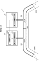
- FIG. 1 is an overall schematic diagram of the equipment required for automatic travel of a lawn mower according to one embodiment of the present invention.
- 1 is a side external view of a lawn mower according to one embodiment to which the present invention is applied;
- FIG. 1 is a top conceptual view of the main parts of a lawn mower according to one embodiment of the present invention;
- FIG. It is a figure which shows the relationship of the positional relationship of the deviation
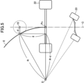
- FIG. 4 is a diagram showing geometric relationships when automatically traveling on an electromagnetic induction line;
- FIG. 5 is a diagram showing the relationship between the trajectory of a pivot and the trajectory of a center guide line detection sensor;
- FIG. 5 is a diagram showing the relationship between the trajectory of a pivot and the trajectory of a center guide line detection sensor;
- FIG. 5 is a diagram showing the relationship between the trajectory of a pivot and the trajectory of a center guide line detection sensor;
- FIG. 5 is a diagram showing the relationship between the trajectory of a pivot and the trajectory of a center guide line detection sensor;
- 4 is a flowchart of an example steering control process according to one embodiment of the present invention; It is a figure which shows an example of a driving route. It is a figure showing the whole automatic travel system composition concerning one embodiment of the present invention.
- FIG. 3 is a diagram showing an example of an alternating current supplied to an electromagnetic induction wire and a synchronization signal;
- FIG. 4 is a comparison diagram of electric field strengths when alternating currents of adjacent closed-loop electromagnetic induction wires are in phase and when they are out of phase;
- FIG. 1 is an overall schematic diagram of devices required for automatic traveling of a lawnmower according to one embodiment of the present invention.
- a lawnmower 1 that performs lawn mowing work on a golf course while measuring the current position using the RTK-GPS system (Real Time Kinematic GPS: interferometric positioning system) is shown.
- RTK-GPS system Real Time Kinematic GPS: interferometric positioning system
- the base station 3 includes a GPS receiving device 31 and a transmitting/receiving device 32 corresponding to an RTK-GPS reference station, a GPS antenna 35, and a communication antenna 36.
- the base station 3 is installed at a point whose longitude, latitude and height are known.
- the GPS receiver 31 generates correction information for correcting the positional information error of the lawn mower 1 .
- This correction information is appropriately transmitted to the lawn mower 1 through the transmitting/receiving device 32 and the communication antenna 36 .
- the transmission timing of the correction information may be, for example, the timing requested by the lawnmower 1 or at predetermined intervals (for example, every 100 ms).
- the RTK-GPS system is used as the positioning system, but a differential GPS system (Differential GPS: relative positioning system) may also be used.
- a differential GPS system Different GPS: relative positioning system
- the lawn mower 1 includes a machine body 10, a control device 11, a vehicle speed sensor 12, an azimuth angular velocity sensor 13, a left guide wire detection sensor 14, a center guide wire detection sensor 15, a right guide wire detection sensor 16, a drive controller 17, and a GPS antenna. 18, a communication antenna 19, a cutting blade (front) 20, a cutting blade (rear) 21, a drive wheel 22, a steering wheel 23, an operation input section 24, a display section 25, and an audio output section .
- the control device 11 comprises a computer device having a CPU, communication function, storage function (drive unit and/or input/output interface for internal recording medium and external recording medium), display function (display), and a predetermined computer program.
- This computer program causes the computer device to be controlled by a GPS receiver 101, a transmitter/receiver 102, a vehicle information receiver 105, a drive commander 106, a control information generator 107, a storage 108, a removable recording medium interface 109, and a main controller 112. , to function as The main control unit 112 comprehensively controls the operation of each unit.
- This computer device has an RTC (Real Time Clock) module that outputs time data and a synchronous clock for control operations.
- the control device 11 may be provided with an azimuth angular velocity sensor for cases such as when the lawn mower is not provided with an azimuth angular velocity sensor. Details of the control device 11 will be described later.
- the vehicle speed sensor 12 detects the running speed of the lawn mower 1 when moving forward or backward.
- the azimuth angular velocity sensor 13 detects the behavior (dynamics) of the lawn mower 1 such as tilting, turning, and wobbling from angular velocities about three-dimensional axes (roll, pitch, yaw).
- the data to be measured by the azimuth angular velocity sensor 13 may be substituted by an accelerometer.
- the sensors 11 and 12 can also be substituted by taking in the measurement result of various instruments with which the lawn mower 1 is equipped.
- the three lead wire detection sensors, the center lead wire detection sensor 15, the left lead wire detection sensor 14, and the right lead wire detection sensor 16, detect the alternating current supplied to the electromagnetic lead wire when automatically traveling along the travel route on the electromagnetic lead wire. It detects the strength of the alternating magnetic field generated by the current.
- the drive control unit 17 controls a work drive mechanism that drives the mowing blades of the lawn mower 1 to move up and down, actuation, etc. based on a work control signal described later, and controls the lawn mower 1 based on a travel control signal described later. It controls the traveling drive mechanism that drives the turning to the right and left, forward movement, backward movement, etc.
- the drive control unit 17 may be provided separately from the control device 11 as illustrated, or may be implemented as one function of the control device 11 .
- the GPS antenna 18 functions as a position detection sensor that receives GPS data transmitted from GPS satellites.
- Communication antenna 19 enables communication with communication antenna 36 of base station 3 . This communication is used for sending and receiving correction information for correcting errors in the positional information of the lawn mower 1, communication with the operator of the lawn mower 1, signals for remote control of the lawn mower 1, and the like. be.
- the operation input unit 24 is composed of a keyboard, a mouse, etc., but is not limited to these.
- the display unit 25 is composed of a CRT, a liquid crystal display, a laminated display lamp, etc., but is not limited to these.
- the audio output unit 26 is composed of a speaker or the like, but is not limited to this.
- FIG. 2 is an external view of the lawn mower 1 viewed from the side.
- FIG. 3 is a top conceptual view of the main parts of a lawn mower according to one embodiment of the present invention.
- the control device 11 , the vehicle speed sensor 12 , the azimuth angular velocity sensor 13 , the drive control section 17 , the travel drive mechanism and the work drive mechanism described above are incorporated in the machine body 10 of the lawn mower 1 .
- the azimuth angular velocity sensor 13 is installed at a position where the behavior of the lawn mower 1 is correctly transmitted.
- the GPS antenna 18 is provided substantially at the center of the body of the lawn mower 1, that is, substantially at the center of the body in the longitudinal and width directions.
- the communication antenna 19 is attached so as to protrude from the rear surface of the body of the lawn mower 1 so as not to interfere with the reception of the GPS antenna 18 .
- the three guide wire detection sensors, the center guide wire detection sensor 15, the left guide wire detection sensor 14, and the right guide wire detection sensor 16, are attached to the stay 27 attached to the cutting blade (front) 20.
- the center guide line detection sensor 15 is located on the center line C of the lawn mower 1 and is separated from the pivot Pv located at the center of the axle of the drive wheel 22 that is the turning center of the lawn mower 1 by a distance l [m], which will be described later.
- the left guide wire detection sensor 14 and the right guide wire detection sensor 16 are arranged on a straight line perpendicular to the center line C of the lawn mower 1 and passing through the center guide wire detection sensor 15. on the left and right sides of the center guide wire detection sensor 15 at a distance D [m] described later.
- the lawn mower 1 includes a pair of cutting blades (front) 20 and cutting blades (rear) 21 for mowing grass.
- the front cutting blade 18 cuts grass on the left and right edges of the cutting width W [m] in the direction perpendicular to the traveling direction.
- the rear cutting blade 19 cuts the grass in the center of the cutting width W [m].
- This mowing width W [m] is the working width in which the lawn mower 1 can mow the grass in one run.
- GPS receiver 101 of control device 11 outputs GPS data received by GPS antenna 18 to control information generator 107 .
- Transmitting/receiving unit 102 enables communication between control information generating unit 107 and base station 3 via communication antenna 19, and is used to correct errors in the positional information of lawn mower 1 received by communication antenna 19.
- the correction information is output to control information generating section 107 .
- the control information generator 107 calculates the current position of the lawn mower 1 based on the GPS data received by the GPS antenna 18 and correction information for correcting errors in the position information of the lawn mower 1 received by the communication antenna 19 . Generate location information to represent.
- the transmission/reception unit 102 can be connected to any network regardless of whether it is wired or wireless, a LAN (Local Area Network), or a public communication line.
- the vehicle information receiving unit 105 acquires detection information representing the running speed, direction, and behavior of the lawn mower 1 from the vehicle speed sensor 12 and the azimuth angular velocity sensor 13, and/or position tracking by GPS data. If the acquired information is analog data, it is converted into digital data and output. At that time, if necessary, data correction is performed by removing offset components and drift components from the output of the azimuth angular velocity sensor 13 . In addition, the vehicle information receiving unit 105 acquires magnetic field intensities from the center guide wire detection sensor 15 , the left guide wire detection sensor 14 , and the right guide wire detection sensor 16 . The output information of vehicle information receiving section 105 is recorded in storage section 108 in association with the current time data.
- the drive command unit 106 determines the control contents of the travel drive mechanism or the work drive mechanism to control the travel or work of the lawn mower 1. to the drive control unit 17. Based on this information, the drive control unit 17 controls the traveling drive mechanism or work drive mechanism of the lawn mower. As a result, the lawnmower 1 can automatically travel and automatically travel to mowing the lawn.
- the storage unit 108 can record travel route and operation data, predetermined computer programs, and the like.
- the storage unit 108 is composed of an arbitrary number of storage components such as hard disks and semiconductor memories, but is not limited to these.
- a removable recording medium 40 such as an optical disc such as a CD-ROM or DVD, a USB memory, or an SD memory card can be detachably attached to the removable recording medium interface unit 109 .
- the removable recording medium interface unit 109 can read data recorded on the mounted removable recording medium 40 and write data to the removable recording medium 40 .
- the removable recording medium interface unit 109 is, for example, a dedicated reader/writer or the like if the removable recording medium 40 is an optical disc such as a CD-ROM or DVD, a USB port or the like if the removable recording medium 40 is a USB memory, or an SD memory card.
- it may be a card slot or the like, but it is not limited to these.
- the traveling route and operation data are recorded in the storage unit 108 or the removable recording medium 40 attached to the removable recording medium interface unit 109 .
- the operation data is associated with the traveling route, and the lawn mowing work including the up-and-down operation of the cutting blade (front) 20 and the cutting blade (rear) 21 while the lawn mower 1 is traveling or stopped, and starting or stopping the rotation. , including the speed of the lawnmower 1 and the automatic running mode.
- the automatic travel mode includes a positioning mode in which the vehicle automatically travels based on a received positioning signal, and an electromagnetic induction mode in which a magnetic field generated from an electromagnetic induction wire is detected and the vehicle automatically travels along the electromagnetic induction wire.
- the control information generating unit 107 controls the center guide line detection sensor 15, Based on the deviation of the lawn mower 1 from the electromagnetic induction wire E calculated from the magnetic field intensity obtained by the left induction wire detection sensor 14 and the right induction wire detection sensor 16, a travel control signal and a work control signal are generated and output. . This makes it possible to work by automatic driving.
- FIG. 4 is a diagram showing the relationship between the displacement of the induction wire detection sensor from the electromagnetic induction wire and the positional relationship between the electromagnetic induction wire and the induction wire detection sensor.
- FIG. 5 is a diagram showing the geometrical relationship when automatically traveling on electromagnetic induction lines.
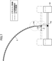
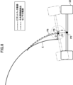
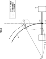
- 6 to 9 are diagrams showing the relationship between the trajectory of the pivot and the trajectory of the center guide line detection sensor.
- FIG. 10 is a flowchart of an example steering control process according to one embodiment of the present invention.
- the steering control system 60 includes the control device 11 , the center guide wire detection sensor 15 , the left guide wire detection sensor 14 and the right guide wire detection sensor 16 .
- FIG. 4 is a diagram showing the relationship between the deviation of the induction wire detection sensor from the electromagnetic induction wire and the positional relationship between the electromagnetic induction wire and the induction wire detection sensor in a cross section perpendicular to the traveling direction of the lawn mower 1 .
- the vertical height from the electromagnetic induction wire E to the central induction wire detection sensor 15 is h [m]
- the horizontal displacement of the central induction wire detection sensor 15 from the electromagnetic induction wire E is Let d [m] be the horizontal distance from the electromagnetic induction wire E to the central induction wire detection sensor 15, and ⁇ be the angle between the central induction wire detection sensor 15 and a vertical straight line passing through the electromagnetic induction wire.
- the value of the horizontal distance d to the detection sensor 15 is proportional to the distance r [m] from the electromagnetic induction wire E to the central induction wire detection sensor 15 .
- the strength of the magnetic field emitted from the electromagnetic induction wire E is inversely proportional to the distance r [m] from the electromagnetic induction wire E to the central induction wire detection sensor 15, the larger the r [m], the more the central induction wire detection sensor The magnetic field detected by 15 becomes weaker.
- the maximum value of r[m] that can be detected by the central guiding wire detection sensor 15 Since the value of d[m] is proportional to the value of r[m], the maximum value of d[m] that can be detected by the central guide wire detection sensor 15 can also be determined.
- This maximum detectable horizontal distance d[m] is called the maximum detectable distance D[m].
- the detection performance of the left guide wire detection sensor 14 and the right guide wire detection sensor 16 is the same, and the maximum detection distance is also D [m].
- the center guide wire detection sensor 15 is arranged on the center line C of the lawn mower 1 at a distance l [m] from the pivot Pv, and the left guide wire detection sensor 14 and the right guide wire detection sensor 14 are arranged at a distance l [m] from the pivot Pv.
- the sensors 16 are arranged on a straight line perpendicular to the center line C of the lawn mower 1 and passing through the central guiding wire detection sensor 15, on the left and right sides of the central guiding wire detecting sensor 15, and at the maximum detection distance D from the central guiding wire detecting sensor 15. are arranged at positions separated by [m]. Since the central guiding wire detection sensor 15, the left guiding wire detecting sensor 14, and the right guiding wire detecting sensor 16 have the same detection performance, with such arrangement, from the electromagnetic guiding wire E at the position of the central guiding wire detecting sensor 15 deviation can be detected.
- the control information generation unit 107 of the control device 11 is detection data acquired by the center guide line detection sensor 15, the left guide line detection sensor 14, and the right guide line detection sensor 16, which are acquired by the vehicle information reception unit 105.
- the deviation of the lawn mower 1 from the electromagnetic induction line E is calculated based on the magnetic field intensity. Specifically, when the central guiding wire detection sensor 15 does not detect a magnetic field and the left guiding wire detecting sensor 14 detects a magnetic field, the electromagnetic guiding wire E is positioned to the left of the left guiding wire detecting sensor 14. It can be determined that there is deviation.
- the electromagnetic guiding wire E is shifted to the right side of the right guiding wire detecting sensor 16. can be determined. Then, when the central induction wire detection sensor 15 detects a magnetic field and the left induction wire detection sensor 14 detects a magnetic field, the electromagnetic induction wire E is positioned between the central induction wire detection sensor 15 and the left induction wire detection sensor 14.
- the control information generation unit 107 when the lawn mower 1 (more precisely, the position of the central guide wire detection sensor 15) is displaced from the electromagnetic induction wire E, the allowable deviation width for stopping the lawn mower 1 is set.
- the control information generation unit 107 When the maximum detection distance D [m] is set and the central guide wire detection sensor 15 does not detect the magnetic field, the control information generation unit 107 generates a travel control signal for stopping the lawn mower 1, and mowing the lawn. Stop machine 1.
- the calculation of the deviation of the lawn mower 1 from the electromagnetic induction line E is not limited to the configuration calculated by the control information generation unit 107.
- the calculated deviation is calculated outside the control device 11. may be any other suitable configuration, such as a configuration in which the controller receives the .
- the central induction wire detection sensor 15 may not be arranged.
- the pivot (control point) Pv of the lawn mower 1 is set so that the point (turning center O) at which the normal lines of the steered wheels intersect is the radius R. Move along the arc trajectory.
- the central guide wire detection sensor 15 which will be considered below, is located within the range of the position of the lawn mower 1 in the longitudinal direction. is omitted in FIG.
- the control information generation unit 107 calculates the magnetic field intensity obtained by the central guide wire detection sensor 15, the left guide wire detection sensor 14, and the right guide wire detection sensor 16, and the electromagnetic induction wire E of the lawn mower 1
- a travel control signal is generated and output based on the deviation of the .
- the control information generation unit 107 generates a turf calculated from the magnetic field strength acquired by the central guide wire detection sensor 15, the left guide wire detection sensor 14, and the right guide wire detection sensor 16 for each control cycle t [seconds].
- a travel control signal is generated and output to turn the mower 1 or to move the mower 1 straight so as to cancel the deviation.
- the output travel control signal is sent to the drive control unit 17 via the drive command unit 106, and the drive control unit 17 controls the drive wheels 22 and turns the steered wheels 23 according to the received travel control signal.
- the lawn mower 1 does not move backward when traveling on the electromagnetic induction wire.
- the traveling route must not include a curve with a radius of curvature smaller than the minimum turning radius.
- the lawn mower 1 can travel on a curve with a minimum turning radius or more. Therefore, the limit of whether or not the lawnmower 1 can automatically travel without deviating from the electromagnetic induction line can be considered as an arc having a radius equal to the minimum turning radius.
- the control information generator 107 does not detect deviation, so the steering control system 60 does not steer and the lawn mower 1 runs straight. .
- the speed at which the lawn mower 1 travels on the electromagnetic induction wire E is v [m/sec]
- the pivot Pv and the central induction wire detection sensor 15 are at the initial position It will be the position P1 which is straight ahead from P0 by tv [m].
- the control information generator 107 detects a deviation from the electromagnetic induction line E, so the steering control system 60 causes the lawn mower 1 to approach the electromagnetic induction line with a minimum turn. In other words, steer to turn to the left with the minimum turning radius.
- the pivot Pv is at the position P1 at this time, as can be seen from FIG. It is not possible to return to the electromagnetic induction line E. That is, the lawn mower 1 cannot return to the electromagnetic induction wire E because the turning timing is too late.
- the central guiding wire detection sensor 15 detects that the position of the central guiding wire detection sensor 15 is deviated to the right from the electromagnetic induction wire E, so the steering control system 60 starts mowing the lawn.
- the aircraft 1 is steered so as to approach the electromagnetic guidance line with a minimum turn, that is, turn to the left with a minimum turning radius.
- the pivot Pv is at the position P3, so that the lawn mower 1 turns with the minimum turn, so that the lawn mower 1 moves on the electromagnetic induction line E without deviating from the electromagnetic induction line E, as can be seen from FIG. can run.
- the lawn mower 1 cannot return to the electromagnetic induction wire E when the center induction wire detection sensor 15 is away from the pivot Pv by a distance smaller than tv [m]. can be understood by comparing
- the central guiding line detection sensor 15 in the initial position, the central guiding line detection sensor 15 is positioned to the right in the direction perpendicular to the center line C of the lawn mower 1.
- P5 be the initial position of the pivot Pv
- P6 be the initial position of the center guide line detection sensor 15 .
- the central guiding line detection sensor 15 detects that the position of the central guiding line detection sensor 15 is deviated to the right from the electromagnetic guidance line E, so the steering control system 60 causes the lawn mower 1 to move to the minimum position.
- steer to approach the electromagnetic induction line that is, to turn to the left with the minimum turning radius.
- the position of the pivot Pv is a position P7 advanced by a distance tv [m] on the circumference of the minimum turning radius R, and the position of the center guide line detection sensor 15 is from the position P7. , to a position P8 that is tv [m] away in the tangential direction of the circumference of the minimum turning radius R at the position P7.
- the position of the central guiding wire detection sensor 15 is still deviated to the right from the electromagnetic guiding wire E.
- the steering control system 60 steers the mower 1 again to approach the electromagnetic guideline with a minimum turn, ie turn to the left with a minimum turn radius.
- the lawn mower 1 can return to the electromagnetic induction wire E by repeating such steering for each control cycle.
- the center guide line detection sensor 15 is located on the center line C of the lawn mower 1 at a distance tv [m] away from the pivot Pv.
- the center guide line detection sensor 15 is positioned on the center line C of the lawn mower 1 at a distance from the pivot Pv. , and in the initial position, the center guide line detection sensor 15 is located at a distance of the permissible deviation width D [m] to the right in the direction perpendicular to the center line C of the lawn mower 1.
- P9 be the initial position of the pivot Pv
- P10 be the initial position of the central guiding wire detection sensor 15 .
- the control information generation unit 107 detects that the position of the central guide line detection sensor 15 is shifted to the right from the electromagnetic guide line E, so the steering control system 60 causes the lawn mower 1 to move to the minimum turning position. steer to approach the electromagnetic induction line, that is, to turn to the left with the minimum turning radius. Therefore, the lawn mower 1 runs on the electromagnetic induction line E with the minimum turning radius.
- the trajectory of the central guide line detection sensor 15 becomes parallel to the electromagnetic guide line E of the minimum turning radius R, that is, it cannot approach the electromagnetic guide line E, but it does not move away from it. Therefore, even if the vehicle is steered to turn to the left with the minimum turning radius in each control cycle, the trajectory of the central guidance line detection sensor 15 remains parallel to the electromagnetic guidance line E with the minimum turning radius R.
- the central guidance line detection sensor 15 is placed farthest from the pivot Pv.
- the position of the guide wire detection sensor 15 is such that the center guide wire detection sensor 15 is on the center line C of the lawn mower 1 and is at a distance from the pivot Pv. It can be seen that the positions are separated by
- l [m] is greater than or equal to tv [m]
- three lead wire detection sensors, the center lead wire detection sensor 15, the left lead wire detection sensor 14, and the right lead wire detection sensor 16 detect the electromagnetic lead wire E at the position of the center lead wire detection sensor 15. deviation was detected. That is, the detection reference point for deviation from the electromagnetic induction wire E detected by the three induction wire detection sensors of the central induction wire detection sensor 15, the left induction wire detection sensor 14, and the right induction wire detection sensor 16 is the central induction wire It was the position of the detection sensor 15 .
- the detection reference point for the deviation from the electromagnetic induction wire E detected by the plurality of induction wire detection sensors is the above condition (tv [m] that's all, below), the deviation detection reference point deviates from the electromagnetic induction line by more than the allowable width D [m] It is also understood that automatic driving is possible without
- the vehicle information receiving unit 105 acquires the magnetic field intensity, which is the detection data acquired by each lead wire detection sensor, from the center guide wire detection sensor 15, the left guide wire detection sensor 14, and the right guide wire detection sensor 16 (S1 ).
- the control information generation unit 107 generates an electromagnetic field of the lawn mower 1 calculated from the magnetic field intensities obtained by the central guide wire detection sensor 15, the left guide wire detection sensor 14, and the right guide wire detection sensor 16 for each control cycle t [seconds]. Based on the deviation from the guide line E, a travel control signal is generated and output to turn the lawn mower 1 so as to cancel the deviation or to make the lawn mower 1 go straight (S2). The output travel control signal is sent to the drive control unit 17 via the drive command unit 106, and the drive control unit 17 controls the drive wheels 22 according to the received travel control signal to turn the steered wheels 23 ( S3).
- the configuration of the induction wire detection sensor is the electromagnetic induction wire E detected by three induction wire detection sensors: the central induction wire detection sensor 15, the left induction wire detection sensor 14, and the right induction wire detection sensor 16.
- the reference point for detecting the deviation from the center guide line detection sensor 15 is the position of the center guide line detection sensor 15, the front wheels are the driving wheels, the rear wheels are the steering wheels, and the pivot Pv is located at the center of the axle of the driving wheels.
- the detection reference point of the deviation from the electromagnetic induction line E detected by the plurality of induction line detection sensors is tv [m] or more, and Any appropriate configuration of the guide wire detection sensor and the vehicle can be used as long as the guide wire detection sensor is arranged at a position forward of the pivot Pv by a horizontal distance l [m] that satisfies the following.
- the permissible deviation width is set as the maximum detection distance of the central guiding line detection sensor, but the permissible deviation width does not have to be the maximum detection distance of the central guiding line detection sensor, and may be any appropriate width. be able to.
- Some functions of the steering control system may be configured separately from the cruise control device, such as a separate server, base station, tablet computer, or the like.
- FIG. 11 is a diagram showing an example of a travel route.
- FIG. 12 is a diagram showing the overall configuration of an automatic driving system according to one embodiment of the present invention.
- FIG. 13 is a diagram showing an example of an alternating current supplied to an electromagnetic induction wire and a synchronization signal.
- FIG. 14 is a comparison diagram of the electric field intensity when the alternating currents of the adjacent closed-loop electromagnetic induction wires are in phase and when they are out of phase.
- FIG. 11 is a diagram showing an example of a travel route, in which the driver enters the hall H from the cart path CP, mows the lawn in the hall H, returns to the cart path CP again from the hall H, proceeds along the cart path CP, and travels along the cart path CP.
- FIG. 12 is a diagram showing the overall configuration of the automatic driving system according to one embodiment of the present invention, which is an enlarged view from the vicinity of the switching point SWP1 to the vicinity of the switching point SWP2.
- the automatic driving system 5 includes a first power supply device corresponding to the first closed-loop electromagnetic induction wire CL1, the second closed-loop electromagnetic induction wire CL2, the first closed-loop electromagnetic induction wire CL1, and the second closed-loop electromagnetic induction wire CL2. 51 , including a second power supply 52 .
- the first closed-loop electromagnetic induction line CL1 and the second closed-loop electromagnetic induction line CL2 are arranged adjacent to each other.
- a first power supply 51 and a second power supply 52 are connected to the first closed-loop electromagnetic induction line CL1 and the second closed-loop electromagnetic induction line CL2, respectively.
- the first power supply device 51 includes a first alternating current generator 511 and a synchronization signal generator 513 .
- the second power supply device 52 also includes a second alternating current generator 521 .
- the first AC current generator 511 and the second AC current generator 521 generate low-frequency AC currents of the same frequency.
- a square wave alternating current of 1.5 kHz is generated as shown in FIG. can be any other suitable shape of alternating current.
- the synchronization signal generator 513 generates a synchronization signal at a predetermined timing.
- the synchronization signal generated by the synchronization signal generator 513 is supplied to the second alternating current generator 521, and the second alternating current generator 521 generates the first signal at a predetermined timing based on the synchronization signal.
- a rectangular wave alternating current is generated in synchronization with the rectangular wave alternating current generated by the alternating current generator 511 . In this manner, the rectangular wave alternating current generated by the first alternating current generator 511 and the rectangular wave alternating current generated by the second alternating current generator 521 are synchronized at a predetermined timing.
- the travel route TP from the switching point SWP1 to the switching point SWP2 is on the electromagnetic induction line.
- the first portion CL1P of the first closed-loop electromagnetic induction wire CL1 and the first portion CL2P of the second closed-loop electromagnetic induction wire CL2 are arranged adjacent to each other so as to form the traveling path TP. It is At both ends of the first portion CL1P of the first closed-loop electromagnetic induction wire CL1 and both ends of the first portion CL2P of the second closed-loop electromagnetic induction wire CL2, the first closed-loop electromagnetic induction wire CL1 and the second closed-loop electromagnetic induction
- the line CL2 is bent at right angles, and the bent portion forms a straight line on the cart path CP.
- the first closed-loop electromagnetic induction wire CL1 and the second closed-loop electromagnetic induction wire CL2 can be closely adjacent to each other, and the interval between the electromagnetic induction wires on the travel route TP can be reduced. Also, the lawn mower 1 can be prevented from being guided in the bent direction of the first closed-loop electromagnetic induction line CL1 or the second closed-loop electromagnetic induction line CL2, instead of the direction of the travel path TP.
- the alternating current generated by the first alternating current generator 511 and the second closed-loop electromagnetic induction line CL2 are shifted, the alternating magnetic fields generated from the alternating currents in the vicinity of adjacent portions partially cancel each other, as shown in the diagram on the right side of FIG. , the strength of the magnetic field decreases, and the induction wire detection sensors become unable to detect the magnetic field, making it difficult to continue running.
- the magnetic field strength near the adjacent portion is reduced to It is possible to suppress the decrease (see the diagram on the left side of FIG. 14) and continue running.
- the number of adjacent closed-loop electromagnetic induction wires forming the travel route TP is limited to two. instead, it can be any other suitable number.
- the switching points SWP1 and SWP2 are set at positions where positioning signals from GPS satellites can be received satisfactorily.
- the automatic traveling mode is switched from the positioning mode to the electromagnetic induction mode, and automatic traveling is performed by electromagnetic induction.
- the switching point SWP2 is reached, the automatic traveling mode is switched from the electromagnetic induction mode to the positioning mode, and automatic traveling is performed by positioning (GPS) to head for the garage W.
- the switching of the automatic driving mode is performed by a driving control signal generated by the control information generation unit 107 based on the driving route and operation data recorded in the storage unit 108 or the removable recording medium 40 attached to the removable recording medium interface unit 109. done.
- the electromagnetic induction wire can be used over a long distance. Automatic driving becomes possible.
- a recording medium recording a computer program that implements the method of the above embodiment may be supplied to the control device 10 .
- the object of the present invention can be achieved by the computer of the control device 10 reading and executing the computer program recorded on the recording medium. Therefore, since the computer program itself read from the recording medium implements the method of the present invention, the computer program constitutes the present invention.
- the present invention is also applicable to sprinklers, spreaders, fertilizers, seeders, soil condition measuring machines, harvesters, cultivators, and cultivated soil. It is applicable to any other suitable vehicle such as machines, agricultural machines including soil tillers, cleaning machines, carts and the like.
- the positioning signal used in the positioning mode is GPS data, but the positioning signal used in the positioning mode is not limited to this. Any other appropriate positioning signals such as beacon signals, BLE beacon signals, impulse UWB (IR-UWB) signals, IMES (Indoor Messaging System) signals, or a combination of all or part of them, transmitted from access points can do.
- Any other appropriate positioning signals such as beacon signals, BLE beacon signals, impulse UWB (IR-UWB) signals, IMES (Indoor Messaging System) signals, or a combination of all or part of them, transmitted from access points can do.
- Reference Signs List 1 Lawn mower 10 Main body 11 Control device 12 Vehicle speed sensor 13 Azimuth angular velocity sensor 14 Left guide wire detection sensor 15 Central guide wire detection sensor 16 ... right guide wire detection sensor 17 ... drive control unit 18 ... GPS antenna 19 ... communication antenna 20 ... cutting blade (front) 21 Cutting blade (rear) 22... Driving wheel 23... Steering wheel 24... Operation input unit 25... Display unit 26... Audio output unit 27... Stay 101... GPS receiving unit 102... Transmitting/receiving unit 105... Vehicle information receiving unit 106... Driving command unit 107... Control information generating unit 108... Storage unit 109... Removable recording medium interface unit 112... Main control unit 3...
Landscapes
- Engineering & Computer Science (AREA)
- Aviation & Aerospace Engineering (AREA)
- Radar, Positioning & Navigation (AREA)
- Remote Sensing (AREA)
- Physics & Mathematics (AREA)
- General Physics & Mathematics (AREA)
- Automation & Control Theory (AREA)
- Life Sciences & Earth Sciences (AREA)
- Environmental Sciences (AREA)
- Control Of Position, Course, Altitude, Or Attitude Of Moving Bodies (AREA)
- Guiding Agricultural Machines (AREA)
Priority Applications (4)
| Application Number | Priority Date | Filing Date | Title |
|---|---|---|---|
| US18/705,283 US20250390101A1 (en) | 2021-10-28 | 2021-10-28 | Vehicle, System for Steering Control, Method, Program, Recording Medium Storing Program, and Autonomous Travelling System |
| PCT/JP2021/039882 WO2023073882A1 (ja) | 2021-10-28 | 2021-10-28 | 車両、操舵制御のためのシステム、方法、プログラム、プログラムを記録した記録媒体、自動走行システム |
| JP2023555994A JP7470878B2 (ja) | 2021-10-28 | 2021-10-28 | 車両、操舵制御のためのシステム、方法、プログラム、プログラムを記録した記録媒体、自動走行システム |
| US18/889,253 US20250123629A1 (en) | 2021-10-28 | 2024-09-18 | Vehicle, System for Steering Control, Method, Program, Recording Medium Storing Program, and Autonomous Travelling System |
Applications Claiming Priority (1)
| Application Number | Priority Date | Filing Date | Title |
|---|---|---|---|
| PCT/JP2021/039882 WO2023073882A1 (ja) | 2021-10-28 | 2021-10-28 | 車両、操舵制御のためのシステム、方法、プログラム、プログラムを記録した記録媒体、自動走行システム |
Related Child Applications (2)
| Application Number | Title | Priority Date | Filing Date |
|---|---|---|---|
| US18/705,283 A-371-Of-International US20250390101A1 (en) | 2021-10-28 | 2021-10-28 | Vehicle, System for Steering Control, Method, Program, Recording Medium Storing Program, and Autonomous Travelling System |
| US18/889,253 Continuation US20250123629A1 (en) | 2021-10-28 | 2024-09-18 | Vehicle, System for Steering Control, Method, Program, Recording Medium Storing Program, and Autonomous Travelling System |
Publications (1)
| Publication Number | Publication Date |
|---|---|
| WO2023073882A1 true WO2023073882A1 (ja) | 2023-05-04 |
Family
ID=86157515
Family Applications (1)
| Application Number | Title | Priority Date | Filing Date |
|---|---|---|---|
| PCT/JP2021/039882 Ceased WO2023073882A1 (ja) | 2021-10-28 | 2021-10-28 | 車両、操舵制御のためのシステム、方法、プログラム、プログラムを記録した記録媒体、自動走行システム |
Country Status (3)
| Country | Link |
|---|---|
| US (2) | US20250390101A1 (https=) |
| JP (1) | JP7470878B2 (https=) |
| WO (1) | WO2023073882A1 (https=) |
Families Citing this family (1)
| Publication number | Priority date | Publication date | Assignee | Title |
|---|---|---|---|---|
| KR20240024916A (ko) * | 2021-06-25 | 2024-02-26 | 아이치 세이코우 가부시키가이샤 | 차량용 시스템 |
Citations (5)
| Publication number | Priority date | Publication date | Assignee | Title |
|---|---|---|---|---|
| JPS62175813A (ja) * | 1986-01-30 | 1987-08-01 | Komatsu Ltd | 無人車輌の曲線経路誘導方法 |
| JPH03192406A (ja) * | 1989-12-22 | 1991-08-22 | Nec Corp | 搬送車の走行制御方法 |
| JPH05345056A (ja) * | 1992-06-17 | 1993-12-27 | Kubota Corp | ゴルフカート |
| JP2004086767A (ja) * | 2002-08-28 | 2004-03-18 | Nippon Yusoki Co Ltd | 無人搬送システム、及び無人搬送方法 |
| JP2020140424A (ja) * | 2019-02-28 | 2020-09-03 | 日本車輌製造株式会社 | 搬送車および搬送車の操舵制御プログラム |
-
2021
- 2021-10-28 WO PCT/JP2021/039882 patent/WO2023073882A1/ja not_active Ceased
- 2021-10-28 US US18/705,283 patent/US20250390101A1/en active Pending
- 2021-10-28 JP JP2023555994A patent/JP7470878B2/ja active Active
-
2024
- 2024-09-18 US US18/889,253 patent/US20250123629A1/en active Pending
Patent Citations (5)
| Publication number | Priority date | Publication date | Assignee | Title |
|---|---|---|---|---|
| JPS62175813A (ja) * | 1986-01-30 | 1987-08-01 | Komatsu Ltd | 無人車輌の曲線経路誘導方法 |
| JPH03192406A (ja) * | 1989-12-22 | 1991-08-22 | Nec Corp | 搬送車の走行制御方法 |
| JPH05345056A (ja) * | 1992-06-17 | 1993-12-27 | Kubota Corp | ゴルフカート |
| JP2004086767A (ja) * | 2002-08-28 | 2004-03-18 | Nippon Yusoki Co Ltd | 無人搬送システム、及び無人搬送方法 |
| JP2020140424A (ja) * | 2019-02-28 | 2020-09-03 | 日本車輌製造株式会社 | 搬送車および搬送車の操舵制御プログラム |
Also Published As
| Publication number | Publication date |
|---|---|
| US20250390101A1 (en) | 2025-12-25 |
| JPWO2023073882A1 (https=) | 2023-05-04 |
| JP7470878B2 (ja) | 2024-04-18 |
| US20250123629A1 (en) | 2025-04-17 |
Similar Documents
| Publication | Publication Date | Title |
|---|---|---|
| EP3403155B1 (en) | Self-propellered robotic tool navigation | |
| US11696525B2 (en) | Automatic travel work machine, automatic travel grass mower, grass mower, and grass mower automatic travel system | |
| CN103543746B (zh) | 用于自动割草机的导航系统和方法 | |
| US10031525B2 (en) | Swath tracking system for an off-road vehicle | |
| US20210165421A1 (en) | Moving robot and controlling method thereof | |
| JP5712097B2 (ja) | 自律走行作業車の制御装置 | |
| CN105700533A (zh) | 基于北斗导航的农业机械自动驾驶控制系统及方法 | |
| EP2306423B1 (en) | Train-of-vehicle travel support device | |
| US6732024B2 (en) | Method and apparatus for vehicle control, navigation and positioning | |
| US20200340819A1 (en) | Vehicle manual guidance systems with steering wheel angle sensors and road wheel angle sensors | |
| JP2013228821A (ja) | 作業機械及びその構成装置、コンピュータプログラム | |
| JP2024109577A (ja) | トラクタ | |
| WO2020062039A1 (en) | A docking station for use with an autonomous tool, an autonomous lawn mower and a method of guiding an autonomous tool towards a docking station | |
| JP2022551991A (ja) | 車両およびトレーラーに関する振動検出 | |
| US20250123629A1 (en) | Vehicle, System for Steering Control, Method, Program, Recording Medium Storing Program, and Autonomous Travelling System | |
| CN111090284B (zh) | 自行走设备返回基站的方法及自行走设备 | |
| CN110933317B (zh) | 一种车载摄像头智能转向方法和系统 | |
| JP3429151B2 (ja) | 作業車の走行制御装置 | |
| US12369522B2 (en) | Work machine system and work machine | |
| US12510891B2 (en) | Travel route control of autonomous work vehicle to reduce travel distance | |
| JPS633315A (ja) | 自立走行する車両の走行制御方法 | |
| JP6342764B2 (ja) | 自動走行車両 | |
| JP2889257B2 (ja) | 移動体の位置検知装置 | |
| JPH09305229A (ja) | 移動体自動運転装置 | |
| JP6456083B2 (ja) | 自動走行車両 |
Legal Events
| Date | Code | Title | Description |
|---|---|---|---|
| 121 | Ep: the epo has been informed by wipo that ep was designated in this application |
Ref document number: 21962428 Country of ref document: EP Kind code of ref document: A1 |
|
| WWE | Wipo information: entry into national phase |
Ref document number: 2023555994 Country of ref document: JP |
|
| NENP | Non-entry into the national phase |
Ref country code: DE |
|
| 122 | Ep: pct application non-entry in european phase |
Ref document number: 21962428 Country of ref document: EP Kind code of ref document: A1 |