WO2023073882A1 - Vehicle, system for steering control, method, program, recording medium storing program, and autonomous travelling system - Google Patents
Vehicle, system for steering control, method, program, recording medium storing program, and autonomous travelling system Download PDFInfo
- Publication number
- WO2023073882A1 WO2023073882A1 PCT/JP2021/039882 JP2021039882W WO2023073882A1 WO 2023073882 A1 WO2023073882 A1 WO 2023073882A1 JP 2021039882 W JP2021039882 W JP 2021039882W WO 2023073882 A1 WO2023073882 A1 WO 2023073882A1
- Authority
- WO
- WIPO (PCT)
- Prior art keywords
- vehicle
- electromagnetic induction
- detection sensor
- wire
- line
- Prior art date
Links
- 238000000034 method Methods 0.000 title claims description 19
- 238000001514 detection method Methods 0.000 claims abstract description 244
- 230000005674 electromagnetic induction Effects 0.000 claims abstract description 154
- 230000006698 induction Effects 0.000 claims abstract description 49
- WABPQHHGFIMREM-UHFFFAOYSA-N lead(0) Chemical compound [Pb] WABPQHHGFIMREM-UHFFFAOYSA-N 0.000 claims description 21
- 238000004590 computer program Methods 0.000 claims description 11
- 230000001360 synchronised effect Effects 0.000 claims description 4
- 238000010586 diagram Methods 0.000 description 22
- 238000004891 communication Methods 0.000 description 17
- 238000012937 correction Methods 0.000 description 7
- 230000006870 function Effects 0.000 description 7
- 238000013459 approach Methods 0.000 description 6
- 239000013256 coordination polymer Substances 0.000 description 6
- 102100039216 Dolichyl-diphosphooligosaccharide-protein glycosyltransferase subunit 2 Human genes 0.000 description 5
- 101100479019 Encephalitozoon intestinalis SWP2 gene Proteins 0.000 description 5
- 101000670093 Homo sapiens Dolichyl-diphosphooligosaccharide-protein glycosyltransferase subunit 2 Proteins 0.000 description 5
- 101100519877 Schizosaccharomyces pombe (strain 972 / ATCC 24843) phf2 gene Proteins 0.000 description 5
- 244000025254 Cannabis sativa Species 0.000 description 4
- 230000006399 behavior Effects 0.000 description 3
- 238000009434 installation Methods 0.000 description 3
- 230000015654 memory Effects 0.000 description 3
- 239000002689 soil Substances 0.000 description 3
- 230000005540 biological transmission Effects 0.000 description 2
- 230000007423 decrease Effects 0.000 description 2
- 238000006073 displacement reaction Methods 0.000 description 2
- 230000005684 electric field Effects 0.000 description 2
- 230000003287 optical effect Effects 0.000 description 2
- 241001124569 Lycaenidae Species 0.000 description 1
- 238000004364 calculation method Methods 0.000 description 1
- 238000004140 cleaning Methods 0.000 description 1
- 230000005672 electromagnetic field Effects 0.000 description 1
- 239000003337 fertilizer Substances 0.000 description 1
- 239000004973 liquid crystal related substance Substances 0.000 description 1
- 238000005259 measurement Methods 0.000 description 1
- 238000012986 modification Methods 0.000 description 1
- 230000004048 modification Effects 0.000 description 1
- 230000010363 phase shift Effects 0.000 description 1
- -1 seeders Substances 0.000 description 1
- 239000004065 semiconductor Substances 0.000 description 1
Images


Classifications
-
- G—PHYSICS
- G05—CONTROLLING; REGULATING
- G05D—SYSTEMS FOR CONTROLLING OR REGULATING NON-ELECTRIC VARIABLES
- G05D1/00—Control of position, course or altitude of land, water, air, or space vehicles, e.g. automatic pilot
- G05D1/02—Control of position or course in two dimensions
Definitions
- the present invention relates to an automated driving vehicle, a system, a method, a program, a recording medium recording the program, and an automated driving system for steering control of the automated driving vehicle.
- An alternating current is supplied to an electromagnetic induction wire embedded in the road surface, and the resulting alternating magnetic field is detected by two magnetic sensors placed at equal intervals to the left and right of the center line of the vehicle.
- An automatic driving system is known in which an induced electromotive force is detected, the position of an electromagnetic induction line is determined, steering is performed based on the determined position of the electromagnetic induction line, and the vehicle travels along the electromagnetic induction line. (See Patent Document 1, for example).
- Patent Document 1 has the following drawbacks: (1) large-scale installation work is required; (3) Since it is necessary to supply power to a long-distance electromagnetic induction wire, a large-scale power supply is required.
- one of the objects of the present invention is to provide an automatic driving system using electromagnetic induction that does not require large-scale installation work or a large-scale power supply.
- Another object of the present invention is to enable control so that the vehicle does not deviate from the electromagnetic induction line.
- One aspect of the present invention is a steering control system for a vehicle capable of automatically traveling along the electromagnetic induction wire by detecting a magnetic field generated from the electromagnetic induction wire, comprising a plurality of induction wires attached to the vehicle. Based on the deviation of the vehicle from the electromagnetic induction line calculated from the detection data acquired by the line detection sensor and the plurality of induction line detection sensors in each control cycle, the vehicle is turned so as to cancel the deviation. and a control device for generating and outputting a travel control signal for causing the vehicle to travel straight, wherein the deviation detection reference point of the plurality of guide line detection sensors is positioned horizontally from a pivot serving as a turning center of the vehicle.
- the distance l [m] corresponds to the control cycle of t [seconds] and the speed when the vehicle travels on the electromagnetic induction line. is v [m/sec], the permissible width of deviation of the deviation detection reference point in the horizontal direction from the electromagnetic induction line is D [m], and the minimum turning radius of the vehicle is R [m], tv [m ] or more and
- a steering control system which is:
- the plurality of guide line detection sensors are a center guide line detection sensor, a left guide line detection sensor, and a right guide line detection sensor, and the deviation detection reference point is arranged on the center line of the vehicle, and the center guide line detection sensor is is arranged at the rubbing detection reference point, and the left guide line detection sensor and the right guide line detection sensor are arranged on a straight line perpendicular to the center line of the vehicle and passing through the center guide line detection sensor. They can be arranged on the left and right sides of the sensor, respectively.
- the permissible deviation width can be a maximum detection distance, which is a maximum horizontal distance at which the magnetic field of the central guiding wire detection sensor can be detected from the central guiding wire detecting sensor.
- the vehicle may have front wheels and rear wheels, the front wheels being drive wheels, the rear wheels being steering wheels, and the center of the axle of the front wheels being the pivot.
- One aspect of the present invention provides a vehicle including a travel drive mechanism that drives the vehicle to travel based on the travel control signal output from the steering control system.
- One aspect of the present invention is a steering control method for a vehicle capable of automatically traveling along the electromagnetic induction wire by detecting a magnetic field generated from the electromagnetic induction wire, wherein the vehicle has a plurality of induction wires.
- a detection sensor is attached, and based on the deviation of the vehicle from the electromagnetic induction line calculated from the detection data acquired by the plurality of induction line detection sensors, the deviation is canceled in each control cycle.
- a deviation detection reference point of the plurality of guide line detection sensors is a horizontal distance from a pivot serving as a turning center of the vehicle;
- the distance l [m] corresponds to the control cycle of t [seconds] and the speed of the vehicle traveling on the electromagnetic induction line v [ m/sec], the permissible width of deviation of the deviation detection reference point in the horizontal direction from the electromagnetic induction line is D [m], and the minimum turning radius of the vehicle is R [m], tv [m] or more, and
- the present invention provides a steering control method which is as follows.
- the plurality of guide line detection sensors are a center guide line detection sensor, a left guide line detection sensor, and a right guide line detection sensor, and the deviation detection reference point is arranged on the center line of the vehicle, and the center guide line detection sensor is is arranged at the rubbing detection reference point, and the left guide line detection sensor and the right guide line detection sensor are arranged on a straight line perpendicular to the center line of the vehicle and passing through the center guide line detection sensor. They can be arranged on the left and right sides of the sensor, respectively.
- the permissible deviation width can be a maximum detection distance, which is a maximum horizontal distance at which the magnetic field of the central guiding wire detection sensor can be detected from the central guiding wire detecting sensor.
- the vehicle may have front wheels and rear wheels, the front wheels being drive wheels, the rear wheels being steering wheels, and the center of the axle of the front wheels being the pivot.
- One aspect of the present invention provides a computer program for causing a computer to execute the steering control method.
- One aspect of the present invention provides a computer-readable recording medium recording the computer program.
- One aspect of the present invention is an automatic traveling system for a vehicle capable of automatically traveling along an electromagnetic induction wire by detecting a magnetic field generated from the electromagnetic induction wire, wherein a plurality of and power supply devices respectively corresponding to the plurality of closed-loop electromagnetic induction wires, wherein a portion of each of the plurality of closed-loop electromagnetic induction wires are adjacent to each other so as to form a travel path
- a power supply device corresponding to each of the plurality of closed-loop electromagnetic induction wires is connected, and a low-frequency alternating current of the same frequency is supplied from the power supply device to the plurality of closed-loop electromagnetic induction wires. It provides.
- the low-frequency alternating currents of the same frequency may be synchronized.
- the vehicle has two automatic driving modes: a positioning mode for automatically driving based on the received positioning signal, and an electromagnetic induction mode for automatically driving along the electromagnetic induction wire by detecting a magnetic field generated from the electromagnetic induction wire. and the route on which the electromagnetic induction wire is not installed can be automatically driven in the positioning mode.
- the electromagnetic induction wire can be laid in a portion of the travel route where the positioning signal cannot be received or the reception strength of the positioning signal is weak.
- the vehicle may be the vehicle described in claim 5 or 6.
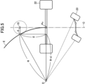
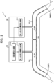
- FIG. 1 is an overall schematic diagram of the equipment required for automatic travel of a lawn mower according to one embodiment of the present invention.
- 1 is a side external view of a lawn mower according to one embodiment to which the present invention is applied;
- FIG. 1 is a top conceptual view of the main parts of a lawn mower according to one embodiment of the present invention;
- FIG. It is a figure which shows the relationship of the positional relationship of the deviation
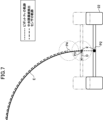
- FIG. 4 is a diagram showing geometric relationships when automatically traveling on an electromagnetic induction line;
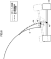
- FIG. 5 is a diagram showing the relationship between the trajectory of a pivot and the trajectory of a center guide line detection sensor;
- FIG. 5 is a diagram showing the relationship between the trajectory of a pivot and the trajectory of a center guide line detection sensor;
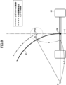
- FIG. 5 is a diagram showing the relationship between the trajectory of a pivot and the trajectory of a center guide line detection sensor;
- FIG. 5 is a diagram showing the relationship between the trajectory of a pivot and the trajectory of a center guide line detection sensor;
- 4 is a flowchart of an example steering control process according to one embodiment of the present invention; It is a figure which shows an example of a driving route. It is a figure showing the whole automatic travel system composition concerning one embodiment of the present invention.
- FIG. 3 is a diagram showing an example of an alternating current supplied to an electromagnetic induction wire and a synchronization signal;
- FIG. 4 is a comparison diagram of electric field strengths when alternating currents of adjacent closed-loop electromagnetic induction wires are in phase and when they are out of phase;
- FIG. 1 is an overall schematic diagram of devices required for automatic traveling of a lawnmower according to one embodiment of the present invention.
- a lawnmower 1 that performs lawn mowing work on a golf course while measuring the current position using the RTK-GPS system (Real Time Kinematic GPS: interferometric positioning system) is shown.
- RTK-GPS system Real Time Kinematic GPS: interferometric positioning system
- the base station 3 includes a GPS receiving device 31 and a transmitting/receiving device 32 corresponding to an RTK-GPS reference station, a GPS antenna 35, and a communication antenna 36.
- the base station 3 is installed at a point whose longitude, latitude and height are known.
- the GPS receiver 31 generates correction information for correcting the positional information error of the lawn mower 1 .
- This correction information is appropriately transmitted to the lawn mower 1 through the transmitting/receiving device 32 and the communication antenna 36 .
- the transmission timing of the correction information may be, for example, the timing requested by the lawnmower 1 or at predetermined intervals (for example, every 100 ms).
- the RTK-GPS system is used as the positioning system, but a differential GPS system (Differential GPS: relative positioning system) may also be used.
- a differential GPS system Different GPS: relative positioning system
- the lawn mower 1 includes a machine body 10, a control device 11, a vehicle speed sensor 12, an azimuth angular velocity sensor 13, a left guide wire detection sensor 14, a center guide wire detection sensor 15, a right guide wire detection sensor 16, a drive controller 17, and a GPS antenna. 18, a communication antenna 19, a cutting blade (front) 20, a cutting blade (rear) 21, a drive wheel 22, a steering wheel 23, an operation input section 24, a display section 25, and an audio output section .
- the control device 11 comprises a computer device having a CPU, communication function, storage function (drive unit and/or input/output interface for internal recording medium and external recording medium), display function (display), and a predetermined computer program.
- This computer program causes the computer device to be controlled by a GPS receiver 101, a transmitter/receiver 102, a vehicle information receiver 105, a drive commander 106, a control information generator 107, a storage 108, a removable recording medium interface 109, and a main controller 112. , to function as The main control unit 112 comprehensively controls the operation of each unit.
- This computer device has an RTC (Real Time Clock) module that outputs time data and a synchronous clock for control operations.
- the control device 11 may be provided with an azimuth angular velocity sensor for cases such as when the lawn mower is not provided with an azimuth angular velocity sensor. Details of the control device 11 will be described later.
- the vehicle speed sensor 12 detects the running speed of the lawn mower 1 when moving forward or backward.
- the azimuth angular velocity sensor 13 detects the behavior (dynamics) of the lawn mower 1 such as tilting, turning, and wobbling from angular velocities about three-dimensional axes (roll, pitch, yaw).
- the data to be measured by the azimuth angular velocity sensor 13 may be substituted by an accelerometer.
- the sensors 11 and 12 can also be substituted by taking in the measurement result of various instruments with which the lawn mower 1 is equipped.
- the three lead wire detection sensors, the center lead wire detection sensor 15, the left lead wire detection sensor 14, and the right lead wire detection sensor 16, detect the alternating current supplied to the electromagnetic lead wire when automatically traveling along the travel route on the electromagnetic lead wire. It detects the strength of the alternating magnetic field generated by the current.
- the drive control unit 17 controls a work drive mechanism that drives the mowing blades of the lawn mower 1 to move up and down, actuation, etc. based on a work control signal described later, and controls the lawn mower 1 based on a travel control signal described later. It controls the traveling drive mechanism that drives the turning to the right and left, forward movement, backward movement, etc.
- the drive control unit 17 may be provided separately from the control device 11 as illustrated, or may be implemented as one function of the control device 11 .
- the GPS antenna 18 functions as a position detection sensor that receives GPS data transmitted from GPS satellites.
- Communication antenna 19 enables communication with communication antenna 36 of base station 3 . This communication is used for sending and receiving correction information for correcting errors in the positional information of the lawn mower 1, communication with the operator of the lawn mower 1, signals for remote control of the lawn mower 1, and the like. be.
- the operation input unit 24 is composed of a keyboard, a mouse, etc., but is not limited to these.
- the display unit 25 is composed of a CRT, a liquid crystal display, a laminated display lamp, etc., but is not limited to these.
- the audio output unit 26 is composed of a speaker or the like, but is not limited to this.
- FIG. 2 is an external view of the lawn mower 1 viewed from the side.
- FIG. 3 is a top conceptual view of the main parts of a lawn mower according to one embodiment of the present invention.
- the control device 11 , the vehicle speed sensor 12 , the azimuth angular velocity sensor 13 , the drive control section 17 , the travel drive mechanism and the work drive mechanism described above are incorporated in the machine body 10 of the lawn mower 1 .
- the azimuth angular velocity sensor 13 is installed at a position where the behavior of the lawn mower 1 is correctly transmitted.
- the GPS antenna 18 is provided substantially at the center of the body of the lawn mower 1, that is, substantially at the center of the body in the longitudinal and width directions.
- the communication antenna 19 is attached so as to protrude from the rear surface of the body of the lawn mower 1 so as not to interfere with the reception of the GPS antenna 18 .
- the three guide wire detection sensors, the center guide wire detection sensor 15, the left guide wire detection sensor 14, and the right guide wire detection sensor 16, are attached to the stay 27 attached to the cutting blade (front) 20.
- the center guide line detection sensor 15 is located on the center line C of the lawn mower 1 and is separated from the pivot Pv located at the center of the axle of the drive wheel 22 that is the turning center of the lawn mower 1 by a distance l [m], which will be described later.
- the left guide wire detection sensor 14 and the right guide wire detection sensor 16 are arranged on a straight line perpendicular to the center line C of the lawn mower 1 and passing through the center guide wire detection sensor 15. on the left and right sides of the center guide wire detection sensor 15 at a distance D [m] described later.
- the lawn mower 1 includes a pair of cutting blades (front) 20 and cutting blades (rear) 21 for mowing grass.
- the front cutting blade 18 cuts grass on the left and right edges of the cutting width W [m] in the direction perpendicular to the traveling direction.
- the rear cutting blade 19 cuts the grass in the center of the cutting width W [m].
- This mowing width W [m] is the working width in which the lawn mower 1 can mow the grass in one run.
- GPS receiver 101 of control device 11 outputs GPS data received by GPS antenna 18 to control information generator 107 .
- Transmitting/receiving unit 102 enables communication between control information generating unit 107 and base station 3 via communication antenna 19, and is used to correct errors in the positional information of lawn mower 1 received by communication antenna 19.
- the correction information is output to control information generating section 107 .
- the control information generator 107 calculates the current position of the lawn mower 1 based on the GPS data received by the GPS antenna 18 and correction information for correcting errors in the position information of the lawn mower 1 received by the communication antenna 19 . Generate location information to represent.
- the transmission/reception unit 102 can be connected to any network regardless of whether it is wired or wireless, a LAN (Local Area Network), or a public communication line.
- the vehicle information receiving unit 105 acquires detection information representing the running speed, direction, and behavior of the lawn mower 1 from the vehicle speed sensor 12 and the azimuth angular velocity sensor 13, and/or position tracking by GPS data. If the acquired information is analog data, it is converted into digital data and output. At that time, if necessary, data correction is performed by removing offset components and drift components from the output of the azimuth angular velocity sensor 13 . In addition, the vehicle information receiving unit 105 acquires magnetic field intensities from the center guide wire detection sensor 15 , the left guide wire detection sensor 14 , and the right guide wire detection sensor 16 . The output information of vehicle information receiving section 105 is recorded in storage section 108 in association with the current time data.
- the drive command unit 106 determines the control contents of the travel drive mechanism or the work drive mechanism to control the travel or work of the lawn mower 1. to the drive control unit 17. Based on this information, the drive control unit 17 controls the traveling drive mechanism or work drive mechanism of the lawn mower. As a result, the lawnmower 1 can automatically travel and automatically travel to mowing the lawn.
- the storage unit 108 can record travel route and operation data, predetermined computer programs, and the like.
- the storage unit 108 is composed of an arbitrary number of storage components such as hard disks and semiconductor memories, but is not limited to these.
- a removable recording medium 40 such as an optical disc such as a CD-ROM or DVD, a USB memory, or an SD memory card can be detachably attached to the removable recording medium interface unit 109 .
- the removable recording medium interface unit 109 can read data recorded on the mounted removable recording medium 40 and write data to the removable recording medium 40 .
- the removable recording medium interface unit 109 is, for example, a dedicated reader/writer or the like if the removable recording medium 40 is an optical disc such as a CD-ROM or DVD, a USB port or the like if the removable recording medium 40 is a USB memory, or an SD memory card.
- it may be a card slot or the like, but it is not limited to these.
- the traveling route and operation data are recorded in the storage unit 108 or the removable recording medium 40 attached to the removable recording medium interface unit 109 .
- the operation data is associated with the traveling route, and the lawn mowing work including the up-and-down operation of the cutting blade (front) 20 and the cutting blade (rear) 21 while the lawn mower 1 is traveling or stopped, and starting or stopping the rotation. , including the speed of the lawnmower 1 and the automatic running mode.
- the automatic travel mode includes a positioning mode in which the vehicle automatically travels based on a received positioning signal, and an electromagnetic induction mode in which a magnetic field generated from an electromagnetic induction wire is detected and the vehicle automatically travels along the electromagnetic induction wire.
- the control information generating unit 107 controls the center guide line detection sensor 15, Based on the deviation of the lawn mower 1 from the electromagnetic induction wire E calculated from the magnetic field intensity obtained by the left induction wire detection sensor 14 and the right induction wire detection sensor 16, a travel control signal and a work control signal are generated and output. . This makes it possible to work by automatic driving.
- FIG. 4 is a diagram showing the relationship between the displacement of the induction wire detection sensor from the electromagnetic induction wire and the positional relationship between the electromagnetic induction wire and the induction wire detection sensor.
- FIG. 5 is a diagram showing the geometrical relationship when automatically traveling on electromagnetic induction lines.
- 6 to 9 are diagrams showing the relationship between the trajectory of the pivot and the trajectory of the center guide line detection sensor.
- FIG. 10 is a flowchart of an example steering control process according to one embodiment of the present invention.
- the steering control system 60 includes the control device 11 , the center guide wire detection sensor 15 , the left guide wire detection sensor 14 and the right guide wire detection sensor 16 .
- FIG. 4 is a diagram showing the relationship between the deviation of the induction wire detection sensor from the electromagnetic induction wire and the positional relationship between the electromagnetic induction wire and the induction wire detection sensor in a cross section perpendicular to the traveling direction of the lawn mower 1 .
- the vertical height from the electromagnetic induction wire E to the central induction wire detection sensor 15 is h [m]
- the horizontal displacement of the central induction wire detection sensor 15 from the electromagnetic induction wire E is Let d [m] be the horizontal distance from the electromagnetic induction wire E to the central induction wire detection sensor 15, and ⁇ be the angle between the central induction wire detection sensor 15 and a vertical straight line passing through the electromagnetic induction wire.
- the value of the horizontal distance d to the detection sensor 15 is proportional to the distance r [m] from the electromagnetic induction wire E to the central induction wire detection sensor 15 .
- the strength of the magnetic field emitted from the electromagnetic induction wire E is inversely proportional to the distance r [m] from the electromagnetic induction wire E to the central induction wire detection sensor 15, the larger the r [m], the more the central induction wire detection sensor The magnetic field detected by 15 becomes weaker.
- the maximum value of r[m] that can be detected by the central guiding wire detection sensor 15 Since the value of d[m] is proportional to the value of r[m], the maximum value of d[m] that can be detected by the central guide wire detection sensor 15 can also be determined.
- This maximum detectable horizontal distance d[m] is called the maximum detectable distance D[m].
- the detection performance of the left guide wire detection sensor 14 and the right guide wire detection sensor 16 is the same, and the maximum detection distance is also D [m].
- the center guide wire detection sensor 15 is arranged on the center line C of the lawn mower 1 at a distance l [m] from the pivot Pv, and the left guide wire detection sensor 14 and the right guide wire detection sensor 14 are arranged at a distance l [m] from the pivot Pv.
- the sensors 16 are arranged on a straight line perpendicular to the center line C of the lawn mower 1 and passing through the central guiding wire detection sensor 15, on the left and right sides of the central guiding wire detecting sensor 15, and at the maximum detection distance D from the central guiding wire detecting sensor 15. are arranged at positions separated by [m]. Since the central guiding wire detection sensor 15, the left guiding wire detecting sensor 14, and the right guiding wire detecting sensor 16 have the same detection performance, with such arrangement, from the electromagnetic guiding wire E at the position of the central guiding wire detecting sensor 15 deviation can be detected.
- the control information generation unit 107 of the control device 11 is detection data acquired by the center guide line detection sensor 15, the left guide line detection sensor 14, and the right guide line detection sensor 16, which are acquired by the vehicle information reception unit 105.
- the deviation of the lawn mower 1 from the electromagnetic induction line E is calculated based on the magnetic field intensity. Specifically, when the central guiding wire detection sensor 15 does not detect a magnetic field and the left guiding wire detecting sensor 14 detects a magnetic field, the electromagnetic guiding wire E is positioned to the left of the left guiding wire detecting sensor 14. It can be determined that there is deviation.
- the electromagnetic guiding wire E is shifted to the right side of the right guiding wire detecting sensor 16. can be determined. Then, when the central induction wire detection sensor 15 detects a magnetic field and the left induction wire detection sensor 14 detects a magnetic field, the electromagnetic induction wire E is positioned between the central induction wire detection sensor 15 and the left induction wire detection sensor 14.
- the control information generation unit 107 when the lawn mower 1 (more precisely, the position of the central guide wire detection sensor 15) is displaced from the electromagnetic induction wire E, the allowable deviation width for stopping the lawn mower 1 is set.
- the control information generation unit 107 When the maximum detection distance D [m] is set and the central guide wire detection sensor 15 does not detect the magnetic field, the control information generation unit 107 generates a travel control signal for stopping the lawn mower 1, and mowing the lawn. Stop machine 1.
- the calculation of the deviation of the lawn mower 1 from the electromagnetic induction line E is not limited to the configuration calculated by the control information generation unit 107.
- the calculated deviation is calculated outside the control device 11. may be any other suitable configuration, such as a configuration in which the controller receives the .
- the central induction wire detection sensor 15 may not be arranged.
- the pivot (control point) Pv of the lawn mower 1 is set so that the point (turning center O) at which the normal lines of the steered wheels intersect is the radius R. Move along the arc trajectory.
- the central guide wire detection sensor 15 which will be considered below, is located within the range of the position of the lawn mower 1 in the longitudinal direction. is omitted in FIG.
- the control information generation unit 107 calculates the magnetic field intensity obtained by the central guide wire detection sensor 15, the left guide wire detection sensor 14, and the right guide wire detection sensor 16, and the electromagnetic induction wire E of the lawn mower 1
- a travel control signal is generated and output based on the deviation of the .
- the control information generation unit 107 generates a turf calculated from the magnetic field strength acquired by the central guide wire detection sensor 15, the left guide wire detection sensor 14, and the right guide wire detection sensor 16 for each control cycle t [seconds].
- a travel control signal is generated and output to turn the mower 1 or to move the mower 1 straight so as to cancel the deviation.
- the output travel control signal is sent to the drive control unit 17 via the drive command unit 106, and the drive control unit 17 controls the drive wheels 22 and turns the steered wheels 23 according to the received travel control signal.
- the lawn mower 1 does not move backward when traveling on the electromagnetic induction wire.
- the traveling route must not include a curve with a radius of curvature smaller than the minimum turning radius.
- the lawn mower 1 can travel on a curve with a minimum turning radius or more. Therefore, the limit of whether or not the lawnmower 1 can automatically travel without deviating from the electromagnetic induction line can be considered as an arc having a radius equal to the minimum turning radius.
- the control information generator 107 does not detect deviation, so the steering control system 60 does not steer and the lawn mower 1 runs straight. .
- the speed at which the lawn mower 1 travels on the electromagnetic induction wire E is v [m/sec]
- the pivot Pv and the central induction wire detection sensor 15 are at the initial position It will be the position P1 which is straight ahead from P0 by tv [m].
- the control information generator 107 detects a deviation from the electromagnetic induction line E, so the steering control system 60 causes the lawn mower 1 to approach the electromagnetic induction line with a minimum turn. In other words, steer to turn to the left with the minimum turning radius.
- the pivot Pv is at the position P1 at this time, as can be seen from FIG. It is not possible to return to the electromagnetic induction line E. That is, the lawn mower 1 cannot return to the electromagnetic induction wire E because the turning timing is too late.
- the central guiding wire detection sensor 15 detects that the position of the central guiding wire detection sensor 15 is deviated to the right from the electromagnetic induction wire E, so the steering control system 60 starts mowing the lawn.
- the aircraft 1 is steered so as to approach the electromagnetic guidance line with a minimum turn, that is, turn to the left with a minimum turning radius.
- the pivot Pv is at the position P3, so that the lawn mower 1 turns with the minimum turn, so that the lawn mower 1 moves on the electromagnetic induction line E without deviating from the electromagnetic induction line E, as can be seen from FIG. can run.
- the lawn mower 1 cannot return to the electromagnetic induction wire E when the center induction wire detection sensor 15 is away from the pivot Pv by a distance smaller than tv [m]. can be understood by comparing
- the central guiding line detection sensor 15 in the initial position, the central guiding line detection sensor 15 is positioned to the right in the direction perpendicular to the center line C of the lawn mower 1.
- P5 be the initial position of the pivot Pv
- P6 be the initial position of the center guide line detection sensor 15 .
- the central guiding line detection sensor 15 detects that the position of the central guiding line detection sensor 15 is deviated to the right from the electromagnetic guidance line E, so the steering control system 60 causes the lawn mower 1 to move to the minimum position.
- steer to approach the electromagnetic induction line that is, to turn to the left with the minimum turning radius.
- the position of the pivot Pv is a position P7 advanced by a distance tv [m] on the circumference of the minimum turning radius R, and the position of the center guide line detection sensor 15 is from the position P7. , to a position P8 that is tv [m] away in the tangential direction of the circumference of the minimum turning radius R at the position P7.
- the position of the central guiding wire detection sensor 15 is still deviated to the right from the electromagnetic guiding wire E.
- the steering control system 60 steers the mower 1 again to approach the electromagnetic guideline with a minimum turn, ie turn to the left with a minimum turn radius.
- the lawn mower 1 can return to the electromagnetic induction wire E by repeating such steering for each control cycle.
- the center guide line detection sensor 15 is located on the center line C of the lawn mower 1 at a distance tv [m] away from the pivot Pv.
- the center guide line detection sensor 15 is positioned on the center line C of the lawn mower 1 at a distance from the pivot Pv. , and in the initial position, the center guide line detection sensor 15 is located at a distance of the permissible deviation width D [m] to the right in the direction perpendicular to the center line C of the lawn mower 1.
- P9 be the initial position of the pivot Pv
- P10 be the initial position of the central guiding wire detection sensor 15 .
- the control information generation unit 107 detects that the position of the central guide line detection sensor 15 is shifted to the right from the electromagnetic guide line E, so the steering control system 60 causes the lawn mower 1 to move to the minimum turning position. steer to approach the electromagnetic induction line, that is, to turn to the left with the minimum turning radius. Therefore, the lawn mower 1 runs on the electromagnetic induction line E with the minimum turning radius.
- the trajectory of the central guide line detection sensor 15 becomes parallel to the electromagnetic guide line E of the minimum turning radius R, that is, it cannot approach the electromagnetic guide line E, but it does not move away from it. Therefore, even if the vehicle is steered to turn to the left with the minimum turning radius in each control cycle, the trajectory of the central guidance line detection sensor 15 remains parallel to the electromagnetic guidance line E with the minimum turning radius R.
- the central guidance line detection sensor 15 is placed farthest from the pivot Pv.
- the position of the guide wire detection sensor 15 is such that the center guide wire detection sensor 15 is on the center line C of the lawn mower 1 and is at a distance from the pivot Pv. It can be seen that the positions are separated by
- l [m] is greater than or equal to tv [m]
- three lead wire detection sensors, the center lead wire detection sensor 15, the left lead wire detection sensor 14, and the right lead wire detection sensor 16 detect the electromagnetic lead wire E at the position of the center lead wire detection sensor 15. deviation was detected. That is, the detection reference point for deviation from the electromagnetic induction wire E detected by the three induction wire detection sensors of the central induction wire detection sensor 15, the left induction wire detection sensor 14, and the right induction wire detection sensor 16 is the central induction wire It was the position of the detection sensor 15 .
- the detection reference point for the deviation from the electromagnetic induction wire E detected by the plurality of induction wire detection sensors is the above condition (tv [m] that's all, below), the deviation detection reference point deviates from the electromagnetic induction line by more than the allowable width D [m] It is also understood that automatic driving is possible without
- the vehicle information receiving unit 105 acquires the magnetic field intensity, which is the detection data acquired by each lead wire detection sensor, from the center guide wire detection sensor 15, the left guide wire detection sensor 14, and the right guide wire detection sensor 16 (S1 ).
- the control information generation unit 107 generates an electromagnetic field of the lawn mower 1 calculated from the magnetic field intensities obtained by the central guide wire detection sensor 15, the left guide wire detection sensor 14, and the right guide wire detection sensor 16 for each control cycle t [seconds]. Based on the deviation from the guide line E, a travel control signal is generated and output to turn the lawn mower 1 so as to cancel the deviation or to make the lawn mower 1 go straight (S2). The output travel control signal is sent to the drive control unit 17 via the drive command unit 106, and the drive control unit 17 controls the drive wheels 22 according to the received travel control signal to turn the steered wheels 23 ( S3).
- the configuration of the induction wire detection sensor is the electromagnetic induction wire E detected by three induction wire detection sensors: the central induction wire detection sensor 15, the left induction wire detection sensor 14, and the right induction wire detection sensor 16.
- the reference point for detecting the deviation from the center guide line detection sensor 15 is the position of the center guide line detection sensor 15, the front wheels are the driving wheels, the rear wheels are the steering wheels, and the pivot Pv is located at the center of the axle of the driving wheels.
- the detection reference point of the deviation from the electromagnetic induction line E detected by the plurality of induction line detection sensors is tv [m] or more, and Any appropriate configuration of the guide wire detection sensor and the vehicle can be used as long as the guide wire detection sensor is arranged at a position forward of the pivot Pv by a horizontal distance l [m] that satisfies the following.
- the permissible deviation width is set as the maximum detection distance of the central guiding line detection sensor, but the permissible deviation width does not have to be the maximum detection distance of the central guiding line detection sensor, and may be any appropriate width. be able to.
- Some functions of the steering control system may be configured separately from the cruise control device, such as a separate server, base station, tablet computer, or the like.
- FIG. 11 is a diagram showing an example of a travel route.
- FIG. 12 is a diagram showing the overall configuration of an automatic driving system according to one embodiment of the present invention.
- FIG. 13 is a diagram showing an example of an alternating current supplied to an electromagnetic induction wire and a synchronization signal.
- FIG. 14 is a comparison diagram of the electric field intensity when the alternating currents of the adjacent closed-loop electromagnetic induction wires are in phase and when they are out of phase.
- FIG. 11 is a diagram showing an example of a travel route, in which the driver enters the hall H from the cart path CP, mows the lawn in the hall H, returns to the cart path CP again from the hall H, proceeds along the cart path CP, and travels along the cart path CP.
- FIG. 12 is a diagram showing the overall configuration of the automatic driving system according to one embodiment of the present invention, which is an enlarged view from the vicinity of the switching point SWP1 to the vicinity of the switching point SWP2.
- the automatic driving system 5 includes a first power supply device corresponding to the first closed-loop electromagnetic induction wire CL1, the second closed-loop electromagnetic induction wire CL2, the first closed-loop electromagnetic induction wire CL1, and the second closed-loop electromagnetic induction wire CL2. 51 , including a second power supply 52 .
- the first closed-loop electromagnetic induction line CL1 and the second closed-loop electromagnetic induction line CL2 are arranged adjacent to each other.
- a first power supply 51 and a second power supply 52 are connected to the first closed-loop electromagnetic induction line CL1 and the second closed-loop electromagnetic induction line CL2, respectively.
- the first power supply device 51 includes a first alternating current generator 511 and a synchronization signal generator 513 .
- the second power supply device 52 also includes a second alternating current generator 521 .
- the first AC current generator 511 and the second AC current generator 521 generate low-frequency AC currents of the same frequency.
- a square wave alternating current of 1.5 kHz is generated as shown in FIG. can be any other suitable shape of alternating current.
- the synchronization signal generator 513 generates a synchronization signal at a predetermined timing.
- the synchronization signal generated by the synchronization signal generator 513 is supplied to the second alternating current generator 521, and the second alternating current generator 521 generates the first signal at a predetermined timing based on the synchronization signal.
- a rectangular wave alternating current is generated in synchronization with the rectangular wave alternating current generated by the alternating current generator 511 . In this manner, the rectangular wave alternating current generated by the first alternating current generator 511 and the rectangular wave alternating current generated by the second alternating current generator 521 are synchronized at a predetermined timing.
- the travel route TP from the switching point SWP1 to the switching point SWP2 is on the electromagnetic induction line.
- the first portion CL1P of the first closed-loop electromagnetic induction wire CL1 and the first portion CL2P of the second closed-loop electromagnetic induction wire CL2 are arranged adjacent to each other so as to form the traveling path TP. It is At both ends of the first portion CL1P of the first closed-loop electromagnetic induction wire CL1 and both ends of the first portion CL2P of the second closed-loop electromagnetic induction wire CL2, the first closed-loop electromagnetic induction wire CL1 and the second closed-loop electromagnetic induction
- the line CL2 is bent at right angles, and the bent portion forms a straight line on the cart path CP.
- the first closed-loop electromagnetic induction wire CL1 and the second closed-loop electromagnetic induction wire CL2 can be closely adjacent to each other, and the interval between the electromagnetic induction wires on the travel route TP can be reduced. Also, the lawn mower 1 can be prevented from being guided in the bent direction of the first closed-loop electromagnetic induction line CL1 or the second closed-loop electromagnetic induction line CL2, instead of the direction of the travel path TP.
- the alternating current generated by the first alternating current generator 511 and the second closed-loop electromagnetic induction line CL2 are shifted, the alternating magnetic fields generated from the alternating currents in the vicinity of adjacent portions partially cancel each other, as shown in the diagram on the right side of FIG. , the strength of the magnetic field decreases, and the induction wire detection sensors become unable to detect the magnetic field, making it difficult to continue running.
- the magnetic field strength near the adjacent portion is reduced to It is possible to suppress the decrease (see the diagram on the left side of FIG. 14) and continue running.
- the number of adjacent closed-loop electromagnetic induction wires forming the travel route TP is limited to two. instead, it can be any other suitable number.
- the switching points SWP1 and SWP2 are set at positions where positioning signals from GPS satellites can be received satisfactorily.
- the automatic traveling mode is switched from the positioning mode to the electromagnetic induction mode, and automatic traveling is performed by electromagnetic induction.
- the switching point SWP2 is reached, the automatic traveling mode is switched from the electromagnetic induction mode to the positioning mode, and automatic traveling is performed by positioning (GPS) to head for the garage W.
- the switching of the automatic driving mode is performed by a driving control signal generated by the control information generation unit 107 based on the driving route and operation data recorded in the storage unit 108 or the removable recording medium 40 attached to the removable recording medium interface unit 109. done.
- the electromagnetic induction wire can be used over a long distance. Automatic driving becomes possible.
- a recording medium recording a computer program that implements the method of the above embodiment may be supplied to the control device 10 .
- the object of the present invention can be achieved by the computer of the control device 10 reading and executing the computer program recorded on the recording medium. Therefore, since the computer program itself read from the recording medium implements the method of the present invention, the computer program constitutes the present invention.
- the present invention is also applicable to sprinklers, spreaders, fertilizers, seeders, soil condition measuring machines, harvesters, cultivators, and cultivated soil. It is applicable to any other suitable vehicle such as machines, agricultural machines including soil tillers, cleaning machines, carts and the like.
- the positioning signal used in the positioning mode is GPS data, but the positioning signal used in the positioning mode is not limited to this. Any other appropriate positioning signals such as beacon signals, BLE beacon signals, impulse UWB (IR-UWB) signals, IMES (Indoor Messaging System) signals, or a combination of all or part of them, transmitted from access points can do.
- Any other appropriate positioning signals such as beacon signals, BLE beacon signals, impulse UWB (IR-UWB) signals, IMES (Indoor Messaging System) signals, or a combination of all or part of them, transmitted from access points can do.
- Reference Signs List 1 Lawn mower 10 Main body 11 Control device 12 Vehicle speed sensor 13 Azimuth angular velocity sensor 14 Left guide wire detection sensor 15 Central guide wire detection sensor 16 ... right guide wire detection sensor 17 ... drive control unit 18 ... GPS antenna 19 ... communication antenna 20 ... cutting blade (front) 21 Cutting blade (rear) 22... Driving wheel 23... Steering wheel 24... Operation input unit 25... Display unit 26... Audio output unit 27... Stay 101... GPS receiving unit 102... Transmitting/receiving unit 105... Vehicle information receiving unit 106... Driving command unit 107... Control information generating unit 108... Storage unit 109... Removable recording medium interface unit 112... Main control unit 3...
Abstract
A steering control system for a vehicle that detects magnetic fields generated from electromagnetic induction lines and that is capable of autonomous travelling along the electromagnetic induction lines, the steering control system including: a plurality of induction line detection sensors attached to the vehicle; and a control device that, for every control cycle and on the basis of a shift of the vehicle from the electromagnetic induction lines calculated from detection data acquired by the plurality of induction line detection sensors, generates a travelling control signal that causes the vehicle to turn so as to eliminate the shift or causes the vehicle to advance forward, and outputs the travelling control signal. A shift detection reference point of the plurality of induction line detection sensors is disposed at a position separated forward from a pivot serving as the turning center of the vehicle, by a distance l [m] in a horizontal direction. When the control cycle is t [sec], a velocity when the vehicle is travelling on the electromagnetic induction lines is v [m/sec], a shift tolerance width in the horizontal direction from the electromagnetic induction lines of the shift detection reference point is D [m], and a smallest turning radius of the vehicle is R [m], the distance l [m] is at least tv [m] and no greater than equation (1).
Description
本発明は、自動走行車両、自動走行車両の操舵制御のためのシステム、方法、プログラム、プログラムを記録した記録媒体、自動走行システムに関する。
The present invention relates to an automated driving vehicle, a system, a method, a program, a recording medium recording the program, and an automated driving system for steering control of the automated driving vehicle.
路面に埋設した電磁誘導線に交流電流を供給し、これにより発生する交流磁界を、車両の中心線に対して左右に等間隔で配置した2つの磁気センサによって検出し、2つの磁気センサに発生する誘起起電力を検出して電磁誘導線の位置を判断して、判断された電磁誘導線の位置に基づいて操舵を行い、車両を電磁誘導線に沿って走行させる自動走行システムが知られている(例えば、特許文献1参照)。
An alternating current is supplied to an electromagnetic induction wire embedded in the road surface, and the resulting alternating magnetic field is detected by two magnetic sensors placed at equal intervals to the left and right of the center line of the vehicle. An automatic driving system is known in which an induced electromotive force is detected, the position of an electromagnetic induction line is determined, steering is performed based on the determined position of the electromagnetic induction line, and the vehicle travels along the electromagnetic induction line. (See Patent Document 1, for example).
しかしながら、上記特許文献1に記載されているような従来の電磁誘導線による自動走行システムは、(1)大規模な敷設工事が必要なこと、(2)電磁誘導線経路以外の経路は自動走行させることができないこと、(3)長距離の電磁誘導線へ電力を供給する必要があるため電力を供給する電源が大規模なものとなること等の問題がある。
However, the conventional automatic driving system using electromagnetic induction wires as described in Patent Document 1 has the following drawbacks: (1) large-scale installation work is required; (3) Since it is necessary to supply power to a long-distance electromagnetic induction wire, a large-scale power supply is required.
また、電磁誘導線による自動走行システムにおいては、車両が電磁誘導線から逸脱しないような制御を行う必要がある。
Also, in an automated driving system that uses electromagnetic induction lines, it is necessary to control the vehicle so that it does not deviate from the electromagnetic induction lines.
そこで、本発明は、大規模な敷設工事や大規模な電源の必要ない電磁誘導による自動走行システムを提供ことを目的の1つとする。
Therefore, one of the objects of the present invention is to provide an automatic driving system using electromagnetic induction that does not require large-scale installation work or a large-scale power supply.
また、本発明は、車両が電磁誘導線から逸脱しないような制御を可能とすることを目的の1つとする。
Another object of the present invention is to enable control so that the vehicle does not deviate from the electromagnetic induction line.
本発明の1つの態様は、電磁誘導線から発生する磁界を検出して前記電磁誘導線に沿って自動走行可能な車両のための操舵制御システムであって、前記車両に取り付けられた複数の誘導線検出センサと、制御サイクル毎に、前記複数の誘導線検出センサにより取得された検出データから算出した前記車両の前記電磁誘導線からのずれに基づいて、そのずれを打ち消すように前記車両を旋回させ、又は前記車両を直進させるような走行制御信号を生成し、出力する制御装置と、を備え、前記複数の誘導線検出センサのずれ検出基準点が、前記車両の旋回中心となるピボットから水平方向の距離l[m]だけ前方側に離れた位置に配置されており、前記距離l[m]は、前記制御サイクルをt[秒]、前記車両が前記電磁誘導線上を走行する時の速度をv[m/秒]、前記ずれ検出基準点の前記電磁誘導線からの水平方向のずれ許容幅をD[m]、前記車両の最小旋回半径をR[m]としたとき、tv[m]以上かつ
 以下である操舵制御システムを提供するものである。
One aspect of the present invention is a steering control system for a vehicle capable of automatically traveling along the electromagnetic induction wire by detecting a magnetic field generated from the electromagnetic induction wire, comprising a plurality of induction wires attached to the vehicle. Based on the deviation of the vehicle from the electromagnetic induction line calculated from the detection data acquired by the line detection sensor and the plurality of induction line detection sensors in each control cycle, the vehicle is turned so as to cancel the deviation. and a control device for generating and outputting a travel control signal for causing the vehicle to travel straight, wherein the deviation detection reference point of the plurality of guide line detection sensors is positioned horizontally from a pivot serving as a turning center of the vehicle. The distance l [m] corresponds to the control cycle of t [seconds] and the speed when the vehicle travels on the electromagnetic induction line. is v [m/sec], the permissible width of deviation of the deviation detection reference point in the horizontal direction from the electromagnetic induction line is D [m], and the minimum turning radius of the vehicle is R [m], tv [m ] or more and
以下である操舵制御システムを提供するものである。
One aspect of the present invention is a steering control system for a vehicle capable of automatically traveling along the electromagnetic induction wire by detecting a magnetic field generated from the electromagnetic induction wire, comprising a plurality of induction wires attached to the vehicle. Based on the deviation of the vehicle from the electromagnetic induction line calculated from the detection data acquired by the line detection sensor and the plurality of induction line detection sensors in each control cycle, the vehicle is turned so as to cancel the deviation. and a control device for generating and outputting a travel control signal for causing the vehicle to travel straight, wherein the deviation detection reference point of the plurality of guide line detection sensors is positioned horizontally from a pivot serving as a turning center of the vehicle. The distance l [m] corresponds to the control cycle of t [seconds] and the speed when the vehicle travels on the electromagnetic induction line. is v [m/sec], the permissible width of deviation of the deviation detection reference point in the horizontal direction from the electromagnetic induction line is D [m], and the minimum turning radius of the vehicle is R [m], tv [m ] or more and
There is provided a steering control system which is:
前記複数の誘導線検出センサは、中央誘導線検出センサ、左側誘導線検出センサ、及び右側誘導線検出センサであり、前記ずれ検出基準点が前記車両の中央線上に配置され、中央誘導線検出センサが前記すれ検出基準点に配置され、前記左側誘導線検出センサ及び前記右側誘導線検出センサが、前記車両の中央線に垂直で前記中央誘導線検出センサを通る直線上に、前記中央誘導線検出センサの左側と右側にそれぞれ配置されているものとすることができる。
The plurality of guide line detection sensors are a center guide line detection sensor, a left guide line detection sensor, and a right guide line detection sensor, and the deviation detection reference point is arranged on the center line of the vehicle, and the center guide line detection sensor is is arranged at the rubbing detection reference point, and the left guide line detection sensor and the right guide line detection sensor are arranged on a straight line perpendicular to the center line of the vehicle and passing through the center guide line detection sensor. They can be arranged on the left and right sides of the sensor, respectively.
前記ずれ許容幅は、前記中央誘導線検出センサから、前記中央誘導線検出センサの前記磁界を検出可能な最大の水平方向の距離である最大検出距離であるものとすることができる。
The permissible deviation width can be a maximum detection distance, which is a maximum horizontal distance at which the magnetic field of the central guiding wire detection sensor can be detected from the central guiding wire detecting sensor.
前記車両は、前輪と後輪とを備え、前記前輪が、駆動輪であり、前記後輪が、操舵輪であり、前記前輪の車軸の中心が前記ピボットであるものとすることができる。
The vehicle may have front wheels and rear wheels, the front wheels being drive wheels, the rear wheels being steering wheels, and the center of the axle of the front wheels being the pivot.
本発明の1つの態様は、前記操舵制御システムから出力される前記走行制御信号に基づいて自己の走行を駆動する走行駆動機構を含む車両を提供するものである。
One aspect of the present invention provides a vehicle including a travel drive mechanism that drives the vehicle to travel based on the travel control signal output from the steering control system.
本発明の1つの態様は、電磁誘導線から発生する磁界を検出して前記電磁誘導線に沿って自動走行可能な車両のための操舵制御方法であって、前記車両には、複数の誘導線検出センサが取り付けられており、制御サイクル毎に、前記複数の誘導線検出センサにより取得された検出データから算出した前記車両の前記電磁誘導線からのずれに基づいて、そのずれを打ち消すように前記車両を旋回させ、又は前記車両を直進させるような走行制御信号を生成し、出力し、前記複数の誘導線検出センサのずれ検出基準点が、前記車両の旋回中心となるピボットから水平方向の距離l[m]だけ前方側に離れた位置に配置されており、前記距離l[m]は、前記制御サイクルをt[秒]、前記車両が前記電磁誘導線上を走行する時の速度をv[m/秒]、前記ずれ検出基準点の前記電磁誘導線からの水平方向のずれ許容幅をD[m]、前記車両の最小旋回半径をR[m]としたとき、tv[m]以上かつ
 以下である操舵制御方法を提供するものである。
One aspect of the present invention is a steering control method for a vehicle capable of automatically traveling along the electromagnetic induction wire by detecting a magnetic field generated from the electromagnetic induction wire, wherein the vehicle has a plurality of induction wires. A detection sensor is attached, and based on the deviation of the vehicle from the electromagnetic induction line calculated from the detection data acquired by the plurality of induction line detection sensors, the deviation is canceled in each control cycle. generating and outputting a travel control signal for causing the vehicle to turn or for causing the vehicle to go straight, wherein a deviation detection reference point of the plurality of guide line detection sensors is a horizontal distance from a pivot serving as a turning center of the vehicle; The distance l [m] corresponds to the control cycle of t [seconds] and the speed of the vehicle traveling on the electromagnetic induction line v [ m/sec], the permissible width of deviation of the deviation detection reference point in the horizontal direction from the electromagnetic induction line is D [m], and the minimum turning radius of the vehicle is R [m], tv [m] or more, and
以下である操舵制御方法を提供するものである。
One aspect of the present invention is a steering control method for a vehicle capable of automatically traveling along the electromagnetic induction wire by detecting a magnetic field generated from the electromagnetic induction wire, wherein the vehicle has a plurality of induction wires. A detection sensor is attached, and based on the deviation of the vehicle from the electromagnetic induction line calculated from the detection data acquired by the plurality of induction line detection sensors, the deviation is canceled in each control cycle. generating and outputting a travel control signal for causing the vehicle to turn or for causing the vehicle to go straight, wherein a deviation detection reference point of the plurality of guide line detection sensors is a horizontal distance from a pivot serving as a turning center of the vehicle; The distance l [m] corresponds to the control cycle of t [seconds] and the speed of the vehicle traveling on the electromagnetic induction line v [ m/sec], the permissible width of deviation of the deviation detection reference point in the horizontal direction from the electromagnetic induction line is D [m], and the minimum turning radius of the vehicle is R [m], tv [m] or more, and
The present invention provides a steering control method which is as follows.
前記複数の誘導線検出センサは、中央誘導線検出センサ、左側誘導線検出センサ、及び右側誘導線検出センサであり、前記ずれ検出基準点が前記車両の中央線上に配置され、中央誘導線検出センサが前記すれ検出基準点に配置され、前記左側誘導線検出センサ及び前記右側誘導線検出センサが、前記車両の中央線に垂直で前記中央誘導線検出センサを通る直線上に、前記中央誘導線検出センサの左側と右側にそれぞれ配置されているものとすることができる。
The plurality of guide line detection sensors are a center guide line detection sensor, a left guide line detection sensor, and a right guide line detection sensor, and the deviation detection reference point is arranged on the center line of the vehicle, and the center guide line detection sensor is is arranged at the rubbing detection reference point, and the left guide line detection sensor and the right guide line detection sensor are arranged on a straight line perpendicular to the center line of the vehicle and passing through the center guide line detection sensor. They can be arranged on the left and right sides of the sensor, respectively.
前記ずれ許容幅は、前記中央誘導線検出センサから、前記中央誘導線検出センサの前記磁界を検出可能な最大の水平方向の距離である最大検出距離であるものとすることができる。
The permissible deviation width can be a maximum detection distance, which is a maximum horizontal distance at which the magnetic field of the central guiding wire detection sensor can be detected from the central guiding wire detecting sensor.
前記車両は、前輪と後輪とを備え、前記前輪が、駆動輪であり、前記後輪が、操舵輪であり、前記前輪の車軸の中心が前記ピボットであるものとすることができる。
The vehicle may have front wheels and rear wheels, the front wheels being drive wheels, the rear wheels being steering wheels, and the center of the axle of the front wheels being the pivot.
本発明の1つの態様は、前記操舵制御方法をコンピュータに実行させるためのコンピュータプログラムを提供するものである。
One aspect of the present invention provides a computer program for causing a computer to execute the steering control method.
本発明の1つの態様は、前記コンピュータプログラムを記録したコンピュータ読み取り可能な記録媒体を提供するものである。
One aspect of the present invention provides a computer-readable recording medium recording the computer program.
本発明の1つの態様は、電磁誘導線から発生する磁界を検出して前記電磁誘導線に沿って自動走行可能な車両のための自動走行システムであって、互いに隣接して配置された、複数の閉ループ電磁誘導線と、前記複数の閉ループ電磁誘導線にそれぞれ対応する電源装置と、を含み、前記複数の閉ループ電磁誘導線の各々の一部が、走行経路を形成するように、互いに隣接して配置され、前記複数の閉ループ電磁誘導線毎に対応する電源装置がそれぞれ接続され、前記電源装置から前記複数の閉ループ電磁誘導線に同じ周波数の低周波の交流電流が供給される自動走行システムを提供するものである。
One aspect of the present invention is an automatic traveling system for a vehicle capable of automatically traveling along an electromagnetic induction wire by detecting a magnetic field generated from the electromagnetic induction wire, wherein a plurality of and power supply devices respectively corresponding to the plurality of closed-loop electromagnetic induction wires, wherein a portion of each of the plurality of closed-loop electromagnetic induction wires are adjacent to each other so as to form a travel path A power supply device corresponding to each of the plurality of closed-loop electromagnetic induction wires is connected, and a low-frequency alternating current of the same frequency is supplied from the power supply device to the plurality of closed-loop electromagnetic induction wires. It provides.
前記同じ周波数の低周波の交流電流は、同期が取られているものとすることができる。
The low-frequency alternating currents of the same frequency may be synchronized.
前記車両は、自動走行モードとして、受信した測位信号に基づいて自動走行を行う測位モードと、電磁誘導線から発生する磁界を検出して前記電磁誘導線に沿って自動走行を行う電磁誘導モードを有し、前記電磁誘導線が敷設されていない経路は、前記測位モードで自動走行が行われるものとすることができる。
The vehicle has two automatic driving modes: a positioning mode for automatically driving based on the received positioning signal, and an electromagnetic induction mode for automatically driving along the electromagnetic induction wire by detecting a magnetic field generated from the electromagnetic induction wire. and the route on which the electromagnetic induction wire is not installed can be automatically driven in the positioning mode.
走行経路のうちの、測位信号を受信できない、又は測位信号の受信強度が弱い部分に前記電磁誘導線が敷設されているものとすることができる。
The electromagnetic induction wire can be laid in a portion of the travel route where the positioning signal cannot be received or the reception strength of the positioning signal is weak.
前記車両は、請求項5又は6に記載の車両であるものとすることができる。
The vehicle may be the vehicle described in claim 5 or 6.
上記構成を有する本発明によれば、大規模な敷設工事や大規模な電源の必要ない電磁誘導による自動走行システムを提供ことができる。
According to the present invention having the above configuration, it is possible to provide an automatic driving system using electromagnetic induction that does not require large-scale installation work or a large-scale power source.
また、上記構成を有する本発明によれば、車両が電磁誘導線から逸脱しないような制御を可能とすることができる。
Also, according to the present invention having the above configuration, it is possible to perform control so that the vehicle does not deviate from the electromagnetic induction line.
以下、本発明の操舵制御システム、操舵制御システムを搭載した車両、自動走行システムを、ゴルフ場の芝刈りを行う芝刈り機に適用した場合を一例として説明する。
A case where the steering control system, the vehicle equipped with the steering control system, and the automatic driving system of the present invention are applied to a lawn mower for mowing a golf course will be described below as an example.
<全体概要>
図1は、本発明の1つの実施形態に係る、芝刈り機の自動走行に必要となる装置類の全体概要図である。本実施形態では、RTK-GPS方式(Real Time Kinematic GPS:干渉測位方式)を用いて、現在位置の計測を行いながらゴルフ場の芝刈り作業を行う芝刈り機1の例を示す。 <Overall overview>
FIG. 1 is an overall schematic diagram of devices required for automatic traveling of a lawnmower according to one embodiment of the present invention. In this embodiment, an example of alawnmower 1 that performs lawn mowing work on a golf course while measuring the current position using the RTK-GPS system (Real Time Kinematic GPS: interferometric positioning system) is shown.
図1は、本発明の1つの実施形態に係る、芝刈り機の自動走行に必要となる装置類の全体概要図である。本実施形態では、RTK-GPS方式(Real Time Kinematic GPS:干渉測位方式)を用いて、現在位置の計測を行いながらゴルフ場の芝刈り作業を行う芝刈り機1の例を示す。 <Overall overview>
FIG. 1 is an overall schematic diagram of devices required for automatic traveling of a lawnmower according to one embodiment of the present invention. In this embodiment, an example of a
基地局3は、RTK-GPSの基準局に相当するGPS受信装置31及び送受信装置32と、GPSアンテナ35と、通信アンテナ36とを備えている。基地局3は、その経度、緯度、高さが既知の地点に設置される。GPS受信装置31は、芝刈り機1の位置情報の誤差を補正するための補正情報を生成する。この補正情報は、送受信装置32及び通信アンテナ36を通じて、芝刈り機1へ適宜送信される。補正情報の送信タイミングは、例えば、芝刈り機1が要求するタイミングであったり、所定の間隔(例えば100ms毎)であったりする。
The base station 3 includes a GPS receiving device 31 and a transmitting/receiving device 32 corresponding to an RTK-GPS reference station, a GPS antenna 35, and a communication antenna 36. The base station 3 is installed at a point whose longitude, latitude and height are known. The GPS receiver 31 generates correction information for correcting the positional information error of the lawn mower 1 . This correction information is appropriately transmitted to the lawn mower 1 through the transmitting/receiving device 32 and the communication antenna 36 . The transmission timing of the correction information may be, for example, the timing requested by the lawnmower 1 or at predetermined intervals (for example, every 100 ms).
本実施形態においては、測位方式として、RTK-GPS方式を用いているが、デファレンシャルGPS方式(Differential GPS:相対測位方式)を用いてもよい。
In this embodiment, the RTK-GPS system is used as the positioning system, but a differential GPS system (Differential GPS: relative positioning system) may also be used.
芝刈り機1は、機体10、制御装置11、車速センサ12、方位角速度センサ13、左側誘導線検出センサ14、中央誘導線検出センサ15、右側誘導線検出センサ16、駆動制御部17、GPSアンテナ18、通信アンテナ19、刈り刃(前方)20、刈り刃(後方)21、駆動輪22、操舵輪23、操作入力部24、表示部25、音声出力部26を備えている。
The lawn mower 1 includes a machine body 10, a control device 11, a vehicle speed sensor 12, an azimuth angular velocity sensor 13, a left guide wire detection sensor 14, a center guide wire detection sensor 15, a right guide wire detection sensor 16, a drive controller 17, and a GPS antenna. 18, a communication antenna 19, a cutting blade (front) 20, a cutting blade (rear) 21, a drive wheel 22, a steering wheel 23, an operation input section 24, a display section 25, and an audio output section .
制御装置11は、CPU、通信機能、ストレージ機能(内部記録媒体並びに外部記録媒体に対するドライブユニット及び/又は入出力インタフェース)及び表示機能(ディスプレイ)を備えたコンピュータ装置と、所定のコンピュータプログラムとで構成される。このコンピュータプログラムは、コンピュータ装置を、GPS受信部101、送受信部102、車両情報受信部105、駆動指令部106、制御情報生成部107、記憶部108、リムーバブル記録媒体インタフェース部109、主制御部112、として機能させる。主制御部112は、各部の動作を統括的に制御する。このコンピュータ装置は、時刻データと制御動作の同期クロックとを出力するRTC(Real Time Clock)モジュールを備えたものである。芝刈り機が方位角速度センサを備えていない等の場合のために、制御装置11が、方位角速度センサを備えてもよい。制御装置11の詳細については後述する。
The control device 11 comprises a computer device having a CPU, communication function, storage function (drive unit and/or input/output interface for internal recording medium and external recording medium), display function (display), and a predetermined computer program. be. This computer program causes the computer device to be controlled by a GPS receiver 101, a transmitter/receiver 102, a vehicle information receiver 105, a drive commander 106, a control information generator 107, a storage 108, a removable recording medium interface 109, and a main controller 112. , to function as The main control unit 112 comprehensively controls the operation of each unit. This computer device has an RTC (Real Time Clock) module that outputs time data and a synchronous clock for control operations. The control device 11 may be provided with an azimuth angular velocity sensor for cases such as when the lawn mower is not provided with an azimuth angular velocity sensor. Details of the control device 11 will be described later.
車速センサ12は、芝刈り機1の前進又は後退する際の走行速度を検出する。方位角速度センサ13は、三次元軸線回り(ロール、ピッチ、ヨー)の角速度により芝刈り機1の傾き、旋回、ふらつき等の挙動(動態)を検出する。方位角速度センサ13で計測すべきデータを加速度計で代用しても良い。また、芝刈り機1が備える各種計器の計測結果を取り込むことで、センサ11,12を代用することもできる。
The vehicle speed sensor 12 detects the running speed of the lawn mower 1 when moving forward or backward. The azimuth angular velocity sensor 13 detects the behavior (dynamics) of the lawn mower 1 such as tilting, turning, and wobbling from angular velocities about three-dimensional axes (roll, pitch, yaw). The data to be measured by the azimuth angular velocity sensor 13 may be substituted by an accelerometer. Moreover, the sensors 11 and 12 can also be substituted by taking in the measurement result of various instruments with which the lawn mower 1 is equipped.
中央誘導線検出センサ15、左側誘導線検出センサ14、右側誘導線検出センサ16の3つの誘導線検出センサは、電磁誘導線上の走行経路を自動走行する際に、電磁誘導線に供給された交流電流によって発生する交番磁界の強度を検出する。
The three lead wire detection sensors, the center lead wire detection sensor 15, the left lead wire detection sensor 14, and the right lead wire detection sensor 16, detect the alternating current supplied to the electromagnetic lead wire when automatically traveling along the travel route on the electromagnetic lead wire. It detects the strength of the alternating magnetic field generated by the current.
駆動制御部17は、後述する作業制御信号に基づいて芝刈り機1が備える刈り刃の昇降及び作動等を駆動する作業駆動機構を制御したり、後述する走行制御信号に基づいて芝刈り機1の右左への旋回、前進、後退等を駆動する走行駆動機構を制御する。この駆動制御部17は、図示されるように、制御装置11とは別に設けても良いが、制御装置11の一機能として実現しても良い。
The drive control unit 17 controls a work drive mechanism that drives the mowing blades of the lawn mower 1 to move up and down, actuation, etc. based on a work control signal described later, and controls the lawn mower 1 based on a travel control signal described later. It controls the traveling drive mechanism that drives the turning to the right and left, forward movement, backward movement, etc. The drive control unit 17 may be provided separately from the control device 11 as illustrated, or may be implemented as one function of the control device 11 .
GPSアンテナ18は、GPS衛星から送信されたGPSデータを受信する位置検出センサとして機能するものである。通信アンテナ19は、基地局3の通信アンテナ36との間の通信を可能にする。この通信は、上記の芝刈り機1の位置情報の誤差を補正するための補正情報、芝刈り機1のオペレータとの通信、芝刈り機1の遠隔操作のための信号等の送受信に使用される。
The GPS antenna 18 functions as a position detection sensor that receives GPS data transmitted from GPS satellites. Communication antenna 19 enables communication with communication antenna 36 of base station 3 . This communication is used for sending and receiving correction information for correcting errors in the positional information of the lawn mower 1, communication with the operator of the lawn mower 1, signals for remote control of the lawn mower 1, and the like. be.
操作入力部24は、キーボードやマウス等から構成されるが、これらに限定されるものではない。
The operation input unit 24 is composed of a keyboard, a mouse, etc., but is not limited to these.
表示部25は、CRT、液晶ディスプレイ、積層表示灯等から構成されるが、これらに限定されるものではない。
The display unit 25 is composed of a CRT, a liquid crystal display, a laminated display lamp, etc., but is not limited to these.
音声出力部26は、スピーカ等から構成されるが、これに限定されるものではない。
The audio output unit 26 is composed of a speaker or the like, but is not limited to this.
<芝刈り機>
図2は芝刈り機1を側面から見た外観図である。図3は、本発明の1つの実施形態に係る芝刈り機の主要部の上面概念図である。上述した制御装置11、車速センサ12、方位角速度センサ13、駆動制御部17、及び走行駆動機構及び作業駆動機構は、芝刈り機1の機体10に内蔵されている。 <Lawn mower>
FIG. 2 is an external view of thelawn mower 1 viewed from the side. FIG. 3 is a top conceptual view of the main parts of a lawn mower according to one embodiment of the present invention. The control device 11 , the vehicle speed sensor 12 , the azimuth angular velocity sensor 13 , the drive control section 17 , the travel drive mechanism and the work drive mechanism described above are incorporated in the machine body 10 of the lawn mower 1 .
図2は芝刈り機1を側面から見た外観図である。図3は、本発明の1つの実施形態に係る芝刈り機の主要部の上面概念図である。上述した制御装置11、車速センサ12、方位角速度センサ13、駆動制御部17、及び走行駆動機構及び作業駆動機構は、芝刈り機1の機体10に内蔵されている。 <Lawn mower>
FIG. 2 is an external view of the
方位角速度センサ13は、芝刈り機1の挙動が正しく伝達される位置に設置される。GPSアンテナ18は、芝刈り機1の機体のほぼ中心部位、すなわち機体の長さ方向と幅方向それぞれのほぼ中心となるように備えられる。また、通信アンテナ19は、GPSアンテナ18の受信の障害にならないように芝刈り機1の機体の後方表面から突出するように取り付けられる。
The azimuth angular velocity sensor 13 is installed at a position where the behavior of the lawn mower 1 is correctly transmitted. The GPS antenna 18 is provided substantially at the center of the body of the lawn mower 1, that is, substantially at the center of the body in the longitudinal and width directions. Also, the communication antenna 19 is attached so as to protrude from the rear surface of the body of the lawn mower 1 so as not to interfere with the reception of the GPS antenna 18 .
中央誘導線検出センサ15、左側誘導線検出センサ14、右側誘導線検出センサ16の3つの誘導線検出センサは、刈り刃(前方)20に取り付けられたステー27に取り付けられている。中央誘導線検出センサ15は、芝刈り機1の中央線C上で、芝刈り機1の旋回中心となる駆動輪22の車軸の中心に位置するピボットPvから後述の距離l[m]だけ離れた位置に配置され、左側誘導線検出センサ14と右側誘導線検出センサ16は、芝刈り機1の中央線Cに垂直で中央誘導線検出センサ15を通る直線上に、中央誘導線検出センサ15の左側と右側に、中央誘導線検出センサ15から後述の距離D[m]だけ離れた位置に配置されている。
The three guide wire detection sensors, the center guide wire detection sensor 15, the left guide wire detection sensor 14, and the right guide wire detection sensor 16, are attached to the stay 27 attached to the cutting blade (front) 20. The center guide line detection sensor 15 is located on the center line C of the lawn mower 1 and is separated from the pivot Pv located at the center of the axle of the drive wheel 22 that is the turning center of the lawn mower 1 by a distance l [m], which will be described later. The left guide wire detection sensor 14 and the right guide wire detection sensor 16 are arranged on a straight line perpendicular to the center line C of the lawn mower 1 and passing through the center guide wire detection sensor 15. on the left and right sides of the center guide wire detection sensor 15 at a distance D [m] described later.
上述のように、芝刈り機1は、芝を刈るための一対の刈り刃(前方)20、刈り刃(後方)21を備えている。前方の刈り刃18は、走行方向と直交する方向の刈り幅W[m]のうち、左右端の芝を刈り取る。後方の刈り刃19は、刈り幅W[m]のうち、中央部の芝を刈り取る。この刈り幅W[m]が、芝刈り機1の1回の走行、作業で芝を刈りとることができる作業幅となる。
As described above, the lawn mower 1 includes a pair of cutting blades (front) 20 and cutting blades (rear) 21 for mowing grass. The front cutting blade 18 cuts grass on the left and right edges of the cutting width W [m] in the direction perpendicular to the traveling direction. The rear cutting blade 19 cuts the grass in the center of the cutting width W [m]. This mowing width W [m] is the working width in which the lawn mower 1 can mow the grass in one run.
<制御装置>
図1に戻り、制御装置11のGPS受信部101は、GPSアンテナ18で受信したGPSデータを制御情報生成部107へ出力する。送受信部102は、通信アンテナ19を介して、制御情報生成部107と基地局3との間の通信を可能にし、通信アンテナ19で受信した芝刈り機1の位置情報の誤差を補正するための補正情報を制御情報生成部107に出力する。制御情報生成部107は、GPSアンテナ18で受信したGPSデータと通信アンテナ19で受信した芝刈り機1の位置情報の誤差を補正するための補正情報に基づいて、芝刈り機1の現在位置を表す位置情報を生成する。また、送受信部102は、有線若しくは無線、又はLAN(Local Area Network)若しくは公衆通信回線を問わず任意のネットワークに接続されることができる。 <Control device>
Returning to FIG. 1 ,GPS receiver 101 of control device 11 outputs GPS data received by GPS antenna 18 to control information generator 107 . Transmitting/receiving unit 102 enables communication between control information generating unit 107 and base station 3 via communication antenna 19, and is used to correct errors in the positional information of lawn mower 1 received by communication antenna 19. The correction information is output to control information generating section 107 . The control information generator 107 calculates the current position of the lawn mower 1 based on the GPS data received by the GPS antenna 18 and correction information for correcting errors in the position information of the lawn mower 1 received by the communication antenna 19 . Generate location information to represent. Also, the transmission/reception unit 102 can be connected to any network regardless of whether it is wired or wireless, a LAN (Local Area Network), or a public communication line.
図1に戻り、制御装置11のGPS受信部101は、GPSアンテナ18で受信したGPSデータを制御情報生成部107へ出力する。送受信部102は、通信アンテナ19を介して、制御情報生成部107と基地局3との間の通信を可能にし、通信アンテナ19で受信した芝刈り機1の位置情報の誤差を補正するための補正情報を制御情報生成部107に出力する。制御情報生成部107は、GPSアンテナ18で受信したGPSデータと通信アンテナ19で受信した芝刈り機1の位置情報の誤差を補正するための補正情報に基づいて、芝刈り機1の現在位置を表す位置情報を生成する。また、送受信部102は、有線若しくは無線、又はLAN(Local Area Network)若しくは公衆通信回線を問わず任意のネットワークに接続されることができる。 <Control device>
Returning to FIG. 1 ,
車両情報受信部105は、車速センサ12及び方位角速度センサ13、及び/又はGPSデータによる位置の追跡から、芝刈り機1の走行速度、方位、挙動を表す検知情報を取得する。取得した情報がアナログデータの場合には、それらをデジタルデータに変換して出力する。その際、必要に応じて、方位角速度センサ13の出力からオフセット成分及びドリフト成分の除去処理等を施すデータ補正を行う。また、車両情報受信部105は、中央誘導線検出センサ15、左側誘導線検出センサ14、右側誘導線検出センサ16による磁界強度を取得する。車両情報受信部105の出力情報は、現在時刻データと関連付けて、記憶部108に記録される。
The vehicle information receiving unit 105 acquires detection information representing the running speed, direction, and behavior of the lawn mower 1 from the vehicle speed sensor 12 and the azimuth angular velocity sensor 13, and/or position tracking by GPS data. If the acquired information is analog data, it is converted into digital data and output. At that time, if necessary, data correction is performed by removing offset components and drift components from the output of the azimuth angular velocity sensor 13 . In addition, the vehicle information receiving unit 105 acquires magnetic field intensities from the center guide wire detection sensor 15 , the left guide wire detection sensor 14 , and the right guide wire detection sensor 16 . The output information of vehicle information receiving section 105 is recorded in storage section 108 in association with the current time data.
駆動指令部106は、制御情報生成部107の出力情報(走行制御信号/作業制御信号)に基づいて、芝刈り機1を走行制御あるいは作業制御するために走行駆動機構あるいは作業駆動機構の制御内容を定めた情報を駆動制御部17へ出力する。駆動制御部17は、この情報をもとに、芝刈り機の走行駆動機構あるいは作業駆動機構を制御する。これにより、芝刈り機1による自動走行や自動走行による芝刈り作業が可能となる。
Based on the output information (travel control signal/work control signal) of the control information generator 107, the drive command unit 106 determines the control contents of the travel drive mechanism or the work drive mechanism to control the travel or work of the lawn mower 1. to the drive control unit 17. Based on this information, the drive control unit 17 controls the traveling drive mechanism or work drive mechanism of the lawn mower. As a result, the lawnmower 1 can automatically travel and automatically travel to mowing the lawn.
記憶部108は、走行経路及び動作データや所定のコンピュータプログラム等を記録することができる。記憶部108は、ハードディスクや半導体メモリ等の任意の数の記憶部品から構成されるが、これらに限定されるものではない。
The storage unit 108 can record travel route and operation data, predetermined computer programs, and the like. The storage unit 108 is composed of an arbitrary number of storage components such as hard disks and semiconductor memories, but is not limited to these.
リムーバブル記録媒体インタフェース部109には、CD-ROMやDVD等の光ディスク、USBメモリ、SDメモリカード等のリムーバブル記録媒体40が着脱自在に装着することができる。また、リムーバブル記録媒体インタフェース部109は、装着されたリムーバブル記録媒体40に記録されたデータを読み出したり、リムーバブル記録媒体40にデータを書き込んだりすることができる。リムーバブル記録媒体インタフェース部109は、例えばリムーバブル記録媒体40がCD-ROMやDVD等の光ディスクであれば専用のリーダ/ライタ等であり、USBメモリであればUSBポート等であり、SDメモリカードであればカードスロット等であるが、これらに限定されるものではない。
A removable recording medium 40 such as an optical disc such as a CD-ROM or DVD, a USB memory, or an SD memory card can be detachably attached to the removable recording medium interface unit 109 . Also, the removable recording medium interface unit 109 can read data recorded on the mounted removable recording medium 40 and write data to the removable recording medium 40 . The removable recording medium interface unit 109 is, for example, a dedicated reader/writer or the like if the removable recording medium 40 is an optical disc such as a CD-ROM or DVD, a USB port or the like if the removable recording medium 40 is a USB memory, or an SD memory card. For example, it may be a card slot or the like, but it is not limited to these.
走行経路及び動作データが、記憶部108又はリムーバブル記録媒体インタフェース部109に装着されたリムーバブル記録媒体40に記録されている。動作データは、走行経路と関連付けられた、芝刈り機1の走行中あるいは停止中の刈り刃(前方)20、刈り刃(後方)21の昇降動作や回転の起動又は停止などを含む芝刈り作業に係る各種設定、芝刈り機1の速度や自動走行モードを含む。自動走行モードは、受信した測位信号に基づいて自動走行を行う測位モードと、電磁誘導線から発生する磁界を検出して前記電磁誘導線に沿って自動走行を行う電磁誘導モードを含む。制御情報生成部107は、測位モードである場合、その走行経路及び動作データとGPSデータや各種センサ11等より取得した現在位置とに基づいて、電磁誘導モードにおいては、中央誘導線検出センサ15、左側誘導線検出センサ14、右側誘導線検出センサ16により取得した磁界強度から算出した芝刈り機1の電磁誘導線Eからのずれに基づいて、走行制御信号及び作業制御信号を生成し、出力する。これにより自動走行による作業を可能にする。
The traveling route and operation data are recorded in the storage unit 108 or the removable recording medium 40 attached to the removable recording medium interface unit 109 . The operation data is associated with the traveling route, and the lawn mowing work including the up-and-down operation of the cutting blade (front) 20 and the cutting blade (rear) 21 while the lawn mower 1 is traveling or stopped, and starting or stopping the rotation. , including the speed of the lawnmower 1 and the automatic running mode. The automatic travel mode includes a positioning mode in which the vehicle automatically travels based on a received positioning signal, and an electromagnetic induction mode in which a magnetic field generated from an electromagnetic induction wire is detected and the vehicle automatically travels along the electromagnetic induction wire. In the positioning mode, the control information generating unit 107 controls the center guide line detection sensor 15, Based on the deviation of the lawn mower 1 from the electromagnetic induction wire E calculated from the magnetic field intensity obtained by the left induction wire detection sensor 14 and the right induction wire detection sensor 16, a travel control signal and a work control signal are generated and output. . This makes it possible to work by automatic driving.
<操舵制御システム>
次に、本発明の一実施形態に係る操舵制御システム及び方法について説明する。まず、その原理について説明する。図4は、電磁誘導線からの誘導線検出センサのずれと電磁誘導線と誘導線検出センサの位置関係の関係を示す図である。図5は、電磁誘導線上を自動走行する際の幾何学的関係を示す図である。図6から図9は、ピボットの軌跡と中央誘導線検出センサの軌跡の関係を示す図である。図10は、本発明の1つの実施形態に係る操舵制御処理の例のフローチャートである。 <Steering control system>
A steering control system and method according to an embodiment of the present invention will now be described. First, the principle will be explained. FIG. 4 is a diagram showing the relationship between the displacement of the induction wire detection sensor from the electromagnetic induction wire and the positional relationship between the electromagnetic induction wire and the induction wire detection sensor. FIG. 5 is a diagram showing the geometrical relationship when automatically traveling on electromagnetic induction lines. 6 to 9 are diagrams showing the relationship between the trajectory of the pivot and the trajectory of the center guide line detection sensor. FIG. 10 is a flowchart of an example steering control process according to one embodiment of the present invention.
操舵制御システム60は、制御装置11、中央誘導線検出センサ15、左側誘導線検出センサ14、右側誘導線検出センサ16を含む。
The steering control system 60 includes the control device 11 , the center guide wire detection sensor 15 , the left guide wire detection sensor 14 and the right guide wire detection sensor 16 .
図4は、芝刈り機1の進行方向に垂直な断面における、電磁誘導線からの誘導線検出センサのずれと電磁誘導線と誘導線検出センサの位置関係の関係を示す図である。図4を参照して、電磁誘導線Eから中央誘導線検出センサ15までの垂直方向の高さをh[m]、電磁誘導線Eからの中央誘導線検出センサ15の水平方向のずれ、すなわち電磁誘導線Eから中央誘導線検出センサ15までの水平方向の距離をd[m]、電磁誘導線を通る鉛直方向の直線と中央誘導線検出センサ15とのなす角度をθとすると、電磁誘導線Eから誘導線検出センサ15までの距離(磁力線半径)r[m]は、r=d/sinθ[m]となる。
FIG. 4 is a diagram showing the relationship between the deviation of the induction wire detection sensor from the electromagnetic induction wire and the positional relationship between the electromagnetic induction wire and the induction wire detection sensor in a cross section perpendicular to the traveling direction of the lawn mower 1 . Referring to FIG. 4, the vertical height from the electromagnetic induction wire E to the central induction wire detection sensor 15 is h [m], and the horizontal displacement of the central induction wire detection sensor 15 from the electromagnetic induction wire E is Let d [m] be the horizontal distance from the electromagnetic induction wire E to the central induction wire detection sensor 15, and θ be the angle between the central induction wire detection sensor 15 and a vertical straight line passing through the electromagnetic induction wire. The distance (radius of the magnetic line of force) r [m] from the line E to the induction wire detection sensor 15 is r=d/sin θ [m].
電磁誘導線Eから中央誘導線検出センサ15までの垂直方向の高さh[m]は一定であるとみなすと、d=r・sinθ[m]であるので、電磁誘導線Eから中央誘導線検出センサ15までの水平方向の距離dの値は電磁誘導線Eから中央誘導線検出センサ15までの距離r[m]に比例する。また、電磁誘導線Eから発する磁界の強さは、電磁誘導線Eから中央誘導線検出センサ15までの距離r[m]に反比例するため、r[m]が大きくなるほど、中央誘導線検出センサ15が検出する磁界は弱くなる。よって、閾値の強度以下の信号を検出しないようにすると、中央誘導線検出センサ15が検出可能な最大のr[m]の値を決定することができる。d[m]の値はr[m]の値に比例するので、中央誘導線検出センサ15が検出可能な最大のd[m]の値も決定することができる。この検出可能な最大の水平方向の距離d[m]を最大検出距離D[m]と呼ぶことにする。本実施形態においては、左側誘導線検出センサ14と右側誘導線検出センサ16の検出性能が同じであり、最大検出距離もD[m]とする。
Assuming that the vertical height h [m] from the electromagnetic induction wire E to the central induction wire detection sensor 15 is constant, d=r·sin θ [m]. The value of the horizontal distance d to the detection sensor 15 is proportional to the distance r [m] from the electromagnetic induction wire E to the central induction wire detection sensor 15 . In addition, since the strength of the magnetic field emitted from the electromagnetic induction wire E is inversely proportional to the distance r [m] from the electromagnetic induction wire E to the central induction wire detection sensor 15, the larger the r [m], the more the central induction wire detection sensor The magnetic field detected by 15 becomes weaker. Therefore, by not detecting a signal having an intensity equal to or less than the threshold, it is possible to determine the maximum value of r[m] that can be detected by the central guiding wire detection sensor 15 . Since the value of d[m] is proportional to the value of r[m], the maximum value of d[m] that can be detected by the central guide wire detection sensor 15 can also be determined. This maximum detectable horizontal distance d[m] is called the maximum detectable distance D[m]. In this embodiment, the detection performance of the left guide wire detection sensor 14 and the right guide wire detection sensor 16 is the same, and the maximum detection distance is also D [m].
上述のように、中央誘導線検出センサ15は、芝刈り機1の中央線C上でピボットPvから距離l[m]だけ離れた位置に配置され、左側誘導線検出センサ14と右側誘導線検出センサ16は、芝刈り機1の中央線Cに垂直で中央誘導線検出センサ15を通る直線上に、中央誘導線検出センサ15の左側と右側に、中央誘導線検出センサ15から最大検出距離D[m]だけ離れた位置に配置されている。中央誘導線検出センサ15、左側誘導線検出センサ14、右側誘導線検出センサ16は、検出性能が同じであるから、このような配置により、中央誘導線検出センサ15の位置の電磁誘導線Eからのずれが検出できる。
As described above, the center guide wire detection sensor 15 is arranged on the center line C of the lawn mower 1 at a distance l [m] from the pivot Pv, and the left guide wire detection sensor 14 and the right guide wire detection sensor 14 are arranged at a distance l [m] from the pivot Pv. The sensors 16 are arranged on a straight line perpendicular to the center line C of the lawn mower 1 and passing through the central guiding wire detection sensor 15, on the left and right sides of the central guiding wire detecting sensor 15, and at the maximum detection distance D from the central guiding wire detecting sensor 15. are arranged at positions separated by [m]. Since the central guiding wire detection sensor 15, the left guiding wire detecting sensor 14, and the right guiding wire detecting sensor 16 have the same detection performance, with such arrangement, from the electromagnetic guiding wire E at the position of the central guiding wire detecting sensor 15 deviation can be detected.
制御装置11の制御情報生成部107は、車両情報受信部105により取得された、中央誘導線検出センサ15、左側誘導線検出センサ14、及び右側誘導線検出センサ16により取得された検出データである磁界強度に基づいて、芝刈り機1の電磁誘導線Eからのずれを算出する。具体的には、中央誘導線検出センサ15が磁界を検出せず、左側誘導線検出センサ14が磁界を検出した場合は、電磁誘導線Eが左側誘導線検出センサ14の左側に位置するようにずれていると判定することができる。また、中央誘導線検出センサ15が磁界を検出せず、右側誘導線検出センサ16が磁界を検出した場合は、電磁誘導線Eが右側誘導線検出センサ16の右側に位置するようにずれていると判定することができる。そして、中央誘導線検出センサ15が磁界を検出し、左側誘導線検出センサ14が磁界を検出した場合は、電磁誘導線Eが中央誘導線検出センサ15と左側誘導線検出センサ14の間に位置するようにずれていると判定することができる。また、中央誘導線検出センサ15が磁界を検出し、右側誘導線検出センサ16が磁界を検出した場合は、電磁誘導線Eが中央誘導線検出センサ15と右側誘導線検出センサ16の間に位置するようにずれていると判定することができる。
The control information generation unit 107 of the control device 11 is detection data acquired by the center guide line detection sensor 15, the left guide line detection sensor 14, and the right guide line detection sensor 16, which are acquired by the vehicle information reception unit 105. The deviation of the lawn mower 1 from the electromagnetic induction line E is calculated based on the magnetic field intensity. Specifically, when the central guiding wire detection sensor 15 does not detect a magnetic field and the left guiding wire detecting sensor 14 detects a magnetic field, the electromagnetic guiding wire E is positioned to the left of the left guiding wire detecting sensor 14. It can be determined that there is deviation. Further, when the central guiding wire detection sensor 15 does not detect a magnetic field and the right guiding wire detecting sensor 16 detects a magnetic field, the electromagnetic guiding wire E is shifted to the right side of the right guiding wire detecting sensor 16. can be determined. Then, when the central induction wire detection sensor 15 detects a magnetic field and the left induction wire detection sensor 14 detects a magnetic field, the electromagnetic induction wire E is positioned between the central induction wire detection sensor 15 and the left induction wire detection sensor 14. It can be determined that there is a deviation such that Further, when the central guiding wire detection sensor 15 detects a magnetic field and the right guiding wire detecting sensor 16 detects a magnetic field, the electromagnetic guiding wire E is positioned between the central guiding wire detecting sensor 15 and the right guiding wire detecting sensor 16. It can be determined that there is a deviation such that
ただし、本実施形態においては、芝刈り機1(より厳密には、中央誘導線検出センサ15の位置)が電磁誘導線Eからそれ以上ずれた場合に芝刈り機1を停止させるずれ許容幅を最大検出距離D[m]と設定し、中央誘導線検出センサ15が磁界を検出しなかったときに、制御情報生成部107は、芝刈り機1を停止させる走行制御信号を生成し、芝刈り機1を停止させる。
However, in the present embodiment, when the lawn mower 1 (more precisely, the position of the central guide wire detection sensor 15) is displaced from the electromagnetic induction wire E, the allowable deviation width for stopping the lawn mower 1 is set. When the maximum detection distance D [m] is set and the central guide wire detection sensor 15 does not detect the magnetic field, the control information generation unit 107 generates a travel control signal for stopping the lawn mower 1, and mowing the lawn. Stop machine 1.
なお、芝刈り機1の電磁誘導線Eからのずれの算出は、制御情報生成部107で算出する構成に限定されるものではなく、例えば、制御装置11の外部で算出し、算出されたずれを制御装置が受け取る構成等他の任意の適切な構成とすることができる。
The calculation of the deviation of the lawn mower 1 from the electromagnetic induction line E is not limited to the configuration calculated by the control information generation unit 107. For example, the calculated deviation is calculated outside the control device 11. may be any other suitable configuration, such as a configuration in which the controller receives the .
また、中央誘導線検出センサ15を配置せず、左側誘導線検出センサ14と右側誘導線検出センサ16のみでも、左側誘導線検出センサ14の位置と右側誘導線検出センサ16の位置の中点の電磁誘導線Eからのずれは算出できるので、中央誘導線検出センサ15を配置しない構成としてもよい。
In addition, even if the center guide wire detection sensor 15 is not arranged and only the left guide wire detection sensor 14 and the right guide wire detection sensor 16 are used, the position of the left guide wire detection sensor 14 and the position of the right guide wire detection sensor 16 are the midpoints. Since the deviation from the electromagnetic induction wire E can be calculated, the central induction wire detection sensor 15 may not be arranged.
図5を参照して、芝刈り機1の操舵が行われたとき、芝刈り機1は、ピボット(制御点)Pvが、操舵輪の法線が交差する点(旋回中心O)を半径Rとする円弧の軌道を通るように移動する。ここで、左側誘導線検出センサ14と右側誘導線検出センサ16は、実際の制御には必要なものの、以下で考察する中央誘導線検出センサ15の芝刈り機1の前後方向の配置位置の範囲には影響しないため、図5では省略している。
Referring to FIG. 5, when the lawn mower 1 is steered, the pivot (control point) Pv of the lawn mower 1 is set so that the point (turning center O) at which the normal lines of the steered wheels intersect is the radius R. Move along the arc trajectory. Here, although the left guide wire detection sensor 14 and the right guide wire detection sensor 16 are necessary for actual control, the central guide wire detection sensor 15, which will be considered below, is located within the range of the position of the lawn mower 1 in the longitudinal direction. is omitted in FIG.
上述のように、制御情報生成部107は、中央誘導線検出センサ15、左側誘導線検出センサ14、右側誘導線検出センサ16により取得した磁界強度から算出した芝刈り機1の電磁誘導線Eからのずれに基づいて、走行制御信号を生成し、出力する。具体的には、制御情報生成部107は、制御サイクルt[秒]毎に、中央誘導線検出センサ15、左側誘導線検出センサ14、右側誘導線検出センサ16により取得した磁界強度から算出した芝刈り機1の電磁誘導線Eからのずれに基づいて、そのずれを打ち消すように芝刈り機1を旋回させ、又は芝刈り機1を直進させるような走行制御信号を生成し、出力する。出力された走行制御信号は駆動指令部106を介して駆動制御部17に送られ、駆動制御部17は受け取った走行制御信号に応じて、駆動輪22を制御し、操舵輪23を旋回させる。
As described above, the control information generation unit 107 calculates the magnetic field intensity obtained by the central guide wire detection sensor 15, the left guide wire detection sensor 14, and the right guide wire detection sensor 16, and the electromagnetic induction wire E of the lawn mower 1 A travel control signal is generated and output based on the deviation of the . Specifically, the control information generation unit 107 generates a turf calculated from the magnetic field strength acquired by the central guide wire detection sensor 15, the left guide wire detection sensor 14, and the right guide wire detection sensor 16 for each control cycle t [seconds]. Based on the deviation of the mower 1 from the electromagnetic induction wire E, a travel control signal is generated and output to turn the mower 1 or to move the mower 1 straight so as to cancel the deviation. The output travel control signal is sent to the drive control unit 17 via the drive command unit 106, and the drive control unit 17 controls the drive wheels 22 and turns the steered wheels 23 according to the received travel control signal.
なお、本実施形態においては、芝刈り機1は、電磁誘導線上を走行する際は、後進を行わないものとする。
It should be noted that, in this embodiment, the lawn mower 1 does not move backward when traveling on the electromagnetic induction wire.
以上を前提に、芝刈り機1が電磁誘導線から逸脱することなく自動走行可能とするための中央誘導線検出センサ15の芝刈り機1の前後方向の配置位置の範囲について考察する。ここで、芝刈り機1は、最小旋回半径よりも小さい旋回半径で旋回することはできないので、走行経路は、最小旋回半径よりも小さい曲率半径のカーブを含んではならない。また、逆に、芝刈り機1は、最小旋回半径以上のカーブは走行することができる。よって、芝刈り機1が電磁誘導線から逸脱することなく自動走行可能であるか否かの限界の走行経路は、最小旋回半径を半径とする円弧を考えればよい。言い換えれば、最小旋回半径を半径とする円弧の電磁誘導線から逸脱することなく自動走行可能であるならば、最小旋回半径よりも小さい曲率半径のカーブを含まない走行経路は自動走行可能である。したがって、以下では、走行経路が最小旋回半径を半径とする円弧である場合について検討する。
On the premise of the above, consideration will be given to the range of arrangement positions in the front-rear direction of the lawn mower 1 of the central guide line detection sensor 15 for enabling the lawn mower 1 to automatically run without deviating from the electromagnetic guide line. Here, since the lawn mower 1 cannot turn with a turning radius smaller than the minimum turning radius, the traveling route must not include a curve with a radius of curvature smaller than the minimum turning radius. Conversely, the lawn mower 1 can travel on a curve with a minimum turning radius or more. Therefore, the limit of whether or not the lawnmower 1 can automatically travel without deviating from the electromagnetic induction line can be considered as an arc having a radius equal to the minimum turning radius. In other words, if it is possible to automatically travel without deviating from the electromagnetic induction line of the arc whose radius is the minimum turning radius, it is possible to automatically travel on a travel route that does not include a curve with a radius of curvature smaller than the minimum turning radius. Therefore, the case where the travel path is an arc with a radius equal to the minimum turning radius will be considered below.
(ピボットPv上にある場合)
まず、中央誘導線検出センサ15が、ピボットPv上にある場合を考えてみる。 (if on pivot Pv)
First, let us consider the case where the central guidingline detection sensor 15 is on the pivot Pv.
まず、中央誘導線検出センサ15が、ピボットPv上にある場合を考えてみる。 (if on pivot Pv)
First, let us consider the case where the central guiding
図6を参照して、中央誘導線検出センサ15が初期位置P0にある時は、制御情報生成部107はずれを検出しないので、操舵制御システム60は操舵を行わず、芝刈り機1は直進する。芝刈り機1が電磁誘導線E上を走行する時の速度をv[m/秒]としたとき、1制御サイクル後、すなわちt秒後のピボットPv及び中央誘導線検出センサ15は、初期位置P0からtv[m]だけ直進したP1の位置となる。
Referring to FIG. 6, when the center guide line detection sensor 15 is at the initial position P0, the control information generator 107 does not detect deviation, so the steering control system 60 does not steer and the lawn mower 1 runs straight. . Assuming that the speed at which the lawn mower 1 travels on the electromagnetic induction wire E is v [m/sec], after one control cycle, that is, after t seconds, the pivot Pv and the central induction wire detection sensor 15 are at the initial position It will be the position P1 which is straight ahead from P0 by tv [m].
1制御サイクル後のこのタイミングで、制御情報生成部107は、電磁誘導線Eとのずれを検出するので、操舵制御システム60は、芝刈り機1を、最小旋回で電磁誘導線に近づくように、すなわち最小旋回半径で左側に旋回するように操舵する。しかしながら、この時、ピボットPvは、位置P1にあるので、図6から分かるように、芝刈り機1が最小旋回で旋回しても電磁誘導線Eに近づくことはできず、芝刈り機1は電磁誘導線Eに戻ることはできない。すなわち、旋回タイミングが遅すぎるので、芝刈り機1が電磁誘導線Eに戻ることができない。
At this timing after one control cycle, the control information generator 107 detects a deviation from the electromagnetic induction line E, so the steering control system 60 causes the lawn mower 1 to approach the electromagnetic induction line with a minimum turn. In other words, steer to turn to the left with the minimum turning radius. However, since the pivot Pv is at the position P1 at this time, as can be seen from FIG. It is not possible to return to the electromagnetic induction line E. That is, the lawn mower 1 cannot return to the electromagnetic induction wire E because the turning timing is too late.
したがって、芝刈り機1の位置が電磁誘導線Eからずれた場合に、芝刈り機1が電磁誘導線Eに戻れるようにするためには、旋回タイミングを早める必要がある。そのためには、中央誘導線検出センサ15をピボットPvよりも前方側に配置する必要があるが、どのくらいの距離だけ前方に配置すれば芝刈り機1が電磁誘導線Eに戻ることができるようになるかについて以下検討する。
Therefore, in order to return the lawn mower 1 to the electromagnetic induction line E when the position of the lawn mower 1 deviates from the electromagnetic induction line E, it is necessary to advance the turning timing. For this purpose, it is necessary to arrange the center guide wire detection sensor 15 forward of the pivot Pv. We will consider the following.
(ピボットPvから最も近い配置)
まず、ピボットPvから最も近い配置について検討する。図7を参照して、l=tv[m]、すなわち、中央誘導線検出センサ15が、芝刈り機1の中央線C上でピボットPvから距離tv[m]だけ離れて配置されている場合を考える。ピボットPvの初期位置をP2、中央誘導線検出センサ15の初期位置をP3とする。初期位置において、中央誘導線検出センサ15は、電磁誘導線E上の位置にあり、中央誘導線検出センサ15はずれを検出しないので、操舵制御システム60は操舵を行わず、芝刈り機1は直進する。1制御サイクル後、すなわちt秒後のピボットPv及び中央誘導線検出センサ15は、初期位置P2、P3からそれぞれtv[m]だけ、初期位置での芝刈り機1の中心線に沿って前方に直進したP3、P4の位置となる。 (located closest to pivot Pv)
First, consider the closest placement from the pivot Pv. Referring to FIG. 7, l=tv[m], that is, when the center guideline detection sensor 15 is arranged on the centerline C of the lawn mower 1 at a distance tv[m] from the pivot Pv. think of. Let P2 be the initial position of the pivot Pv, and P3 be the initial position of the central guiding wire detection sensor 15 . At the initial position, the central guiding line detection sensor 15 is positioned on the electromagnetic induction line E, and the central guiding line detection sensor 15 does not detect deviation. do. After one control cycle, that is, after t seconds, the pivot Pv and the central guide line detection sensor 15 move forward along the center line of the lawn mower 1 at the initial position by tv [m] from the initial positions P2 and P3, respectively. It becomes the position of P3 and P4 which went straight on.
まず、ピボットPvから最も近い配置について検討する。図7を参照して、l=tv[m]、すなわち、中央誘導線検出センサ15が、芝刈り機1の中央線C上でピボットPvから距離tv[m]だけ離れて配置されている場合を考える。ピボットPvの初期位置をP2、中央誘導線検出センサ15の初期位置をP3とする。初期位置において、中央誘導線検出センサ15は、電磁誘導線E上の位置にあり、中央誘導線検出センサ15はずれを検出しないので、操舵制御システム60は操舵を行わず、芝刈り機1は直進する。1制御サイクル後、すなわちt秒後のピボットPv及び中央誘導線検出センサ15は、初期位置P2、P3からそれぞれtv[m]だけ、初期位置での芝刈り機1の中心線に沿って前方に直進したP3、P4の位置となる。 (located closest to pivot Pv)
First, consider the closest placement from the pivot Pv. Referring to FIG. 7, l=tv[m], that is, when the center guide
1制御サイクル後のこのタイミングで、中央誘導線検出センサ15は、中央誘導線検出センサ15の位置が電磁誘導線Eから右側にずれていることを検出するので、操舵制御システム60は、芝刈り機1を、最小旋回で電磁誘導線に近づくように、すなわち最小旋回半径で左側に旋回するように操舵する。この時、ピボットPvは、位置P3にあるので、図7から分かるように、芝刈り機1は、最小旋回で旋回することにより、電磁誘導線Eから逸脱することなく、電磁誘導線E上を走行することができる。
At this timing after one control cycle, the central guiding wire detection sensor 15 detects that the position of the central guiding wire detection sensor 15 is deviated to the right from the electromagnetic induction wire E, so the steering control system 60 starts mowing the lawn. The aircraft 1 is steered so as to approach the electromagnetic guidance line with a minimum turn, that is, turn to the left with a minimum turning radius. At this time, the pivot Pv is at the position P3, so that the lawn mower 1 turns with the minimum turn, so that the lawn mower 1 moves on the electromagnetic induction line E without deviating from the electromagnetic induction line E, as can be seen from FIG. can run.
また、中央誘導線検出センサ15が、ピボットPvからtv[m]よりも小さい距離しか離れていなかった場合は、芝刈り機1は電磁誘導線Eに戻ることができないことが図6と図7の比較により理解することができる。
6 and 7, the lawn mower 1 cannot return to the electromagnetic induction wire E when the center induction wire detection sensor 15 is away from the pivot Pv by a distance smaller than tv [m]. can be understood by comparing
一方、図8を参照して、このような中央誘導線検出センサ15の配置において、初期位置において、中央誘導線検出センサ15が、芝刈り機1の中央線Cに垂直な方向に右側に距離D[m]だけ離れた場所にある場合を考える。ピボットPvの初期位置をP5、中央誘導線検出センサ15の初期位置をP6とする。初期位置において、中央誘導線検出センサ15は、中央誘導線検出センサ15の位置が電磁誘導線Eから右側にずれていることを検出するので、操舵制御システム60は、芝刈り機1を、最小旋回で電磁誘導線に近づくように、すなわち最小旋回半径で左側に旋回するように操舵する。1制御サイクル後、すなわちt秒後のピボットPvの位置は、最小旋回半径Rの円周上を距離tv[m]だけ進んだ位置P7となり、中央誘導線検出センサ15の位置は、位置P7から、位置P7における最小旋回半径Rの円周の接線方向に前方にtv[m]だけ離れた位置P8となる。位置P8において、中央誘導線検出センサ15の位置は、依然として電磁誘導線Eから右側にずれているので、制御情報生成部107は、中央誘導線検出センサ15の位置が電磁誘導線Eから右側にずれていることを検出するので、操舵制御システム60は、芝刈り機1を、再度、最小旋回で電磁誘導線に近づくように、すなわち最小旋回半径で左側に旋回するように操舵する。このような操舵を制御サイクル毎に繰り返すことにより、芝刈り機1は電磁誘導線Eに戻ることができる。
On the other hand, referring to FIG. 8, in such an arrangement of the central guiding line detection sensor 15, in the initial position, the central guiding line detection sensor 15 is positioned to the right in the direction perpendicular to the center line C of the lawn mower 1. Consider the case where they are D[m] apart. Let P5 be the initial position of the pivot Pv, and P6 be the initial position of the center guide line detection sensor 15 . At the initial position, the central guiding line detection sensor 15 detects that the position of the central guiding line detection sensor 15 is deviated to the right from the electromagnetic guidance line E, so the steering control system 60 causes the lawn mower 1 to move to the minimum position. When turning, steer to approach the electromagnetic induction line, that is, to turn to the left with the minimum turning radius. After one control cycle, that is, after t seconds, the position of the pivot Pv is a position P7 advanced by a distance tv [m] on the circumference of the minimum turning radius R, and the position of the center guide line detection sensor 15 is from the position P7. , to a position P8 that is tv [m] away in the tangential direction of the circumference of the minimum turning radius R at the position P7. At the position P8, the position of the central guiding wire detection sensor 15 is still deviated to the right from the electromagnetic guiding wire E. Having detected a deviation, the steering control system 60 steers the mower 1 again to approach the electromagnetic guideline with a minimum turn, ie turn to the left with a minimum turn radius. The lawn mower 1 can return to the electromagnetic induction wire E by repeating such steering for each control cycle.
以上から、芝刈り機1が電磁誘導線から逸脱することなく自動走行可能とするための、中央誘導線検出センサ15をピボットPvから最も近くに配置する場合の中央誘導線検出センサ15の位置は、中央誘導線検出センサ15が、芝刈り機1の中央線C上でピボットPvから距離tv[m]だけ離れた位置であることが分かる。
From the above, the position of the central guiding wire detection sensor 15 when the central guiding wire detecting sensor 15 is arranged closest to the pivot Pv so that the lawn mower 1 can automatically run without deviating from the electromagnetic guiding wire is , the center guide line detection sensor 15 is located on the center line C of the lawn mower 1 at a distance tv [m] away from the pivot Pv.
(ピボットPvから最も遠い配置)
次に、ピボットPvから最も遠い配置について検討する。図9を参照して、
 すなわち、中央誘導線検出センサ15が、芝刈り機1の中央線C上でピボットPvから距離
 だけ離れて配置されていて、初期位置において、中央誘導線検出センサ15が、芝刈り機1の中央線Cに垂直な方向に右側にずれ許容幅D[m]の距離だけ離れた場所にある場合を考える。ピボットPvの初期位置をP9、中央誘導線検出センサ15の初期位置をP10とする。初期位置において、制御情報生成部107は、中央誘導線検出センサ15の位置が電磁誘導線Eから右側にずれていることを検出するので、操舵制御システム60は、芝刈り機1を、最小旋回で電磁誘導線に近づくように、すなわち最小旋回半径で左側に旋回するように操舵する。よって、芝刈り機1は、最小旋回半径の電磁誘導線E上を走行する。このとき、中央誘導線検出センサ15の軌跡は、最小旋回半径Rの電磁誘導線Eと平行となる、すなわち電磁誘導線Eに近づくことはできないが、遠ざかることもない。よって、制御サイクル毎に最小旋回半径で左側に旋回するように操舵しても、中央誘導線検出センサ15の軌跡は、最小旋回半径Rの電磁誘導線Eと平行のままとなる。
(Arrangement furthest from pivot Pv)
だけ離れて配置されていて、初期位置において、中央誘導線検出センサ15が、芝刈り機1の中央線Cに垂直な方向に右側にずれ許容幅D[m]の距離だけ離れた場所にある場合を考える。ピボットPvの初期位置をP9、中央誘導線検出センサ15の初期位置をP10とする。初期位置において、制御情報生成部107は、中央誘導線検出センサ15の位置が電磁誘導線Eから右側にずれていることを検出するので、操舵制御システム60は、芝刈り機1を、最小旋回で電磁誘導線に近づくように、すなわち最小旋回半径で左側に旋回するように操舵する。よって、芝刈り機1は、最小旋回半径の電磁誘導線E上を走行する。このとき、中央誘導線検出センサ15の軌跡は、最小旋回半径Rの電磁誘導線Eと平行となる、すなわち電磁誘導線Eに近づくことはできないが、遠ざかることもない。よって、制御サイクル毎に最小旋回半径で左側に旋回するように操舵しても、中央誘導線検出センサ15の軌跡は、最小旋回半径Rの電磁誘導線Eと平行のままとなる。
(Arrangement furthest from pivot Pv)
Next, consider the placement furthest from the pivot Pv. With reference to FIG.
That is, the center guide line detection sensor 15 is positioned on the center line C of the lawn mower 1 at a distance from the pivot Pv.
, and in the initial position, the center guide line detection sensor 15 is located at a distance of the permissible deviation width D [m] to the right in the direction perpendicular to the center line C of the lawn mower 1. Consider the case. Let P9 be the initial position of the pivot Pv, and P10 be the initial position of the central guiding wire detection sensor 15 . At the initial position, the control information generation unit 107 detects that the position of the central guide line detection sensor 15 is shifted to the right from the electromagnetic guide line E, so the steering control system 60 causes the lawn mower 1 to move to the minimum turning position. steer to approach the electromagnetic induction line, that is, to turn to the left with the minimum turning radius. Therefore, the lawn mower 1 runs on the electromagnetic induction line E with the minimum turning radius. At this time, the trajectory of the central guide line detection sensor 15 becomes parallel to the electromagnetic guide line E of the minimum turning radius R, that is, it cannot approach the electromagnetic guide line E, but it does not move away from it. Therefore, even if the vehicle is steered to turn to the left with the minimum turning radius in each control cycle, the trajectory of the central guidance line detection sensor 15 remains parallel to the electromagnetic guidance line E with the minimum turning radius R.
次に、ピボットPvから最も遠い配置について検討する。図9を参照して、
Next, consider the placement furthest from the pivot Pv. With reference to FIG.
したがって、芝刈り機1が電磁誘導線からずれ許容幅D[m]より大きく逸脱することなく自動走行可能とするための、中央誘導線検出センサ15をピボットPvから最も遠くに配置する場合の中央誘導線検出センサ15の位置は、中央誘導線検出センサ15が、芝刈り機1の中央線C上でピボットPvから距離
 だけ離れた位置であることが分かる。
Therefore, in order to allow the
だけ離れた位置であることが分かる。
Therefore, in order to allow the lawn mower 1 to automatically run without deviating from the electromagnetic guidance line by a large deviation from the permissible width D [m], the central guidance line detection sensor 15 is placed farthest from the pivot Pv. The position of the guide wire detection sensor 15 is such that the center guide wire detection sensor 15 is on the center line C of the lawn mower 1 and is at a distance from the pivot Pv.
It can be seen that the positions are separated by
以上から、l[m]をtv[m]以上、
 以下となるように中央誘導線検出センサ15を配置すれば、芝刈り機1が電磁誘導線Eから逸脱しても電磁誘導線Eに戻れるように制御できることが分かる。
From the above, l [m] is greater than or equal to tv [m],
以下となるように中央誘導線検出センサ15を配置すれば、芝刈り機1が電磁誘導線Eから逸脱しても電磁誘導線Eに戻れるように制御できることが分かる。
From the above, l [m] is greater than or equal to tv [m],
It can be seen that by arranging the center induction wire detection sensor 15 as follows, the lawn mower 1 can be controlled to return to the electromagnetic induction wire E even if it deviates from the electromagnetic induction wire E.
以上の説明においては、中央誘導線検出センサ15、左側誘導線検出センサ14、及び右側誘導線検出センサ16の3つの誘導線検出センサによって、中央誘導線検出センサ15の位置の電磁誘導線Eからのずれが検出されていた。すなわち、中央誘導線検出センサ15、左側誘導線検出センサ14、及び右側誘導線検出センサ16の3つの誘導線検出センサによって検出される電磁誘導線Eからのずれの検出基準点は、中央誘導線検出センサ15の位置であった。よって、一般に、複数の誘導線検出センサが車両に取り付けられている場合、複数の誘導線検出センサによって検出される電磁誘導線Eからのずれの検出基準点が、上記の条件(tv[m]以上、
 以下)を満たす、ピボットから水平方向の距離l[m]だけ前方側に離れた位置に配置されていれば、ずれの検出基準点が電磁誘導線からずれ許容幅D[m]より大きく逸脱することなく自動走行可能であることも理解される。
In the above description, three lead wire detection sensors, the center lead
以下)を満たす、ピボットから水平方向の距離l[m]だけ前方側に離れた位置に配置されていれば、ずれの検出基準点が電磁誘導線からずれ許容幅D[m]より大きく逸脱することなく自動走行可能であることも理解される。
In the above description, three lead wire detection sensors, the center lead wire detection sensor 15, the left lead wire detection sensor 14, and the right lead wire detection sensor 16 detect the electromagnetic lead wire E at the position of the center lead wire detection sensor 15. deviation was detected. That is, the detection reference point for deviation from the electromagnetic induction wire E detected by the three induction wire detection sensors of the central induction wire detection sensor 15, the left induction wire detection sensor 14, and the right induction wire detection sensor 16 is the central induction wire It was the position of the detection sensor 15 . Therefore, in general, when a plurality of induction wire detection sensors are attached to a vehicle, the detection reference point for the deviation from the electromagnetic induction wire E detected by the plurality of induction wire detection sensors is the above condition (tv [m] that's all,
below), the deviation detection reference point deviates from the electromagnetic induction line by more than the allowable width D [m] It is also understood that automatic driving is possible without
以上の原理を前提に、本発明の1つの実施形態に係る操舵制御方法の例について説明する。
Based on the above principle, an example of a steering control method according to one embodiment of the present invention will be described.
車両情報受信部105は、中央誘導線検出センサ15、左側誘導線検出センサ14、及び右側誘導線検出センサ16から、各誘導線検出センサにより取得された検出データである磁界強度を取得する(S1)。
The vehicle information receiving unit 105 acquires the magnetic field intensity, which is the detection data acquired by each lead wire detection sensor, from the center guide wire detection sensor 15, the left guide wire detection sensor 14, and the right guide wire detection sensor 16 (S1 ).
制御情報生成部107は、制御サイクルt[秒]毎に、中央誘導線検出センサ15、左側誘導線検出センサ14、右側誘導線検出センサ16により取得した磁界強度から算出した芝刈り機1の電磁誘導線Eからのずれに基づいて、そのずれを打ち消すように芝刈り機1を旋回させ、又は芝刈り機1を直進させるような走行制御信号を生成し、出力する(S2)。出力された走行制御信号は駆動指令部106を介して駆動制御部17に送られ、駆動制御部17は受け取った走行制御信号に応じて、駆動輪22を制御し、操舵輪23を旋回させる(S3)。
The control information generation unit 107 generates an electromagnetic field of the lawn mower 1 calculated from the magnetic field intensities obtained by the central guide wire detection sensor 15, the left guide wire detection sensor 14, and the right guide wire detection sensor 16 for each control cycle t [seconds]. Based on the deviation from the guide line E, a travel control signal is generated and output to turn the lawn mower 1 so as to cancel the deviation or to make the lawn mower 1 go straight (S2). The output travel control signal is sent to the drive control unit 17 via the drive command unit 106, and the drive control unit 17 controls the drive wheels 22 according to the received travel control signal to turn the steered wheels 23 ( S3).
本実施形態においては、誘導線検出センサの構成が、中央誘導線検出センサ15、左側誘導線検出センサ14、及び右側誘導線検出センサ16の3つの誘導線検出センサによって検出される電磁誘導線Eからのずれの検出基準点が、中央誘導線検出センサ15の位置である構成であり、前輪が駆動輪、後輪が操舵輪で、ピボットPvが駆動輪の車軸の中心に位置している車両であったが、このような車両に限定されるものでなく、ピボット(制御点)Pvが一意に決まる車両については、駆動方式(2輪駆動、3輪駆動、4輪駆動、等)や操舵方式(前輪操舵、後輪操舵)に依らず、複数の誘導線検出センサによって検出される電磁誘導線Eからのずれの検出基準点が、tv[m]以上かつ
 以下を満たす、ピボットPvから水平方向の距離l[m]だけ前方側に離れた位置に配置されているのであれば、任意の適切な誘導線検出センサの構成や車両とすることができる。
In this embodiment, the configuration of the induction wire detection sensor is the electromagnetic induction wire E detected by three induction wire detection sensors: the central induction
以下を満たす、ピボットPvから水平方向の距離l[m]だけ前方側に離れた位置に配置されているのであれば、任意の適切な誘導線検出センサの構成や車両とすることができる。
In this embodiment, the configuration of the induction wire detection sensor is the electromagnetic induction wire E detected by three induction wire detection sensors: the central induction wire detection sensor 15, the left induction wire detection sensor 14, and the right induction wire detection sensor 16. The reference point for detecting the deviation from the center guide line detection sensor 15 is the position of the center guide line detection sensor 15, the front wheels are the driving wheels, the rear wheels are the steering wheels, and the pivot Pv is located at the center of the axle of the driving wheels. However, it is not limited to such vehicles, and for vehicles in which the pivot (control point) Pv is uniquely determined, the drive system (two-wheel drive, three-wheel drive, four-wheel drive, etc.) and steering Regardless of the method (front wheel steering, rear wheel steering), the detection reference point of the deviation from the electromagnetic induction line E detected by the plurality of induction line detection sensors is tv [m] or more, and
Any appropriate configuration of the guide wire detection sensor and the vehicle can be used as long as the guide wire detection sensor is arranged at a position forward of the pivot Pv by a horizontal distance l [m] that satisfies the following.
本実施形態によれば、芝刈り機1が電磁誘導線から逸脱しないような制御を可能とすることができる。
According to this embodiment, it is possible to control the lawn mower 1 so as not to deviate from the electromagnetic induction line.
上記実施形態においては、ずれ許容幅を中央誘導線検出センサの最大検出距離と設定したが、ずれ許容幅は、中央誘導線検出センサの最大検出距離でなくともよく、任意の適切な幅とすることができる。
In the above embodiment, the permissible deviation width is set as the maximum detection distance of the central guiding line detection sensor, but the permissible deviation width does not have to be the maximum detection distance of the central guiding line detection sensor, and may be any appropriate width. be able to.
操舵制御システムの一部機能は、別体のサーバ、基地局、タブレット型のコンピュータ等の、走行制御装置とは別体のものとして構成してもよい。
Some functions of the steering control system may be configured separately from the cruise control device, such as a separate server, base station, tablet computer, or the like.
<自動走行システム>
次に、本発明の一実施形態に係る自動走行システムについて説明する。図11は、走行経路の一例を示す図である。図12は、本発明の1つの実施形態に係る自動走行システムの全体構成を示す図である。図13は、電磁誘導線に供給される交流電流と同期信号の一例を示す図である。図14は、隣接する閉ループ電磁誘導線の交流電流の位相が揃っている場合とずれている場合の電界強度の比較図である。 <Automatic driving system>
Next, an automatic driving system according to one embodiment of the present invention will be described. FIG. 11 is a diagram showing an example of a travel route. FIG. 12 is a diagram showing the overall configuration of an automatic driving system according to one embodiment of the present invention. FIG. 13 is a diagram showing an example of an alternating current supplied to an electromagnetic induction wire and a synchronization signal. FIG. 14 is a comparison diagram of the electric field intensity when the alternating currents of the adjacent closed-loop electromagnetic induction wires are in phase and when they are out of phase.
図11は、走行経路の一例を示す図で、カート道CPからホールHに進入し、ホールHの芝刈りを行い、ホールHから再びカート道CPに戻り、カート道CPを進み、カート道CPから車庫Wに入る走行経路TPを示す図である。図12は、切り換えポイントSWP1付近から切り換えポイントSWP2付近までを拡大した、本発明の1つの実施形態に係る自動走行システムの全体構成を示す図である。
FIG. 11 is a diagram showing an example of a travel route, in which the driver enters the hall H from the cart path CP, mows the lawn in the hall H, returns to the cart path CP again from the hall H, proceeds along the cart path CP, and travels along the cart path CP. is a diagram showing a travel route TP entering the garage W from . FIG. 12 is a diagram showing the overall configuration of the automatic driving system according to one embodiment of the present invention, which is an enlarged view from the vicinity of the switching point SWP1 to the vicinity of the switching point SWP2.
自動走行システム5は、第1の閉ループ電磁誘導線CL1と第2の閉ループ電磁誘導線CL2、第1の閉ループ電磁誘導線CL1、第2の閉ループ電磁誘導線CL2にそれぞれ対応する第1の電源装置51、第2の電源装置52を含む。第1の閉ループ電磁誘導線CL1と第2の閉ループ電磁誘導線CL2は隣接して配置されている。第1の閉ループ電磁誘導線CL1、第2の閉ループ電磁誘導線CL2には、対応する第1の電源装置51、第2の電源装置52がそれぞれ接続されている。
The automatic driving system 5 includes a first power supply device corresponding to the first closed-loop electromagnetic induction wire CL1, the second closed-loop electromagnetic induction wire CL2, the first closed-loop electromagnetic induction wire CL1, and the second closed-loop electromagnetic induction wire CL2. 51 , including a second power supply 52 . The first closed-loop electromagnetic induction line CL1 and the second closed-loop electromagnetic induction line CL2 are arranged adjacent to each other. A first power supply 51 and a second power supply 52 are connected to the first closed-loop electromagnetic induction line CL1 and the second closed-loop electromagnetic induction line CL2, respectively.
第1の電源装置51は、第1の交流電流生成部511と同期信号生成部513を備える。また、第2の電源装置52は、第2の交流電流生成部521を備える。第1の交流電流生成部511と第2の交流電流生成部521は、同じ周波数の低周波の交流電流を生成する。本実施形態においては、例えば、図13に示されるような1.5kHzの矩形波交流電流を生成するが、これに限定されるものではなく、生成する交流電流の周波数は、他の任意の適切な低周波の周波数とすることができ、また、生成する交流電流の形状は、他の任意の適切な形状の交流電流とすることができる。
The first power supply device 51 includes a first alternating current generator 511 and a synchronization signal generator 513 . The second power supply device 52 also includes a second alternating current generator 521 . The first AC current generator 511 and the second AC current generator 521 generate low-frequency AC currents of the same frequency. In this embodiment, for example, a square wave alternating current of 1.5 kHz is generated as shown in FIG. can be any other suitable shape of alternating current.
同期信号生成部513は、所定のタイミングで同期信号を生成する。同期信号生成部513で生成された同期信号は、第2の交流電流生成部521に供給され、第2の交流電流生成部521は、この同期信号に基づいて、所定のタイミングで、第1の交流電流生成部511によって生成される矩形波交流電流と同期した矩形波交流電流を生成する。このように、所定のタイミングで、第1の交流電流生成部511によって生成される矩形波交流電流と第2の交流電流生成部521によって生成される矩形波交流電流の同期が取られる。
The synchronization signal generator 513 generates a synchronization signal at a predetermined timing. The synchronization signal generated by the synchronization signal generator 513 is supplied to the second alternating current generator 521, and the second alternating current generator 521 generates the first signal at a predetermined timing based on the synchronization signal. A rectangular wave alternating current is generated in synchronization with the rectangular wave alternating current generated by the alternating current generator 511 . In this manner, the rectangular wave alternating current generated by the first alternating current generator 511 and the rectangular wave alternating current generated by the second alternating current generator 521 are synchronized at a predetermined timing.
切り換えポイントSWP1から切り換えポイントSWP2までの走行経路TPは電磁誘導線上にある。具体的には、第1の閉ループ電磁誘導線CL1の第1の部分CL1Pと第2の閉ループ電磁誘導線CL2の第1の部分CL2Pが、走行経路TPを形成するように、互いに隣接して配置されている。第1の閉ループ電磁誘導線CL1の第1の部分CL1Pの両端と第2の閉ループ電磁誘導線CL2の第1の部分CL2Pの両端において、第1の閉ループ電磁誘導線CL1と第2の閉ループ電磁誘導線CL2は直角に折り曲げられ、折り曲げられた部分はカート道CP上で直線状となっている。このような構成とすることによって、第1の閉ループ電磁誘導線CL1と第2の閉ループ電磁誘導線CL2を接近して隣接させ、走行経路TP上の電磁誘導線間の間隔を小さくすることができ、また、芝刈り機1が、走行経路TPの方向ではなく、第1の閉ループ電磁誘導線CL1や第2の閉ループ電磁誘導線CL2の折れ曲がった方向に誘導されることを防止することができる。
The travel route TP from the switching point SWP1 to the switching point SWP2 is on the electromagnetic induction line. Specifically, the first portion CL1P of the first closed-loop electromagnetic induction wire CL1 and the first portion CL2P of the second closed-loop electromagnetic induction wire CL2 are arranged adjacent to each other so as to form the traveling path TP. It is At both ends of the first portion CL1P of the first closed-loop electromagnetic induction wire CL1 and both ends of the first portion CL2P of the second closed-loop electromagnetic induction wire CL2, the first closed-loop electromagnetic induction wire CL1 and the second closed-loop electromagnetic induction The line CL2 is bent at right angles, and the bent portion forms a straight line on the cart path CP. With such a configuration, the first closed-loop electromagnetic induction wire CL1 and the second closed-loop electromagnetic induction wire CL2 can be closely adjacent to each other, and the interval between the electromagnetic induction wires on the travel route TP can be reduced. Also, the lawn mower 1 can be prevented from being guided in the bent direction of the first closed-loop electromagnetic induction line CL1 or the second closed-loop electromagnetic induction line CL2, instead of the direction of the travel path TP.
このように、第1の閉ループ電磁誘導線CL1と第2の閉ループ電磁誘導線CL2が接近して隣接するようにされているので、第1の交流電流生成部511により生成される交流電流と第2の交流電流生成部521により生成される交流電流の位相がずれると、図14の右側の図に示されるように、隣接部付近で互いの、交流電流から発生する交番磁界が一部打ち消し合い、磁界強度が低下し、各誘導線検出センサが磁界を検出することができなくなり、走行を継続することが困難となる。したがって、第1の交流電流生成部511により生成される交流電流と第2の交流電流生成部521により生成される交流電流が高精度で位相のずれがほとんどないような場合でないときは、上述のように、第1の交流電流生成部511により生成される交流電流と第2の交流電流生成部521により生成される交流電流を同期信号によって、同期させることにより、隣接部付近での磁界強度が低下することを抑制して(図14の左側の図参照)、走行を継続すること可能とすることができる。
Since the first closed-loop electromagnetic induction line CL1 and the second closed-loop electromagnetic induction line CL2 are arranged to be adjacent to each other in this manner, the alternating current generated by the first alternating current generator 511 and the second When the phases of the alternating currents generated by the alternating current generator 521 of No. 2 are shifted, the alternating magnetic fields generated from the alternating currents in the vicinity of adjacent portions partially cancel each other, as shown in the diagram on the right side of FIG. , the strength of the magnetic field decreases, and the induction wire detection sensors become unable to detect the magnetic field, making it difficult to continue running. Therefore, unless the alternating current generated by the first alternating current generator 511 and the alternating current generated by the second alternating current generator 521 are highly accurate and have little phase shift, the above-described By synchronizing the alternating current generated by the first alternating current generating section 511 and the alternating current generated by the second alternating current generating section 521 with the synchronizing signal, the magnetic field strength near the adjacent portion is reduced to It is possible to suppress the decrease (see the diagram on the left side of FIG. 14) and continue running.
上記実施形態においては、走行経路TPを構成する、隣接する閉ループ電磁誘導線が2つであったが、走行経路TPを構成する、隣接する閉ループ電磁誘導線の数は2つに限定されるものではなく、任意の他の適切な数とすることができる。
In the above-described embodiment, there are two adjacent closed-loop electromagnetic induction wires forming the travel route TP, but the number of adjacent closed-loop electromagnetic induction wires forming the travel route TP is limited to two. instead, it can be any other suitable number.
切り換えポイントSWP1、SWP2は、GPS衛星からの測位信号が良好に受信可能な位置に設定されており、上述の自動走行システム5において、芝刈り機1は、自動走行モードを測位モードとして、設定された走行経路に沿って自動走行し、切り替えポイントSWP1に達すると、測位モードから電磁誘導モードに自動走行モードを切り換えて、電磁誘導による自動走行を行う。そして、切り替えポイントSWP2に達すると、自動走行モードを電磁誘導モードから測位モードに切り換えて、測位(GPS)による自動走行を行い車庫Wに向かう。自動走行モードの切り換えは、記憶部108又はリムーバブル記録媒体インタフェース部109に装着されたリムーバブル記録媒体40に記録された走行経路及び動作データに基づいて制御情報生成部107によって生成される走行制御信号によって行われる。
The switching points SWP1 and SWP2 are set at positions where positioning signals from GPS satellites can be received satisfactorily. When the vehicle reaches a switching point SWP1, the automatic traveling mode is switched from the positioning mode to the electromagnetic induction mode, and automatic traveling is performed by electromagnetic induction. Then, when the switching point SWP2 is reached, the automatic traveling mode is switched from the electromagnetic induction mode to the positioning mode, and automatic traveling is performed by positioning (GPS) to head for the garage W. The switching of the automatic driving mode is performed by a driving control signal generated by the control information generation unit 107 based on the driving route and operation data recorded in the storage unit 108 or the removable recording medium 40 attached to the removable recording medium interface unit 109. done.
上記実施形態によれば、従来の長距離の電磁誘導線に電力を供給可能な容量の大きい電源が必要でないので、本実施形態の閉ループ電磁誘導線を数珠繋ぎすることによって長距離にわたって電磁誘導線による自動走行が可能となる。
According to the above embodiment, since a power supply with a large capacity capable of supplying power to a conventional long-distance electromagnetic induction wire is not required, by connecting the closed-loop electromagnetic induction wires of this embodiment in a daisy chain, the electromagnetic induction wire can be used over a long distance. Automatic driving becomes possible.
GPSによる測位信号に基づいて自動走行を行う場合、GPS衛星からの測位信号が良好に受信できる必要がある。しかしながら、例えば、ゴルフコースにおいては、樹木が多く上空の見晴らしが悪い箇所も多い。芝刈り機が芝刈り作業を行うフェアウェイにおいては上空の視界を遮る樹木はごく一部に限られるものの、ホールとホールの間のカード道については、山間部を開拓した場所が多いため、作業ホール間のカート道は前述の樹木に加え、道幅が狭く高低差も大きい。芝刈り機に搭載されたジャイロセンサや車速センサ等から自己位置を推定し走行することもできるが、上述のような区間では路面の起伏や路面状況の変化に対応しきれず、自己位置を正確に求めることができないため、走行経路を自動走行することが難しい。本実施形態によれば、そのような測位モードでの自動走行が難しい区間を電磁誘導モードでの自動走行に切り換えて自動走行を行うことによって、GPS信号等の測位信号を受信できない、又は測位信号の受信強度が弱い経路が走行経路に含まれていても、全区間にわたって自動走行を可能とすることができる。
When driving automatically based on GPS positioning signals, it is necessary to be able to receive positioning signals from GPS satellites well. However, for example, in a golf course, there are many places where there are many trees and the view of the sky is poor. There are only a few trees that block the view of the sky on the fairway where the lawn mower works. In addition to the trees mentioned above, the cart path between the two is narrow and has a large difference in height. Although it is possible to estimate the self-position from the gyro sensor and vehicle speed sensor installed in the lawnmower and drive, it is not possible to respond to the undulations and changes in the road surface conditions in the above-mentioned section, and the self-position cannot be accurately determined. It is difficult to automatically travel the travel route because it cannot be obtained. According to the present embodiment, by switching a section in which automatic driving in such a positioning mode is difficult to automatic driving in the electromagnetic induction mode and automatically driving, positioning signals such as GPS signals cannot be received, or positioning signals Even if the travel route includes a route with a weak reception intensity, automatic travel can be made possible over the entire section.
なお、上記の実施形態の方法を実現するコンピュータプログラムを記録した記録媒体を、制御装置10に対して供給してもよい。この場合、制御装置10のコンピュータが、記録媒体に記録されたコンピュータプログラムを読み取り、実行することによって、本発明の目的を達成することができる。したがって、記録媒体から読み取られたコンピュータプログラム自体が本発明の方法を実現するため、そのコンピュータプログラムが本発明を構成する。
A recording medium recording a computer program that implements the method of the above embodiment may be supplied to the control device 10 . In this case, the object of the present invention can be achieved by the computer of the control device 10 reading and executing the computer program recorded on the recording medium. Therefore, since the computer program itself read from the recording medium implements the method of the present invention, the computer program constitutes the present invention.
上記の実施形態においては、本発明を芝刈り機に適用した例を説明したが、本発明は、散水機、散布機、施肥機、種まき機、土壌状態測定機、収穫機、耕耘機、耕土機、整地機をはじめとする農業機械、清掃機械、カート等の他の任意の適切な車両に適用可能である。
In the above embodiments, an example in which the present invention is applied to a lawnmower has been described, but the present invention is also applicable to sprinklers, spreaders, fertilizers, seeders, soil condition measuring machines, harvesters, cultivators, and cultivated soil. It is applicable to any other suitable vehicle such as machines, agricultural machines including soil tillers, cleaning machines, carts and the like.
上記の実施形態においては、測位モードで用いる測位信号はGPSデータであったが、測位モードで用いる測位信号はこれに限定されるものではなく、車両の種類に応じて、GPSデータ、無線LANのアクセスポイントから発信されるビーコン信号、BLEビーコン信号、インパルス方式UWB(IR-UWB)信号、IMES(Indoor Messaging System)信号等他の適切な任意の測位信号、又はそれらの全部又は一部の組み合わせとすることができる。
In the above embodiment, the positioning signal used in the positioning mode is GPS data, but the positioning signal used in the positioning mode is not limited to this. Any other appropriate positioning signals such as beacon signals, BLE beacon signals, impulse UWB (IR-UWB) signals, IMES (Indoor Messaging System) signals, or a combination of all or part of them, transmitted from access points can do.
以上、本発明について、例示のためにいくつかの実施形態に関して説明してきたが、本発明はこれに限定されるものでなく、本発明の範囲及び精神から逸脱することなく、形態及び詳細について、様々な変形及び修正を行うことができることは、当業者に明らかであろう。
Although the present invention has been described with respect to several embodiments for purposes of illustration, the invention is not so limited and without departing from the scope and spirit of the invention in form and detail: It will be apparent to those skilled in the art that various variations and modifications can be made.
1・・・芝刈り機
10・・・本体
11・・・制御装置
12・・・車速センサ
13・・・方位角速度センサ
14・・・左側誘導線検出センサ
15・・・中央誘導線検出センサ
16・・・右側誘導線検出センサ
17・・・駆動制御部
18・・・GPSアンテナ
19・・・通信アンテナ
20・・・刈り刃(前方)
21・・・刈り刃(後方)
22・・・駆動輪
23・・・操舵輪
24・・・操作入力部
25・・・表示部
26・・・音声出力部
27・・・ステー
101・・・GPS受信部
102・・・送受信部
105・・・車両情報受信部
106・・・駆動指令部
107・・・制御情報生成部
108・・・記憶部
109・・・リムーバブル記録媒体インタフェース部
112・・・主制御部
3・・・基地局
31・・・GPS受信装置
32・・・送受信装置
35・・・GPSアンテナ
36・・・通信アンテナ
40・・・リムーバブル記録媒体
5・・・自動走行システム
51・・・第1の電源装置
511・・・第1の交流電流生成部
513・・・同期信号生成部
52・・・第2の電源装置
521・・・第2の交流電流生成部
60・・・操舵制御システム
Pv・・・ピボット
R・・・最小旋回半径
C・・・芝刈り機の中心線
D・・・最大検出距離、ずれ許容幅
E・・・電磁誘導線
CP・・・カート道
H・・・ホール
W・・・車庫
TP・・・走行経路
SWP1、SWP2・・・切り換えポイント
CL1・・・第1の閉ループ電磁誘導線
CL1P・・・第1の閉ループ電磁誘導線CL1の第1の部分
CL2・・・第2の閉ループ電磁誘導線
CL2P・・・第2の閉ループ電磁誘導線CL1の第1の部分Reference Signs List 1 Lawn mower 10 Main body 11 Control device 12 Vehicle speed sensor 13 Azimuth angular velocity sensor 14 Left guide wire detection sensor 15 Central guide wire detection sensor 16 ... right guide wire detection sensor 17 ... drive control unit 18 ... GPS antenna 19 ... communication antenna 20 ... cutting blade (front)
21 Cutting blade (rear)
22... Drivingwheel 23... Steering wheel 24... Operation input unit 25... Display unit 26... Audio output unit 27... Stay 101... GPS receiving unit 102... Transmitting/receiving unit 105... Vehicle information receiving unit 106... Driving command unit 107... Control information generating unit 108... Storage unit 109... Removable recording medium interface unit 112... Main control unit 3... Base Station 31 GPS receiver 32 Transceiver 35 GPS antenna 36 Communication antenna 40 Removable recording medium 5 Automated driving system 51 First power supply 511 1st AC current generator 513 Synchronization signal generator 52 Second power supply 521 Second AC current generator 60 Steering control system Pv Pivot R: Minimum turning radius C: Center line of lawn mower D: Maximum detection distance, deviation tolerance E: Electromagnetic induction line CP: Cart path H: Hall W: Garage TP Traveling paths SWP1, SWP2 Switching point CL1 First closed-loop electromagnetic induction line CL1P First part CL2 of first closed-loop electromagnetic induction line CL1 Second part Closed-loop electromagnetic induction wire CL2P: The first part of the second closed-loop electromagnetic induction wire CL1
10・・・本体
11・・・制御装置
12・・・車速センサ
13・・・方位角速度センサ
14・・・左側誘導線検出センサ
15・・・中央誘導線検出センサ
16・・・右側誘導線検出センサ
17・・・駆動制御部
18・・・GPSアンテナ
19・・・通信アンテナ
20・・・刈り刃(前方)
21・・・刈り刃(後方)
22・・・駆動輪
23・・・操舵輪
24・・・操作入力部
25・・・表示部
26・・・音声出力部
27・・・ステー
101・・・GPS受信部
102・・・送受信部
105・・・車両情報受信部
106・・・駆動指令部
107・・・制御情報生成部
108・・・記憶部
109・・・リムーバブル記録媒体インタフェース部
112・・・主制御部
3・・・基地局
31・・・GPS受信装置
32・・・送受信装置
35・・・GPSアンテナ
36・・・通信アンテナ
40・・・リムーバブル記録媒体
5・・・自動走行システム
51・・・第1の電源装置
511・・・第1の交流電流生成部
513・・・同期信号生成部
52・・・第2の電源装置
521・・・第2の交流電流生成部
60・・・操舵制御システム
Pv・・・ピボット
R・・・最小旋回半径
C・・・芝刈り機の中心線
D・・・最大検出距離、ずれ許容幅
E・・・電磁誘導線
CP・・・カート道
H・・・ホール
W・・・車庫
TP・・・走行経路
SWP1、SWP2・・・切り換えポイント
CL1・・・第1の閉ループ電磁誘導線
CL1P・・・第1の閉ループ電磁誘導線CL1の第1の部分
CL2・・・第2の閉ループ電磁誘導線
CL2P・・・第2の閉ループ電磁誘導線CL1の第1の部分
21 Cutting blade (rear)
22... Driving
Claims (17)
- 電磁誘導線から発生する磁界を検出して前記電磁誘導線に沿って自動走行可能な車両のための操舵制御システムであって、
前記車両に取り付けられた複数の誘導線検出センサと、
制御サイクル毎に、前記複数の誘導線検出センサにより取得された検出データから算出した前記車両の前記電磁誘導線からのずれに基づいて、そのずれを打ち消すように前記車両を旋回させ、又は前記車両を直進させるような走行制御信号を生成し、出力する制御装置と、
を備え、
前記複数の誘導線検出センサのずれ検出基準点が、前記車両の旋回中心となるピボットから水平方向の距離l[m]だけ前方側に離れた位置に配置されており、
前記距離l[m]は、前記制御サイクルをt[秒]、前記車両が前記電磁誘導線上を走行する時の速度をv[m/秒]、前記ずれ検出基準点の前記電磁誘導線からの水平方向のずれ許容幅をD[m]、前記車両の最小旋回半径をR[m]としたとき、tv[m]以上かつ
以下である操舵制御システム。 A steering control system for a vehicle capable of automatically traveling along an electromagnetic induction wire by detecting a magnetic field generated from the electromagnetic induction wire,
a plurality of guidance wire detection sensors attached to the vehicle;
In each control cycle, based on the deviation of the vehicle from the electromagnetic induction line calculated from the detection data acquired by the plurality of induction line detection sensors, the vehicle is turned or the vehicle is turned so as to cancel the deviation. A control device that generates and outputs a travel control signal that causes the
with
a deviation detection reference point of the plurality of guide line detection sensors is arranged at a position separated forward by a horizontal distance l [m] from a pivot serving as a turning center of the vehicle;
The distance l [m] is the control cycle t [second], the speed when the vehicle travels on the electromagnetic induction line v [m/second], and the deviation detection reference point from the electromagnetic induction line Assuming that the allowable width of deviation in the horizontal direction is D [m] and the minimum turning radius of the vehicle is R [m], tv [m] or more and
A steering control system that is: - 前記複数の誘導線検出センサは、中央誘導線検出センサ、左側誘導線検出センサ、及び右側誘導線検出センサであり、
前記ずれ検出基準点が前記車両の中央線上に配置され、中央誘導線検出センサが前記すれ検出基準点に配置され、前記左側誘導線検出センサ及び前記右側誘導線検出センサが、前記車両の中央線に垂直で前記中央誘導線検出センサを通る直線上に、前記中央誘導線検出センサの左側と右側にそれぞれ配置されている請求項1に記載の操舵制御システム。 The plurality of lead wire detection sensors are a center lead wire detection sensor, a left lead wire detection sensor, and a right lead wire detection sensor,
The deviation detection reference point is arranged on the center line of the vehicle, the center guide line detection sensor is arranged at the deviation detection reference point, and the left guide line detection sensor and the right guide line detection sensor are arranged on the center line of the vehicle. 2 . The steering control system according to claim 1 , located on a straight line perpendicular to and passing through the center guide line detection sensor, on the left and right sides of the center guide line detection sensor, respectively. - 前記ずれ許容幅は、前記中央誘導線検出センサから、前記中央誘導線検出センサの前記磁界を検出可能な最大の水平方向の距離である最大検出距離である請求項1又は2に記載の操舵制御システム。 3. The steering control according to claim 1, wherein the permissible deviation width is a maximum detection distance, which is a maximum horizontal distance at which the magnetic field of the central guiding wire detection sensor can be detected from the central guiding wire detecting sensor. system.
- 前記車両は、前輪と後輪とを備え、
前記前輪が、駆動輪であり、前記後輪が、操舵輪であり、
前記前輪の車軸の中心が前記ピボットである請求項1~3のいずれか1項に記載の操舵制御システム。 The vehicle has front wheels and rear wheels,
The front wheels are driving wheels, the rear wheels are steering wheels,
The steering control system according to any one of claims 1 to 3, wherein the center of the axle of the front wheel is the pivot. - 請求項1~4のいずれか1項に記載の前記操舵制御システムから出力される前記走行制御信号に基づいて自己の走行を駆動する走行駆動機構を含む車両。 A vehicle including a travel drive mechanism that drives itself based on the travel control signal output from the steering control system according to any one of claims 1 to 4.
- 前記車両は芝刈り機である請求項5に記載の車両。 The vehicle according to claim 5, wherein the vehicle is a lawnmower.
- 電磁誘導線から発生する磁界を検出して前記電磁誘導線に沿って自動走行可能な車両のための操舵制御方法であって、
前記車両には、複数の誘導線検出センサが取り付けられており、
制御サイクル毎に、前記複数の誘導線検出センサにより取得された検出データから算出した前記車両の前記電磁誘導線からのずれに基づいて、そのずれを打ち消すように前記車両を旋回させ、又は前記車両を直進させるような走行制御信号を生成し、出力し、
前記複数の誘導線検出センサのずれ検出基準点が、前記車両の旋回中心となるピボットから水平方向の距離l[m]だけ前方側に離れた位置に配置されており、
前記距離l[m]は、前記制御サイクルをt[秒]、前記車両が前記電磁誘導線上を走行する時の速度をv[m/秒]、前記ずれ検出基準点の前記電磁誘導線からの水平方向のずれ許容幅をD[m]、前記車両の最小旋回半径をR[m]としたとき、tv[m]以上かつ
以下である操舵制御方法。 A steering control method for a vehicle capable of automatically traveling along an electromagnetic induction wire by detecting a magnetic field generated from the electromagnetic induction wire,
The vehicle is equipped with a plurality of induction wire detection sensors,
In each control cycle, based on the deviation of the vehicle from the electromagnetic induction line calculated from the detection data acquired by the plurality of induction line detection sensors, the vehicle is turned or the vehicle is turned so as to cancel the deviation. Generate and output a travel control signal that makes the
a deviation detection reference point of the plurality of guide line detection sensors is arranged at a position separated forward by a horizontal distance l [m] from a pivot serving as a turning center of the vehicle;
The distance l [m] is the control cycle t [second], the speed when the vehicle travels on the electromagnetic induction line v [m/second], and the deviation detection reference point from the electromagnetic induction line Assuming that the allowable width of deviation in the horizontal direction is D [m] and the minimum turning radius of the vehicle is R [m], tv [m] or more and
A steering control method that is: - 前記複数の誘導線検出センサは、中央誘導線検出センサ、左側誘導線検出センサ、及び右側誘導線検出センサであり、
前記ずれ検出基準点が前記車両の中央線上に配置され、中央誘導線検出センサが前記すれ検出基準点に配置され、前記左側誘導線検出センサ及び前記右側誘導線検出センサが、前記車両の中央線に垂直で前記中央誘導線検出センサを通る直線上に、前記中央誘導線検出センサの左側と右側にそれぞれ配置されている請求項7に記載の操舵制御方法。 The plurality of lead wire detection sensors are a center lead wire detection sensor, a left lead wire detection sensor, and a right lead wire detection sensor,
The deviation detection reference point is arranged on the center line of the vehicle, the center guide line detection sensor is arranged at the deviation detection reference point, and the left guide line detection sensor and the right guide line detection sensor are arranged on the center line of the vehicle. 8. The steering control method according to claim 7, wherein the steering control method is arranged on a straight line perpendicular to and passing through the central guiding line detection sensor on the left and right sides of the central guiding line detecting sensor. - 前記ずれ許容幅は、前記中央誘導線検出センサから、前記中央誘導線検出センサの前記磁界を検出可能な最大の水平方向の距離である最大検出距離である請求項7又は8に記載の操舵制御方法。 9. The steering control according to claim 7, wherein the permissible deviation width is a maximum detection distance, which is a maximum horizontal distance at which the magnetic field of the central guiding wire detection sensor can be detected from the central guiding wire detecting sensor. Method.
- 前記車両は、前輪と後輪とを備え、
前記前輪が、駆動輪であり、前記後輪が、操舵輪であり、
前記前輪の車軸の中心が前記ピボットである請求項7~9のいずれか1項に記載の操舵制御方法。 The vehicle has front wheels and rear wheels,
The front wheels are driving wheels, the rear wheels are steering wheels,
The steering control method according to any one of claims 7 to 9, wherein the center of the axle of the front wheel is the pivot. - 請求項7~10のいずれか1項に記載の操舵制御方法をコンピュータに実行させるためのコンピュータプログラム。 A computer program for causing a computer to execute the steering control method according to any one of claims 7 to 10.
- 請求項11に記載のコンピュータプログラムを記録したコンピュータ読み取り可能な記録媒体。 A computer-readable recording medium recording the computer program according to claim 11.
- 電磁誘導線から発生する磁界を検出して前記電磁誘導線に沿って自動走行可能な車両のための自動走行システムであって、
互いに隣接して配置された、複数の閉ループ電磁誘導線と、
前記複数の閉ループ電磁誘導線にそれぞれ対応する電源装置と、
を含み、
前記複数の閉ループ電磁誘導線の各々の一部が、走行経路を形成するように、互いに隣接して配置され、
前記複数の閉ループ電磁誘導線毎に対応する電源装置がそれぞれ接続され、前記電源装置から前記複数の閉ループ電磁誘導線に同じ周波数の低周波の交流電流が供給される、
自動走行システム。 An automatic traveling system for a vehicle capable of automatically traveling along an electromagnetic induction wire by detecting a magnetic field generated from the electromagnetic induction wire,
a plurality of closed-loop electromagnetic induction wires arranged adjacent to each other;
a power supply device corresponding to each of the plurality of closed-loop electromagnetic induction wires;
including
a portion of each of the plurality of closed-loop electromagnetic induction wires are arranged adjacent to each other to form a travel path;
A power supply device corresponding to each of the plurality of closed-loop electromagnetic induction wires is connected, and a low-frequency alternating current having the same frequency is supplied from the power supply device to the plurality of closed-loop electromagnetic induction wires,
automatic driving system. - 前記同じ周波数の低周波の交流電流は、同期が取られている請求項13に記載の自動走行システム。 The automatic driving system according to claim 13, wherein the low-frequency alternating currents of the same frequency are synchronized.
- 前記車両は、自動走行モードとして、受信した測位信号に基づいて自動走行を行う測位モードと、電磁誘導線から発生する磁界を検出して前記電磁誘導線に沿って自動走行を行う電磁誘導モードを有し、
前記電磁誘導線が敷設されていない経路は、前記測位モードで自動走行が行われる請求項13又は14に記載の自動走行システム。 The vehicle has two automatic driving modes: a positioning mode for automatically driving based on the received positioning signal, and an electromagnetic induction mode for automatically driving along the electromagnetic induction wire by detecting a magnetic field generated from the electromagnetic induction wire. have
The automatic traveling system according to claim 13 or 14, wherein automatic traveling is performed in the positioning mode on a route on which the electromagnetic induction wire is not laid. - 走行経路のうちの、測位信号を受信できない、又は測位信号の受信強度が弱い部分に前記電磁誘導線が敷設されている請求項13~15のいずれか1項に記載の自動走行システム。 The automatic driving system according to any one of claims 13 to 15, wherein the electromagnetic induction wire is laid in a portion of the travel route where the positioning signal cannot be received or the reception strength of the positioning signal is weak.
- 前記車両は、請求項5又は6に記載の車両である請求項13~16のいずれか1項に記載の自動走行システム。 The automatic driving system according to any one of claims 13 to 16, wherein the vehicle is the vehicle according to claim 5 or 6.
Priority Applications (2)
| Application Number | Priority Date | Filing Date | Title |
|---|---|---|---|
| JP2023555994A JP7470878B2 (en) | 2021-10-28 | 2021-10-28 | Vehicle, system, method, program for steering control, recording medium having the program recorded thereon, and automatic driving system |
| PCT/JP2021/039882 WO2023073882A1 (en) | 2021-10-28 | 2021-10-28 | Vehicle, system for steering control, method, program, recording medium storing program, and autonomous travelling system |
Applications Claiming Priority (1)
| Application Number | Priority Date | Filing Date | Title |
|---|---|---|---|
| PCT/JP2021/039882 WO2023073882A1 (en) | 2021-10-28 | 2021-10-28 | Vehicle, system for steering control, method, program, recording medium storing program, and autonomous travelling system |
Publications (1)
| Publication Number | Publication Date |
|---|---|
| WO2023073882A1 true WO2023073882A1 (en) | 2023-05-04 |
Family
ID=86157515
Family Applications (1)
| Application Number | Title | Priority Date | Filing Date |
|---|---|---|---|
| PCT/JP2021/039882 WO2023073882A1 (en) | 2021-10-28 | 2021-10-28 | Vehicle, system for steering control, method, program, recording medium storing program, and autonomous travelling system |
Country Status (2)
| Country | Link |
|---|---|
| JP (1) | JP7470878B2 (en) |
| WO (1) | WO2023073882A1 (en) |
Citations (5)
| Publication number | Priority date | Publication date | Assignee | Title |
|---|---|---|---|---|
| JPS62175813A (en) * | 1986-01-30 | 1987-08-01 | Komatsu Ltd | Method for guiding curved route of unmanned vehicle |
| JPH03192406A (en) * | 1989-12-22 | 1991-08-22 | Nec Corp | Travel control method and traveling position recognizing method for carrier |
| JPH05345056A (en) * | 1992-06-17 | 1993-12-27 | Kubota Corp | Golf cart |
| JP2004086767A (en) * | 2002-08-28 | 2004-03-18 | Nippon Yusoki Co Ltd | Automated guided vehicle system and its method |
| JP2020140424A (en) * | 2019-02-28 | 2020-09-03 | 日本車輌製造株式会社 | Transport vehicle and steering control program for transport vehicle |
Family Cites Families (2)
| Publication number | Priority date | Publication date | Assignee | Title |
|---|---|---|---|---|
| JP3192406B2 (en) | 1999-02-22 | 2001-07-30 | シャープ株式会社 | CCTV equipment |
| JP5345056B2 (en) | 2006-06-30 | 2013-11-20 | コンステリウム ロールド プロダクツ−レイヴンズウッド,エルエルシー | Heat-treatable high-strength aluminum alloy |
-
2021
- 2021-10-28 JP JP2023555994A patent/JP7470878B2/en active Active
- 2021-10-28 WO PCT/JP2021/039882 patent/WO2023073882A1/en active Application Filing
Patent Citations (5)
| Publication number | Priority date | Publication date | Assignee | Title |
|---|---|---|---|---|
| JPS62175813A (en) * | 1986-01-30 | 1987-08-01 | Komatsu Ltd | Method for guiding curved route of unmanned vehicle |
| JPH03192406A (en) * | 1989-12-22 | 1991-08-22 | Nec Corp | Travel control method and traveling position recognizing method for carrier |
| JPH05345056A (en) * | 1992-06-17 | 1993-12-27 | Kubota Corp | Golf cart |
| JP2004086767A (en) * | 2002-08-28 | 2004-03-18 | Nippon Yusoki Co Ltd | Automated guided vehicle system and its method |
| JP2020140424A (en) * | 2019-02-28 | 2020-09-03 | 日本車輌製造株式会社 | Transport vehicle and steering control program for transport vehicle |
Also Published As
| Publication number | Publication date |
|---|---|
| JPWO2023073882A1 (en) | 2023-05-04 |
| JP7470878B2 (en) | 2024-04-18 |
Similar Documents
| Publication | Publication Date | Title |
|---|---|---|
| RU2728604C2 (en) | System and method of lane tracking for off-road vehicle and off-road vehicle | |
| CN103543746B (en) | Navigation system and method for automatic mower | |
| EP3403155B1 (en) | Self-propellered robotic tool navigation | |
| JP5712097B2 (en) | Control device for autonomous vehicle | |
| US20200340819A1 (en) | Vehicle manual guidance systems with steering wheel angle sensors and road wheel angle sensors | |
| US10254765B2 (en) | Coordination of vehicle movement in a field | |
| CN103542800B (en) | Border sensor component, robot grass trimmer and robot lawn mower system for robot grass trimmer | |
| US11696525B2 (en) | Automatic travel work machine, automatic travel grass mower, grass mower, and grass mower automatic travel system | |
| EP2306423B1 (en) | Train-of-vehicle travel support device | |
| EP2437131B1 (en) | Control apparatus for autonomous operating vehicle | |
| EP3254548A1 (en) | Planning and control of autonomous agricultural operations | |
| EP3468335A1 (en) | Planning and control of autonomous agricultural operations | |
| JP2001515237A (en) | Docking method of autonomous motion unit using guidance beam | |
| CN111090284B (en) | Method for returning self-walking equipment to base station and self-walking equipment | |
| WO2023073882A1 (en) | Vehicle, system for steering control, method, program, recording medium storing program, and autonomous travelling system | |
| JPH09120313A (en) | Guidance controller for working vehicle | |
| US20230168672A1 (en) | Travel route control of autonomous work vehichle using global navigation satellite system | |
| CN110933317B (en) | Intelligent steering method and system for vehicle-mounted camera | |
| CN111457918B (en) | Continuous miner navigation and positioning system based on multi-sensor information fusion | |
| JPS633315A (en) | Drive controller for traveling object | |
| JP3238307B2 (en) | Guidance control device for mobile vehicles | |
| JPH09305229A (en) | Moving body automatic operation device | |
| US20220312669A1 (en) | Work machine system and work machine | |
| JP6342764B2 (en) | Autonomous vehicle | |
| JP2889257B2 (en) | Moving object position detection device |
Legal Events
| Date | Code | Title | Description |
|---|---|---|---|
| 121 | Ep: the epo has been informed by wipo that ep was designated in this application |
Ref document number: 21962428 Country of ref document: EP Kind code of ref document: A1 |
|
| WWE | Wipo information: entry into national phase |
Ref document number: 2023555994 Country of ref document: JP |