JP7470878B2 - Vehicle, system, method, program for steering control, recording medium having the program recorded thereon, and automatic driving system - Google Patents
Vehicle, system, method, program for steering control, recording medium having the program recorded thereon, and automatic driving system Download PDFInfo
- Publication number
- JP7470878B2 JP7470878B2 JP2023555994A JP2023555994A JP7470878B2 JP 7470878 B2 JP7470878 B2 JP 7470878B2 JP 2023555994 A JP2023555994 A JP 2023555994A JP 2023555994 A JP2023555994 A JP 2023555994A JP 7470878 B2 JP7470878 B2 JP 7470878B2
- Authority
- JP
- Japan
- Prior art keywords
- detection sensor
- vehicle
- electromagnetic induction
- induction line
- center
- Prior art date
- Legal status (The legal status is an assumption and is not a legal conclusion. Google has not performed a legal analysis and makes no representation as to the accuracy of the status listed.)
- Active
Links
- 238000000034 method Methods 0.000 title claims description 22
- 238000001514 detection method Methods 0.000 claims description 258
- 230000005674 electromagnetic induction Effects 0.000 claims description 160
- 230000006698 induction Effects 0.000 claims description 111
- 238000004590 computer program Methods 0.000 claims description 11
- 230000001360 synchronised effect Effects 0.000 claims description 6
- 238000010586 diagram Methods 0.000 description 24
- 238000004891 communication Methods 0.000 description 17
- 244000025254 Cannabis sativa Species 0.000 description 7
- 238000013459 approach Methods 0.000 description 7
- 238000012937 correction Methods 0.000 description 7
- 230000006870 function Effects 0.000 description 7
- 239000013256 coordination polymer Substances 0.000 description 6
- 102100039216 Dolichyl-diphosphooligosaccharide-protein glycosyltransferase subunit 2 Human genes 0.000 description 5
- 101100479019 Encephalitozoon intestinalis SWP2 gene Proteins 0.000 description 5
- 101000670093 Homo sapiens Dolichyl-diphosphooligosaccharide-protein glycosyltransferase subunit 2 Proteins 0.000 description 5
- 101100519877 Schizosaccharomyces pombe (strain 972 / ATCC 24843) phf2 gene Proteins 0.000 description 5
- 230000006399 behavior Effects 0.000 description 3
- 238000009434 installation Methods 0.000 description 3
- 230000007423 decrease Effects 0.000 description 2
- 230000005684 electric field Effects 0.000 description 2
- 230000003287 optical effect Effects 0.000 description 2
- 239000002689 soil Substances 0.000 description 2
- 241001124569 Lycaenidae Species 0.000 description 1
- 238000004364 calculation method Methods 0.000 description 1
- 238000004140 cleaning Methods 0.000 description 1
- 239000003337 fertilizer Substances 0.000 description 1
- 238000005259 measurement Methods 0.000 description 1
- 238000012986 modification Methods 0.000 description 1
- 230000004048 modification Effects 0.000 description 1
- 230000010363 phase shift Effects 0.000 description 1
- 238000012545 processing Methods 0.000 description 1
- 239000004065 semiconductor Substances 0.000 description 1
Images


Classifications
-
- G—PHYSICS
- G05—CONTROLLING; REGULATING
- G05D—SYSTEMS FOR CONTROLLING OR REGULATING NON-ELECTRIC VARIABLES
- G05D1/00—Control of position, course or altitude of land, water, air, or space vehicles, e.g. automatic pilot
- G05D1/02—Control of position or course in two dimensions
Description
本発明は、自動走行車両、自動走行車両の操舵制御のためのシステム、方法、プログラム、プログラムを記録した記録媒体、自動走行システムに関する。 The present invention relates to an autonomous vehicle, a system, method, program, recording medium having a program recorded thereon, and an autonomous driving system for steering control of an autonomous vehicle.
路面に埋設した電磁誘導線に交流電流を供給し、これにより発生する交流磁界を、車両の中心線に対して左右に等間隔で配置した2つの磁気センサによって検出し、2つの磁気センサに発生する誘起起電力を検出して電磁誘導線の位置を判断して、判断された電磁誘導線の位置に基づいて操舵を行い、車両を電磁誘導線に沿って走行させる自動走行システムが知られている(例えば、特許文献1参照)。An autonomous driving system is known in which an alternating current is supplied to an electromagnetic induction line buried in the road surface, the resulting alternating magnetic field is detected by two magnetic sensors arranged at equal intervals on the left and right of the center line of the vehicle, the induced electromotive forces generated in the two magnetic sensors are detected to determine the position of the electromagnetic induction line, steering is performed based on the determined position of the electromagnetic induction line, and the vehicle travels along the electromagnetic induction line (see, for example, Patent Document 1).
しかしながら、上記特許文献1に記載されているような従来の電磁誘導線による自動走行システムは、(1)大規模な敷設工事が必要なこと、(2)電磁誘導線経路以外の経路は自動走行させることができないこと、(3)長距離の電磁誘導線へ電力を供給する必要があるため電力を供給する電源が大規模なものとなること等の問題がある。However, conventional automated driving systems using electromagnetic induction lines as described in
また、電磁誘導線による自動走行システムにおいては、車両が電磁誘導線から逸脱しないような制御を行う必要がある。 In addition, in an automated driving system using an electromagnetic induction line, it is necessary to control the vehicle so that it does not deviate from the electromagnetic induction line.
そこで、本発明は、大規模な敷設工事や大規模な電源の必要ない電磁誘導による自動走行システムを提供ことを目的の1つとする。 Therefore, one of the objectives of the present invention is to provide an automated driving system using electromagnetic induction that does not require large-scale installation work or a large-scale power source.
また、本発明は、車両が電磁誘導線から逸脱しないような制御を可能とすることを目的の1つとする。 Another objective of the present invention is to enable control so that the vehicle does not deviate from the electromagnetic induction line.
本発明の1つの態様は、電磁誘導線から発生する磁界を検出して前記電磁誘導線に沿って自動走行可能な車両のための操舵制御システムであって、前記車両に取り付けられた複数の誘導線検出センサと、制御サイクル毎に、前記複数の誘導線検出センサにより取得された検出データから算出した前記車両の前記電磁誘導線からのずれに基づいて、そのずれを打ち消すように前記車両を旋回させ、又は前記車両を直進させるような走行制御信号を生成し、出力する制御装置と、を備え、前記複数の誘導線検出センサのずれ検出基準点が、前記車両の旋回中心となるピボットから水平方向の距離l[m]だけ前方側に離れた位置に配置されており、前記距離l[m]は、前記制御サイクルをt[秒]、前記車両が前記電磁誘導線上を走行する時の速度をv[m/秒]、前記ずれ検出基準点の前記電磁誘導線からの水平方向のずれ許容幅をD[m]、前記車両の最小旋回半径をR[m]としたとき、tv[m]以上かつ
![]()
![]()
前記複数の誘導線検出センサは、中央誘導線検出センサ、左側誘導線検出センサ、及び右側誘導線検出センサであり、前記ずれ検出基準点が前記車両の中央線上に配置され、中央誘導線検出センサが前記すれ検出基準点に配置され、前記左側誘導線検出センサ及び前記右側誘導線検出センサが、前記車両の中央線に垂直で前記中央誘導線検出センサを通る直線上に、前記中央誘導線検出センサの左側と右側にそれぞれ配置されているものとすることができる。The multiple guideline detection sensors may be a center guideline detection sensor, a left guideline detection sensor, and a right guideline detection sensor, and the deviation detection reference point may be disposed on the center line of the vehicle, the center guideline detection sensor may be disposed at the deviation detection reference point, and the left guideline detection sensor and the right guideline detection sensor may be disposed on the left and right sides of the center guideline detection sensor, respectively, on a straight line perpendicular to the center line of the vehicle and passing through the center guideline detection sensor.
前記ずれ許容幅は、前記中央誘導線検出センサから、前記中央誘導線検出センサの前記磁界を検出可能な最大の水平方向の距離である最大検出距離であるものとすることができる。The allowable deviation width may be the maximum detection distance, which is the maximum horizontal distance from the central induction line detection sensor at which the magnetic field of the central induction line detection sensor can be detected.
前記車両は、前輪と後輪とを備え、前記前輪が、駆動輪であり、前記後輪が、操舵輪であり、前記前輪の車軸の中心が前記ピボットであるものとすることができる。The vehicle may have front and rear wheels, the front wheels being drive wheels and the rear wheels being steered wheels, with the center of the axle of the front wheels being the pivot.
本発明の1つの態様は、前記操舵制御システムから出力される前記走行制御信号に基づいて自己の走行を駆動する走行駆動機構を含む車両を提供するものである。One aspect of the present invention provides a vehicle that includes a driving mechanism that drives the vehicle's own driving based on the driving control signal output from the steering control system.
本発明の1つの態様は、電磁誘導線から発生する磁界を検出して前記電磁誘導線に沿って自動走行可能な車両のための操舵制御方法であって、前記車両には、複数の誘導線検出センサが取り付けられており、制御サイクル毎に、前記複数の誘導線検出センサにより取得された検出データから算出した前記車両の前記電磁誘導線からのずれに基づいて、そのずれを打ち消すように前記車両を旋回させ、又は前記車両を直進させるような走行制御信号を生成し、出力し、前記複数の誘導線検出センサのずれ検出基準点が、前記車両の旋回中心となるピボットから水平方向の距離l[m]だけ前方側に離れた位置に配置されており、前記距離l[m]は、前記制御サイクルをt[秒]、前記車両が前記電磁誘導線上を走行する時の速度をv[m/秒]、前記ずれ検出基準点の前記電磁誘導線からの水平方向のずれ許容幅をD[m]、前記車両の最小旋回半径をR[m]としたとき、tv[m]以上かつ
![]()
![]()
前記複数の誘導線検出センサは、中央誘導線検出センサ、左側誘導線検出センサ、及び右側誘導線検出センサであり、前記ずれ検出基準点が前記車両の中央線上に配置され、中央誘導線検出センサが前記すれ検出基準点に配置され、前記左側誘導線検出センサ及び前記右側誘導線検出センサが、前記車両の中央線に垂直で前記中央誘導線検出センサを通る直線上に、前記中央誘導線検出センサの左側と右側にそれぞれ配置されているものとすることができる。The multiple guideline detection sensors may be a center guideline detection sensor, a left guideline detection sensor, and a right guideline detection sensor, and the deviation detection reference point may be disposed on the center line of the vehicle, the center guideline detection sensor may be disposed at the deviation detection reference point, and the left guideline detection sensor and the right guideline detection sensor may be disposed on the left and right sides of the center guideline detection sensor, respectively, on a straight line perpendicular to the center line of the vehicle and passing through the center guideline detection sensor.
前記ずれ許容幅は、前記中央誘導線検出センサから、前記中央誘導線検出センサの前記磁界を検出可能な最大の水平方向の距離である最大検出距離であるものとすることができる。The allowable deviation width may be the maximum detection distance, which is the maximum horizontal distance from the central induction line detection sensor at which the magnetic field of the central induction line detection sensor can be detected.
前記車両は、前輪と後輪とを備え、前記前輪が、駆動輪であり、前記後輪が、操舵輪であり、前記前輪の車軸の中心が前記ピボットであるものとすることができる。The vehicle may have front and rear wheels, the front wheels being drive wheels and the rear wheels being steered wheels, with the center of the axle of the front wheels being the pivot.
本発明の1つの態様は、前記操舵制御方法をコンピュータに実行させるためのコンピュータプログラムを提供するものである。One aspect of the present invention provides a computer program for causing a computer to execute the steering control method.
本発明の1つの態様は、前記コンピュータプログラムを記録したコンピュータ読み取り可能な記録媒体を提供するものである。One aspect of the present invention provides a computer-readable recording medium having the computer program recorded thereon.
本発明の1つの態様は、電磁誘導線から発生する磁界を検出して前記電磁誘導線に沿って自動走行可能な車両のための自動走行システムであって、互いに隣接して配置された、複数の閉ループ電磁誘導線と、前記複数の閉ループ電磁誘導線にそれぞれ対応する電源装置と、を含み、前記複数の閉ループ電磁誘導線の各々の一部が、走行経路を形成するように、互いに隣接して配置され、前記複数の閉ループ電磁誘導線毎に対応する電源装置がそれぞれ接続され、前記電源装置から前記複数の閉ループ電磁誘導線に同じ周波数の低周波の交流電流が供給される自動走行システムを提供するものである。One aspect of the present invention provides an automatic driving system for a vehicle that can detect a magnetic field generated from an electromagnetic induction line and automatically drive along the electromagnetic induction line, the automatic driving system including a plurality of closed-loop electromagnetic induction lines arranged adjacent to each other and power supply devices corresponding to each of the plurality of closed-loop electromagnetic induction lines, the plurality of closed-loop electromagnetic induction lines being arranged adjacent to each other so that a portion of each of the plurality of closed-loop electromagnetic induction lines forms a driving path, the plurality of closed-loop electromagnetic induction lines are each connected to a corresponding power supply device, and the power supply devices supply low-frequency alternating current of the same frequency to the plurality of closed-loop electromagnetic induction lines.
前記同じ周波数の低周波の交流電流は、同期が取られているものとすることができる。The low frequency alternating currents of the same frequency may be synchronized.
前記車両は、自動走行モードとして、受信した測位信号に基づいて自動走行を行う測位モードと、電磁誘導線から発生する磁界を検出して前記電磁誘導線に沿って自動走行を行う電磁誘導モードを有し、前記電磁誘導線が敷設されていない経路は、前記測位モードで自動走行が行われるものとすることができる。The vehicle has two automatic driving modes: a positioning mode in which the vehicle drives automatically based on a received positioning signal, and an electromagnetic induction mode in which the vehicle detects a magnetic field generated from an electromagnetic induction line and drives automatically along the electromagnetic induction line. The vehicle can be configured to drive automatically in the positioning mode on routes where the electromagnetic induction line is not installed.
走行経路のうちの、測位信号を受信できない、又は測位信号の受信強度が弱い部分に前記電磁誘導線が敷設されているものとすることができる。The electromagnetic induction wire may be laid in a portion of the travel route where the positioning signal cannot be received or where the reception strength of the positioning signal is weak.
前記車両は、請求項5又は6に記載の車両であるものとすることができる。The vehicle may be a vehicle as described in claim 5 or 6.
上記構成を有する本発明によれば、大規模な敷設工事や大規模な電源の必要ない電磁誘導による自動走行システムを提供ことができる。 According to the present invention having the above configuration, it is possible to provide an automated driving system using electromagnetic induction that does not require large-scale installation work or a large-scale power source.
また、上記構成を有する本発明によれば、車両が電磁誘導線から逸脱しないような制御を可能とすることができる。 Furthermore, according to the present invention having the above configuration, it is possible to control the vehicle so that it does not deviate from the electromagnetic induction line.
以下、本発明の操舵制御システム、操舵制御システムを搭載した車両、自動走行システムを、ゴルフ場の芝刈りを行う芝刈り機に適用した場合を一例として説明する。 Below, we will explain an example of the steering control system, vehicle equipped with the steering control system, and automatic driving system of the present invention applied to a lawnmower used to mow grass on a golf course.
<全体概要>
図1は、本発明の1つの実施形態に係る、芝刈り機の自動走行に必要となる装置類の全体概要図である。本実施形態では、RTK-GPS方式(Real Time Kinematic GPS:干渉測位方式)を用いて、現在位置の計測を行いながらゴルフ場の芝刈り作業を行う芝刈り機1の例を示す。
<Overall Overview>
1 is an overall schematic diagram of devices required for automatic travel of a lawnmower according to one embodiment of the present invention. In this embodiment, an example of a
基地局3は、RTK-GPSの基準局に相当するGPS受信装置31及び送受信装置32と、GPSアンテナ35と、通信アンテナ36とを備えている。基地局3は、その経度、緯度、高さが既知の地点に設置される。GPS受信装置31は、芝刈り機1の位置情報の誤差を補正するための補正情報を生成する。この補正情報は、送受信装置32及び通信アンテナ36を通じて、芝刈り機1へ適宜送信される。補正情報の送信タイミングは、例えば、芝刈り機1が要求するタイミングであったり、所定の間隔(例えば100ms毎)であったりする。
The base station 3 comprises a
本実施形態においては、測位方式として、RTK-GPS方式を用いているが、デファレンシャルGPS方式(Differential GPS:相対測位方式)を用いてもよい。In this embodiment, the RTK-GPS method is used as the positioning method, but the differential GPS method (differential GPS: relative positioning method) may also be used.
芝刈り機1は、機体10、制御装置11、車速センサ12、方位角速度センサ13、左側誘導線検出センサ14、中央誘導線検出センサ15、右側誘導線検出センサ16、駆動制御部17、GPSアンテナ18、通信アンテナ19、刈り刃(前方)20、刈り刃(後方)21、駆動輪22、操舵輪23、操作入力部24、表示部25、音声出力部26を備えている。The
制御装置11は、CPU、通信機能、ストレージ機能(内部記録媒体並びに外部記録媒体に対するドライブユニット及び/又は入出力インタフェース)及び表示機能(ディスプレイ)を備えたコンピュータ装置と、所定のコンピュータプログラムとで構成される。このコンピュータプログラムは、コンピュータ装置を、GPS受信部101、送受信部102、車両情報受信部105、駆動指令部106、制御情報生成部107、記憶部108、リムーバブル記録媒体インタフェース部109、主制御部112、として機能させる。主制御部112は、各部の動作を統括的に制御する。このコンピュータ装置は、時刻データと制御動作の同期クロックとを出力するRTC(Real Time Clock)モジュールを備えたものである。芝刈り機が方位角速度センサを備えていない等の場合のために、制御装置11が、方位角速度センサを備えてもよい。制御装置11の詳細については後述する。The control device 11 is composed of a computer device equipped with a CPU, a communication function, a storage function (a drive unit and/or an input/output interface for an internal recording medium and an external recording medium), and a display function (display), and a predetermined computer program. This computer program causes the computer device to function as a
車速センサ12は、芝刈り機1の前進又は後退する際の走行速度を検出する。方位角速度センサ13は、三次元軸線回り(ロール、ピッチ、ヨー)の角速度により芝刈り機1の傾き、旋回、ふらつき等の挙動(動態)を検出する。方位角速度センサ13で計測すべきデータを加速度計で代用しても良い。また、芝刈り機1が備える各種計器の計測結果を取り込むことで、センサ11,12を代用することもできる。
The
中央誘導線検出センサ15、左側誘導線検出センサ14、右側誘導線検出センサ16の3つの誘導線検出センサは、電磁誘導線上の走行経路を自動走行する際に、電磁誘導線に供給された交流電流によって発生する交番磁界の強度を検出する。The three induction line detection sensors, the central induction
駆動制御部17は、後述する作業制御信号に基づいて芝刈り機1が備える刈り刃の昇降及び作動等を駆動する作業駆動機構を制御したり、後述する走行制御信号に基づいて芝刈り機1の右左への旋回、前進、後退等を駆動する走行駆動機構を制御する。この駆動制御部17は、図示されるように、制御装置11とは別に設けても良いが、制御装置11の一機能として実現しても良い。The
GPSアンテナ18は、GPS衛星から送信されたGPSデータを受信する位置検出センサとして機能するものである。通信アンテナ19は、基地局3の通信アンテナ36との間の通信を可能にする。この通信は、上記の芝刈り機1の位置情報の誤差を補正するための補正情報、芝刈り機1のオペレータとの通信、芝刈り機1の遠隔操作のための信号等の送受信に使用される。The
操作入力部24は、キーボードやマウス等から構成されるが、これらに限定されるものではない。The operation input unit 24 is composed of a keyboard, mouse, etc., but is not limited to these.
表示部25は、CRT、液晶ディスプレイ、積層表示灯等から構成されるが、これらに限定されるものではない。 The display unit 25 is composed of a CRT, an LCD display, a stacked indicator light, etc., but is not limited to these.
音声出力部26は、スピーカ等から構成されるが、これに限定されるものではない。The audio output unit 26 is composed of a speaker, etc., but is not limited to this.
<芝刈り機>
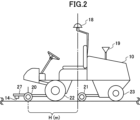
図2は芝刈り機1を側面から見た外観図である。図3は、本発明の1つの実施形態に係る芝刈り機の主要部の上面概念図である。上述した制御装置11、車速センサ12、方位角速度センサ13、駆動制御部17、及び走行駆動機構及び作業駆動機構は、芝刈り機1の機体10に内蔵されている。
<Lawnmower>
Fig. 2 is an external view of the
方位角速度センサ13は、芝刈り機1の挙動が正しく伝達される位置に設置される。GPSアンテナ18は、芝刈り機1の機体のほぼ中心部位、すなわち機体の長さ方向と幅方向それぞれのほぼ中心となるように備えられる。また、通信アンテナ19は、GPSアンテナ18の受信の障害にならないように芝刈り機1の機体の後方表面から突出するように取り付けられる。The azimuth velocity sensor 13 is installed in a position where the behavior of the
中央誘導線検出センサ15、左側誘導線検出センサ14、右側誘導線検出センサ16の3つの誘導線検出センサは、刈り刃(前方)20に取り付けられたステー27に取り付けられている。中央誘導線検出センサ15は、芝刈り機1の中央線C上で、芝刈り機1の旋回中心となる駆動輪22の車軸の中心に位置するピボットPvから後述の距離l[m]だけ離れた位置に配置され、左側誘導線検出センサ14と右側誘導線検出センサ16は、芝刈り機1の中央線Cに垂直で中央誘導線検出センサ15を通る直線上に、中央誘導線検出センサ15の左側と右側に、中央誘導線検出センサ15から後述の距離D[m]だけ離れた位置に配置されている。The three guideline detection sensors, the center
上述のように、芝刈り機1は、芝を刈るための一対の刈り刃(前方)20、刈り刃(後方)21を備えている。前方の刈り刃18は、走行方向と直交する方向の刈り幅W[m]のうち、左右端の芝を刈り取る。後方の刈り刃19は、刈り幅W[m]のうち、中央部の芝を刈り取る。この刈り幅W[m]が、芝刈り機1の1回の走行、作業で芝を刈りとることができる作業幅となる。As described above, the
<制御装置>
図1に戻り、制御装置11のGPS受信部101は、GPSアンテナ18で受信したGPSデータを制御情報生成部107へ出力する。送受信部102は、通信アンテナ19を介して、制御情報生成部107と基地局3との間の通信を可能にし、通信アンテナ19で受信した芝刈り機1の位置情報の誤差を補正するための補正情報を制御情報生成部107に出力する。制御情報生成部107は、GPSアンテナ18で受信したGPSデータと通信アンテナ19で受信した芝刈り機1の位置情報の誤差を補正するための補正情報に基づいて、芝刈り機1の現在位置を表す位置情報を生成する。また、送受信部102は、有線若しくは無線、又はLAN(Local Area Network)若しくは公衆通信回線を問わず任意のネットワークに接続されることができる。
<Control device>
Returning to FIG. 1 , the
車両情報受信部105は、車速センサ12及び方位角速度センサ13、及び/又はGPSデータによる位置の追跡から、芝刈り機1の走行速度、方位、挙動を表す検知情報を取得する。取得した情報がアナログデータの場合には、それらをデジタルデータに変換して出力する。その際、必要に応じて、方位角速度センサ13の出力からオフセット成分及びドリフト成分の除去処理等を施すデータ補正を行う。また、車両情報受信部105は、中央誘導線検出センサ15、左側誘導線検出センサ14、右側誘導線検出センサ16による磁界強度を取得する。車両情報受信部105の出力情報は、現在時刻データと関連付けて、記憶部108に記録される。The vehicle
駆動指令部106は、制御情報生成部107の出力情報(走行制御信号/作業制御信号)に基づいて、芝刈り機1を走行制御あるいは作業制御するために走行駆動機構あるいは作業駆動機構の制御内容を定めた情報を駆動制御部17へ出力する。駆動制御部17は、この情報をもとに、芝刈り機の走行駆動機構あるいは作業駆動機構を制御する。これにより、芝刈り機1による自動走行や自動走行による芝刈り作業が可能となる。Based on the output information (travel control signal/work control signal) of the control
記憶部108は、走行経路及び動作データや所定のコンピュータプログラム等を記録することができる。記憶部108は、ハードディスクや半導体メモリ等の任意の数の記憶部品から構成されるが、これらに限定されるものではない。The
リムーバブル記録媒体インタフェース部109には、CD-ROMやDVD等の光ディスク、USBメモリ、SDメモリカード等のリムーバブル記録媒体40が着脱自在に装着することができる。また、リムーバブル記録媒体インタフェース部109は、装着されたリムーバブル記録媒体40に記録されたデータを読み出したり、リムーバブル記録媒体40にデータを書き込んだりすることができる。リムーバブル記録媒体インタフェース部109は、例えばリムーバブル記録媒体40がCD-ROMやDVD等の光ディスクであれば専用のリーダ/ライタ等であり、USBメモリであればUSBポート等であり、SDメモリカードであればカードスロット等であるが、これらに限定されるものではない。
A
走行経路及び動作データが、記憶部108又はリムーバブル記録媒体インタフェース部109に装着されたリムーバブル記録媒体40に記録されている。動作データは、走行経路と関連付けられた、芝刈り機1の走行中あるいは停止中の刈り刃(前方)20、刈り刃(後方)21の昇降動作や回転の起動又は停止などを含む芝刈り作業に係る各種設定、芝刈り機1の速度や自動走行モードを含む。自動走行モードは、受信した測位信号に基づいて自動走行を行う測位モードと、電磁誘導線から発生する磁界を検出して前記電磁誘導線に沿って自動走行を行う電磁誘導モードを含む。制御情報生成部107は、測位モードである場合、その走行経路及び動作データとGPSデータや各種センサ11等より取得した現在位置とに基づいて、電磁誘導モードにおいては、中央誘導線検出センサ15、左側誘導線検出センサ14、右側誘導線検出センサ16により取得した磁界強度から算出した芝刈り機1の電磁誘導線Eからのずれに基づいて、走行制御信号及び作業制御信号を生成し、出力する。これにより自動走行による作業を可能にする。The travel route and operation data are recorded on the
<操舵制御システム>
次に、本発明の一実施形態に係る操舵制御システム及び方法について説明する。まず、その原理について説明する。図4は、電磁誘導線からの誘導線検出センサのずれと電磁誘導線と誘導線検出センサの位置関係の関係を示す図である。図5は、電磁誘導線上を自動走行する際の幾何学的関係を示す図である。図6から図9は、ピボットの軌跡と中央誘導線検出センサの軌跡の関係を示す図である。図10は、本発明の1つの実施形態に係る操舵制御処理の例のフローチャートである。
<Steering control system>
Next, a steering control system and method according to an embodiment of the present invention will be described. First, the principle will be described. FIG. 4 is a diagram showing the relationship between the deviation of the induction line detection sensor from the electromagnetic induction line and the positional relationship between the electromagnetic induction line and the induction line detection sensor. FIG. 5 is a diagram showing the geometric relationship when automatically traveling on the electromagnetic induction line. FIG. 6 to FIG. 9 are diagrams showing the relationship between the trajectory of the pivot and the trajectory of the center induction line detection sensor. FIG. 10 is a flowchart of an example of steering control processing according to one embodiment of the present invention.
操舵制御システム60は、制御装置11、中央誘導線検出センサ15、左側誘導線検出センサ14、右側誘導線検出センサ16を含む。The
図4は、芝刈り機1の進行方向に垂直な断面における、電磁誘導線からの誘導線検出センサのずれと電磁誘導線と誘導線検出センサの位置関係の関係を示す図である。図4を参照して、電磁誘導線Eから中央誘導線検出センサ15までの垂直方向の高さをh[m]、電磁誘導線Eからの中央誘導線検出センサ15の水平方向のずれ、すなわち電磁誘導線Eから中央誘導線検出センサ15までの水平方向の距離をd[m]、電磁誘導線を通る鉛直方向の直線と中央誘導線検出センサ15とのなす角度をθとすると、電磁誘導線Eから誘導線検出センサ15までの距離(磁力線半径)r[m]は、r=d/sinθ[m]となる。4 is a diagram showing the relationship between the offset of the induction line detection sensor from the electromagnetic induction line and the positional relationship between the electromagnetic induction line and the induction line detection sensor in a cross section perpendicular to the traveling direction of the
電磁誘導線Eから中央誘導線検出センサ15までの垂直方向の高さh[m]は一定であるとみなすと、d=r・sinθ[m]であるので、電磁誘導線Eから中央誘導線検出センサ15までの水平方向の距離dの値は電磁誘導線Eから中央誘導線検出センサ15までの距離r[m]に比例する。また、電磁誘導線Eから発する磁界の強さは、電磁誘導線Eから中央誘導線検出センサ15までの距離r[m]に反比例するため、r[m]が大きくなるほど、中央誘導線検出センサ15が検出する磁界は弱くなる。よって、閾値の強度以下の信号を検出しないようにすると、中央誘導線検出センサ15が検出可能な最大のr[m]の値を決定することができる。d[m]の値はr[m]の値に比例するので、中央誘導線検出センサ15が検出可能な最大のd[m]の値も決定することができる。この検出可能な最大の水平方向の距離d[m]を最大検出距離D[m]と呼ぶことにする。本実施形態においては、左側誘導線検出センサ14と右側誘導線検出センサ16の検出性能が同じであり、最大検出距離もD[m]とする。If the vertical height h [m] from the electromagnetic induction line E to the central induction
上述のように、中央誘導線検出センサ15は、芝刈り機1の中央線C上でピボットPvから距離l[m]だけ離れた位置に配置され、左側誘導線検出センサ14と右側誘導線検出センサ16は、芝刈り機1の中央線Cに垂直で中央誘導線検出センサ15を通る直線上に、中央誘導線検出センサ15の左側と右側に、中央誘導線検出センサ15から最大検出距離D[m]だけ離れた位置に配置されている。中央誘導線検出センサ15、左側誘導線検出センサ14、右側誘導線検出センサ16は、検出性能が同じであるから、このような配置により、中央誘導線検出センサ15の位置の電磁誘導線Eからのずれが検出できる。As described above, the center induction
制御装置11の制御情報生成部107は、車両情報受信部105により取得された、中央誘導線検出センサ15、左側誘導線検出センサ14、及び右側誘導線検出センサ16により取得された検出データである磁界強度に基づいて、芝刈り機1の電磁誘導線Eからのずれを算出する。具体的には、中央誘導線検出センサ15が磁界を検出せず、左側誘導線検出センサ14が磁界を検出した場合は、電磁誘導線Eが左側誘導線検出センサ14の左側に位置するようにずれていると判定することができる。また、中央誘導線検出センサ15が磁界を検出せず、右側誘導線検出センサ16が磁界を検出した場合は、電磁誘導線Eが右側誘導線検出センサ16の右側に位置するようにずれていると判定することができる。そして、中央誘導線検出センサ15が磁界を検出し、左側誘導線検出センサ14が磁界を検出した場合は、電磁誘導線Eが中央誘導線検出センサ15と左側誘導線検出センサ14の間に位置するようにずれていると判定することができる。また、中央誘導線検出センサ15が磁界を検出し、右側誘導線検出センサ16が磁界を検出した場合は、電磁誘導線Eが中央誘導線検出センサ15と右側誘導線検出センサ16の間に位置するようにずれていると判定することができる。The control
ただし、本実施形態においては、芝刈り機1(より厳密には、中央誘導線検出センサ15の位置)が電磁誘導線Eからそれ以上ずれた場合に芝刈り機1を停止させるずれ許容幅を最大検出距離D[m]と設定し、中央誘導線検出センサ15が磁界を検出しなかったときに、制御情報生成部107は、芝刈り機1を停止させる走行制御信号を生成し、芝刈り機1を停止させる。However, in this embodiment, the allowable deviation width for stopping the
なお、芝刈り機1の電磁誘導線Eからのずれの算出は、制御情報生成部107で算出する構成に限定されるものではなく、例えば、制御装置11の外部で算出し、算出されたずれを制御装置が受け取る構成等他の任意の適切な構成とすることができる。
The calculation of the deviation of the
また、中央誘導線検出センサ15を配置せず、左側誘導線検出センサ14と右側誘導線検出センサ16のみでも、左側誘導線検出センサ14の位置と右側誘導線検出センサ16の位置の中点の電磁誘導線Eからのずれは算出できるので、中央誘導線検出センサ15を配置しない構成としてもよい。
In addition, since the deviation from the electromagnetic induction line E of the midpoint between the position of the left induction
図5を参照して、芝刈り機1の操舵が行われたとき、芝刈り機1は、ピボット(制御点)Pvが、操舵輪の法線が交差する点(旋回中心O)を半径Rとする円弧の軌道を通るように移動する。ここで、左側誘導線検出センサ14と右側誘導線検出センサ16は、実際の制御には必要なものの、以下で考察する中央誘導線検出センサ15の芝刈り機1の前後方向の配置位置の範囲には影響しないため、図5では省略している。
Referring to Figure 5, when the
上述のように、制御情報生成部107は、中央誘導線検出センサ15、左側誘導線検出センサ14、右側誘導線検出センサ16により取得した磁界強度から算出した芝刈り機1の電磁誘導線Eからのずれに基づいて、走行制御信号を生成し、出力する。具体的には、制御情報生成部107は、制御サイクルt[秒]毎に、中央誘導線検出センサ15、左側誘導線検出センサ14、右側誘導線検出センサ16により取得した磁界強度から算出した芝刈り機1の電磁誘導線Eからのずれに基づいて、そのずれを打ち消すように芝刈り機1を旋回させ、又は芝刈り機1を直進させるような走行制御信号を生成し、出力する。出力された走行制御信号は駆動指令部106を介して駆動制御部17に送られ、駆動制御部17は受け取った走行制御信号に応じて、駆動輪22を制御し、操舵輪23を旋回させる。As described above, the control
なお、本実施形態においては、芝刈り機1は、電磁誘導線上を走行する際は、後進を行わないものとする。
In this embodiment, the
以上を前提に、芝刈り機1が電磁誘導線から逸脱することなく自動走行可能とするための中央誘導線検出センサ15の芝刈り機1の前後方向の配置位置の範囲について考察する。ここで、芝刈り機1は、最小旋回半径よりも小さい旋回半径で旋回することはできないので、走行経路は、最小旋回半径よりも小さい曲率半径のカーブを含んではならない。また、逆に、芝刈り機1は、最小旋回半径以上のカーブは走行することができる。よって、芝刈り機1が電磁誘導線から逸脱することなく自動走行可能であるか否かの限界の走行経路は、最小旋回半径を半径とする円弧を考えればよい。言い換えれば、最小旋回半径を半径とする円弧の電磁誘導線から逸脱することなく自動走行可能であるならば、最小旋回半径よりも小さい曲率半径のカーブを含まない走行経路は自動走行可能である。したがって、以下では、走行経路が最小旋回半径を半径とする円弧である場合について検討する。Based on the above, we will consider the range of the position of the center induction
(ピボットPv上にある場合)
まず、中央誘導線検出センサ15が、ピボットPv上にある場合を考えてみる。
(When on pivot Pv)
First, consider the case where the center guide
図6を参照して、中央誘導線検出センサ15が初期位置P0にある時は、制御情報生成部107はずれを検出しないので、操舵制御システム60は操舵を行わず、芝刈り機1は直進する。芝刈り機1が電磁誘導線E上を走行する時の速度をv[m/秒]としたとき、1制御サイクル後、すなわちt秒後のピボットPv及び中央誘導線検出センサ15は、初期位置P0からtv[m]だけ直進したP1の位置となる。6, when the center guiding
1制御サイクル後のこのタイミングで、制御情報生成部107は、電磁誘導線Eとのずれを検出するので、操舵制御システム60は、芝刈り機1を、最小旋回で電磁誘導線に近づくように、すなわち最小旋回半径で左側に旋回するように操舵する。しかしながら、この時、ピボットPvは、位置P1にあるので、図6から分かるように、芝刈り機1が最小旋回で旋回しても電磁誘導線Eに近づくことはできず、芝刈り機1は電磁誘導線Eに戻ることはできない。すなわち、旋回タイミングが遅すぎるので、芝刈り機1が電磁誘導線Eに戻ることができない。At this timing after one control cycle, the control
したがって、芝刈り機1の位置が電磁誘導線Eからずれた場合に、芝刈り機1が電磁誘導線Eに戻れるようにするためには、旋回タイミングを早める必要がある。そのためには、中央誘導線検出センサ15をピボットPvよりも前方側に配置する必要があるが、どのくらいの距離だけ前方に配置すれば芝刈り機1が電磁誘導線Eに戻ることができるようになるかについて以下検討する。Therefore, if the position of the
(ピボットPvから最も近い配置)
まず、ピボットPvから最も近い配置について検討する。図7を参照して、l=tv[m]、すなわち、中央誘導線検出センサ15が、芝刈り機1の中央線C上でピボットPvから距離tv[m]だけ離れて配置されている場合を考える。ピボットPvの初期位置をP2、中央誘導線検出センサ15の初期位置をP3とする。初期位置において、中央誘導線検出センサ15は、電磁誘導線E上の位置にあり、中央誘導線検出センサ15はずれを検出しないので、操舵制御システム60は操舵を行わず、芝刈り機1は直進する。1制御サイクル後、すなわちt秒後のピボットPv及び中央誘導線検出センサ15は、初期位置P2、P3からそれぞれtv[m]だけ、初期位置での芝刈り機1の中心線に沿って前方に直進したP3、P4の位置となる。
(The arrangement closest to the pivot Pv)
First, consider the arrangement closest to the pivot Pv. With reference to Fig. 7, consider the case where l = tv [m], that is, the center guide
1制御サイクル後のこのタイミングで、中央誘導線検出センサ15は、中央誘導線検出センサ15の位置が電磁誘導線Eから右側にずれていることを検出するので、操舵制御システム60は、芝刈り機1を、最小旋回で電磁誘導線に近づくように、すなわち最小旋回半径で左側に旋回するように操舵する。この時、ピボットPvは、位置P3にあるので、図7から分かるように、芝刈り機1は、最小旋回で旋回することにより、電磁誘導線Eから逸脱することなく、電磁誘導線E上を走行することができる。At this timing after one control cycle, the center induction
また、中央誘導線検出センサ15が、ピボットPvからtv[m]よりも小さい距離しか離れていなかった場合は、芝刈り機1は電磁誘導線Eに戻ることができないことが図6と図7の比較により理解することができる。
Furthermore, by comparing Figures 6 and 7, it can be understood that if the central induction
一方、図8を参照して、このような中央誘導線検出センサ15の配置において、初期位置において、中央誘導線検出センサ15が、芝刈り機1の中央線Cに垂直な方向に右側に距離D[m]だけ離れた場所にある場合を考える。ピボットPvの初期位置をP5、中央誘導線検出センサ15の初期位置をP6とする。初期位置において、中央誘導線検出センサ15は、中央誘導線検出センサ15の位置が電磁誘導線Eから右側にずれていることを検出するので、操舵制御システム60は、芝刈り機1を、最小旋回で電磁誘導線に近づくように、すなわち最小旋回半径で左側に旋回するように操舵する。1制御サイクル後、すなわちt秒後のピボットPvの位置は、最小旋回半径Rの円周上を距離tv[m]だけ進んだ位置P7となり、中央誘導線検出センサ15の位置は、位置P7から、位置P7における最小旋回半径Rの円周の接線方向に前方にtv[m]だけ離れた位置P8となる。位置P8において、中央誘導線検出センサ15の位置は、依然として電磁誘導線Eから右側にずれているので、制御情報生成部107は、中央誘導線検出センサ15の位置が電磁誘導線Eから右側にずれていることを検出するので、操舵制御システム60は、芝刈り機1を、再度、最小旋回で電磁誘導線に近づくように、すなわち最小旋回半径で左側に旋回するように操舵する。このような操舵を制御サイクル毎に繰り返すことにより、芝刈り機1は電磁誘導線Eに戻ることができる。
On the other hand, referring to FIG. 8, in such an arrangement of the center induction
以上から、芝刈り機1が電磁誘導線から逸脱することなく自動走行可能とするための、中央誘導線検出センサ15をピボットPvから最も近くに配置する場合の中央誘導線検出センサ15の位置は、中央誘導線検出センサ15が、芝刈り機1の中央線C上でピボットPvから距離tv[m]だけ離れた位置であることが分かる。
From the above, it can be seen that when the central induction
(ピボットPvから最も遠い配置)
次に、ピボットPvから最も遠い配置について検討する。図9を参照して、
![]()
![]()
Next, consider the arrangement furthest from the pivot Pv.
![]()
![]()
したがって、芝刈り機1が電磁誘導線からずれ許容幅D[m]より大きく逸脱することなく自動走行可能とするための、中央誘導線検出センサ15をピボットPvから最も遠くに配置する場合の中央誘導線検出センサ15の位置は、中央誘導線検出センサ15が、芝刈り機1の中央線C上でピボットPvから距離
![]()
![]()
以上から、l[m]をtv[m]以上、
![]()
![]()
以上の説明においては、中央誘導線検出センサ15、左側誘導線検出センサ14、及び右側誘導線検出センサ16の3つの誘導線検出センサによって、中央誘導線検出センサ15の位置の電磁誘導線Eからのずれが検出されていた。すなわち、中央誘導線検出センサ15、左側誘導線検出センサ14、及び右側誘導線検出センサ16の3つの誘導線検出センサによって検出される電磁誘導線Eからのずれの検出基準点は、中央誘導線検出センサ15の位置であった。よって、一般に、複数の誘導線検出センサが車両に取り付けられている場合、複数の誘導線検出センサによって検出される電磁誘導線Eからのずれの検出基準点が、上記の条件(tv[m]以上、
![]()
![]()
以上の原理を前提に、本発明の1つの実施形態に係る操舵制御方法の例について説明する。 Based on the above principles, we will explain an example of a steering control method according to one embodiment of the present invention.
車両情報受信部105は、中央誘導線検出センサ15、左側誘導線検出センサ14、及び右側誘導線検出センサ16から、各誘導線検出センサにより取得された検出データである磁界強度を取得する(S1)。The vehicle
制御情報生成部107は、制御サイクルt[秒]毎に、中央誘導線検出センサ15、左側誘導線検出センサ14、右側誘導線検出センサ16により取得した磁界強度から算出した芝刈り機1の電磁誘導線Eからのずれに基づいて、そのずれを打ち消すように芝刈り機1を旋回させ、又は芝刈り機1を直進させるような走行制御信号を生成し、出力する(S2)。出力された走行制御信号は駆動指令部106を介して駆動制御部17に送られ、駆動制御部17は受け取った走行制御信号に応じて、駆動輪22を制御し、操舵輪23を旋回させる(S3)。The control
本実施形態においては、誘導線検出センサの構成が、中央誘導線検出センサ15、左側誘導線検出センサ14、及び右側誘導線検出センサ16の3つの誘導線検出センサによって検出される電磁誘導線Eからのずれの検出基準点が、中央誘導線検出センサ15の位置である構成であり、前輪が駆動輪、後輪が操舵輪で、ピボットPvが駆動輪の車軸の中心に位置している車両であったが、このような車両に限定されるものでなく、ピボット(制御点)Pvが一意に決まる車両については、駆動方式(2輪駆動、3輪駆動、4輪駆動、等)や操舵方式(前輪操舵、後輪操舵)に依らず、複数の誘導線検出センサによって検出される電磁誘導線Eからのずれの検出基準点が、tv[m]以上かつ
![]()
![]()
本実施形態によれば、芝刈り機1が電磁誘導線から逸脱しないような制御を可能とすることができる。
According to this embodiment, it is possible to control the
上記実施形態においては、ずれ許容幅を中央誘導線検出センサの最大検出距離と設定したが、ずれ許容幅は、中央誘導線検出センサの最大検出距離でなくともよく、任意の適切な幅とすることができる。In the above embodiment, the allowable deviation width is set to the maximum detection distance of the central guide line detection sensor, but the allowable deviation width does not have to be the maximum detection distance of the central guide line detection sensor and can be any appropriate width.
操舵制御システムの一部機能は、別体のサーバ、基地局、タブレット型のコンピュータ等の、走行制御装置とは別体のものとして構成してもよい。Some functions of the steering control system may be configured as something separate from the driving control device, such as a separate server, base station, or tablet computer.
<自動走行システム>
次に、本発明の一実施形態に係る自動走行システムについて説明する。図11は、走行経路の一例を示す図である。図12は、本発明の1つの実施形態に係る自動走行システムの全体構成を示す図である。図13は、電磁誘導線に供給される交流電流と同期信号の一例を示す図である。図14は、隣接する閉ループ電磁誘導線の交流電流の位相が揃っている場合とずれている場合の電界強度の比較図である。
<Autonomous Driving System>
Next, an automatic driving system according to an embodiment of the present invention will be described. Fig. 11 is a diagram showing an example of a driving route. Fig. 12 is a diagram showing the overall configuration of an automatic driving system according to an embodiment of the present invention. Fig. 13 is a diagram showing an example of an AC current and a synchronization signal supplied to an electromagnetic induction line. Fig. 14 is a comparison diagram of electric field strength when the AC currents of adjacent closed loop electromagnetic induction lines are in phase with each other and when they are out of phase with each other.
図11は、走行経路の一例を示す図で、カート道CPからホールHに進入し、ホールHの芝刈りを行い、ホールHから再びカート道CPに戻り、カート道CPを進み、カート道CPから車庫Wに入る走行経路TPを示す図である。図12は、切り換えポイントSWP1付近から切り換えポイントSWP2付近までを拡大した、本発明の1つの実施形態に係る自動走行システムの全体構成を示す図である。 Figure 11 is a diagram showing an example of a driving route TP, which shows entering hole H from the cart path CP, mowing the grass of hole H, returning from hole H to the cart path CP again, proceeding along the cart path CP, and entering garage W from the cart path CP. Figure 12 is a diagram showing the overall configuration of an automated driving system according to one embodiment of the present invention, with an enlarged view from near switching point SWP1 to near switching point SWP2.
自動走行システム5は、第1の閉ループ電磁誘導線CL1と第2の閉ループ電磁誘導線CL2、第1の閉ループ電磁誘導線CL1、第2の閉ループ電磁誘導線CL2にそれぞれ対応する第1の電源装置51、第2の電源装置52を含む。第1の閉ループ電磁誘導線CL1と第2の閉ループ電磁誘導線CL2は隣接して配置されている。第1の閉ループ電磁誘導線CL1、第2の閉ループ電磁誘導線CL2には、対応する第1の電源装置51、第2の電源装置52がそれぞれ接続されている。The automated driving system 5 includes a first closed-loop electromagnetic induction line CL1 and a second closed-loop electromagnetic induction line CL2, and a first
第1の電源装置51は、第1の交流電流生成部511と同期信号生成部513を備える。また、第2の電源装置52は、第2の交流電流生成部521を備える。第1の交流電流生成部511と第2の交流電流生成部521は、同じ周波数の低周波の交流電流を生成する。本実施形態においては、例えば、図13に示されるような1.5kHzの矩形波交流電流を生成するが、これに限定されるものではなく、生成する交流電流の周波数は、他の任意の適切な低周波の周波数とすることができ、また、生成する交流電流の形状は、他の任意の適切な形状の交流電流とすることができる。The first
同期信号生成部513は、所定のタイミングで同期信号を生成する。同期信号生成部513で生成された同期信号は、第2の交流電流生成部521に供給され、第2の交流電流生成部521は、この同期信号に基づいて、所定のタイミングで、第1の交流電流生成部511によって生成される矩形波交流電流と同期した矩形波交流電流を生成する。このように、所定のタイミングで、第1の交流電流生成部511によって生成される矩形波交流電流と第2の交流電流生成部521によって生成される矩形波交流電流の同期が取られる。The synchronization
切り換えポイントSWP1から切り換えポイントSWP2までの走行経路TPは電磁誘導線上にある。具体的には、第1の閉ループ電磁誘導線CL1の第1の部分CL1Pと第2の閉ループ電磁誘導線CL2の第1の部分CL2Pが、走行経路TPを形成するように、互いに隣接して配置されている。第1の閉ループ電磁誘導線CL1の第1の部分CL1Pの両端と第2の閉ループ電磁誘導線CL2の第1の部分CL2Pの両端において、第1の閉ループ電磁誘導線CL1と第2の閉ループ電磁誘導線CL2は直角に折り曲げられ、折り曲げられた部分はカート道CP上で直線状となっている。このような構成とすることによって、第1の閉ループ電磁誘導線CL1と第2の閉ループ電磁誘導線CL2を接近して隣接させ、走行経路TP上の電磁誘導線間の間隔を小さくすることができ、また、芝刈り機1が、走行経路TPの方向ではなく、第1の閉ループ電磁誘導線CL1や第2の閉ループ電磁誘導線CL2の折れ曲がった方向に誘導されることを防止することができる。The travel path TP from the switching point SWP1 to the switching point SWP2 is on an electromagnetic induction line. Specifically, the first part CL1P of the first closed-loop electromagnetic induction line CL1 and the first part CL2P of the second closed-loop electromagnetic induction line CL2 are arranged adjacent to each other to form the travel path TP. At both ends of the first part CL1P of the first closed-loop electromagnetic induction line CL1 and both ends of the first part CL2P of the second closed-loop electromagnetic induction line CL2, the first closed-loop electromagnetic induction line CL1 and the second closed-loop electromagnetic induction line CL2 are bent at right angles, and the bent parts are linear on the cart path CP. By using such a configuration, the first closed loop electromagnetic induction line CL1 and the second closed loop electromagnetic induction line CL2 can be placed close to each other, reducing the distance between the electromagnetic induction lines on the travel path TP, and it is also possible to prevent the
このように、第1の閉ループ電磁誘導線CL1と第2の閉ループ電磁誘導線CL2が接近して隣接するようにされているので、第1の交流電流生成部511により生成される交流電流と第2の交流電流生成部521により生成される交流電流の位相がずれると、図14の右側の図に示されるように、隣接部付近で互いの、交流電流から発生する交番磁界が一部打ち消し合い、磁界強度が低下し、各誘導線検出センサが磁界を検出することができなくなり、走行を継続することが困難となる。したがって、第1の交流電流生成部511により生成される交流電流と第2の交流電流生成部521により生成される交流電流が高精度で位相のずれがほとんどないような場合でないときは、上述のように、第1の交流電流生成部511により生成される交流電流と第2の交流電流生成部521により生成される交流電流を同期信号によって、同期させることにより、隣接部付近での磁界強度が低下することを抑制して(図14の左側の図参照)、走行を継続すること可能とすることができる。In this way, since the first closed loop electromagnetic induction line CL1 and the second closed loop electromagnetic induction line CL2 are close to each other, if the phase of the AC current generated by the first AC
上記実施形態においては、走行経路TPを構成する、隣接する閉ループ電磁誘導線が2つであったが、走行経路TPを構成する、隣接する閉ループ電磁誘導線の数は2つに限定されるものではなく、任意の他の適切な数とすることができる。In the above embodiment, there were two adjacent closed-loop electromagnetic induction lines that constitute the travel path TP, but the number of adjacent closed-loop electromagnetic induction lines that constitute the travel path TP is not limited to two and can be any other appropriate number.
切り換えポイントSWP1、SWP2は、GPS衛星からの測位信号が良好に受信可能な位置に設定されており、上述の自動走行システム5において、芝刈り機1は、自動走行モードを測位モードとして、設定された走行経路に沿って自動走行し、切り替えポイントSWP1に達すると、測位モードから電磁誘導モードに自動走行モードを切り換えて、電磁誘導による自動走行を行う。そして、切り替えポイントSWP2に達すると、自動走行モードを電磁誘導モードから測位モードに切り換えて、測位(GPS)による自動走行を行い車庫Wに向かう。自動走行モードの切り換えは、記憶部108又はリムーバブル記録媒体インタフェース部109に装着されたリムーバブル記録媒体40に記録された走行経路及び動作データに基づいて制御情報生成部107によって生成される走行制御信号によって行われる。The switching points SWP1 and SWP2 are set at positions where the positioning signal from the GPS satellite can be received well, and in the above-mentioned automatic driving system 5, the
上記実施形態によれば、従来の長距離の電磁誘導線に電力を供給可能な容量の大きい電源が必要でないので、本実施形態の閉ループ電磁誘導線を数珠繋ぎすることによって長距離にわたって電磁誘導線による自動走行が可能となる。 According to the above embodiment, there is no need for a large-capacity power source capable of supplying power to conventional long-distance electromagnetic induction lines, so by stringing together the closed-loop electromagnetic induction lines of this embodiment, automatic driving using the electromagnetic induction line over long distances is possible.
GPSによる測位信号に基づいて自動走行を行う場合、GPS衛星からの測位信号が良好に受信できる必要がある。しかしながら、例えば、ゴルフコースにおいては、樹木が多く上空の見晴らしが悪い箇所も多い。芝刈り機が芝刈り作業を行うフェアウェイにおいては上空の視界を遮る樹木はごく一部に限られるものの、ホールとホールの間のカード道については、山間部を開拓した場所が多いため、作業ホール間のカート道は前述の樹木に加え、道幅が狭く高低差も大きい。芝刈り機に搭載されたジャイロセンサや車速センサ等から自己位置を推定し走行することもできるが、上述のような区間では路面の起伏や路面状況の変化に対応しきれず、自己位置を正確に求めることができないため、走行経路を自動走行することが難しい。本実施形態によれば、そのような測位モードでの自動走行が難しい区間を電磁誘導モードでの自動走行に切り換えて自動走行を行うことによって、GPS信号等の測位信号を受信できない、又は測位信号の受信強度が弱い経路が走行経路に含まれていても、全区間にわたって自動走行を可能とすることができる。When performing automatic driving based on GPS positioning signals, it is necessary to be able to receive positioning signals from GPS satellites well. However, for example, on golf courses, there are many trees and many places with poor views of the sky. Although only a few trees block the sky on the fairways where lawnmowers perform lawn mowing work, the cart paths between holes are often developed in mountainous areas, so in addition to the above-mentioned trees, the cart paths between work holes are narrow and have a large difference in elevation. It is possible to estimate the self-position using a gyro sensor or vehicle speed sensor mounted on the lawnmower and drive, but in the above-mentioned sections, it is difficult to respond to the undulations of the road surface and changes in the road surface conditions, and it is difficult to accurately determine the self-position, making it difficult to drive automatically along the driving route. According to this embodiment, by switching to automatic driving in electromagnetic induction mode in such sections where automatic driving in positioning mode is difficult, automatic driving can be made possible over the entire section even if the driving route includes a route where positioning signals such as GPS signals cannot be received or where the reception strength of the positioning signals is weak.
なお、上記の実施形態の方法を実現するコンピュータプログラムを記録した記録媒体を、制御装置10に対して供給してもよい。この場合、制御装置10のコンピュータが、記録媒体に記録されたコンピュータプログラムを読み取り、実行することによって、本発明の目的を達成することができる。したがって、記録媒体から読み取られたコンピュータプログラム自体が本発明の方法を実現するため、そのコンピュータプログラムが本発明を構成する。
A recording medium on which a computer program for implementing the method of the above embodiment is recorded may be supplied to the
上記の実施形態においては、本発明を芝刈り機に適用した例を説明したが、本発明は、散水機、散布機、施肥機、種まき機、土壌状態測定機、収穫機、耕耘機、耕土機、整地機をはじめとする農業機械、清掃機械、カート等の他の任意の適切な車両に適用可能である。In the above embodiment, an example of applying the present invention to a lawn mower has been described, but the present invention can be applied to any other suitable vehicle, such as agricultural machinery including watering machines, sprayers, fertilizer applicators, seeders, soil condition measuring machines, harvesters, tillers, cultivators, and soil levelers, cleaning machines, carts, etc.
上記の実施形態においては、測位モードで用いる測位信号はGPSデータであったが、測位モードで用いる測位信号はこれに限定されるものではなく、車両の種類に応じて、GPSデータ、無線LANのアクセスポイントから発信されるビーコン信号、BLEビーコン信号、インパルス方式UWB(IR-UWB)信号、IMES(Indoor Messaging System)信号等他の適切な任意の測位信号、又はそれらの全部又は一部の組み合わせとすることができる。In the above embodiment, the positioning signal used in the positioning mode was GPS data, but the positioning signal used in the positioning mode is not limited to this and can be any other appropriate positioning signal, such as GPS data, a beacon signal transmitted from a wireless LAN access point, a BLE beacon signal, an impulse-type UWB (IR-UWB) signal, an IMES (Indoor Messaging System) signal, or a combination of all or part of these, depending on the type of vehicle.
以上、本発明について、例示のためにいくつかの実施形態に関して説明してきたが、本発明はこれに限定されるものでなく、本発明の範囲及び精神から逸脱することなく、形態及び詳細について、様々な変形及び修正を行うことができることは、当業者に明らかであろう。Although the present invention has been described above with reference to several embodiments for illustrative purposes, it will be apparent to those skilled in the art that the present invention is not limited thereto, and that various changes and modifications in form and details can be made without departing from the scope and spirit of the present invention.
1・・・芝刈り機
10・・・本体
11・・・制御装置
12・・・車速センサ
13・・・方位角速度センサ
14・・・左側誘導線検出センサ
15・・・中央誘導線検出センサ
16・・・右側誘導線検出センサ
17・・・駆動制御部
18・・・GPSアンテナ
19・・・通信アンテナ
20・・・刈り刃(前方)
21・・・刈り刃(後方)
22・・・駆動輪
23・・・操舵輪
24・・・操作入力部
25・・・表示部
26・・・音声出力部
27・・・ステー
101・・・GPS受信部
102・・・送受信部
105・・・車両情報受信部
106・・・駆動指令部
107・・・制御情報生成部
108・・・記憶部
109・・・リムーバブル記録媒体インタフェース部
112・・・主制御部
3・・・基地局
31・・・GPS受信装置
32・・・送受信装置
35・・・GPSアンテナ
36・・・通信アンテナ
40・・・リムーバブル記録媒体
5・・・自動走行システム
51・・・第1の電源装置
511・・・第1の交流電流生成部
513・・・同期信号生成部
52・・・第2の電源装置
521・・・第2の交流電流生成部
60・・・操舵制御システム
Pv・・・ピボット
R・・・最小旋回半径
C・・・芝刈り機の中心線
D・・・最大検出距離、ずれ許容幅
E・・・電磁誘導線
CP・・・カート道
H・・・ホール
W・・・車庫
TP・・・走行経路
SWP1、SWP2・・・切り換えポイント
CL1・・・第1の閉ループ電磁誘導線
CL1P・・・第1の閉ループ電磁誘導線CL1の第1の部分
CL2・・・第2の閉ループ電磁誘導線
CL2P・・・第2の閉ループ電磁誘導線CL1の第1の部分
1: Lawnmower 10: Main body 11: Control device 12: Vehicle speed sensor 13: Azimuth angle speed sensor 14: Left guideline detection sensor 15: Center guideline detection sensor 16: Right guideline detection sensor 17: Drive control unit 18: GPS antenna 19: Communication antenna 20: Cutting blade (front)
21...Cutting blade (rear)
22... Driving
Claims (17)
前記車両に取り付けられた複数の誘導線検出センサと、
制御サイクル毎に、前記複数の誘導線検出センサにより取得された検出データから算出した前記車両の前記電磁誘導線からのずれに基づいて、そのずれを打ち消すように前記車両を旋回させ、又は前記車両を直進させるような走行制御信号を生成し、出力する制御装置と、
を備え、
前記複数の誘導線検出センサのずれ検出基準点が、前記車両の旋回中心となるピボットから水平方向の距離l[m]だけ前方側に離れた位置に配置されており、
前記距離l[m]は、前記制御サイクルをt[秒]、前記車両が前記電磁誘導線上を走行する時の速度をv[m/秒]、前記ずれ検出基準点の前記電磁誘導線からの水平方向のずれ許容幅をD[m]、前記車両の最小旋回半径をR[m]としたとき、tv[m]以上かつ
A plurality of guide wire detection sensors mounted on the vehicle;
a control device that generates and outputs a travel control signal for each control cycle, based on a deviation of the vehicle from the electromagnetic induction line calculated from detection data acquired by the plurality of induction line detection sensors, so as to turn the vehicle or to move the vehicle straight so as to cancel the deviation;
Equipped with
the deviation detection reference points of the plurality of guiding line detection sensors are disposed at positions spaced forward by a horizontal distance 1 [m] from a pivot that is the turning center of the vehicle,
The distance l [m] is equal to or greater than tv [m], where t [sec] is the control cycle, v [m/sec] is the speed at which the vehicle travels on the electromagnetic induction line, D [m] is the allowable horizontal deviation width of the deviation detection reference point from the electromagnetic induction line, and R [m] is the minimum turning radius of the vehicle.
前記ずれ検出基準点が前記車両の中央線上に配置され、中央誘導線検出センサが前記すれ検出基準点に配置され、前記左側誘導線検出センサ及び前記右側誘導線検出センサが、前記車両の中央線に垂直で前記中央誘導線検出センサを通る直線上に、前記中央誘導線検出センサの左側と右側にそれぞれ配置されている請求項1に記載の操舵制御システム。 The plurality of guiding line detection sensors include only a set of a center guiding line detection sensor, a left guiding line detection sensor, and a right guiding line detection sensor;
2. The steering control system according to claim 1, wherein the deviation detection reference point is disposed on a center line of the vehicle, a center guide line detection sensor is disposed at the deviation detection reference point, and the left guide line detection sensor and the right guide line detection sensor are disposed on a straight line perpendicular to the center line of the vehicle and passing through the center guide line detection sensor, on the left and right sides of the center guide line detection sensor, respectively.
前記前輪が、駆動輪であり、前記後輪が、操舵輪であり、
前記前輪の車軸の中心が前記ピボットである請求項1~3のいずれか1項に記載の操舵制御システム。 The vehicle has front and rear wheels,
The front wheels are driving wheels and the rear wheels are steering wheels,
4. A steering control system according to claim 1, wherein the center of the axle of the front wheels is the pivot.
前記車両には、複数の誘導線検出センサが取り付けられており、
制御サイクル毎に、前記複数の誘導線検出センサにより取得された検出データから算出した前記車両の前記電磁誘導線からのずれに基づいて、そのずれを打ち消すように前記車両を旋回させ、又は前記車両を直進させるような走行制御信号を生成し、出力し、
前記複数の誘導線検出センサのずれ検出基準点が、前記車両の旋回中心となるピボットから水平方向の距離l[m]だけ前方側に離れた位置に配置されており、
前記距離l[m]は、前記制御サイクルをt[秒]、前記車両が前記電磁誘導線上を走行する時の速度をv[m/秒]、前記ずれ検出基準点の前記電磁誘導線からの水平方向のずれ許容幅をD[m]、前記車両の最小旋回半径をR[m]としたとき、tv[m]以上かつ
A plurality of guide wire detection sensors are attached to the vehicle,
generating and outputting a travel control signal for each control cycle based on a deviation of the vehicle from the electromagnetic induction line calculated from the detection data acquired by the plurality of induction line detection sensors, so as to turn the vehicle or move the vehicle in a straight line so as to cancel the deviation;
the deviation detection reference points of the plurality of guiding line detection sensors are disposed at positions spaced forward by a horizontal distance 1 [m] from a pivot that is the turning center of the vehicle,
The distance l [m] is equal to or greater than tv [m], where t [sec] is the control cycle, v [m/sec] is the speed at which the vehicle travels on the electromagnetic induction line, D [m] is the allowable horizontal deviation width of the deviation detection reference point from the electromagnetic induction line, and R [m] is the minimum turning radius of the vehicle.
前記ずれ検出基準点が前記車両の中央線上に配置され、中央誘導線検出センサが前記すれ検出基準点に配置され、前記左側誘導線検出センサ及び前記右側誘導線検出センサが、前記車両の中央線に垂直で前記中央誘導線検出センサを通る直線上に、前記中央誘導線検出センサの左側と右側にそれぞれ配置されている請求項7に記載の操舵制御方法。 The plurality of guiding line detection sensors include only a set of a center guiding line detection sensor, a left guiding line detection sensor, and a right guiding line detection sensor;
8. The steering control method according to claim 7, wherein the deviation detection reference point is disposed on a center line of the vehicle, a center guide line detection sensor is disposed at the deviation detection reference point, and the left guide line detection sensor and the right guide line detection sensor are disposed on a straight line perpendicular to the center line of the vehicle and passing through the center guide line detection sensor, on the left and right sides of the center guide line detection sensor, respectively.
前記前輪が、駆動輪であり、前記後輪が、操舵輪であり、
前記前輪の車軸の中心が前記ピボットである請求項7~9のいずれか1項に記載の操舵制御方法。 The vehicle has front and rear wheels,
The front wheels are driving wheels and the rear wheels are steering wheels,
The steering control method according to any one of claims 7 to 9, wherein the center of the axle of the front wheels is the pivot.
互いに交差せず互いに隣接して配置された、複数の閉ループ電磁誘導線と、
前記複数の閉ループ電磁誘導線にそれぞれ対応する電源装置と、
を含み、
前記複数の閉ループ電磁誘導線の各々の一部が、走行経路を形成するように、互いに隣接して配置され、
前記複数の閉ループ電磁誘導線毎に対応する電源装置がそれぞれ接続され、前記電源装置から前記複数の閉ループ電磁誘導線に同じ周波数の低周波の交流電流が供給される、
自動走行システム。 An automatic driving system for a vehicle that can automatically travel along an electromagnetic induction line by detecting a magnetic field generated from the electromagnetic induction line,
A plurality of closed-loop electromagnetic induction lines arranged adjacent to each other without crossing each other ;
a power supply device corresponding to each of the plurality of closed loop electromagnetic induction lines;
Including,
A portion of each of the plurality of closed-loop electromagnetic induction lines is disposed adjacent to one another to form a travel path;
A power supply device is connected to each of the plurality of closed-loop electromagnetic induction lines, and a low-frequency AC current having the same frequency is supplied from the power supply device to the plurality of closed-loop electromagnetic induction lines.
Autonomous driving system.
前記電磁誘導線が敷設されていない経路は、前記測位モードで自動走行が行われる請求項13又は14に記載の自動走行システム。 The vehicle has, as an automatic driving mode, a positioning mode in which automatic driving is performed based on a received positioning signal, and an electromagnetic induction mode in which a magnetic field generated from an electromagnetic induction line is detected and automatic driving is performed along the electromagnetic induction line,
The automatic driving system according to claim 13 or 14, wherein automatic driving is performed in the positioning mode on a route on which the electromagnetic induction line is not installed.
Applications Claiming Priority (1)
| Application Number | Priority Date | Filing Date | Title |
|---|---|---|---|
| PCT/JP2021/039882 WO2023073882A1 (en) | 2021-10-28 | 2021-10-28 | Vehicle, system for steering control, method, program, recording medium storing program, and autonomous travelling system |
Publications (3)
| Publication Number | Publication Date |
|---|---|
| JPWO2023073882A1 JPWO2023073882A1 (en) | 2023-05-04 |
| JPWO2023073882A5 JPWO2023073882A5 (en) | 2024-02-15 |
| JP7470878B2 true JP7470878B2 (en) | 2024-04-18 |
Family
ID=86157515
Family Applications (1)
| Application Number | Title | Priority Date | Filing Date |
|---|---|---|---|
| JP2023555994A Active JP7470878B2 (en) | 2021-10-28 | 2021-10-28 | Vehicle, system, method, program for steering control, recording medium having the program recorded thereon, and automatic driving system |
Country Status (2)
| Country | Link |
|---|---|
| JP (1) | JP7470878B2 (en) |
| WO (1) | WO2023073882A1 (en) |
Citations (3)
| Publication number | Priority date | Publication date | Assignee | Title |
|---|---|---|---|---|
| JP3192406B2 (en) | 1999-02-22 | 2001-07-30 | シャープ株式会社 | CCTV equipment |
| JP5345056B2 (en) | 2006-06-30 | 2013-11-20 | コンステリウム ロールド プロダクツ−レイヴンズウッド,エルエルシー | Heat-treatable high-strength aluminum alloy |
| JP2020140424A (en) | 2019-02-28 | 2020-09-03 | 日本車輌製造株式会社 | Transport vehicle and steering control program for transport vehicle |
Family Cites Families (4)
| Publication number | Priority date | Publication date | Assignee | Title |
|---|---|---|---|---|
| JPS62175813A (en) * | 1986-01-30 | 1987-08-01 | Komatsu Ltd | Method for guiding curved route of unmanned vehicle |
| JP2987858B2 (en) * | 1989-12-22 | 1999-12-06 | 日本電気株式会社 | Travel control method for carrier vehicles |
| JPH05345056A (en) * | 1992-06-17 | 1993-12-27 | Kubota Corp | Golf cart |
| JP4036290B2 (en) * | 2002-08-28 | 2008-01-23 | 日本輸送機株式会社 | Unmanned transport system and unmanned transport method |
-
2021
- 2021-10-28 JP JP2023555994A patent/JP7470878B2/en active Active
- 2021-10-28 WO PCT/JP2021/039882 patent/WO2023073882A1/en active Application Filing
Patent Citations (3)
| Publication number | Priority date | Publication date | Assignee | Title |
|---|---|---|---|---|
| JP3192406B2 (en) | 1999-02-22 | 2001-07-30 | シャープ株式会社 | CCTV equipment |
| JP5345056B2 (en) | 2006-06-30 | 2013-11-20 | コンステリウム ロールド プロダクツ−レイヴンズウッド,エルエルシー | Heat-treatable high-strength aluminum alloy |
| JP2020140424A (en) | 2019-02-28 | 2020-09-03 | 日本車輌製造株式会社 | Transport vehicle and steering control program for transport vehicle |
Also Published As
| Publication number | Publication date |
|---|---|
| JPWO2023073882A1 (en) | 2023-05-04 |
| WO2023073882A1 (en) | 2023-05-04 |
Similar Documents
| Publication | Publication Date | Title |
|---|---|---|
| RU2728604C2 (en) | System and method of lane tracking for off-road vehicle and off-road vehicle | |
| US11696525B2 (en) | Automatic travel work machine, automatic travel grass mower, grass mower, and grass mower automatic travel system | |
| JP3467136B2 (en) | Travel control device for autonomous vehicles | |
| US8954216B2 (en) | Work machine and components thereof | |
| EP3403155B1 (en) | Self-propellered robotic tool navigation | |
| US7689356B2 (en) | Method and apparatus for creating curved swath patterns for farm machinery | |
| EP2376869B1 (en) | Method and system for determining a position of a vehicle | |
| US8275506B1 (en) | Boundary sensor | |
| EP3589111B1 (en) | Improved reduction of wheel tracks for robotic lawnmower | |
| US9821847B2 (en) | Method for guiding an off-road vehicle along a curved path | |
| JP7470878B2 (en) | Vehicle, system, method, program for steering control, recording medium having the program recorded thereon, and automatic driving system | |
| WO2021244594A1 (en) | Automatic lawn mower and path planning method, system, and device thereof | |
| JPH09120313A (en) | Guidance controller for working vehicle | |
| JP3236487B2 (en) | Work vehicle guidance control device | |
| CN113448327A (en) | Operation control method of automatic walking equipment and automatic walking equipment | |
| CN110933317B (en) | Intelligent steering method and system for vehicle-mounted camera | |
| JPH09149706A (en) | Traveling control device for autonomous running vehicle | |
| SE2050629A1 (en) | Method of providing a position estimate of a robotic tool, a robotic tool, and a robotic tool system | |
| JP3564201B2 (en) | Self-position detection device for autonomous traveling work vehicles | |
| JP6342764B2 (en) | Autonomous vehicle | |
| JPH09305229A (en) | Moving body automatic operation device | |
| US20220312669A1 (en) | Work machine system and work machine | |
| JP6456083B2 (en) | Autonomous vehicle | |
| JP6345558B2 (en) | Autonomous vehicle | |
| CN113515113A (en) | Operation control method of automatic walking equipment and automatic walking equipment |
Legal Events
| Date | Code | Title | Description |
|---|---|---|---|
| A521 | Request for written amendment filed |
Free format text: JAPANESE INTERMEDIATE CODE: A523 Effective date: 20231215 |
|
| A621 | Written request for application examination |
Free format text: JAPANESE INTERMEDIATE CODE: A621 Effective date: 20231215 |
|
| A871 | Explanation of circumstances concerning accelerated examination |
Free format text: JAPANESE INTERMEDIATE CODE: A871 Effective date: 20231215 |
|
| A01 | Written decision to grant a patent or to grant a registration (utility model) |
Free format text: JAPANESE INTERMEDIATE CODE: A01 Effective date: 20240307 |
|
| A61 | First payment of annual fees (during grant procedure) |
Free format text: JAPANESE INTERMEDIATE CODE: A61 Effective date: 20240408 |