WO2023068331A1 - フィルムモールド - Google Patents
フィルムモールド Download PDFInfo
- Publication number
- WO2023068331A1 WO2023068331A1 PCT/JP2022/039114 JP2022039114W WO2023068331A1 WO 2023068331 A1 WO2023068331 A1 WO 2023068331A1 JP 2022039114 W JP2022039114 W JP 2022039114W WO 2023068331 A1 WO2023068331 A1 WO 2023068331A1
- Authority
- WO
- WIPO (PCT)
- Prior art keywords
- film
- resin
- mold
- curable resin
- resin material
- Prior art date
- Legal status (The legal status is an assumption and is not a legal conclusion. Google has not performed a legal analysis and makes no representation as to the accuracy of the status listed.)
- Ceased
Links
Images

Classifications
-
- B—PERFORMING OPERATIONS; TRANSPORTING
- B29—WORKING OF PLASTICS; WORKING OF SUBSTANCES IN A PLASTIC STATE IN GENERAL
- B29C—SHAPING OR JOINING OF PLASTICS; SHAPING OF MATERIAL IN A PLASTIC STATE, NOT OTHERWISE PROVIDED FOR; AFTER-TREATMENT OF THE SHAPED PRODUCTS, e.g. REPAIRING
- B29C33/00—Moulds or cores; Details thereof or accessories therefor
- B29C33/42—Moulds or cores; Details thereof or accessories therefor characterised by the shape of the moulding surface, e.g. ribs or grooves
- B29C33/424—Moulding surfaces provided with means for marking or patterning
-
- B—PERFORMING OPERATIONS; TRANSPORTING
- B29—WORKING OF PLASTICS; WORKING OF SUBSTANCES IN A PLASTIC STATE IN GENERAL
- B29C—SHAPING OR JOINING OF PLASTICS; SHAPING OF MATERIAL IN A PLASTIC STATE, NOT OTHERWISE PROVIDED FOR; AFTER-TREATMENT OF THE SHAPED PRODUCTS, e.g. REPAIRING
- B29C33/00—Moulds or cores; Details thereof or accessories therefor
- B29C33/38—Moulds or cores; Details thereof or accessories therefor characterised by the material or the manufacturing process
-
- B—PERFORMING OPERATIONS; TRANSPORTING
- B29—WORKING OF PLASTICS; WORKING OF SUBSTANCES IN A PLASTIC STATE IN GENERAL
- B29C—SHAPING OR JOINING OF PLASTICS; SHAPING OF MATERIAL IN A PLASTIC STATE, NOT OTHERWISE PROVIDED FOR; AFTER-TREATMENT OF THE SHAPED PRODUCTS, e.g. REPAIRING
- B29C33/00—Moulds or cores; Details thereof or accessories therefor
- B29C33/38—Moulds or cores; Details thereof or accessories therefor characterised by the material or the manufacturing process
- B29C33/3842—Manufacturing moulds, e.g. shaping the mould surface by machining
- B29C33/3857—Manufacturing moulds, e.g. shaping the mould surface by machining by making impressions of one or more parts of models, e.g. shaped articles and including possible subsequent assembly of the parts
- B29C33/3878—Manufacturing moulds, e.g. shaping the mould surface by machining by making impressions of one or more parts of models, e.g. shaped articles and including possible subsequent assembly of the parts used as masters for making successive impressions
-
- B—PERFORMING OPERATIONS; TRANSPORTING
- B29—WORKING OF PLASTICS; WORKING OF SUBSTANCES IN A PLASTIC STATE IN GENERAL
- B29C—SHAPING OR JOINING OF PLASTICS; SHAPING OF MATERIAL IN A PLASTIC STATE, NOT OTHERWISE PROVIDED FOR; AFTER-TREATMENT OF THE SHAPED PRODUCTS, e.g. REPAIRING
- B29C37/00—Component parts, details, accessories or auxiliary operations, not covered by group B29C33/00 or B29C35/00
- B29C37/0025—Applying surface layers, e.g. coatings, decorative layers, printed layers, to articles during shaping, e.g. in-mould printing
-
- B—PERFORMING OPERATIONS; TRANSPORTING
- B29—WORKING OF PLASTICS; WORKING OF SUBSTANCES IN A PLASTIC STATE IN GENERAL
- B29C—SHAPING OR JOINING OF PLASTICS; SHAPING OF MATERIAL IN A PLASTIC STATE, NOT OTHERWISE PROVIDED FOR; AFTER-TREATMENT OF THE SHAPED PRODUCTS, e.g. REPAIRING
- B29C48/00—Extrusion moulding, i.e. expressing the moulding material through a die or nozzle which imparts the desired form; Apparatus therefor
- B29C48/001—Combinations of extrusion moulding with other shaping operations
- B29C48/002—Combinations of extrusion moulding with other shaping operations combined with surface shaping
-
- B—PERFORMING OPERATIONS; TRANSPORTING
- B29—WORKING OF PLASTICS; WORKING OF SUBSTANCES IN A PLASTIC STATE IN GENERAL
- B29C—SHAPING OR JOINING OF PLASTICS; SHAPING OF MATERIAL IN A PLASTIC STATE, NOT OTHERWISE PROVIDED FOR; AFTER-TREATMENT OF THE SHAPED PRODUCTS, e.g. REPAIRING
- B29C48/00—Extrusion moulding, i.e. expressing the moulding material through a die or nozzle which imparts the desired form; Apparatus therefor
- B29C48/02—Small extruding apparatus, e.g. handheld, toy or laboratory extruders
-
- B—PERFORMING OPERATIONS; TRANSPORTING
- B29—WORKING OF PLASTICS; WORKING OF SUBSTANCES IN A PLASTIC STATE IN GENERAL
- B29C—SHAPING OR JOINING OF PLASTICS; SHAPING OF MATERIAL IN A PLASTIC STATE, NOT OTHERWISE PROVIDED FOR; AFTER-TREATMENT OF THE SHAPED PRODUCTS, e.g. REPAIRING
- B29C59/00—Surface shaping of articles, e.g. embossing; Apparatus therefor
- B29C59/02—Surface shaping of articles, e.g. embossing; Apparatus therefor by mechanical means, e.g. pressing
-
- B—PERFORMING OPERATIONS; TRANSPORTING
- B29—WORKING OF PLASTICS; WORKING OF SUBSTANCES IN A PLASTIC STATE IN GENERAL
- B29D—PRODUCING PARTICULAR ARTICLES FROM PLASTICS OR FROM SUBSTANCES IN A PLASTIC STATE
- B29D7/00—Producing flat articles, e.g. films or sheets
- B29D7/01—Films or sheets
Definitions
- the present invention relates to a film mold for transferring an uneven shape to the surface of a curable resin material.
- Liquid crystal display devices are often used as display devices for various electronic devices. In recent years, such electronic devices have become more and more compact, and liquid crystal display devices are also required to be smaller and lighter.
- Such liquid crystal display devices mainly use optical functional sheets that utilize the effects of reflection, refraction, scattering, etc., and sheets that combine these.
- an optical functional sheet a shaped film obtained by imparting a predetermined irregular shape to the surface of a resin film is known.
- Such a shaped film is usually produced by press molding using a molding plate having a desired uneven shape, or by injection molding.
- Patent Document 1 proposes a method using a film mold (release film for mold molding).
- a film mold release film for mold molding
- a silicone compound, a fluorine compound, or the like is used as a material that forms the uneven shape of the film mold. compounds are used.
- Patent Document 2 a technique using poly-4-methylpentene-1 as a release sheet of thermoplastic resin is disclosed in a specific example thereof.
- Patent Document 2 only discloses an aspect in which poly-4-methylpentene-1 is used as a release sheet of a thermoplastic resin, and an index for selecting an appropriate material was unknown. .
- An object of the present invention is to provide a film mold that exhibits good wettability and releasability with respect to a curable resin material, and that can satisfactorily form uneven shapes on the surface of the curable resin material.
- the present inventors have found a film mold made of a resin film having an uneven surface for transferring an uneven shape to the surface of a curable resin material.
- the inventors have found that the above object can be achieved by controlling the surface free energy S E and the free volume S V of the uneven surface measured by the positron annihilation method within a predetermined range, and have completed the present invention. .
- a film mold made of a resin film having an uneven surface for transferring an uneven shape to the surface of a curable resin material The surface free energy S E [unit: mN/m] of the uneven surface and the free volume S V [unit: nm 3 ] of the uneven surface measured by the positron annihilation method are expressed by the following formulas (1) to ( A film mold is provided that satisfies 3). S E >35.7 (1) S V >0 (2) S E ⁇ 296.77 ⁇ S V +77.371 (3)
- the film mold of the present invention is preferably a long film obtained by continuously or intermittently imparting unevenness to the surface of a resin film formed by melt extrusion.
- the film mold of the present invention is a long film obtained by continuously or intermittently applying an ultraviolet curable resin to the surface of a base film and curing the resin to impart an uneven shape to the surface.
- the film mold of the present invention preferably has an average thickness of 10 to 200 ⁇ m. Further, according to the present invention, the step of bringing the film mold described in any of the above into contact with the layer made of the curable resin material formed on the substrate; and curing a curable resin material.
- the present invention it is possible to provide a film mold that exhibits good wettability and releasability with respect to a curable resin material, and that can satisfactorily form uneven shapes on the surface of the curable resin material.
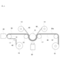
- FIG. 1 is a diagram showing an example of a shaped film manufacturing apparatus using a film mold according to an embodiment of the present invention.
- FIG. 2 is a graph showing the relationship between the surface free energy S E and the free volume S V of resin films according to Examples and Comparative Examples.
- FIG. 1 is a diagram showing an example of a shaped film manufacturing apparatus using a film mold according to an embodiment of the present invention.
- the manufacturing apparatus shown in FIG. 1 is mainly illustrated as an example, but the present invention is not particularly limited to the embodiment shown in FIG.
- the base film 40 is continuously fed out from the base feed roll 10, and the base film 40 passes through the guide roll 11, and the surface of the base film 40 is processed by the T die 20. Then, a curable resin material layer 50 is formed on the surface by applying a curable resin material. The thickness of the curable resin material layer 50 is controlled by adjusting the clearance formed by the T-die 20 and the nip roll 12 and the delivery speed.
- the manufacturing apparatus shown in FIG. 1 is configured so that the film mold 60 is continuously delivered from the film mold delivery roll 13 . Then, the base film 40 on which the curable resin material layer 50 is formed and the film mold 60 are overlaid by the laminate roll 15 and the upstream backup roll 16 .
- the film mold 60 has a predetermined uneven shape on the side facing the curable resin material layer 50 , and the surface having the predetermined uneven shape is in contact with the curable resin material layer 50 . In this state, the base film 40, the curable resin material layer 50, and the film mold 60 are layered in this order to form a laminate.
- the curable resin material layer 50 is formed by irradiating the laminate in which the base film 40, the curable resin material layer 50, and the film mold 60 are laminated in this order with ultraviolet rays from the ultraviolet irradiation device 30.
- the curable resin material is cured in a state in which the predetermined irregularities formed on the surface of the film mold 60 are transferred, thereby forming the cured resin layer 50a having the desired irregularities on the surface.
- the film mold 60 is separated from the base film 40 including the cured resin layer 50a by passing between the laminate roll 15 and the downstream backup roll 17. 60 is taken up by the take-up roll 14 for film molding, and the base film 40 having the cured resin layer 50 a is taken up by the take-up roll 19 for base material via the guide roll 18 .
- the base film 40 including the cured resin layer 50a is continuously produced as described above. Then, the substrate film 40 having the cured resin layer 50a manufactured in this manner has a desired uneven shape on its surface by transferring the predetermined uneven shape formed on the film mold 60. Therefore, it is used as a shaping film, and is suitably used for various optical applications as an optical functional sheet that utilizes the effects of reflection, refraction, scattering, and the like.
- the film mold 60 is a resin film having an uneven surface, and the surface free energy S E [unit: mN/m] of the uneven surface and the freedom of the uneven surface measured by the positron annihilation method A resin film whose volume S V [unit: nm 3 ] satisfies the following formulas (1) to (3) is used.
- S E >35.7 (1)
- S V >0 (2)
- the film mold 60 may have an uneven shape in which the surface free energy S E and the free volume S V satisfy the above formulas (1) to (3) on at least one surface. uneven shape may be formed.
- the film mold 60 is pressed against the substrate film 40 on which the curable resin material layer 50 is formed, and the uneven shape of the film mold 60 is pressed against the surface of the curable resin material layer 50. While maintaining this state, the curable resin material forming the curable resin material layer 50 is cured by ultraviolet irradiation, thereby transferring the uneven shape of the film mold 60 to the cured resin layer. 50a can be formed.
- the surface free energy S E of the uneven surface and the free volume S V of the uneven surface satisfy the above formulas (1) to (3).
- the film mold 60 can exhibit good wettability with respect to the curable resin material forming the curable resin material layer 50 and can exhibit excellent releasability. It is possible to satisfactorily form the cured resin layer 50a having an uneven shape.
- the present inventors have studied the resin material that constitutes the film mold 60, and have obtained the following findings. That is, if a resin material having excellent releasability is used as the resin material forming the film mold 60, the wettability with respect to the curable resin material forming the curable resin material layer 50 deteriorates, resulting in uneven wetting. , air bubbles tend to be caught between the film mold 60 and the curable resin material layer 50, and such air bubbles become a drawback, and there is a problem that the cured resin layer 50a having the desired irregular shape cannot be formed.
- the surface free energy S E of the uneven surface and the free volume S V of the uneven surface should be in a range that satisfies the above formulas (1) to (3).
- the film mold 60 can exhibit good wettability with respect to the curable resin material constituting the curable resin material layer 50 and can exhibit excellent peelability, and thereby, It has been found that the cured resin layer 50a having the desired uneven shape can be formed satisfactorily.
- the surface free energy S E of the uneven surface and the free volume S V of the uneven surface may satisfy the above formulas (1) to (3). It is preferable to satisfy any one or all of the following formulas (4) to (6) from the viewpoint that wettability and peelability can be more highly balanced with respect to the constituent curable resin material. , or any one or all of the following formulas (7) to (9) are more preferably satisfied. 40 ⁇ S E ⁇ 60 (4) 0.06 ⁇ SV ⁇ 0.1 (5) ⁇ 296.77 ⁇ S V +67 ⁇ S E ⁇ 296.77 ⁇ S V +77 (6)
- the surface free energy S E of the uneven surface is less than 35.7 mN/m, wettability with respect to the curable resin material forming the curable resin material layer 50 will deteriorate, and the film mold 60 and the curable resin material will not be wettable. Air bubbles tend to be caught between the layer 50 and the cured resin layer 50a having a desired uneven shape cannot be formed.
- the free volume SV of the uneven surface is preferably 0.06 nm 3 or more, the permeability of the curable resin material forming the curable resin material layer 50 to the film mold 60 can be increased, thereby improving the molding. It is possible to make the adhesion required for the above sufficient. In addition, from the viewpoint of further improving the releasability, it is more preferable that 0.06 ⁇ S V ⁇ 0.08.
- the surface free energy S E of the uneven surface of the film mold 60 is obtained by measuring the contact angles of water, diiodomethane, and ethylene glycol on the uneven surface of the film mold 60, and using the measured contact angle data, Kitazaki and Hata's analysis. It can be calculated by theory.
- the free volume SV of the uneven surface can be obtained by measuring the uneven surface of the film mold 60 by the positron annihilation method.
- the positron annihilation method is a type of positron annihilation lifetime measurement method, in which the time from the incidence of positrons to a sample until they annihilate is measured, and the free volume of vacancies is calculated from the annihilation lifetime.
- the average thickness of the film mold 60 is not particularly limited, it is preferably 10-200 ⁇ m, more preferably 20-100 ⁇ m, still more preferably 30-60 ⁇ m. By setting the average thickness of the film mold 60 within the above range, the cured resin layer 50a having the desired uneven shape can be manufactured with higher productivity.
- Concavo-convex shapes that can be produced by film molding include, for example, a continuous or intermittent shape having a height of 1 to 30 ⁇ m, an aspect ratio of 0.5 to 1.0, and an interval of 0 to 20 times the height. can.
- the method for producing the film mold 60 is not particularly limited, but for example, a resin film is obtained by a melt extrusion method, the obtained resin film is heated, and a shaping roll having a predetermined irregular shape formed on the surface is pressed against it.
- a resin film is obtained by a melt extrusion method, the obtained resin film is heated, and a shaping roll having a predetermined irregular shape formed on the surface is pressed against it.
- a method of obtaining a long film by continuously or intermittently forming an uneven shape on the surface is not particularly limited. is mentioned.
- an ultraviolet curable resin is continuously or intermittently applied to the surface of the resin film that serves as the base film, and the resin is cured to obtain a film using the ultraviolet curable resin. It is also possible to adopt a method of forming an uneven shape, thereby obtaining a long film having an uneven shape on the surface.
- the resin material that constitutes the resin film that forms the film mold 60 is not particularly limited, but is preferably a thermoplastic resin.
- Acrylic resin such as polymethyl methacrylate (PMMA), carbonate resin such as polycarbonate (PC), amide resin such as nylon 6, cyclic olefin resin (COP), ethylene-vinyl alcohol copolymer (EVOH), polyphenylene sulfide (PPS) etc.
- PMMA polymethyl methacrylate
- PC polycarbonate
- amide resin such as nylon 6, cyclic olefin resin
- EVOH ethylene-vinyl alcohol copolymer
- PPS polyphenylene sulfide
- the ultraviolet curable resin may be a radical curable acrylic monomer, an acrylic oligomer such as urethane acrylate, epoxy acrylate, or polyester acrylate, or an undesired resin. Saturated polyesters, or cationic curable epoxy resins, oxetane resins, vinyl ethers, and the like can be used.
- a base film used at this time the thing which consists of above-described resin materials, etc. are mentioned.
- the method for setting the surface free energy S E of the uneven surface of the film mold 60 and the free volume S V of the uneven surface of the film mold 60 within the above ranges is not particularly limited, but for example, the resin material constituting the resin film forming the film mold 60 a method of modifying the surface by corona treatment, a method of adjusting the wettability with a surface modifier, a method of adjusting the free volume by adding inorganic fine particles, a method of adjusting the free volume by adding inorganic fine particles, and if the resin material is a crystalline resin , a method of adjusting the degree of crystallinity, and the like.
- the degree of crystallinity is increased, thereby increasing the density of the molecular arrangement.
- the free volume SV can be reduced without changing the surface free energy SE .
- the curable resin material constituting the curable resin material layer 50 is not particularly limited, and may be either a thermosetting resin or an ultraviolet curable resin. Wire resins are preferred.
- the UV curable ray resin the same resin as that exemplified in the case of forming the uneven shape of the film mold with the UV curable resin can be used, and is not particularly limited, but from the viewpoint of imparting optical functionality, it has good transparency.
- Acrylic resin is preferable, and when a curable resin material is applied to the surface of the T-die 20 in the manufacturing apparatus shown in FIG.
- thermosetting resin used as the curable resin material forming the curable resin material layer 50
- a heating device such as a heater is used instead of the ultraviolet irradiation device 30 shown in FIG. It may be set in such a manner that it is cured by
- the curable resin material constituting the curable resin material layer 50 preferably has a viscosity (B-type viscosity) at a temperature of 25° C. before curing from the viewpoint of better transfer of the uneven shape by the film mold 60. is 10 to 600 cps, more preferably 20 to 100 cps, still more preferably 20 to 70 cps, and the curable resin material preferably has a viscosity within this range when substantially free of solvent. Further, when a solvent-free ultraviolet curable resin is used, the viscosity in a state in which the solvent is not substantially contained is in this range, so that when applying with the T die 20 in the manufacturing apparatus shown in FIG. It can also be excellent in coatability.
- the average thickness of the curable resin material layer 50 before curing and the average thickness of the cured resin layer 50a after curing are not particularly limited, and may be appropriately selected according to the characteristics and application of the resulting shaped film. It is preferably 1 to 100 ⁇ m, more preferably 5 to 20 ⁇ m.
- the base film 40 is not particularly limited.
- a light-transmitting resin film is preferable, and examples of resin materials constituting such a resin film include acrylic resins, polycarbonate resins, acrylic-modified polycarbonate resins, cyclic olefin resins, and the like. A resin etc. are mentioned.
- the average thickness of the base film 40 is not particularly limited, and may be appropriately selected according to the properties and applications of the resulting shaped film, preferably 10 to 200 ⁇ m, more preferably 20 to 40 ⁇ m.
- the film mold 60 a resin film is used in which the surface free energy S E of the uneven surface and the free volume S V of the uneven surface satisfy the above formulas (1) to (3).
- the cured resin layer having the desired uneven shape on the surface. 50a can be well formed.
- ⁇ Free volume SV > A resin film was adhered to a silicon wafer of 15 mm ⁇ 15 mm, and a sample vacuum degassed at 25° C. was used to measure the positron annihilation lifetime under the following conditions.
- a testing machine (trade name “Tensilon universal material testing machine RTC-1210A”, manufactured by ORIENTEC Co., Ltd., with respect to the adhesion surface between the cured acrylic resin film as the cured resin layer 50a and the resin film as the film mold 60, 90 ° peel A test was carried out to measure the 90° peel strength [unit: N/25mm].When used as a film mold, from the viewpoint that it can be peeled off well, if the 90° peel strength is 2N/25mm or less, it is considered to pass. bottom.
- an acrylic resin (trade name “PAK-02”, Toyo Gosei Co., Ltd. was applied to the surface of a polyester film with an easy-adhesion layer (trade name “Cosmoshine A4300”, manufactured by Toyobo Co., Ltd., thickness 38 ⁇ m) as the base material 40. company, B type viscosity at 25° C.: 70 cps or less) was applied using a bar coater to form an acrylic resin layer having a thickness of 10 ⁇ m as the curable resin material layer 50 .
- Examples 2 to 10> The surface free energy S E and the free volume S V were measured in the same manner as in Example 1, except that the resin films shown in Table 1 were used as the film mold 60, and the same as in Example 1. Then, a laminate of a polyester film with an easy-adhesion layer as the substrate 40, a cured acrylic resin film as the cured resin layer 50a, and a resin film as the film mold 60 was obtained. The presence or absence of was measured. Table 1 shows the results.
- Example 2 Biaxially stretched polybutylene terephthalate resin film (trade name “BOBLET BO-PBT”, manufactured by Kohjin Film & Chemicals, thickness 25 ⁇ m)
- Example 3 PBT (3): A polybutylene terephthalate resin (trade name “Gelanex 700FP”, manufactured by Polyplastics Co., Ltd.) was formed into a film with a thickness of 40 ⁇ m at 250 ° C. by a melt extrusion method.
- Example 4 (Nylon 6): Nylon 6 film (trade name “Harden N1100” manufactured by Toyobo Co., Ltd., thickness 20 ⁇ m))
- Example 5 Polyphenylene sulfide resin film (trade name “Torelina”, manufactured by Toray Industries, Inc., thickness 100 ⁇ m)
- Example 6 (EVOH): Ethylene-vinyl alcohol copolymer resin film (trade name “EVAL”, manufactured by Kuraray Co., Ltd., thickness 20 ⁇ m)
- Example 7 (COP): cycloolefin resin film (trade name "ZEONOR”, manufactured by Nippon Zeon Co., Ltd., thickness 130 ⁇ m)
- Comparative Examples 1 to 9 are as follows.
- PP (1) Unstretched polypropylene film (trade name “RXC22”, manufactured by Mitsui Chemicals Tocello, thickness 20 ⁇ m)
- PP (2) A non-stretched polypropylene film obtained by forming a polypropylene resin (homo-PP) into a film with a thickness of 200 ⁇ m by a melt extrusion method
- PP (3) Polypropylene (trade name “ SunAllomer”, manufactured by SunAllomer) at 260°C by a melt extrusion method to form a film with a thickness of 100 ⁇ m.
- Comparative Example 4 Low-density polyethylene film (thickness: 100 ⁇ m)
- Comparative Example 5 PTFE: Polytetrafluoroethylene film (trade name “Naflon”, manufactured by Nichias, thickness 100 ⁇ m)
- TPX Polymethylpentene resin film (trade name “Opulan X-44B”, manufactured by Mitsui Chemicals, Inc., thickness 20 ⁇ m)
- Comparative Example 7 PET (2)
- PET polyethylene terephthalate resin film (trade name “Cosmo Shine A4100” manufactured by Toyobo Co., Ltd., thickness 38 ⁇ m)
- the surface free energy S E and the free volume S V of the resin film used as the film mold 60 are represented by formulas (1) to (3) (formula (1): S E >35.7, Formula (2): S V > 0, Formula (3): S E ⁇ 296.77 ⁇ S V +77.371), for the cured acrylic resin as the cured resin layer 50a
- the peel strength was low, the peelability was excellent, the generation of air bubbles was suppressed, and good wettability was exhibited (Examples 1 to 10).
- the spectrum of the interface between the cured resin layer and the film mold was measured by Raman spectroscopy, and the penetration depth of the cured resin was obtained from the intensity ratio of the specific peaks. The penetration depth was 0 ⁇ m.
- the depth of penetration of the cured resin into the resin film of Comparative Example 9 was 4 ⁇ m, and there was a tendency that the deeper the penetration depth, the stronger the peel strength.
- Table 1 shows the measurement results of the penetration depth.
- “N.D.” indicates that peak separation was difficult and measurement of penetration depth was difficult.
- the specific measurement method was as follows. That is, the cross section of the laminate of the resin film that serves as the base material 40, the cured acrylic resin film that serves as the cured resin layer 50a, and the resin film that serves as the film mold 60 is measured using a laser Raman spectrophotometer. Multiple points were measured in the thickness direction across the interface between the layer 50 a and the film mold 60 .
- the measurement peaks less affected by the orientation state of the resin film are selected as the cured resin layer 50a.
- the ratio of the intensity P1 of the measurement peak that does not overlap with the measurement peak derived from the cured acrylic resin film and has the highest intensity to the intensity P2 of the measurement peak that has the highest intensity among the other measurement peaks. P1/P2 was calculated.
- the position where the ratio P1/P2 is stably small is regarded as the cured resin layer 50a, and the position where the ratio P1/P2 is stably large is regarded as the film mold 60. is changed, and this range is regarded as a region in which the cured acrylic resin as the cured resin layer 50a permeates the resin film to be the film mold 60, and the width of this range is calculated as the permeation depth.
- FIG. 2 graphically shows the relationship between the surface free energy S E and the free volume S V of the resin films according to each example and comparative example.
Landscapes
- Engineering & Computer Science (AREA)
- Mechanical Engineering (AREA)
- Manufacturing & Machinery (AREA)
- Health & Medical Sciences (AREA)
- Clinical Laboratory Science (AREA)
- Laminated Bodies (AREA)
- Moulds For Moulding Plastics Or The Like (AREA)
- Shaping Of Tube Ends By Bending Or Straightening (AREA)
- Liquid Crystal (AREA)
Abstract
硬化性の樹脂材料の表面に凹凸形状を転写するための、凹凸表面を備える樹脂フィルムからなるフィルムモールドであって、前記凹凸表面の表面自由エネルギーSE[単位:mN/m]と、陽電子消滅法で測定される、前記凹凸表面の自由体積SV[単位:nm3]とが、下記式(1)~(3)を満たすフィルムモールドを提供する。 SE>35.7 (1) SV>0 (2) SE<-296.77×SV+77.371 (3)
Description
本発明は、硬化性の樹脂材料の表面に凹凸形状を転写するための、フィルムモールドに関する。
各種電子機器の表示装置として、液晶表示装置が多く用いられている。このような電子機器においては、近年、小型化がますます進んでおり、液晶表示装置にも、小型化・軽量化が求められている。
このような液晶表示装置には、主として反射、屈折、散乱等の作用を活用した光機能シートやこれらを複合したシートが用いられている。このような光機能シートとしては、樹脂フィルム表面に、所定の凹凸形状を付与してなる賦形フィルムが知られている。このような賦形フィルムは、通常、所望の凹凸形状をもった型付け板を用いてプレス成形するか、射出成形することによって製造される。
樹脂フィルム表面に、所定の凹凸形状を付与する別の方法として、たとえば、特許文献1では、フィルムモールド(モールド成形用離型フィルム)を用いる方法が提案されている。この特許文献1の技術においては、凹凸形状の形成の対象となるフィルム材料に対する離型性の観点より、フィルムモールドの、凹凸形状を構成する材料として、シリコーン化合物やフッ素化合物などの離型性の化合物が使用されている。一方、特許文献2の技術においては、その具体的な実施例において、熱可塑性樹脂の離型性シートとして、ポリ4-メチルペンテン-1を用いた技術が開示されている。
しかしながら、上記特許文献1に記載の技術では、凹凸形状の形成の対象となるフィルム材料に対する、フィルムモールドの剥離性が十分であるものの、濡れ性が十分でなく、そのため、凹凸形状の転写性が必ずしも十分ではないという課題があり、特に、凹凸形状の形成の対象となるフィルム材料として、硬化性の樹脂材料を用いた場合に、このような問題が顕著であった。特許文献2の技術では、熱可塑性樹脂の離型性シートとしてポリ4-メチルペンテン-1を使用した態様が開示されているのみであり、適切な材料を選択するための指標は不明であった。
本発明は、硬化性の樹脂材料に対し、良好な濡れ性および剥離性を示し、硬化性の樹脂材料の表面に、凹凸形状を良好に形成可能なフィルムモールドを提供することを目的とする。
本発明者等は、上記目的を達成すべく鋭意検討を行った結果、硬化性の樹脂材料の表面に凹凸形状を転写するための、凹凸表面を備える樹脂フィルムからなるフィルムモールドについて、凹凸表面の表面自由エネルギーSEと、陽電子消滅法で測定される、前記凹凸表面の自由体積SVとを所定の範囲に制御することにより、上記目的を達成できることを見出し、本発明を完成させるに至った。
すなわち、本発明によれば、硬化性の樹脂材料の表面に凹凸形状を転写するための、凹凸表面を備える樹脂フィルムからなるフィルムモールドであって、
前記凹凸表面の表面自由エネルギーSE[単位:mN/m]と、陽電子消滅法で測定される、前記凹凸表面の自由体積SV[単位:nm3]とが、下記式(1)~(3)を満たすフィルムモールドが提供される。
SE>35.7 (1)
SV>0 (2)
SE<-296.77×SV+77.371 (3)
前記凹凸表面の表面自由エネルギーSE[単位:mN/m]と、陽電子消滅法で測定される、前記凹凸表面の自由体積SV[単位:nm3]とが、下記式(1)~(3)を満たすフィルムモールドが提供される。
SE>35.7 (1)
SV>0 (2)
SE<-296.77×SV+77.371 (3)
本発明のフィルムモールドは、溶融押出法により形成される樹脂フィルムに対し、連続的または断続的に表面に凹凸形状が付与されてなる長尺状のフィルムであることが好ましい。
あるいは、本発明のフィルムモールドは、基材フィルムの表面に対し、連続的または断続的に、紫外線硬化樹脂を塗布し、硬化することによって、表面に凹凸形状が付与されてなる長尺状のフィルムであることが好ましい。
本発明のフィルムモールドは、平均厚みが、10~200μmであることが好ましい。
また、本発明によれば、基材上に形成された硬化性樹脂材料からなる層に、上記のいずれかに記載のフィルムモールドを接触させる工程と、前記フィルムモールドを接触させた状態で、前記硬化性樹脂材料を硬化させる工程とを備えるパターン化硬化樹脂層の製造方法が提供される。
あるいは、本発明のフィルムモールドは、基材フィルムの表面に対し、連続的または断続的に、紫外線硬化樹脂を塗布し、硬化することによって、表面に凹凸形状が付与されてなる長尺状のフィルムであることが好ましい。
本発明のフィルムモールドは、平均厚みが、10~200μmであることが好ましい。
また、本発明によれば、基材上に形成された硬化性樹脂材料からなる層に、上記のいずれかに記載のフィルムモールドを接触させる工程と、前記フィルムモールドを接触させた状態で、前記硬化性樹脂材料を硬化させる工程とを備えるパターン化硬化樹脂層の製造方法が提供される。
本発明によれば、硬化性の樹脂材料に対し、良好な濡れ性および剥離性を示し、硬化性の樹脂材料の表面に、凹凸形状を良好に形成可能なフィルムモールドを提供することができる。
図1は、本発明の実施形態に係るフィルムモールドを用いた、賦形フィルムの製造装置の一例を示す図である。なお、以下においては、主として、図1に示す製造装置を例示して、説明を行うが本発明は、図1に示す態様に特に限定されるものではない。
図1に示す製造装置においては、まず、基材用繰り出しロール10から、基材フィルム40が連続的に繰り出され、基材フィルム40は、ガイドロール11を経て、Tダイ20にて、その表面に、硬化性樹脂材料が塗布されることにより、その表面に、硬化性樹脂材料層50が形成される。なお、硬化性樹脂材料層50は、Tダイ20と、ニップロール12とにより形成されるクリアランスや、繰り出し速度を調整することによって、その厚みが制御される。
また、図1に示す製造装置においては、フィルムモールド用繰り出しロール13から、フィルムモールド60が連続的に繰り出されるように構成されている。そして、硬化性樹脂材料層50が形成された基材フィルム40と、フィルムモールド60とは、ラミネートロール15と、上流側バックアップロール16とにより重ね合わされる。ここで、フィルムモールド60は、硬化性樹脂材料層50と対向する面側に、所定の凹凸形状を有しており、所定の凹凸形状を有する面が、硬化性樹脂材料層50と接触するような状態で、基材フィルム40、硬化性樹脂材料層50、およびフィルムモールド60の順で重ね合わされた積層体とされる。
そして、基材フィルム40、硬化性樹脂材料層50、およびフィルムモールド60の順で重ね合わされた積層体に対し、紫外線照射装置30により紫外線を照射することで、硬化性樹脂材料層50を構成する硬化性樹脂材料が、フィルムモールド60表面に形成された所定の凹凸形状が転写された状態にて、硬化し、これにより、表面に所望の凹凸形状を備えた硬化樹脂層50aとなる。次いで、紫外線照射による硬化反応を経た後、ラミネートロール15と、下流側バックアップロール17との間を通り、硬化樹脂層50aを備える基材フィルム40から、フィルムモールド60が剥離された後、フィルムモールド60については、フィルムモールド用巻き取りロール14に巻き取られ、硬化樹脂層50aを備える基材フィルム40は、ガイドロール18を介して、基材用巻き取りロール19により巻き取られる。
図1に示す製造装置によれば、以上のようにして、硬化樹脂層50aを備える基材フィルム40が連続的に生産される。そして、このようにして、製造される硬化樹脂層50aを備える基材フィルム40は、フィルムモールド60に形成せれた所定の凹凸形状が転写されることにより、その表面に所望の凹凸形状を備えるものであるため、賦形フィルムとして用いられ、たとえば、反射、屈折、散乱等の作用を活用した光機能シートとして、各種光学用途に好適に用いられるものである。
本実施形態においては、フィルムモールド60として、凹凸表面を備える樹脂フィルムであって、凹凸表面の表面自由エネルギーSE[単位:mN/m]と、陽電子消滅法で測定される、凹凸表面の自由体積SV[単位:nm3]とが、下記式(1)~(3)を満たす樹脂フィルムを用いる。
SE>35.7 (1)
SV>0 (2)
SE<-296.77×SV+77.371 (3)
SE>35.7 (1)
SV>0 (2)
SE<-296.77×SV+77.371 (3)
フィルムモールド60は、少なくとも一方の表面に、表面自由エネルギーSEおよび自由体積SVが上記式(1)~(3)を満たす凹凸形状が形成されていればよく、両方の面に、このような凹凸形状が形成されていてもよい。
そして、本実施形態においては、フィルムモールド60を、硬化性樹脂材料層50が形成された基材フィルム40に対し、フィルムモールド60の凹凸形状が、硬化性樹脂材料層50の表面に押し付けられた状態で積層し、この状態を保ったまま、紫外線照射により、硬化性樹脂材料層50を構成する硬化性樹脂材料を硬化することで、フィルムモールド60の凹凸形状が転写されてなる、硬化樹脂層50aを形成できるものである。
本実施形態によれば、フィルムモールド60として、凹凸表面の表面自由エネルギーSEと、凹凸表面の自由体積SVとが、上記式(1)~(3)を満たす樹脂フィルムを用いることで、フィルムモールド60を、硬化性樹脂材料層50を構成する硬化性樹脂材料に対し、良好な濡れ性を示し、かつ、優れた剥離性を示すものとすることができるものであり、これにより、所望の凹凸形状を有する硬化樹脂層50aを良好に形成できるものである。
特に、フィルムモールド60を構成する樹脂材料について、本発明者等が検討を行ったところ、以下のような知見を得たものである。すなわち、フィルムモールド60を構成する樹脂材料として、離型性に優れた樹脂材料を使用すると、硬化性樹脂材料層50を構成する硬化性樹脂材料に対する濡れ性が悪化し、均一に濡れないこととなり、フィルムモールド60と硬化性樹脂材料層50との間に、気泡を噛み込みやすくなり、このような気泡が欠点となり、所望の凹凸形状を有する硬化樹脂層50aが形成できないという問題があった。一方で、硬化性樹脂材料層50を構成する硬化性樹脂材料に対する濡れ性に優れた樹脂材料を選択すると、硬化性樹脂材料に対する密着力が強くなり過ぎてしまい、離型性が悪化してしまい、剥離時に、硬化樹脂層50aの形状が破損してしまう等の不具合が発生してしまうという問題があった。
これに対し、本発明者等がさらなる検討を行ったところ、凹凸表面の表面自由エネルギーSEと、凹凸表面の自由体積SVとを上記式(1)~(3)を満たす範囲とすることにより、フィルムモールド60を、硬化性樹脂材料層50を構成する硬化性樹脂材料に対し、良好な濡れ性を示し、かつ、優れた剥離性を示すものとすることができること、そして、これにより、所望の凹凸形状を有する硬化樹脂層50aを良好に形成できることを見出したものである。
フィルムモールド60において、凹凸表面の表面自由エネルギーSEと、凹凸表面の自由体積SVとは、上記式(1)~(3)を満たすものであればよいが、硬化性樹脂材料層50を構成する硬化性樹脂材料に対する、濡れ性と剥離性とをより高度にバランスさせることができるという点より、下記式(4)~(6)のいずれか一つ、あるいは、全てを満たすことが好ましく、下記式(7)~(9)のいずれか一つ、あるいは、全てを満たすことがより好ましい。
40≦SE≦60 (4)
0.06≦SV≦0.1 (5)
-296.77×SV+67≦SE≦-296.77×SV+77 (6)
40≦SE≦60 (4)
0.06≦SV≦0.1 (5)
-296.77×SV+67≦SE≦-296.77×SV+77 (6)
凹凸表面の表面自由エネルギーSEが、35.7mN/m未満であると、硬化性樹脂材料層50を構成する硬化性樹脂材料に対する濡れ性が悪化してしまい、フィルムモールド60と硬化性樹脂材料層50との間に気泡を噛み込みやすくなり、所望の凹凸形状を有する硬化樹脂層50aが形成できなくなってしまう。
凹凸表面の自由体積SVが、好ましくは0.06nm3以上であると、硬化性樹脂材料層50を構成する硬化性樹脂材料のフィルムモールド60に対する浸透性を高めることができ、これにより、成形に必要となる密着性を充分なものとすることができる。なお、剥離性をより高めるという観点からは、0.06≦SV≦0.08であることがより好ましい。
また、SE≧-296.77×SV+77.371であると、硬化性樹脂材料に対する密着力が強くなり過ぎてしまい、剥離性が悪化してしまい、剥離時に、硬化樹脂層50aの形状が破損してしまい、所望の凹凸形状を有する硬化樹脂層50aが形成できなくなってしまう。
なお、フィルムモールド60の凹凸表面の表面自由エネルギーSEは、フィルムモールド60の凹凸表面の、水、ジヨードメタン、エチレングリコールの接触角を測定し、測定された接触角データから、北崎・畑の解析理論によって算出することができる。また、凹凸表面の自由体積SVは、フィルムモールド60の凹凸表面について、陽電子消滅法による測定を行うことで求めることができる。陽電子消滅法とは、陽電子消滅寿命測定法の一種であり、陽電子が試料に入射してから消滅するまでの時間を測定し、その消滅寿命から空孔の自由体積を算出する方法である。
フィルムモールド60の平均厚みは、特に限定されないが、好ましくは10~200μmであり、より好ましくは20~100μm、さらに好ましくは30~60μmである。フィルムモールド60の平均厚みを上記範囲とすることにより、所望の凹凸形状を有する硬化樹脂層50aを、より高い生産性にて製造することができる。フィルムモールドにより製造できる凹凸形状としては、例えば、高さ1~30μm、アスペクト比0.5~1.0で、間隔が高さの0~20倍の連続的もしくは断続的な形状を挙げることができる。
フィルムモールド60の製造方法としては、特に限定されないが、たとえば、溶融押出法により樹脂フィルムを得て、得られた樹脂フィルムを加熱し、所定の凹凸形状が表面に形成された賦形ロールを押し付けることにより、連続的または断続的に、その表面に凹凸形状を形成することで、長尺状のフィルムとして得る方法などが挙げられる。なお、所定の凹凸形状が表面に形成された賦形ロールに押し付ける際における、樹脂フィルムの加熱温度としては、特に限定されないが、樹脂フィルムを構成する樹脂材料のガラス転移温度以上に加熱する方法などが挙げられる。
あるいは、フィルムモールド60の製造方法としては、基材フィルムとなる樹脂フィルムに対し、その表面に、連続的または断続的に、紫外線硬化樹脂を塗布し、これを硬化することによって、紫外線硬化樹脂による凹凸形状を形成し、これにより、表面に凹凸形状が付与されてなる長尺状のフィルムとして得る方法を採用することもできる。
フィルムモールド60を形成する樹脂フィルムを構成する樹脂材料としては、特に限定されないが、熱可塑性の樹脂であることが好ましく、たとえば、ポリエチレンテレフタレート(PET)、ポリブチレンテレフタレート(PBT)などのポリエステル樹脂、ポリメチルメタクリレート(PMMA)などのアクリル樹脂、ポリカーボネート(PC)などのカーボネート樹脂、ナイロン6などのアミド樹脂、環状オレフィン樹脂(COP)、エチレン-ビニルアルコール共重合体(EVOH)、ポリフェニレンサルファイド(PPS)などが挙げられる。また、これらは2種以上を積層して用いてもよいし、あるいは、2種以上を混合して用いてもよい。
また、紫外線硬化樹脂による凹凸形状を形成する方法を採用する場合には、紫外線硬化樹脂として、ラジカル硬化系であるアクリル系モノマーや、ウレタンアクリレート、エポキシアクリレート、ポリエステルアクリレートのようなアクリル系オリゴマー、不飽和ポリエステル、もしくはカチオン硬化系であるエポキシ樹脂、オキセタン樹脂、ビニルエーテルなどを用いることができる。なお、この際に用いる基材フィルムとしては、上記した樹脂材料からなるものなどが挙げられる。
フィルムモールド60の凹凸表面の表面自由エネルギーSE、および凹凸表面の自由体積SVを上記範囲とする方法としては、特に限定されないが、たとえば、フィルムモールド60を形成する樹脂フィルムを構成する樹脂材料を選択する方法や、コロナ処理によって表面を改質する方法、表面改質剤によって濡れ性を調整する方法、無機微粒子添加によって自由体積を調整する方法、樹脂材料が結晶性の樹脂である場合に、結晶化度を調整する方法などが挙げられる。特に、ポリエチレンテレフタレートなどの結晶性の樹脂の場合には、加熱条件やフィルム化する際の延伸条件などを制御することで、結晶化度を高くすることで、分子配列の密な部分を多くすることにより、表面自由エネルギーSEを変化せずに、自由体積SVを小さくすることができる。
また、硬化性樹脂材料層50を構成する硬化性樹脂材料としては、特に限定されず、熱硬化性樹脂、紫外線硬化線樹脂のいずれでもよいが、生産効率に優れているという観点より、紫外線硬化線樹脂が好ましい。紫外線硬化線樹脂としては、フィルムモールドの凹凸形状を紫外線硬化樹脂で形成する場合として例示したものと同様の樹脂を用いることができ、特に限定されないが、光機能性付与の観点から透過性の良いアクリル系樹脂が好ましく、さらに、図1に示す製造装置においてTダイ20にて、その表面に、硬化性樹脂材料を塗布する場合、無溶剤系の紫外線硬化樹脂(無溶剤でも、塗布可能な粘度を有する樹脂)であることがより好ましい。なお、硬化性樹脂材料層50を構成する硬化性樹脂材料として、熱硬化性樹脂を使用する場合には、図1に示す紫外線照射装置30に代えて、ヒータ等の加熱装置を使用し、加熱により硬化させるような態様とすればよい。
硬化性樹脂材料層50を構成する硬化性樹脂材料としては、フィルムモールド60による凹凸形状の転写をより良好に行うという観点より、硬化前における、温度25℃における粘度(B型粘度)が、好ましくは10~600cps、より好ましくは20~100cps、さらに好ましくは20~70cpsであり、硬化性樹脂材料としては、溶剤を実質的に含有しない状態における粘度がこの範囲にあることが好ましい。また、無溶剤系の紫外線硬化樹脂を用いる場合には、溶剤を実質的に含有しない状態における粘度がこの範囲にあることにより、図1に示す製造装置においてTダイ20にて塗布する際における、塗布性にも優れたものとすることができる。
硬化前の硬化性樹脂材料層50の平均厚み、硬化後の硬化樹脂層50aの平均厚みは、特に限定されず、得られる賦形フィルムの特性や用途に応じて適宜選択さすればよいが、好ましくは1~100μm、より好ましくは5~20μmである。
また、基材フィルム40としては、特に限定されないが、硬化性樹脂材料層50を構成する硬化性樹脂材料として、紫外線硬化線樹脂を用いる場合や、最終的に得られる硬化樹脂層50aを備える基材フィルム40を光学用途に用いる場合には、光透過性の樹脂フィルムが好ましく、このような樹脂フィルムを構成する樹脂材料としては、たとえば、アクリル系樹脂、ポリカーボネート樹脂、アクリル変性ポリカーボネート樹脂、環状オレフィン樹脂などが挙げられる。
基材フィルム40の平均厚みは、特に限定されず、得られる賦形フィルムの特性や用途に応じて適宜選択すればよいが、好ましくは10~200μm、より好ましくは20~40μmである。
本実施形態によれば、フィルムモールド60として、凹凸表面の表面自由エネルギーSEと、凹凸表面の自由体積SVとが、上記式(1)~(3)を満たす樹脂フィルムを用いるものであり、このようなフィルムモールド60によれば、硬化性樹脂材料層50を構成する硬化性樹脂材料に対し、良好な濡れ性および剥離性を示すため、表面に所望の凹凸形状を備えた硬化樹脂層50aを良好に形成することができる。
以下に、実施例を挙げて、本発明についてより具体的に説明するが、本発明は、これら実施例に限定されない。
なお、各特性の評価方法は、以下のとおりである。
なお、各特性の評価方法は、以下のとおりである。
<表面自由エネルギーSE>
全自動接触角計(商品名「DM-701」、協和界面科学社製)にて、以下の条件にて、樹脂フィルム表面の、水、ジヨードメタン、エチレングリコールの接触角を測定し、北崎・畑の方法で表面自由エネルギーSE[単位:mN/m]を求めた。
測定温度:25±2℃
測定湿度:50±10%RH
液適量 :3μL
着液後保持時間 :10sec
全自動接触角計(商品名「DM-701」、協和界面科学社製)にて、以下の条件にて、樹脂フィルム表面の、水、ジヨードメタン、エチレングリコールの接触角を測定し、北崎・畑の方法で表面自由エネルギーSE[単位:mN/m]を求めた。
測定温度:25±2℃
測定湿度:50±10%RH
液適量 :3μL
着液後保持時間 :10sec
<自由体積SV>
樹脂フィルムを15mm×15mmのシリコンウェハに貼り付けて、25℃で真空脱気した試料を用い、下記の条件により、陽電子消滅寿命を測定した。
測定装置:フジ・インバック製小型陽電子消滅発生装置PALS-200A
陽電子線源:22Naベースの陽電子消滅
γ線検出器:BaF2製シンチレータと光電子増倍管
ビーム強度:5keV
測定温度:25℃
測定雰囲気:真空
総カウント数:約5,000,000カウント
そして、得られた陽電子消滅寿命曲線に対して、非線形最小二乗プログラムPOSITRONFITで3成分解析を行って、消滅寿命の小さいものからτ1、τ2、τ3とした。最も長い平均消滅寿命τ3から、下記式を用いて自由体積半径R3を算出し、求めた自由体積半径R3から、フィルム表面の自由体積SV[単位:nm3]を算出した。
τ3=(1/2)[1-{R3/(R3+0.166)}+(1/2π)sin{2πR3/(R3+0.166)}]-1
SV=(4/3)π(R3)3
樹脂フィルムを15mm×15mmのシリコンウェハに貼り付けて、25℃で真空脱気した試料を用い、下記の条件により、陽電子消滅寿命を測定した。
測定装置:フジ・インバック製小型陽電子消滅発生装置PALS-200A
陽電子線源:22Naベースの陽電子消滅
γ線検出器:BaF2製シンチレータと光電子増倍管
ビーム強度:5keV
測定温度:25℃
測定雰囲気:真空
総カウント数:約5,000,000カウント
そして、得られた陽電子消滅寿命曲線に対して、非線形最小二乗プログラムPOSITRONFITで3成分解析を行って、消滅寿命の小さいものからτ1、τ2、τ3とした。最も長い平均消滅寿命τ3から、下記式を用いて自由体積半径R3を算出し、求めた自由体積半径R3から、フィルム表面の自由体積SV[単位:nm3]を算出した。
τ3=(1/2)[1-{R3/(R3+0.166)}+(1/2π)sin{2πR3/(R3+0.166)}]-1
SV=(4/3)π(R3)3
<ピール強度>
基材40としての樹脂フィルムと、硬化樹脂層50aとしての硬化アクリル系樹脂フィルムと、フィルムモールド60となる樹脂フィルムとの積層体を用いて、幅25mm×長さ150mmのサンプルを作製し、引張試験機(商品名「テンシロン万能材料試験機 RTC-1210A」、ORIENTEC社製により、硬化樹脂層50aとしての硬化アクリル系樹脂フィルムと、フィルムモールド60となる樹脂フィルムとの密着面について、90°ピール試験を行い、90°ピール強度[単位:N/25mm]を測定した。フィルムモールドとして用いた際に、良好に剥離できるという観点より、90°ピール強度が2N/25mm以下である場合に合格とした。
基材40としての樹脂フィルムと、硬化樹脂層50aとしての硬化アクリル系樹脂フィルムと、フィルムモールド60となる樹脂フィルムとの積層体を用いて、幅25mm×長さ150mmのサンプルを作製し、引張試験機(商品名「テンシロン万能材料試験機 RTC-1210A」、ORIENTEC社製により、硬化樹脂層50aとしての硬化アクリル系樹脂フィルムと、フィルムモールド60となる樹脂フィルムとの密着面について、90°ピール試験を行い、90°ピール強度[単位:N/25mm]を測定した。フィルムモールドとして用いた際に、良好に剥離できるという観点より、90°ピール強度が2N/25mm以下である場合に合格とした。
<気泡の有無>
基材40としての樹脂フィルムと、硬化樹脂層50aとしての硬化アクリル系樹脂フィルムと、フィルムモールド60となる樹脂フィルムとの積層体について、これらの界面における気泡の有無を目視にて観察した。
基材40としての樹脂フィルムと、硬化樹脂層50aとしての硬化アクリル系樹脂フィルムと、フィルムモールド60となる樹脂フィルムとの積層体について、これらの界面における気泡の有無を目視にて観察した。
<実施例1>
無延伸のポリブチレンテレフタレート樹脂フィルム(IV=1.0、260℃にて、溶融押出法により、厚み40μmでフィルム化)の表面について、上記方法により、表面自由エネルギーSEおよび自由体積SVの測定を行った。得られた結果を表1に示す。
無延伸のポリブチレンテレフタレート樹脂フィルム(IV=1.0、260℃にて、溶融押出法により、厚み40μmでフィルム化)の表面について、上記方法により、表面自由エネルギーSEおよび自由体積SVの測定を行った。得られた結果を表1に示す。
次いで、基材40としての易接着層付きポリエステルフィルム(商品名「コスモシャイン A4300」、東洋紡株式会社製、厚み38μm)の表面に、アクリル系樹脂(商品名「PAK-02」、東洋合成工業株式会社製、25℃におけるB型粘度:70cps以下)を、バーコーターを用いて塗工し、硬化性樹脂材料層50としての、厚さ10μmのアクリル系樹脂層を形成した。そして、このようにして得られた基材40としての易接着層付きポリエステルフィルムの表面に、硬化性樹脂材料層50としてのアクリル系樹脂層を形成した積層体の、アクリル系樹脂層側の表面に、フィルムモールド60となるポリブチレンテレフタレート樹脂フィルムを積層させ、次いで、基材40としての易接着層付きポリエステルフィルム側から、UV照射装置を用いて、UV照射量971mJ/cm2にて硬化させることで、基材40としての易接着層付きポリエステルフィルムと、硬化樹脂層50aとしての硬化アクリル系樹脂フィルムと、フィルムモールド60となるポリブチレンテレフタレート樹脂フィルムとの積層体を得て、上記した方法にしたがって、ピール強度および気泡の有無の測定を行った。結果を表1に示す。
<実施例2~10>
フィルムモールド60となる樹脂フィルムとして、表1に示すものを、それぞれ使用した以外は、実施例1と同様にして、表面自由エネルギーSEおよび自由体積SVの測定を行い、実施例1と同様にして、基材40としての易接着層付きポリエステルフィルムと、硬化樹脂層50aとしての硬化アクリル系樹脂フィルムと、フィルムモールド60となる樹脂フィルムとの積層体を得て、同様にピール強度および気泡の有無の測定を行った。結果を表1に示す。
フィルムモールド60となる樹脂フィルムとして、表1に示すものを、それぞれ使用した以外は、実施例1と同様にして、表面自由エネルギーSEおよび自由体積SVの測定を行い、実施例1と同様にして、基材40としての易接着層付きポリエステルフィルムと、硬化樹脂層50aとしての硬化アクリル系樹脂フィルムと、フィルムモールド60となる樹脂フィルムとの積層体を得て、同様にピール強度および気泡の有無の測定を行った。結果を表1に示す。
なお、実施例2~10において使用した樹脂フィルムは以下の通りである。
・実施例2(PBT(2)):二軸延伸のポリブチレンテレフタレート樹脂フィルム(商品名「BOBLET BO-PBT」、興人フィルム&ケミカルズ社製、厚み25μm)
・実施例3(PBT(3)):ポリブチレンテレフタレート樹脂(商品名「ジェラネックス 700FP」、ポリプラスチックス社製)を、250℃にて、溶融押出法により、厚み40μmでフィルム化することにより得られたポリブチレンテレフタレート樹脂フィルム
・実施例4(ナイロン6):ナイロン6フィルム(商品名「ハーデン N1100」、東洋紡社製、厚み20μm))
・実施例5(PPS):ポリフェニレンサルファイド樹脂フィルム(商品名「トレリナ」、東レ社製、厚み100μm)
・実施例6(EVOH):エチレン-ビニルアルコール共重合体樹脂フィルム(商品名「エバール」、クラレ社製、厚み20μm)
・実施例7(COP):シクロオレフィン樹脂フィルム(商品名「ZEONOR」、日本ゼオン社製、厚み130μm)
・実施例8(PMMA(1)):ポリメチルメタクリレート樹脂(平均分子量=12万~15万、ガラス転移温度=124℃)を、溶融押出法で成膜したフィルムを二軸延伸し、厚み40μmでフィルム化することにより得られたポリメチルメタクリレート樹脂フィルム
・実施例9(PMMA(2)):ポリメチルメタクリレート樹脂(平均分子量=9万~11万、ガラス転移温度=122℃)を、溶融押出法で成膜したフィルムを二軸延伸し、厚み40μmでフィルム化することにより得られたポリメチルメタクリレート樹脂フィルム
・実施例10(PET(1)):ポリエチレンテレフタレート樹脂(IV=0.9のイソフタル酸15mol変性)を、270℃にて、溶融押出法の方法により、厚み100μmでフィルム化した後、二軸延伸後ヒートセットすることにより得られた高結晶化度のポリエチレンテレフタレート樹脂フィルム(ラマン分光法により結晶化度に応じて変化する1730cm-1の半値幅(Δν)から算出した結晶化度が、43.68%(結晶化度=100×((305-Δν)/209-1.335)/(1.455-1.335))
・実施例2(PBT(2)):二軸延伸のポリブチレンテレフタレート樹脂フィルム(商品名「BOBLET BO-PBT」、興人フィルム&ケミカルズ社製、厚み25μm)
・実施例3(PBT(3)):ポリブチレンテレフタレート樹脂(商品名「ジェラネックス 700FP」、ポリプラスチックス社製)を、250℃にて、溶融押出法により、厚み40μmでフィルム化することにより得られたポリブチレンテレフタレート樹脂フィルム
・実施例4(ナイロン6):ナイロン6フィルム(商品名「ハーデン N1100」、東洋紡社製、厚み20μm))
・実施例5(PPS):ポリフェニレンサルファイド樹脂フィルム(商品名「トレリナ」、東レ社製、厚み100μm)
・実施例6(EVOH):エチレン-ビニルアルコール共重合体樹脂フィルム(商品名「エバール」、クラレ社製、厚み20μm)
・実施例7(COP):シクロオレフィン樹脂フィルム(商品名「ZEONOR」、日本ゼオン社製、厚み130μm)
・実施例8(PMMA(1)):ポリメチルメタクリレート樹脂(平均分子量=12万~15万、ガラス転移温度=124℃)を、溶融押出法で成膜したフィルムを二軸延伸し、厚み40μmでフィルム化することにより得られたポリメチルメタクリレート樹脂フィルム
・実施例9(PMMA(2)):ポリメチルメタクリレート樹脂(平均分子量=9万~11万、ガラス転移温度=122℃)を、溶融押出法で成膜したフィルムを二軸延伸し、厚み40μmでフィルム化することにより得られたポリメチルメタクリレート樹脂フィルム
・実施例10(PET(1)):ポリエチレンテレフタレート樹脂(IV=0.9のイソフタル酸15mol変性)を、270℃にて、溶融押出法の方法により、厚み100μmでフィルム化した後、二軸延伸後ヒートセットすることにより得られた高結晶化度のポリエチレンテレフタレート樹脂フィルム(ラマン分光法により結晶化度に応じて変化する1730cm-1の半値幅(Δν)から算出した結晶化度が、43.68%(結晶化度=100×((305-Δν)/209-1.335)/(1.455-1.335))
<比較例1~9>
フィルムモールド60となる樹脂フィルムとして、表1に示すものを、それぞれ使用した以外は、実施例1と同様にして、表面自由エネルギーSEおよび自由体積SVの測定を行い、実施例1と同様にして、基材40としての易接着層付きポリエステルフィルムと、硬化樹脂層50aとしての硬化アクリル系樹脂フィルムと、フィルムモールド60となる樹脂フィルムとの積層体を得て、同様にピール強度および気泡の有無の測定を行った。結果を表1に示す。
フィルムモールド60となる樹脂フィルムとして、表1に示すものを、それぞれ使用した以外は、実施例1と同様にして、表面自由エネルギーSEおよび自由体積SVの測定を行い、実施例1と同様にして、基材40としての易接着層付きポリエステルフィルムと、硬化樹脂層50aとしての硬化アクリル系樹脂フィルムと、フィルムモールド60となる樹脂フィルムとの積層体を得て、同様にピール強度および気泡の有無の測定を行った。結果を表1に示す。
なお、比較例1~9において使用した樹脂フィルムは以下の通りである。
・比較例1(PP(1)):無延伸ポリプロピレンフィルム(商品名「RXC22」、三井化学東セロ社製、厚み20μm)
・比較例2(PP(2)):ポリプロピレン樹脂(homo-PP)を溶融押出法にて厚み200μmにフィルム化した無延伸ポリプロピレンフィルム
・比較例3(PP(3)):ポリプロピレン(商品名「サンアロマー」、サンアロマー社製)を、260℃にて、溶融押出法により、厚み100μmでフィルム化することにより得られた無延伸ポリプロピレンフィルム
・比較例4(PE):低密度ポリエチレンフィルム(厚み100μm)
・比較例5(PTFE):ポリテトラフルオロエチレンフィルム(商品名「ナフロン」、ニチアス社製、厚み100μm)
・比較例6(TPX):ポリメチルペンテン樹脂フィルム(商品名「オピュラン X-44B」、三井化学社製、厚み20μm)
・比較例7(PET(2)):ポリエチレンテレフタレート樹脂フィルム(商品名「コスモシャイン A4100」、東洋紡社製、厚み38μm)
・比較例8(PET(3)):ポリエチレンテレフタレート樹脂(IV=0.9 イソフタル酸15mol変性)を、270℃にて、溶融押出法の方法により、厚み100μmでフィルム化することにより得られた非晶性ポリエチレンテレフタレート樹脂フィルム(ラマン分光法により結晶化度に応じて変化する1730cm-1の半値幅(Δν)から算出した結晶化度が、0.88%(結晶化度=100×((305-Δν)/209-1.335)/(1.455-1.335))
・比較例9(PC(1)):ポリカーボネート樹脂(商品名「ユーピロン 7022J」、三菱エンジニアリングプラスチックス社製)を、280℃にて、溶融押出法により、厚み100μmでフィルム化することにより得られたポリカーボネート樹脂フィルム
・比較例1(PP(1)):無延伸ポリプロピレンフィルム(商品名「RXC22」、三井化学東セロ社製、厚み20μm)
・比較例2(PP(2)):ポリプロピレン樹脂(homo-PP)を溶融押出法にて厚み200μmにフィルム化した無延伸ポリプロピレンフィルム
・比較例3(PP(3)):ポリプロピレン(商品名「サンアロマー」、サンアロマー社製)を、260℃にて、溶融押出法により、厚み100μmでフィルム化することにより得られた無延伸ポリプロピレンフィルム
・比較例4(PE):低密度ポリエチレンフィルム(厚み100μm)
・比較例5(PTFE):ポリテトラフルオロエチレンフィルム(商品名「ナフロン」、ニチアス社製、厚み100μm)
・比較例6(TPX):ポリメチルペンテン樹脂フィルム(商品名「オピュラン X-44B」、三井化学社製、厚み20μm)
・比較例7(PET(2)):ポリエチレンテレフタレート樹脂フィルム(商品名「コスモシャイン A4100」、東洋紡社製、厚み38μm)
・比較例8(PET(3)):ポリエチレンテレフタレート樹脂(IV=0.9 イソフタル酸15mol変性)を、270℃にて、溶融押出法の方法により、厚み100μmでフィルム化することにより得られた非晶性ポリエチレンテレフタレート樹脂フィルム(ラマン分光法により結晶化度に応じて変化する1730cm-1の半値幅(Δν)から算出した結晶化度が、0.88%(結晶化度=100×((305-Δν)/209-1.335)/(1.455-1.335))
・比較例9(PC(1)):ポリカーボネート樹脂(商品名「ユーピロン 7022J」、三菱エンジニアリングプラスチックス社製)を、280℃にて、溶融押出法により、厚み100μmでフィルム化することにより得られたポリカーボネート樹脂フィルム

表1に示すように、フィルムモールド60となる樹脂フィルムとして、表面自由エネルギーSEと、自由体積SVとが式(1)~(3)(式(1):SE>35.7、式(2):SV>0、式(3):SE<-296.77×SV+77.371)を満たすものを用いた場合には、硬化樹脂層50aとしての硬化アクリル系樹脂に対するピール強度が低く、剥離性に優れ、また、気泡の発生も抑制され、良好な濡れ性を示すものであった(実施例1~10)。
また、ラマン分光法にて硬化樹脂層とフィルムモールドの界面のスペクトルを測定し、特異的なピークの強度比から硬化樹脂の浸透深さを求めた結果、実施例3の樹脂フィルムに対する硬化樹脂の浸透深さは0μmであった。さらに比較例9の樹脂フィルムに対する硬化樹脂の浸透深さは4μmであり、浸透深さが深いほどピール強度が強い傾向を示した。浸透深さの測定結果を表1に示す。なお、表1中、「N.D.」は、ピーク分離が難しく、浸透深さの測定が困難であったことを示す。
また、ラマン分光法にて硬化樹脂層とフィルムモールドの界面のスペクトルを測定し、特異的なピークの強度比から硬化樹脂の浸透深さを求めた結果、実施例3の樹脂フィルムに対する硬化樹脂の浸透深さは0μmであった。さらに比較例9の樹脂フィルムに対する硬化樹脂の浸透深さは4μmであり、浸透深さが深いほどピール強度が強い傾向を示した。浸透深さの測定結果を表1に示す。なお、表1中、「N.D.」は、ピーク分離が難しく、浸透深さの測定が困難であったことを示す。
<浸透深さ>
浸透深さは、下記の条件にて測定した。
測定装置:レーザーラマン分光光度計(製品名「NRS-5500」、日本分光社製)
レーザー波長:532.31nm
レーザースポット径:2μm
積算回数:1回
具体的な測定方法としては、次の通りとした。すなわち、基材40となる樹脂フィルムと、硬化樹脂層50aとしての硬化アクリル系樹脂フィルムと、フィルムモールド60となる樹脂フィルムとの積層体の断面を、レーザーラマン分光光度計を用いて、硬化樹脂層50aとフィルムモールド60との界面を挟んで厚さ方向に多数点測定を行った。
そして、各厚さ位置で得られた測定スペクトルに対し、フィルムモールド60となる樹脂フィルムに由来する測定ピークのうち、樹脂フィルムの配向状態の影響が少ない測定ピークの中から、硬化樹脂層50aとしての硬化アクリル系樹脂フィルムに由来する測定ピークと重ならず、かつ、強度が最も大きい測定ピークの強度P1と、それ以外の測定ピークの中で強度が最も大きい測定ピークの強度P2と、の比P1/P2を算出した。比P1/P2が安定して小さい位置を硬化樹脂層50a、比P1/P2が安定して大きい位置をフィルムモールド60とみなし、これらの間の厚さ方向に移動するにつれて比P1/P2の値が変化する範囲を特定し、この範囲を、硬化樹脂層50aとしての硬化アクリル系樹脂がフィルムモールド60となる樹脂フィルムに浸透した領域とみなして、この範囲の幅を浸透深さとして算出した。
浸透深さは、下記の条件にて測定した。
測定装置:レーザーラマン分光光度計(製品名「NRS-5500」、日本分光社製)
レーザー波長:532.31nm
レーザースポット径:2μm
積算回数:1回
具体的な測定方法としては、次の通りとした。すなわち、基材40となる樹脂フィルムと、硬化樹脂層50aとしての硬化アクリル系樹脂フィルムと、フィルムモールド60となる樹脂フィルムとの積層体の断面を、レーザーラマン分光光度計を用いて、硬化樹脂層50aとフィルムモールド60との界面を挟んで厚さ方向に多数点測定を行った。
そして、各厚さ位置で得られた測定スペクトルに対し、フィルムモールド60となる樹脂フィルムに由来する測定ピークのうち、樹脂フィルムの配向状態の影響が少ない測定ピークの中から、硬化樹脂層50aとしての硬化アクリル系樹脂フィルムに由来する測定ピークと重ならず、かつ、強度が最も大きい測定ピークの強度P1と、それ以外の測定ピークの中で強度が最も大きい測定ピークの強度P2と、の比P1/P2を算出した。比P1/P2が安定して小さい位置を硬化樹脂層50a、比P1/P2が安定して大きい位置をフィルムモールド60とみなし、これらの間の厚さ方向に移動するにつれて比P1/P2の値が変化する範囲を特定し、この範囲を、硬化樹脂層50aとしての硬化アクリル系樹脂がフィルムモールド60となる樹脂フィルムに浸透した領域とみなして、この範囲の幅を浸透深さとして算出した。
また、実施例3の樹脂フィルムについて、表面に凹凸パターンを有する金属製の賦形ロールを用い、表面に凹凸形状(凹凸高さ:8~12μm、凹凸のアスペクト比:0.7~1.0)を形成した樹脂フィルムを得て、表面に凹凸形状を形成した樹脂フィルムを用いたところ、同様の結果を得ることができた。そのため、この結果より、実施例1~10に係る樹脂フィルムによれば、フィルムモールド60として使用した場合に、硬化性の樹脂材料に対し、良好な濡れ性および剥離性を示し、硬化性の樹脂材料の表面に、凹凸形状を良好に形成可能なものとなるといえる。
一方、フィルムモールド60となる樹脂フィルムとして、表面自由エネルギーSEが式(1)(式(1):SE>35.7)を満たさない場合には、フィルムモールド60となる樹脂フィルムと、硬化樹脂層50aとしての硬化アクリル系樹脂からなる層との間に、気泡が発生してしまい、濡れ性に劣る結果となった(比較例1~6)。
また、フィルムモールド60となる樹脂フィルムとして、表面自由エネルギーSEと、自由体積SVとが式(3)(式(3):SE<-296.77×SV+77.371)を満たさない場合には、ピール強度が高くなり過ぎてしまい、硬化樹脂層50aに対する剥離性に劣るものであり(比較例7)、特に、比較例8,9については、剥離時に破材が発生する結果となった。
なお、図2に、各実施例、比較例に係る樹脂フィルムの表面自由エネルギーSEと、自由体積SVとの関係をグラフ化して示した。
また、フィルムモールド60となる樹脂フィルムとして、表面自由エネルギーSEと、自由体積SVとが式(3)(式(3):SE<-296.77×SV+77.371)を満たさない場合には、ピール強度が高くなり過ぎてしまい、硬化樹脂層50aに対する剥離性に劣るものであり(比較例7)、特に、比較例8,9については、剥離時に破材が発生する結果となった。
なお、図2に、各実施例、比較例に係る樹脂フィルムの表面自由エネルギーSEと、自由体積SVとの関係をグラフ化して示した。
10~19…ロール
20…Tダイ
30…紫外線照射装置
40…基材フィルム
50…硬化性樹脂材料層
50a…硬化樹脂層
60…フィルムモールド
20…Tダイ
30…紫外線照射装置
40…基材フィルム
50…硬化性樹脂材料層
50a…硬化樹脂層
60…フィルムモールド
Claims (5)
- 硬化性の樹脂材料の表面に凹凸形状を転写するための、凹凸表面を備える樹脂フィルムからなるフィルムモールドであって、
前記凹凸表面の表面自由エネルギーSE[単位:mN/m]と、陽電子消滅法で測定される、前記凹凸表面の自由体積SV[単位:nm3]とが、下記式(1)~(3)を満たすフィルムモールド。
SE>35.7 (1)
SV>0 (2)
SE<-296.77×SV+77.371 (3) - 溶融押出法により形成される樹脂フィルムに対し、連続的または断続的に表面に凹凸形状が付与されてなる長尺状のフィルムである請求項1に記載のフィルムモールド。
- 基材フィルムの表面に対し、連続的または断続的に、紫外線硬化樹脂を塗布し、硬化することによって、表面に凹凸形状が付与されてなる長尺状のフィルムである請求項1に記載のフィルムモールド。
- 平均厚みが、10~200μmである請求項1~3のいずれかに記載のフィルムモールド。
- 基材上に形成された硬化性樹脂材料からなる層に、請求項1~4のいずれかに記載のフィルムモールドを接触させる工程と、
前記フィルムモールドを接触させた状態で、前記硬化性樹脂材料を硬化させる工程とを備えるパターン化硬化樹脂層の製造方法。
Priority Applications (2)
| Application Number | Priority Date | Filing Date | Title |
|---|---|---|---|
| KR1020247011529A KR20240088796A (ko) | 2021-10-22 | 2022-10-20 | 필름 몰드 |
| CN202280070905.9A CN118159408A (zh) | 2021-10-22 | 2022-10-20 | 薄膜模具 |
Applications Claiming Priority (2)
| Application Number | Priority Date | Filing Date | Title |
|---|---|---|---|
| JP2021-173337 | 2021-10-22 | ||
| JP2021173337A JP7568601B2 (ja) | 2021-10-22 | 2021-10-22 | フィルムモールド |
Publications (1)
| Publication Number | Publication Date |
|---|---|
| WO2023068331A1 true WO2023068331A1 (ja) | 2023-04-27 |
Family
ID=86058326
Family Applications (1)
| Application Number | Title | Priority Date | Filing Date |
|---|---|---|---|
| PCT/JP2022/039114 Ceased WO2023068331A1 (ja) | 2021-10-22 | 2022-10-20 | フィルムモールド |
Country Status (5)
| Country | Link |
|---|---|
| JP (1) | JP7568601B2 (ja) |
| KR (1) | KR20240088796A (ja) |
| CN (1) | CN118159408A (ja) |
| TW (1) | TW202333934A (ja) |
| WO (1) | WO2023068331A1 (ja) |
Citations (2)
| Publication number | Priority date | Publication date | Assignee | Title |
|---|---|---|---|---|
| JP2015231669A (ja) * | 2014-06-09 | 2015-12-24 | 住友ベークライト株式会社 | 積層体の製造方法および積層体 |
| JP2019073022A (ja) * | 2017-03-24 | 2019-05-16 | 住友ベークライト株式会社 | モールド成形用離型フィルム及びモールド成形方法 |
Family Cites Families (3)
| Publication number | Priority date | Publication date | Assignee | Title |
|---|---|---|---|---|
| JP3585412B2 (ja) | 2000-02-15 | 2004-11-04 | 五洋紙工株式会社 | 光学機能を有する連続シートの製造法 |
| CN101151132A (zh) * | 2005-03-30 | 2008-03-26 | 日本瑞翁株式会社 | 树脂模及使用该树脂模的成型体的制造方法 |
| JP5486335B2 (ja) * | 2010-02-08 | 2014-05-07 | 東洋合成工業株式会社 | パターン形成方法 |
-
2021
- 2021-10-22 JP JP2021173337A patent/JP7568601B2/ja active Active
-
2022
- 2022-10-20 KR KR1020247011529A patent/KR20240088796A/ko active Pending
- 2022-10-20 CN CN202280070905.9A patent/CN118159408A/zh active Pending
- 2022-10-20 WO PCT/JP2022/039114 patent/WO2023068331A1/ja not_active Ceased
- 2022-10-21 TW TW111140074A patent/TW202333934A/zh unknown
Patent Citations (2)
| Publication number | Priority date | Publication date | Assignee | Title |
|---|---|---|---|---|
| JP2015231669A (ja) * | 2014-06-09 | 2015-12-24 | 住友ベークライト株式会社 | 積層体の製造方法および積層体 |
| JP2019073022A (ja) * | 2017-03-24 | 2019-05-16 | 住友ベークライト株式会社 | モールド成形用離型フィルム及びモールド成形方法 |
Also Published As
| Publication number | Publication date |
|---|---|
| TW202333934A (zh) | 2023-09-01 |
| CN118159408A (zh) | 2024-06-07 |
| KR20240088796A (ko) | 2024-06-20 |
| JP7568601B2 (ja) | 2024-10-16 |
| JP2023063069A (ja) | 2023-05-09 |
Similar Documents
| Publication | Publication Date | Title |
|---|---|---|
| KR100833586B1 (ko) | 광확산성 필름 및 그 제조방법 | |
| JP6588398B2 (ja) | 偏光板用保護フィルム及びそれを用いた偏光板 | |
| JP3585412B2 (ja) | 光学機能を有する連続シートの製造法 | |
| TWI439741B (zh) | 光學元件及其製法 | |
| US5885490A (en) | Continuous sheet having optical functions | |
| JP6424814B2 (ja) | 偏光板 | |
| WO2012105357A1 (ja) | 積層体及び積層体の製造方法 | |
| TW200902307A (en) | Sheet-like molding and its manufacturing method | |
| JP2008304651A (ja) | 凹凸パターン形成シートの製造方法および凹凸パターン形成シート | |
| KR101110054B1 (ko) | 광학 시트용 기재 시트 및 광학 시트의 제조 방법 | |
| JP2925069B2 (ja) | 光機能を付与した連続シート | |
| JP5957865B2 (ja) | 賦型シートの製造方法、樹脂被覆賦型シートの製造方法及び光学シートの製造方法 | |
| WO2023068331A1 (ja) | フィルムモールド | |
| JP5724527B2 (ja) | 導光板積層体およびその製造方法 | |
| TW200931072A (en) | Integrated optical film | |
| JP5328040B2 (ja) | 微細構造を有する積層体及びその製造方法 | |
| TW202409184A (zh) | 活性能量線硬化型樹脂組成物、硬化物及積層體 | |
| JP2014012366A (ja) | 高弾性透明樹脂積層体の製造方法 | |
| JP2007155938A (ja) | ディスプレイ用光学シート及びその製造方法 | |
| CN103562617A (zh) | 带保护膜的导光板 | |
| JP5181215B2 (ja) | フィルム積層体の製造方法及び視野角拡大フィルムの製造方法 | |
| JP7342411B2 (ja) | 化粧シート | |
| WO2019022208A1 (ja) | プロテクトフィルム積層体及び機能性フィルム | |
| CN119585382A (zh) | 粘合片的制造方法、层叠体的制造方法及带粘合片的光学膜的制造方法 | |
| JP2022011118A (ja) | 積層体 |
Legal Events
| Date | Code | Title | Description |
|---|---|---|---|
| 121 | Ep: the epo has been informed by wipo that ep was designated in this application |
Ref document number: 22883634 Country of ref document: EP Kind code of ref document: A1 |
|
| WWE | Wipo information: entry into national phase |
Ref document number: 202280070905.9 Country of ref document: CN |
|
| NENP | Non-entry into the national phase |
Ref country code: DE |
|
| 122 | Ep: pct application non-entry in european phase |
Ref document number: 22883634 Country of ref document: EP Kind code of ref document: A1 |