WO2023068006A1 - 端子台 - Google Patents
端子台 Download PDFInfo
- Publication number
- WO2023068006A1 WO2023068006A1 PCT/JP2022/036389 JP2022036389W WO2023068006A1 WO 2023068006 A1 WO2023068006 A1 WO 2023068006A1 JP 2022036389 W JP2022036389 W JP 2022036389W WO 2023068006 A1 WO2023068006 A1 WO 2023068006A1
- Authority
- WO
- WIPO (PCT)
- Prior art keywords
- nut
- terminal block
- rib
- sides
- ribs
- Prior art date
- Legal status (The legal status is an assumption and is not a legal conclusion. Google has not performed a legal analysis and makes no representation as to the accuracy of the status listed.)
- Ceased
Links
Images


Classifications
-
- H—ELECTRICITY
- H01—ELECTRIC ELEMENTS
- H01R—ELECTRICALLY-CONDUCTIVE CONNECTIONS; STRUCTURAL ASSOCIATIONS OF A PLURALITY OF MUTUALLY-INSULATED ELECTRICAL CONNECTING ELEMENTS; COUPLING DEVICES; CURRENT COLLECTORS
- H01R4/00—Electrically-conductive connections between two or more conductive members in direct contact, i.e. touching one another; Means for effecting or maintaining such contact; Electrically-conductive connections having two or more spaced connecting locations for conductors and using contact members penetrating insulation
- H01R4/28—Clamped connections, spring connections
- H01R4/30—Clamped connections, spring connections utilising a screw or nut clamping member
- H01R4/34—Conductive members located under head of screw
-
- H—ELECTRICITY
- H01—ELECTRIC ELEMENTS
- H01R—ELECTRICALLY-CONDUCTIVE CONNECTIONS; STRUCTURAL ASSOCIATIONS OF A PLURALITY OF MUTUALLY-INSULATED ELECTRICAL CONNECTING ELEMENTS; COUPLING DEVICES; CURRENT COLLECTORS
- H01R9/00—Structural associations of a plurality of mutually-insulated electrical connecting elements, e.g. terminal strips or terminal blocks; Terminals or binding posts mounted upon a base or in a case; Bases therefor
- H01R9/22—Bases, e.g. strip, block, panel
- H01R9/24—Terminal blocks
- H01R9/2425—Structural association with built-in components
-
- H—ELECTRICITY
- H05—ELECTRIC TECHNIQUES NOT OTHERWISE PROVIDED FOR
- H05K—PRINTED CIRCUITS; CASINGS OR CONSTRUCTIONAL DETAILS OF ELECTRIC APPARATUS; MANUFACTURE OF ASSEMBLAGES OF ELECTRICAL COMPONENTS
- H05K7/00—Constructional details common to different types of electric apparatus
- H05K7/20—Modifications to facilitate cooling, ventilating, or heating
- H05K7/20845—Modifications to facilitate cooling, ventilating, or heating for automotive electronic casings
- H05K7/20863—Forced ventilation, e.g. on heat dissipaters coupled to components
-
- H—ELECTRICITY
- H05—ELECTRIC TECHNIQUES NOT OTHERWISE PROVIDED FOR
- H05K—PRINTED CIRCUITS; CASINGS OR CONSTRUCTIONAL DETAILS OF ELECTRIC APPARATUS; MANUFACTURE OF ASSEMBLAGES OF ELECTRICAL COMPONENTS
- H05K7/00—Constructional details common to different types of electric apparatus
- H05K7/20—Modifications to facilitate cooling, ventilating, or heating
- H05K7/20845—Modifications to facilitate cooling, ventilating, or heating for automotive electronic casings
- H05K7/20872—Liquid coolant without phase change
-
- H—ELECTRICITY
- H01—ELECTRIC ELEMENTS
- H01R—ELECTRICALLY-CONDUCTIVE CONNECTIONS; STRUCTURAL ASSOCIATIONS OF A PLURALITY OF MUTUALLY-INSULATED ELECTRICAL CONNECTING ELEMENTS; COUPLING DEVICES; CURRENT COLLECTORS
- H01R2201/00—Connectors or connections adapted for particular applications
- H01R2201/10—Connectors or connections adapted for particular applications for dynamoelectric machines
Definitions
- the present disclosure relates to terminal blocks.
- Patent Documents 1 to 3 disclose technologies related to terminal blocks.
- Patent Document 3 discloses a terminal block that is fixed to a motor case and fastens a busbar by tightening a bolt.
- a heat sink made of die-cast aluminum is provided, and the heat sink is provided with a heat radiating portion that contacts cooling water flowing through a coolant flow path of the motor case.
- an object of the present disclosure is to improve the heat dissipation of the terminal block.
- the terminal block of the present disclosure is a terminal block that is fixed to a case of a device and in which a conductive member is fastened with a bolt, a nut portion to which the bolt is screwed, and a heat radiating portion in contact with a coolant that cools the device. and an insulating member that electrically insulates the nut portion and the heat sink, wherein the heat sink includes ribs positioned around the nut portion.
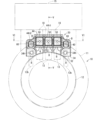
- FIG. 1 is a schematic front view showing an application example of the terminal block according to Embodiment 1.
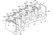
- FIG. 2 is a perspective view showing a terminal block.
- FIG. 3 is an exploded perspective view showing the terminal block.
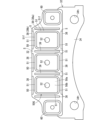
- FIG. 4 is a front view showing a heat sink.
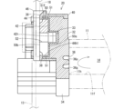
- FIG. 5 is a sectional view taken along line VV in FIG.
- FIG. 6 is a sectional view taken along line VI-VI in FIG.
- the terminal block of the present disclosure is as follows.
- a terminal block that is fixed to a case of a device and in which a conductive member is fastened with a bolt, the terminal block comprising a nut portion to which the bolt is screwed, and a heat sink that includes a heat radiating portion that comes into contact with a coolant that cools the device. and an insulating member that electrically insulates the nut portion and the heat sink, the heat sink including ribs positioned around the nut portion.
- the heat generated by the conductive member is easily transferred from the bolt to the heat sink via the rib. Thereby, the heat dissipation of the terminal block can be improved.
- the nut portion has a shape surrounded by a plurality of sides when viewed along the axial direction of the bolt, and the ribs correspond to all of the plurality of sides. It may be provided at a position where In this case, since the ribs are provided at positions corresponding to all of the plurality of sides, the heat of the nut portion is effectively transferred to the heat sink.
- the nut portion has a shape surrounded by a plurality of sides when viewed along the axial direction of the bolt, a plurality of the nut portions are provided, and the plurality of nut portions are spaced apart from each other to form a group of nuts, and the ribs are located at positions corresponding to all the sides located on the outer circumference of the group of nuts among the plurality of sides of each of the plurality of nut portions. may be provided. In this case, the ribs are provided at positions corresponding to all the sides located on the outer periphery of the nut group among the plurality of sides of each of the plurality of nut portions. transmitted to
- the rib may be provided at a position between the plurality of nut portions.
- the heat of the nut portions is effectively transmitted to the heat sink by the ribs positioned between the plurality of nut portions.
- the rib may be formed to extend along the side of the nut portion. In this case, for example, it can be located as close to the nut portion as possible while maintaining a preferable insulating distance to the nut portion. Thereby, the heat of the nut portion is effectively transmitted to the heat sink.
- the nut portion includes a plurality of outward side surfaces respectively corresponding to the plurality of sides, and the rib includes a plurality of It may be provided so as to face at least one of the outward side surfaces with a gap therebetween.
- the rib since the rib is provided so as to face at least one of the plurality of outward side surfaces with a gap, the heat of the nut portion is effectively transmitted to the heat sink.
- the rib is a first adjacent rib provided corresponding to adjacent sides forming an angle among the plurality of sides. and a second adjacent rib, wherein a gap is formed between the first adjacent rib and the second adjacent rib.
- first adjacent rib and a second adjacent rib are provided corresponding to sides adjacent to each other at an angle
- first adjacent rib and the second adjacent rib are continuous
- the first adjacent rib It may be difficult to precisely machine the corners at the boundary between the rib and the second adjacent rib.
- the protrusion height of the rib may be equal to or less than the surface height of the nut portion. This makes it difficult for the conductive member to interfere with the rib.
- the insulating member includes a first insulating portion interposed between the nut portion and the heat sink, and a periphery of the nut portion. and a surrounding second insulating portion, wherein the rib may be embedded in the second insulating portion.
- the nut portion and the heat sink can be insulated by the insulating member, and the nut portion can be held at a fixed position and a fixed posture. Since the ribs are buried in the second insulating portion, the heat of the nut portion is easily transferred to the heat sink via the ribs.
- FIG. 1 is a schematic front view showing an application example of the terminal block 20.
- the terminal block 20 is fixed to the case 11 of the first device 10 .
- the conductive members 13 and 18 are fastened and fixed to the terminal block 20 with bolts B. As shown in FIG. Thereby, the conductive member 13 and the conductive member 18 are electrically and mechanically connected.
- Conductive member 13 may be a member extending from first device 10 .
- Conductive member 18 may be a member extending from second device 15 . Therefore, the terminal block 20 can be used as a part for electrically connecting the first device 10 and the second device 15 .
- the first device 10 is, for example, a mechanical device having movable parts.
- the first device 10 is a rotating electrical machine that includes a case 11, an armature 12, and a magnetic field.
- FIG. 1 shows an example in which an armature 12 as a stator is fixed inside a tubular case 11 .
- the field is arranged in the armature 12 as a rotor.
- the magnetic field generated by the armature 12 rotates the magnetic field, or the rotation of the magnetic field causes the armature 12 to generate an electromotive force.
- the first device 10 includes coolant 14 for cooling the first device 10 .
- the coolant 14 is, for example, a liquid that flows through a coolant channel 11f (see FIG.
- the liquid flowing through the coolant channel 11f is, for example, water.
- a refrigerant may be enclosed in the case 11 .
- the liquid in this case may be, for example, lubricating oil.
- the second device 15 is an electrical device having a signal processing circuit.
- the second device 15 is an electrical device having control circuitry for controlling the first device 10 .
- the second device 15 is an inverter device that drives and controls the first device 10, which is a rotating electrical machine.
- the second device 15 may be integrated with the case 11 of the first device 10 by bolting or the like.
- a unit in which the first device 10, which is a mechanical device, and the second device having a control circuit for controlling the first device are thus integrated may be referred to as an electromechanical integrated unit.
- the conductive member 13 of the first device 10 is a busbar connected to the coil wire of the armature 12 .
- the conductive member 18 of the second device 15 is a busbar connected to the output terminal of the inverter circuit of the second device 15 .
- the bus bar is an elongated plate-shaped member made of a metal plate material such as copper or copper alloy, and has holes for fastening and fixing bolts B thereon.
- the first device 10 is a rotating electric machine that can be used as a three-phase AC motor. For this reason, three conductive members 13 extend from the armature 12 toward the case 11 in parallel with a space therebetween.
- three conductive members 18 extend from the second device 15 in parallel at the same intervals as the three conductive members 13 .
- a terminal block 20 is fixed to the end face of the case 11 on the opening side.
- the terminal block 20 is fixed to the case 11 by fastening bolts B, for example.
- the ends of the three conductive members 13 are overlapped with the ends of the corresponding three conductive members 18 .
- the bolt B passes through the conductive members 13 and 18 and is screwed into the nut portion 50 of the terminal block 20 .
- the conductive members 13 and 18 are fixed at a fixed position on the terminal block 20 while being in contact with each other, and the conductive members 13 and 18 are electrically connected.
- the opening of the case 11 is closed by a lid.
- the number of conductive members 13 and 18 connected by the terminal block 20 is arbitrary. Also, one of the conductive members to be connected may be integrally supported by the terminal block 20 before being fastened and fixed by the bolts B. As shown in FIG.
- FIG. 2 is a perspective view showing the terminal block 20.
- FIG. FIG. 3 is an exploded perspective view showing the terminal block 20.
- FIG. FIG. 3 shows a state in which the heat sink 30 is separated from the insulating member 40 and one of the plurality of nut portions 50 is separated from the insulating member 40 .
- FIG. 4 is a front view showing the heat sink 30.
- FIG. 5 is a sectional view taken along line VV in FIG. 1
- FIG. 6 is a sectional view taken along line VI-VI in FIG.
- the terminal block 20 includes a nut portion 50, a heat sink 30, and an insulating member 40.
- the nut portion 50 is a nut to which the bolt B is screwed.
- the nut portion 50 is, for example, a member in which a screw hole 52 is formed.
- the nut portion 50 preferably has a non-circular outer peripheral shape so that it can be held in a non-rotating state by the insulating member 40 .
- the nut portion 50 has a shape surrounded by a plurality of sides 51 when viewed along the axial direction of the bolt B (that is, the axial direction of the screw hole 52).
- the multiple sides 51 are, for example, straight lines. Sides 51 that are adjacent in the circumferential direction of the nut portion 50 may form a curved line.
- the nut portion 50 is formed in a square shape when viewed along the axial direction of the bolt B, more specifically, in a rectangular shape with a pair of opposite sides longer than the other pair of opposite sides. It is also conceivable that the nut portion 50 is formed in other polygonal shapes, such as hexagonal shapes.
- a pair of main surfaces 50a and 50b on both sides in the thickness direction of the nut portion 50 are surfaces facing opposite sides and parallel to each other.
- One main surface 50a can come into surface contact with the bottom surface of the nut accommodating recess 44h1 of the insulating member 40.
- the other main surface 50b can be in surface contact with the conductive member 13 or the conductive member 18 .
- the terminal block 20 has three nut portions 50 corresponding to the number of connections of the conductive members 13 and 18 .
- An arbitrary number of nut portions 50 is provided according to the number of connections of the conductive members 13 and 18 to be fastened.
- the terminal block 20 may have another nut portion 60 .
- the heat sink 30 is made of a thermally conductive material.
- the thermally conductive material is a material having better thermal conductivity than the insulating member 40, and is, for example, a metal such as aluminum or an aluminum alloy.
- the heat sink 30 is, for example, a component integrally formed by cutting metal.
- the heat sink 30 may be formed by die processing, press processing, or the like.
- Heat sink 30 includes a nut support base portion 32 and a fixed base portion 34 .
- the nut support base portion 32 is formed in an elongated plate-like portion.
- a nut portion 50 and a nut portion 60 are supported on one main surface of the nut support base portion 32 via an insulating member 40 .
- three nut portions 50 are positioned in the middle portion of the nut support base portion 32 in the longitudinal direction, and two nut portions 50 are positioned at both longitudinal end portions of the nut support base portion 32 .
- a bolt relief hole 33 is formed on one main surface of the nut support base portion 32 .
- the bolt escape hole 33 is a hole with a bottom, and is located on the extension of the screw holes of each nut portion 50 and each nut portion 60 .
- the fixed base portion 34 is an elongated plate-like portion extending from one side of the nut support base portion 32 in the short direction toward the outside of the nut support base portion 32 .
- the fixed base portion 34 is thinner than the nut support base portion 32 and a step is formed between the fixed base portion 34 and the nut support base portion 32 .
- a fixing hole 34 h is formed in the fixing base portion 34 .
- fixing holes 34h are formed at both longitudinal ends of the fixing base portion 34.
- the terminal block 20 is fixed to the case 11 by screwing the bolt B into a screw hole formed in the case 11 while the bolt B is inserted through the main fixing hole 34h.
- the extension position of the fixed base portion 34 with respect to the nut support base portion 32 is arbitrary. For example, on the outer extension of both longitudinal ends of the nut support base portion 32, a fixing base portion having a fixing hole may extend.
- the heat sink 30 has a heat radiation portion 36 with which the coolant 14 that cools the first device 10 contacts.
- the heat radiation portion 36 is formed in a portion facing the case 11 side when the terminal block 20 is fixed to the case 11 .
- the coolant channel 11f formed in the case 11 opens at a portion of the open end surface of the case 11 where the terminal block 20 is attached.
- the heat sink 30 is fixed to the case 11 so as to close the opening 11h.
- a heat radiating portion 36 is formed in a portion of the case 11 that closes the opening 11h.
- the heat radiating portion 36 is formed on the other main surface of the heat sink 30 facing away from the nut portion 50 .
- the other main surface of the heat sink 30 is formed with an arc-shaped groove 36g along the open end surface of the case 11.
- the heat radiation portion 36 is configured to include the surface of the groove 36g.
- the coolant 14 can flow closer to the nut portion 50 and the contact area between the coolant 14 and the heat sink 30 increases. Thereby, the heat of the heat sink 30 can be effectively transferred to the coolant 14 .
- an arcuate protrusion 36p is formed at the bottom of the groove 36g.
- the heat radiating portion 36 includes the surface of the arc-shaped convex portion 36p. The arc-shaped projections 36 p further increase the contact area between the coolant 14 and the heat sink 30 , and the heat of the heat sink 30 can be transmitted to the coolant 14 more effectively.
- the heat radiating portion may be a through hole that passes through the heat sink 30 and through which a coolant flows. If the heat sink 30 has a portion with which the coolant 14 contacts, the portion can be used as a heat radiation portion.
- the heat radiating portion 36 may be a portion cooled by oil enclosed in the case 11 .
- the heat sink 30 includes ribs 38 , 39 positioned around the nut portion 50 .
- Ribs 38 and 39 are formed to protrude from one main surface of nut support base portion 32 so as to be positioned around nut portion 50 .
- a specific configuration example of the ribs 38 and 39 will be described in more detail later.
- the insulating member 40 is a member that electrically insulates the nut portion 50 and the heat sink 30 from each other.
- the insulating member 40 is, for example, a member integrally molded with a resin.
- the insulating member 40 is, for example, a member that is molded using the heat sink 30 as an insert.
- the insulating member 40 includes a first insulating portion 42 , a second insulating portion 44 , and partitions 46 and 47 .
- the first insulating portion 42 is a portion interposed between the nut portion 50 and the heat sink 30 .
- the second insulating portion 44 is a portion surrounding the nut portion 50 .
- the second insulating portion 44 also includes a portion surrounding the nut portion 60 .
- the partition portion 46 is a portion that partitions the nut portion 50 or the conductive members 13 and 18 connected to the nut portion 50 from other portions
- the partition portion 47 is a portion that separates the nut portion 60 and the conductive member connected to the nut portion. 13b from other parts.
- the first insulating portion 42 is formed in an elongated plate shape that extends entirely on one main surface of the nut support base portion 32 . Since the nut portions 50 and 60 are arranged on the first insulating portion 42 , the nut portions 50 and 60 are kept electrically insulated from the heat sink 30 by the first insulating portion 42 .
- the first insulating portion 42 may cover part or all of the outer periphery of the nut support base portion 32 . It should be noted that most of the fixed base portion 34 is exposed from the insulating member 40 in this embodiment.
- a bolt relief hole 42h is formed in the surface of the first insulating portion 42 on which the nut portions 50 and 60 are arranged.
- the bolt relief hole 42h is a bottomed hole formed at a position corresponding to the bolt relief hole 33, and is located on the extension of the screw holes of the nut portions 50 and 60. As shown in FIG.
- the second insulating portion 44 protrudes from the surface of the first insulating portion 42 on which the nut portions 50 and 60 are arranged so as to surround the nut portions 50 and 60 . That is, the insulating member 40 is formed with a nut accommodating recess 44h1 that can accommodate the nut portion 50 at a fixed position while the nut portion 50 is restricted from rotating. A portion forming the bottom of the nut accommodating recess 44h1 is the first insulating portion 42, and a portion forming the peripheral wall of the nut accommodating recess 44h1 is the second insulating portion 44. As shown in FIG.
- the insulating member 40 is formed with a nut accommodating recess 44h2 that can accommodate the nut portion 60 at a fixed position while the nut portion 60 is restricted from rotating.
- the portion forming the bottom of the nut accommodating recess 44h2 is the first insulating portion 42, and the portion forming the peripheral wall of the nut accommodating recess 44h2 is the second insulating portion 44. As shown in FIG.
- three nut accommodating recesses 44h1 corresponding to the three nut portions 50 are formed in the insulating member 40 so as to be linearly spaced apart.
- Two nut housing recesses 44h2 are formed outside the three nut housing recesses 44h1 in the direction in which the three nut housing recesses 44h1 are arranged.
- each of the three nut portions 50 is accommodated in the three nut portions 50, so that the nut portions 50 are held in a state in which rotation is restricted so as to be arranged in a straight line with an interval therebetween.
- the two nut portions 60 are held in a state in which rotation is restricted outside the three nut portions 50 in the direction in which the three nut portions 50 are arranged. Since the nut portions 50 and 60 are individually housed in the nut housing recesses 44h1 and 44h2, the nut portions 50 and 60 are kept electrically insulated from each other by the insulating member 40.
- the nut accommodating recesses 44h1 and 44h2 may be formed by molding the insulating member 40 using the nut portions 50 and 60 as insert portions.
- the insulating member 40 including the shapes of the nut accommodating recesses 44h1 and 44h2 may be molded separately from the nut parts 50 and 60, and the nut parts 50 and 60 may be fitted into the nut accommodating recesses 44h1 and 44h2.
- the number and positions of the nut portions 50 and 60 and the nut housing recesses 44h1 and 44h2 can be appropriately changed according to the number and arrangement of the conductive members 13, 13b and 18 to be connected.
- the partition portion 46 is a portion extending from the first insulating portion 42 and the second insulating portion 44 in a direction intersecting the direction in which the plurality of nut portions 50 are arranged. More specifically, the partitions 46 are positioned between the plurality of nut-accommodating recesses 44h1 and between the nut-accommodating recesses 44h1 and 44h2.
- the partition part 46 has an elongated plate-like part extending from the second insulating part 44 to the side opposite to the first insulating part 42 , and an elongated plate-like part extending from the first insulating part 42 and the second insulating part 44 to the fixed base part 34 side. It includes a plate-shaped portion that comes out. Due to the relationship between the adjacent nut portions 50 and 60, the partition portion 46 prevents the conductive members 13, 13b, and 18 from coming into contact with each other.
- the partition part 47 is a part extending from the first insulating part 42 and the second insulating part 44 in a direction crossing the direction in which the plurality of nut parts 50 and 60 are arranged. More specifically, the partitions 47 are positioned outside the partitions 46 at both ends in the direction in which the plurality of nut housing recesses 44h1 and 44h2 are arranged.
- the partition part 47 includes a curved plate-like part extending from the second insulating part 44 to the side opposite to the first insulating part 42 and partially surrounding the nut accommodating recess 44h2, the first insulating part 42 and the first insulating part 42 2 and a plate-like portion extending from the insulating portion 44 toward the fixed base portion 34 side.
- the partition portion 47 prevents the conductive member 13b connected to the nut portion 60 from coming into contact with the surrounding portion.
- the shape of the partitions 46 and 47 is not limited to the shape described above and is arbitrary.
- the partitions 46 and 47 are not essential and may be omitted.
- the insulating member 40 is a member that is molded using the heat sink 30 as an insert.
- the insulating member 40 may be a member that is molded separately from the heat sink 30 and then combined with the heat sink 30 .
- the insulating member 40 may be configured by combining a plurality of resin parts.
- the plurality of resin parts may be configured by a combination of a primary molded portion and a secondary molded portion molded by using the primary molded portion as an insert portion.
- the primary molded portion may be a portion that is molded using the heat sink 30 as an insert portion, or may be molded separately from the heat sink 30 and combined with the heat sink 30 .
- the ribs 38 , 39 are positioned around the nut portion 50 . If the ribs 38 and 39 are formed at such a position that the heat of the nut portion 50 is transferred to the ribs 38 and 39 through the portion of the insulating member 40 between the nut portion 50 and the ribs 38 and 39. Well, the position around the nut portion 50 is not particularly limited.
- the ribs 38 and 39 may be provided at positions corresponding to all of the multiple (four in this embodiment) sides 51 surrounding the nut portion 50 .
- the ribs 38 and 39 are provided at positions corresponding to all of the sides 51 surrounding the nut portion 50 on all of the plurality of nut portions 50 .
- the positions of the ribs 38 and 39 will be described in relation to the plurality (three in this embodiment) of the nut portions 50 .
- Ribs 38 are provided at positions corresponding to all sides 51 positioned on the outer circumference of the nut group 50G among the plurality of sides 51 of each of the plurality of nut portions 50 . Therefore, the ribs 38 can be arranged as long as possible on the outer periphery of the nut group 50G. Thereby, the heat of the nut group 50G can be effectively conducted to the rib 38. As shown in FIG.
- ribs 39 are provided at positions between adjacent nut portions 50 in the nut group 50G. Only one rib 39 is provided between adjacent nut portions 50 . Therefore, the heat from adjacent nut portions 50 is transferred to one rib 39 between the adjacent nut portions 50 . In addition, between the adjacent nut portions 50 , two ribs may be provided near one side and the other side of the adjacent nut portions 50 .
- the ribs 38 and 39 are formed in elongated plate shapes protruding from one main surface of the first insulating portion 42 .
- the ribs 38 and 39 are formed to extend along the side 51 of the nut portion 50 when viewed along the axial direction of the bolt B. As shown in FIG. In other words, when viewed along the axial direction of the bolt B, the ribs 38 and 39 extend linearly while keeping an equal distance from the side 51 of the nut portion 50 .
- An outward side surface 51f corresponding to each side 51 of the nut portion 50 is an outward surface orthogonal to the axial direction of the bolt B.
- the ribs 38, 39 face the outward side surface 51f with a gap therebetween.
- a gap of equal width is formed between the outward side surface 51f of the nut portion 50 and the side surface of the ribs 38 and 39 on the nut portion 50 side.
- the ribs 38, 39 corresponding to each side 51 are separated from each other.
- the rib 38 includes a first adjacent rib 38a and a second adjacent rib 38b provided corresponding to adjacent sides 51 forming an angle (90° in this embodiment) with each other among the plurality of sides.
- FIG. 4 shows an example of such a first adjacent rib 38a and a second adjacent rib 38b.
- a gap S is formed between the first adjacent rib 38a and the second adjacent rib 38b. For example, when the extension line of the first adjacent rib 38a and the extension line of the second adjacent rib 38b intersect at an angle, the gap S is formed at the position corresponding to the intersection.
- the first adjacent rib 38a and the second adjacent rib 38b are formed continuously. 38a and the second adjacent rib 38b can be easily formed. For example, if the first adjacent rib 38a and the second adjacent rib 38b are connected at an angle, the inward surface of the first adjacent rib 38a and the inward surface of the second adjacent rib 38b are processed to form a continuous shape. It will be done. Since it is difficult to process an internal corner shape in which surfaces form an angle and continue to form an angle by cutting or the like, processing into a shape in which surfaces are connected via a curved surface is assumed. In that case, the rib approaches the nut portion 50 by the curved surface.
- the rib is set at a position farther from the side 51 than the rib approaches the nut portion 50 on the curved surface. Then, the heat of the nut part 50 becomes difficult to be transmitted to the rib.
- the first adjacent rib 38a and the second adjacent rib 38b By providing the gap S between the first adjacent rib 38a and the second adjacent rib 38b, there is no restriction on processing of the portion connecting the first adjacent rib 38a and the second adjacent rib 38b, and the first adjacent rib
- the first adjacent rib 38a and the second adjacent rib 38b can be arranged closer to the side 51 as long as a desired insulating distance can be secured between the rib 38a and the second adjacent rib 38b. Thereby, heat is effectively transferred from the nut portion 50 to the first adjacent rib 38a and the second adjacent rib 38b.
- the ribs 38 and 39 are provided corresponding to each side 51, and the gap S is provided between all adjacent ribs 38 and 39. As shown in FIG.
- adjacent ribs may be connected via an angular or curved portion.
- the ribs 38 and 39 pass through the first insulating portion 42 covering one main surface of the nut support base portion 32 and are buried in the second insulating portion 44 .
- the ribs 38 and 39 are not exposed in the nut housing recesses 44h1 and 44h2, nor are they exposed on the side of the second insulating portion 44 opposite to the first insulating portion 42.
- the insulating member 40 is interposed between the ribs 38 , 39 and the nut portion 50 , and electrically insulates the ribs 38 , 39 from the nut portion 50 by the insulating member 40 .
- the protrusion height of the ribs 38, 39 is, for example, equal to or less than the surface height of the nut portion 50. More specifically, the protrusion height of the ribs 38 and 39 with respect to the one main surface of the nut support base portion 32 is the height position of the outer main surface of the nut portion 50 with the one main surface of the nut support base portion 32 as a reference. is equal to or less than As a result, the ribs 38 and 39 are less likely to protrude from the nut portion 50 around the nut portion 50 , and are less likely to hinder fastening and fixing of the conductive members 13 and 18 to the nut portion 50 .
- the height of the rib 38 may exceed the nut portion 50 between the nut portions 50 or on the outer side of the nut group 50G in the parallel direction.
- the protrusion height of the ribs 38 and 39 exceeds, for example, the position of the inner main surface of the nut portion 50 with one main surface of the nut support base portion 32 as a reference. In other words, in the axial direction of the bolt B, the ribs 38 and 39 and the nut portion 50 overlap each other. As a result, the heat of the nut portion 50 is easily transferred to the ribs 38 and 39 .
- the first device 10 which is a mechanical device
- the second device 15 which is an electrical device having a signal processing circuit
- the first device 10 and the second device 15 are connected via the conductive members 13, 18, which are short and hardly exposed to the outside. Therefore, there is a possibility that the heat generated in the first device 10 and the heat generated by the electricity flowing through the conductive members 13 and 18 are easily transferred to the second device 15 .
- the heat of the conductive members 13 and 18, which can be heat transfer paths or heat sources can be efficiently transferred to the heat sink 30 at the terminal block 20. FIG. This makes it difficult for heat to be conducted to the second device 15 .
- the heat of the conductive members 13 and 18 can be transferred to the heat sink 30 for cooling.
- the ribs 38 and 39 are provided at positions corresponding to all of the multiple sides 51 surrounding the nut portion 50 , the heat of the nut portion 50 is effectively transmitted to the heat sink 30 .
- the ribs 38 are provided at positions corresponding to all the sides 51 located on the outer periphery of the nut group 50G. It is effectively transmitted to the heat sink 30.
- the heat of the nut portions 50 is effectively transmitted to the heat sink 30 also by the ribs 39 positioned between the plurality of nut portions 50 .
- the ribs 38 and 39 are formed to extend along the side 51 of the nut portion 50 . Therefore, for example, the ribs 38 and 39 can be positioned as close to the nut portion 50 as possible while maintaining a preferable insulating distance from the nut portion 50 . As a result, the heat of the nut portion 50 can be effectively transmitted to the heat sink 30 while maintaining insulation performance.
- the gap S is provided between the adjacent ribs 38 and 39, it is possible to eliminate restrictions on processing when forming adjacent ribs continuously, for example. Thereby, it is easy to process a shape in which the ribs 38 and 39 are arranged as close to the nut portion 50 as possible while maintaining an insulation distance between the ribs 38 and 39 and the nut portion 50 .
- the protrusion height of the ribs 38 and 39 is equal to or less than the surface height of the nut portion 50 , the conductive members 13 and 18 fastened and fixed to the nut portion 50 are less likely to interfere with the ribs 38 and 39 .
- the ribs 38 and 39 are the second insulating portion. It is buried in 44. Therefore, the ribs 38 and 39 are arranged on the outer peripheral side of the nut portion 50 , and the heat of the nut portion 50 is easily transferred to the heat sink 30 via the ribs 38 and 39 .
- the terminal block 20 does not need to connect the conductive member 13 of the first device 10 and the conductive member 18 of the second device 15 integrated with the first device 10 .
- a conductive member extending from a device remote from the first device 10 may be connected to the conductive member 13 of the first device 10 .
- Second device 20
- Terminal block 30
- Heat sink 32
- Bolt relief hole 34
- Fixed base 34h
- Fixing hole 36
- Heat dissipation part 36g groove
- 36p arc-shaped protrusions 38, 39
- rib 38a first adjacent rib 38b second adjacent rib
- insulating member 42
- first insulating portion 44
- second insulating portion 44h1, 44h2 nut accommodating recessed portion 46, 47 partitioning portions 50, 60 nut portion 50G Nut group 50a, 50b
- Main surface 51 of nut portion Side 51f of nut portion Outward side surface 52
- Screw hole B B
Landscapes
- Physics & Mathematics (AREA)
- Thermal Sciences (AREA)
- Engineering & Computer Science (AREA)
- Microelectronics & Electronic Packaging (AREA)
- Connections Arranged To Contact A Plurality Of Conductors (AREA)
- Cooling Or The Like Of Electrical Apparatus (AREA)
Priority Applications (2)
| Application Number | Priority Date | Filing Date | Title |
|---|---|---|---|
| US18/700,043 US20250246825A1 (en) | 2021-10-20 | 2022-09-29 | Terminal block |
| CN202280067842.1A CN118160163A (zh) | 2021-10-20 | 2022-09-29 | 端子台 |
Applications Claiming Priority (2)
| Application Number | Priority Date | Filing Date | Title |
|---|---|---|---|
| JP2021171746A JP7600952B2 (ja) | 2021-10-20 | 2021-10-20 | 端子台 |
| JP2021-171746 | 2021-10-20 |
Publications (1)
| Publication Number | Publication Date |
|---|---|
| WO2023068006A1 true WO2023068006A1 (ja) | 2023-04-27 |
Family
ID=86059157
Family Applications (1)
| Application Number | Title | Priority Date | Filing Date |
|---|---|---|---|
| PCT/JP2022/036389 Ceased WO2023068006A1 (ja) | 2021-10-20 | 2022-09-29 | 端子台 |
Country Status (4)
| Country | Link |
|---|---|
| US (1) | US20250246825A1 (https=) |
| JP (1) | JP7600952B2 (https=) |
| CN (1) | CN118160163A (https=) |
| WO (1) | WO2023068006A1 (https=) |
Families Citing this family (1)
| Publication number | Priority date | Publication date | Assignee | Title |
|---|---|---|---|---|
| CN115884563B (zh) * | 2021-09-27 | 2025-04-01 | 中兴智能科技南京有限公司 | 散热组件及散热器 |
Citations (3)
| Publication number | Priority date | Publication date | Assignee | Title |
|---|---|---|---|---|
| JP2011187838A (ja) * | 2010-03-10 | 2011-09-22 | Shindengen Electric Mfg Co Ltd | トランスの取付構造 |
| JP2012151038A (ja) * | 2011-01-20 | 2012-08-09 | Sumitomo Wiring Syst Ltd | 端子台及び端子台の製造方法 |
| JP2017118672A (ja) * | 2015-12-24 | 2017-06-29 | 矢崎総業株式会社 | 電気接続箱 |
-
2021
- 2021-10-20 JP JP2021171746A patent/JP7600952B2/ja active Active
-
2022
- 2022-09-29 CN CN202280067842.1A patent/CN118160163A/zh active Pending
- 2022-09-29 WO PCT/JP2022/036389 patent/WO2023068006A1/ja not_active Ceased
- 2022-09-29 US US18/700,043 patent/US20250246825A1/en active Pending
Patent Citations (3)
| Publication number | Priority date | Publication date | Assignee | Title |
|---|---|---|---|---|
| JP2011187838A (ja) * | 2010-03-10 | 2011-09-22 | Shindengen Electric Mfg Co Ltd | トランスの取付構造 |
| JP2012151038A (ja) * | 2011-01-20 | 2012-08-09 | Sumitomo Wiring Syst Ltd | 端子台及び端子台の製造方法 |
| JP2017118672A (ja) * | 2015-12-24 | 2017-06-29 | 矢崎総業株式会社 | 電気接続箱 |
Also Published As
| Publication number | Publication date |
|---|---|
| JP2023061671A (ja) | 2023-05-02 |
| CN118160163A (zh) | 2024-06-07 |
| US20250246825A1 (en) | 2025-07-31 |
| JP7600952B2 (ja) | 2024-12-17 |
Similar Documents
| Publication | Publication Date | Title |
|---|---|---|
| CN106796933B (zh) | 电源组件和电力转换装置 | |
| EP2495817B1 (en) | Terminal block, motor provided therewith and method of mounting a terminal block | |
| JP6409968B2 (ja) | 機電一体型の回転電機装置 | |
| JP4054137B2 (ja) | パワー半導体素子の給電及び放熱装置 | |
| US10332822B2 (en) | Pedestal surface for MOSFET module | |
| US10727655B2 (en) | Conduction path | |
| US20140239755A1 (en) | Rotating electrical machine | |
| US20140239750A1 (en) | Rotating electrical machine | |
| JP7483963B2 (ja) | 電源装置 | |
| JP6129286B1 (ja) | 電力供給ユニット一体型回転電機 | |
| JP7366082B2 (ja) | 電力変換装置 | |
| JP7282265B2 (ja) | 電力変換装置 | |
| JP2019003893A (ja) | 端子台、及び電動機 | |
| US20240195316A1 (en) | Cooled High-Current System | |
| WO2023068006A1 (ja) | 端子台 | |
| US11632013B2 (en) | Control device and motor device that ensure heat dissipation while reducing the size of the motor device | |
| JP6068933B2 (ja) | 車両用モータユニット | |
| JP2006271063A (ja) | バスバーの冷却構造 | |
| JP7069733B2 (ja) | 放熱用ブロックおよび電力変換装置 | |
| WO2022215356A1 (ja) | 電気導体の冷却装置、電力変換装置及び回転電気機械 | |
| US20240373603A1 (en) | Power conversion device and drive device | |
| JP2019187202A (ja) | モータ装置 | |
| JP2024063776A (ja) | 電力変換器 | |
| JP2025123596A (ja) | 電気接続箱 | |
| CN115118065A (zh) | 铜排接线座及电驱动总成 |
Legal Events
| Date | Code | Title | Description |
|---|---|---|---|
| 121 | Ep: the epo has been informed by wipo that ep was designated in this application |
Ref document number: 22883314 Country of ref document: EP Kind code of ref document: A1 |
|
| WWE | Wipo information: entry into national phase |
Ref document number: 202280067842.1 Country of ref document: CN |
|
| WWE | Wipo information: entry into national phase |
Ref document number: 18700043 Country of ref document: US |
|
| NENP | Non-entry into the national phase |
Ref country code: DE |
|
| 122 | Ep: pct application non-entry in european phase |
Ref document number: 22883314 Country of ref document: EP Kind code of ref document: A1 |
|
| WWP | Wipo information: published in national office |
Ref document number: 18700043 Country of ref document: US |