WO2023068006A1 - Terminal block - Google Patents
Terminal block Download PDFInfo
- Publication number
- WO2023068006A1 WO2023068006A1 PCT/JP2022/036389 JP2022036389W WO2023068006A1 WO 2023068006 A1 WO2023068006 A1 WO 2023068006A1 JP 2022036389 W JP2022036389 W JP 2022036389W WO 2023068006 A1 WO2023068006 A1 WO 2023068006A1
- Authority
- WO
- WIPO (PCT)
- Prior art keywords
- nut
- terminal block
- rib
- sides
- ribs
- Prior art date
Links
Images


Classifications
-
- H—ELECTRICITY
- H01—ELECTRIC ELEMENTS
- H01R—ELECTRICALLY-CONDUCTIVE CONNECTIONS; STRUCTURAL ASSOCIATIONS OF A PLURALITY OF MUTUALLY-INSULATED ELECTRICAL CONNECTING ELEMENTS; COUPLING DEVICES; CURRENT COLLECTORS
- H01R9/00—Structural associations of a plurality of mutually-insulated electrical connecting elements, e.g. terminal strips or terminal blocks; Terminals or binding posts mounted upon a base or in a case; Bases therefor
- H01R9/22—Bases, e.g. strip, block, panel
-
- H—ELECTRICITY
- H05—ELECTRIC TECHNIQUES NOT OTHERWISE PROVIDED FOR
- H05K—PRINTED CIRCUITS; CASINGS OR CONSTRUCTIONAL DETAILS OF ELECTRIC APPARATUS; MANUFACTURE OF ASSEMBLAGES OF ELECTRICAL COMPONENTS
- H05K7/00—Constructional details common to different types of electric apparatus
- H05K7/20—Modifications to facilitate cooling, ventilating, or heating
Abstract
The purpose of the present disclosure is to improve the heat dissipating properties of a terminal block. Provided is a terminal block which is secured to the case of an apparatus and to which a conductive member is fastened using a bolt. The terminal block comprises: a nut with which a bolt threadedly engages; a heat sink that includes a heat dissipating part with which a refrigerant for cooling the apparatus contacts; and an insulative member that electrically insulates the nut and the heat sink. The heat sink includes a rib which is located in the periphery of the nut.
Description
本開示は、端子台に関する。
The present disclosure relates to terminal blocks.
特許文献1-3は、端子台に関する技術を開示している。例えば、特許文献3には、モータケースに固定され、ボルトを締め込むことによってバスバを締結する端子台であって、ボルトを締め込むためのナットと、ナットの後方に絶縁プレートを介して密着するアルミダイキャスト製のヒートシンクとを備え、ヒートシンクには、モータケースの冷媒流路を通る冷却水と接触する放熱部が設けられることが開示されている。
Patent Documents 1 to 3 disclose technologies related to terminal blocks. For example, Patent Document 3 discloses a terminal block that is fixed to a motor case and fastens a busbar by tightening a bolt. A heat sink made of die-cast aluminum is provided, and the heat sink is provided with a heat radiating portion that contacts cooling water flowing through a coolant flow path of the motor case.
端子台の適用対象となるユニットの小型化及び高出力化に伴い、エネルギー密度が上昇することが考えられる。このため、端子台においても、放熱性をさらに向上させることが望まれている。
It is conceivable that the energy density will increase as the unit to which the terminal block is applied becomes smaller and more powerful. For this reason, it is desired to further improve the heat dissipation property of the terminal block as well.
そこで、本開示は、端子台の放熱性を向上させることを目的とする。
Therefore, an object of the present disclosure is to improve the heat dissipation of the terminal block.
本開示の端子台は、機器のケースに固定され、導電部材がボルトによって締結される端子台であって、前記ボルトが螺合されるナット部と、前記機器を冷却する冷媒が接触する放熱部を含むヒートシンクと、前記ナット部と前記ヒートシンクとを電気的に絶縁する絶縁部材と、を備え、前記ヒートシンクは、前記ナット部の周囲に位置するリブを含む、端子台である。
The terminal block of the present disclosure is a terminal block that is fixed to a case of a device and in which a conductive member is fastened with a bolt, a nut portion to which the bolt is screwed, and a heat radiating portion in contact with a coolant that cools the device. and an insulating member that electrically insulates the nut portion and the heat sink, wherein the heat sink includes ribs positioned around the nut portion.
本開示によれば、端子台の放熱性を向上させることができる。
According to the present disclosure, it is possible to improve the heat dissipation of the terminal block.
[本開示の実施形態の説明]
最初に本開示の実施態様を列記して説明する。 [Description of Embodiments of the Present Disclosure]
First, the embodiments of the present disclosure are listed and described.
最初に本開示の実施態様を列記して説明する。 [Description of Embodiments of the Present Disclosure]
First, the embodiments of the present disclosure are listed and described.
本開示の端子台は、次の通りである。
The terminal block of the present disclosure is as follows.
(1)機器のケースに固定され、導電部材がボルトによって締結される端子台であって、前記ボルトが螺合されるナット部と、前記機器を冷却する冷媒が接触する放熱部を含むヒートシンクと、前記ナット部と前記ヒートシンクとを電気的に絶縁する絶縁部材と、を備え、前記ヒートシンクは、前記ナット部の周囲に位置するリブを含む、端子台である。
(1) A terminal block that is fixed to a case of a device and in which a conductive member is fastened with a bolt, the terminal block comprising a nut portion to which the bolt is screwed, and a heat sink that includes a heat radiating portion that comes into contact with a coolant that cools the device. and an insulating member that electrically insulates the nut portion and the heat sink, the heat sink including ribs positioned around the nut portion.
本端子台によると、導電部材で生じた熱がボルトからリブを経由してヒートシンクに伝わり易い。これにより、端子台の放熱性を向上させることができる。
According to this terminal block, the heat generated by the conductive member is easily transferred from the bolt to the heat sink via the rib. Thereby, the heat dissipation of the terminal block can be improved.
(2)(1)の端子台であって、前記ナット部は、前記ボルトの軸方向に沿って見て複数の辺で囲まれる形状であり、前記リブは、前記複数の辺の全てに対応する位置に設けられてもよい。この場合、リブが、複数の辺の全てに対応する位置に設けられるため、ナット部の熱が効果的にヒートシンクに伝わる。
(2) In the terminal block of (1), the nut portion has a shape surrounded by a plurality of sides when viewed along the axial direction of the bolt, and the ribs correspond to all of the plurality of sides. It may be provided at a position where In this case, since the ribs are provided at positions corresponding to all of the plurality of sides, the heat of the nut portion is effectively transferred to the heat sink.
(3)(1)の端子台であって、前記ナット部は、前記ボルトの軸方向に沿って見て複数の辺で囲まれる形状であり、前記ナット部を複数備え、前記複数のナット部が互いに離間しつつ並設されてナット群が構成され、前記リブは、前記複数のナット部のそれぞれの前記複数の辺のうち、前記ナット群の外周に位置する全ての辺に対応する位置に設けられてもよい。この場合、リブが、前記複数のナット部のそれぞれの前記複数の辺のうち、前記ナット群の外周に位置する全ての辺に対応する位置に設けられるため、ナット部の熱が効果的にヒートシンクに伝わる。
(3) In the terminal block of (1), the nut portion has a shape surrounded by a plurality of sides when viewed along the axial direction of the bolt, a plurality of the nut portions are provided, and the plurality of nut portions are spaced apart from each other to form a group of nuts, and the ribs are located at positions corresponding to all the sides located on the outer circumference of the group of nuts among the plurality of sides of each of the plurality of nut portions. may be provided. In this case, the ribs are provided at positions corresponding to all the sides located on the outer periphery of the nut group among the plurality of sides of each of the plurality of nut portions. transmitted to
(4)(3)の端子台であって、前記リブは、前記複数のナット部の間の位置に設けられてもよい。この場合、複数のナット部の間に位置するリブによって、ナット部の熱が効果的にヒートシンクに伝わる。
(4) In the terminal block of (3), the rib may be provided at a position between the plurality of nut portions. In this case, the heat of the nut portions is effectively transmitted to the heat sink by the ribs positioned between the plurality of nut portions.
(5)(2)から(4)のいずれか1つの記載の端子台であって、前記リブは、前記ナット部の前記辺に沿って延びるように形成されていてもよい。この場合、例えば、ナット部に対して好ましい絶縁距離を保ちつつ、当該ナット部に対してなるべく近くに位置することができる。これにより、ナット部の熱が効果的にヒートシンクに伝わる。
(5) In the terminal block described in any one of (2) to (4), the rib may be formed to extend along the side of the nut portion. In this case, for example, it can be located as close to the nut portion as possible while maintaining a preferable insulating distance to the nut portion. Thereby, the heat of the nut portion is effectively transmitted to the heat sink.
(6)(2)から(5)のいずれか1つの端子台であって、前記ナット部は、前記複数の辺のそれぞれに対応する複数の外向き側面を含み、前記リブは、前記複数の外向き側面の少なくとも1つに間隔をあけて対向するように設けられていてもよい。この場合、リブは、前記複数の外向き側面の少なくとも1つに間隔をあけて対向するように設けられているため、ナット部の熱が効果的にヒートシンクに伝わる。
(6) In the terminal block according to any one of (2) to (5), the nut portion includes a plurality of outward side surfaces respectively corresponding to the plurality of sides, and the rib includes a plurality of It may be provided so as to face at least one of the outward side surfaces with a gap therebetween. In this case, since the rib is provided so as to face at least one of the plurality of outward side surfaces with a gap, the heat of the nut portion is effectively transmitted to the heat sink.
(7)(2)から(6)のいずれか1つの端子台であって、前記リブは、前記複数の辺のうち互いに角度をなして隣合う辺に対応して設けられた第1隣接リブと第2隣接リブとを含み、前記第1隣接リブと前記第2隣接リブとの間に隙間が形成されていてもよい。
(7) In the terminal block according to any one of (2) to (6), the rib is a first adjacent rib provided corresponding to adjacent sides forming an angle among the plurality of sides. and a second adjacent rib, wherein a gap is formed between the first adjacent rib and the second adjacent rib.
例えば、互いに角度をなして隣合う辺に対応して第1隣接リブと第2隣接リブとを設ける場合、仮に第1隣接リブと第2隣接リブとが連続していると、第1隣接リブと第2隣接リブとの境界で角の精密な加工が難しくなる可能性がある。この場合、角の加工の制約に起因して、絶縁性を確保するために、ナット部に対して第1隣接リブと第2隣接リブとを離れた位置に設けることが考えられる。第1隣接リブと第2隣接リブとの間に隙間が形成されていると、角の加工による制約が無くなり、ナット部に対して第1隣接リブと第2隣接リブとを近づけた位置に配置し易い。これにより、第1隣接リブと第2隣接リブとを連続的に形成する場合と比較して、端子台を小型化できる。
For example, when a first adjacent rib and a second adjacent rib are provided corresponding to sides adjacent to each other at an angle, if the first adjacent rib and the second adjacent rib are continuous, the first adjacent rib It may be difficult to precisely machine the corners at the boundary between the rib and the second adjacent rib. In this case, it is conceivable to provide the first adjacent rib and the second adjacent rib at positions separated from the nut portion in order to ensure insulation due to restrictions on machining of the corners. If a gap is formed between the first adjacent rib and the second adjacent rib, the restriction due to processing of the corner is eliminated, and the first adjacent rib and the second adjacent rib are arranged at a position closer to the nut portion. easy to do As a result, the size of the terminal block can be reduced compared to the case where the first adjacent rib and the second adjacent rib are continuously formed.
(8)(1)から(7)のいずれか1つの端子台であって、前記リブの突出高さは、前記ナット部の表面高さ以下であってもよい。これにより、導電部材がリブに干渉し難くなる。
(8) In the terminal block according to any one of (1) to (7), the protrusion height of the rib may be equal to or less than the surface height of the nut portion. This makes it difficult for the conductive member to interfere with the rib.
(9)(1)から(8)のいずれか1つの端子台であって、前記絶縁部材は、前記ナット部と前記ヒートシンクとの間に介在する第1絶縁部と、前記ナット部の周囲を囲む第2絶縁部とを含み、前記リブが前記第2絶縁部内に埋った状態となっていてもよい。これにより、絶縁部材によってナット部と前記ヒートシンクとを絶縁し、かつ、ナット部を一定位置及び一定姿勢に保持できる。リブが第2絶縁部に埋った状態となっているため、ナット部の熱が、リブを経由してヒートシンクに伝わり易い。
(9) In the terminal block according to any one of (1) to (8), the insulating member includes a first insulating portion interposed between the nut portion and the heat sink, and a periphery of the nut portion. and a surrounding second insulating portion, wherein the rib may be embedded in the second insulating portion. Thereby, the nut portion and the heat sink can be insulated by the insulating member, and the nut portion can be held at a fixed position and a fixed posture. Since the ribs are buried in the second insulating portion, the heat of the nut portion is easily transferred to the heat sink via the ribs.
[本開示の実施形態の詳細]
本開示の端子台の具体例を、以下に図面を参照しつつ説明する。なお、本開示はこれらの例示に限定されるものではなく、請求の範囲によって示され、請求の範囲と均等の意味および範囲内でのすべての変更が含まれることが意図される。 [Details of the embodiment of the present disclosure]
A specific example of the terminal block of the present disclosure will be described below with reference to the drawings. The present disclosure is not limited to these examples, but is indicated by the scope of the claims, and is intended to include all modifications within the meaning and scope of equivalents of the scope of the claims.
[実施形態]
以下、実施形態に係る端子台について説明する。 [Embodiment]
A terminal block according to an embodiment will be described below.
以下、実施形態に係る端子台について説明する。 [Embodiment]
A terminal block according to an embodiment will be described below.
<端子台の適用例について>
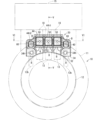
端子台の適用例について説明する。図1は端子台20の適用例を示す概略正面図である。端子台20は、第1機器10のケース11に固定される。端子台20に導電部材13、18がボルトBによって締結固定される。これにより、導電部材13と導電部材18とが電気的かつ機械的に接続される。導電部材13は、第1機器10から延びる部材であることが考えられる。導電部材18は、第2機器15から延びる部材であることが考えられる。よって、端子台20は、第1機器10と第2機器15とを電気的に接続するための部分として利用され得る。 <Application example of terminal block>
An application example of the terminal block will be described. FIG. 1 is a schematic front view showing an application example of theterminal block 20. FIG. The terminal block 20 is fixed to the case 11 of the first device 10 . The conductive members 13 and 18 are fastened and fixed to the terminal block 20 with bolts B. As shown in FIG. Thereby, the conductive member 13 and the conductive member 18 are electrically and mechanically connected. Conductive member 13 may be a member extending from first device 10 . Conductive member 18 may be a member extending from second device 15 . Therefore, the terminal block 20 can be used as a part for electrically connecting the first device 10 and the second device 15 .
端子台の適用例について説明する。図1は端子台20の適用例を示す概略正面図である。端子台20は、第1機器10のケース11に固定される。端子台20に導電部材13、18がボルトBによって締結固定される。これにより、導電部材13と導電部材18とが電気的かつ機械的に接続される。導電部材13は、第1機器10から延びる部材であることが考えられる。導電部材18は、第2機器15から延びる部材であることが考えられる。よって、端子台20は、第1機器10と第2機器15とを電気的に接続するための部分として利用され得る。 <Application example of terminal block>
An application example of the terminal block will be described. FIG. 1 is a schematic front view showing an application example of the
第1機器10は、例えば、可動部品を有する機械的な機器である。例えば、第1機器10は、ケース11、電機子12及び界磁を備える回転電機である。図1では、筒状のケース11内に、ステータとしての電機子12が固定されている例が示される。界磁は、ロータとして電機子12内に配置されている。電機子12が発生させる磁界によって界磁が回転し、又は、界磁の回転によって電機子12が起電力を発生させる。第1機器10は、当該第1機器10を冷却するための冷媒14を備える。冷媒14は、例えば、ケース11の内周面と外周面との間に形成された冷媒流路11f(図5参照)を流れる液体である。冷媒流路11fを流れる液体は例えば水である。ケース11内に冷媒が封入されていてもよい。この場合の液体は、例えば、潤滑オイルであってもよい。
The first device 10 is, for example, a mechanical device having movable parts. For example, the first device 10 is a rotating electrical machine that includes a case 11, an armature 12, and a magnetic field. FIG. 1 shows an example in which an armature 12 as a stator is fixed inside a tubular case 11 . The field is arranged in the armature 12 as a rotor. The magnetic field generated by the armature 12 rotates the magnetic field, or the rotation of the magnetic field causes the armature 12 to generate an electromotive force. The first device 10 includes coolant 14 for cooling the first device 10 . The coolant 14 is, for example, a liquid that flows through a coolant channel 11f (see FIG. 5) formed between the inner peripheral surface and the outer peripheral surface of the case 11 . The liquid flowing through the coolant channel 11f is, for example, water. A refrigerant may be enclosed in the case 11 . The liquid in this case may be, for example, lubricating oil.
第2機器15は、信号処理回路を有する電気機器である。例えば、第2機器15は、第1機器10を制御する制御回路を有する電気機器である。より具体的には、第2機器15は、回転電機である第1機器10を駆動制御するインバータ機器である。第2機器15は、第1機器10のケース11に対してボルト固定等によって一体化されてもよい。このように、機械的な機器である第1機器10と、当該第1機器を制御する制御回路を有する第2機器とが一体化されたユニットは、機電一体型ユニットと称されてもよい。
The second device 15 is an electrical device having a signal processing circuit. For example, the second device 15 is an electrical device having control circuitry for controlling the first device 10 . More specifically, the second device 15 is an inverter device that drives and controls the first device 10, which is a rotating electrical machine. The second device 15 may be integrated with the case 11 of the first device 10 by bolting or the like. A unit in which the first device 10, which is a mechanical device, and the second device having a control circuit for controlling the first device are thus integrated may be referred to as an electromechanical integrated unit.
第1機器10の導電部材13は、電機子12のコイル線に接続されたバスバであることが想定される。第2機器15の導電部材18は、第2機器15のインバータ回路の出力端に接続されたバスバであることが想定される。バスバは、銅、銅合金等の金属板材によって形成された細長板状部材であり、ボルトBの締結固定のための孔を有している。本実施形態では、第1機器10が3相交流モータとして使用可能な回転電機であることが想定されている。このため、電機子12から3つの導電部材13が間隔をあけて並列状態でケース11に向って延びている。また、第2機器15から3つの導電部材18が、前記3つの導電部材13と同じ間隔で、並列状態で延出している。端子台20がケース11の開口側の端面に固定される。ケース11への端子台20の固定は、例えば、ボルトBの締結によってなされる。端子台20上において、3本の導電部材13のそれぞれの端部が、対応する3本の導電部材18の端部に重ね合わされる。この状態で、ボルトBが導電部材13、18を貫通して、端子台20のナット部50に螺合締結される。これにより、導電部材13、18が互いに接触した状態で端子台20上の一定位置に固定されると共に、導電部材13、18が電気的に接続された状態となる。なお、ケース11の開口は蓋部によって閉じられる。
It is assumed that the conductive member 13 of the first device 10 is a busbar connected to the coil wire of the armature 12 . It is assumed that the conductive member 18 of the second device 15 is a busbar connected to the output terminal of the inverter circuit of the second device 15 . The bus bar is an elongated plate-shaped member made of a metal plate material such as copper or copper alloy, and has holes for fastening and fixing bolts B thereon. In this embodiment, it is assumed that the first device 10 is a rotating electric machine that can be used as a three-phase AC motor. For this reason, three conductive members 13 extend from the armature 12 toward the case 11 in parallel with a space therebetween. Also, three conductive members 18 extend from the second device 15 in parallel at the same intervals as the three conductive members 13 . A terminal block 20 is fixed to the end face of the case 11 on the opening side. The terminal block 20 is fixed to the case 11 by fastening bolts B, for example. On the terminal block 20 , the ends of the three conductive members 13 are overlapped with the ends of the corresponding three conductive members 18 . In this state, the bolt B passes through the conductive members 13 and 18 and is screwed into the nut portion 50 of the terminal block 20 . As a result, the conductive members 13 and 18 are fixed at a fixed position on the terminal block 20 while being in contact with each other, and the conductive members 13 and 18 are electrically connected. The opening of the case 11 is closed by a lid.
なお、端子台20による接続される導電部材13、18の数は、任意である。また、接続対象となる導電部材の一方が、ボルトBによる締結固定前の状態で、端子台20に一体的に支持されていてもよい。
The number of conductive members 13 and 18 connected by the terminal block 20 is arbitrary. Also, one of the conductive members to be connected may be integrally supported by the terminal block 20 before being fastened and fixed by the bolts B. As shown in FIG.
<端子台の全体構成について>
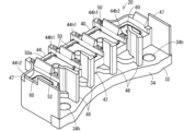
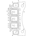
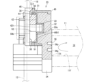
端子台20の全体構成について説明する。図2は端子台20を示す斜視図である。図3は端子台20を示す分解斜視図である。図3ではヒートシンク30が絶縁部材40から離れ、かつ、複数のナット部50のうちの1つが絶縁部材40から離れている状態が示されている。図4はヒートシンク30を示す正面図である。図4においてリブ38、39の位置をナット部50との関係で説明するため、ナット部50が図示されている。図5は図1におけるV-V線断面図であり、図6は図1におけるVI-VI線断面図である。 <Regarding the overall configuration of the terminal block>
An overall configuration of theterminal block 20 will be described. FIG. 2 is a perspective view showing the terminal block 20. FIG. FIG. 3 is an exploded perspective view showing the terminal block 20. FIG. FIG. 3 shows a state in which the heat sink 30 is separated from the insulating member 40 and one of the plurality of nut portions 50 is separated from the insulating member 40 . FIG. 4 is a front view showing the heat sink 30. FIG. In order to explain the positions of the ribs 38 and 39 in relation to the nut portion 50 in FIG. 4, the nut portion 50 is illustrated. 5 is a sectional view taken along line VV in FIG. 1, and FIG. 6 is a sectional view taken along line VI-VI in FIG.
端子台20の全体構成について説明する。図2は端子台20を示す斜視図である。図3は端子台20を示す分解斜視図である。図3ではヒートシンク30が絶縁部材40から離れ、かつ、複数のナット部50のうちの1つが絶縁部材40から離れている状態が示されている。図4はヒートシンク30を示す正面図である。図4においてリブ38、39の位置をナット部50との関係で説明するため、ナット部50が図示されている。図5は図1におけるV-V線断面図であり、図6は図1におけるVI-VI線断面図である。 <Regarding the overall configuration of the terminal block>
An overall configuration of the
端子台20は、ナット部50と、ヒートシンク30と、絶縁部材40とを備える。
The terminal block 20 includes a nut portion 50, a heat sink 30, and an insulating member 40.
ナット部50は、ボルトBが螺合されるナットである。ナット部50は、例えば、ネジ孔52が形成された部材である。ナット部50は、絶縁部材40によって回転止状態で保持可能なように非円形状の外周形状を有しているとよい。例えば、ナット部50は、ボルトBの軸方向(つまり、ネジ孔52の軸方向)に沿って見て、複数の辺51によって囲まれる形状である。複数の辺51は、例えば、直線である。ナット部50の周方向において隣合う辺51は、曲線をなして連なっていてもよい。本実施形態では、ナット部50は、ボルトBの軸方向に沿って見て四角い形状、より具体的には、一対の対辺が他の一対の対辺よりも長い長方形状に形成されている。ナット部50は、その他の多角形状、例えば、六角形状に形成されることも考えられる。
The nut portion 50 is a nut to which the bolt B is screwed. The nut portion 50 is, for example, a member in which a screw hole 52 is formed. The nut portion 50 preferably has a non-circular outer peripheral shape so that it can be held in a non-rotating state by the insulating member 40 . For example, the nut portion 50 has a shape surrounded by a plurality of sides 51 when viewed along the axial direction of the bolt B (that is, the axial direction of the screw hole 52). The multiple sides 51 are, for example, straight lines. Sides 51 that are adjacent in the circumferential direction of the nut portion 50 may form a curved line. In this embodiment, the nut portion 50 is formed in a square shape when viewed along the axial direction of the bolt B, more specifically, in a rectangular shape with a pair of opposite sides longer than the other pair of opposite sides. It is also conceivable that the nut portion 50 is formed in other polygonal shapes, such as hexagonal shapes.
ナット部50の厚み方向両側の一対の主面50a、50bは、互いに反対側を向き、かつ、互いに平行な面である。一方の主面50aは、絶縁部材40のナット収容凹部44h1の底面に面接触することができる。他方の主面50bは、導電部材13又は導電部材18に面接触することができる。
A pair of main surfaces 50a and 50b on both sides in the thickness direction of the nut portion 50 are surfaces facing opposite sides and parallel to each other. One main surface 50a can come into surface contact with the bottom surface of the nut accommodating recess 44h1 of the insulating member 40. As shown in FIG. The other main surface 50b can be in surface contact with the conductive member 13 or the conductive member 18 .
本実施形態では、端子台20は、導電部材13、18の接続数に応じて、3つのナット部50を備える。ナット部50の数は、締結対象となる導電部材13、18の接続数に応じて任意の数設けられる。端子台20は、他のナット部60を備えていてもよい。
In this embodiment, the terminal block 20 has three nut portions 50 corresponding to the number of connections of the conductive members 13 and 18 . An arbitrary number of nut portions 50 is provided according to the number of connections of the conductive members 13 and 18 to be fastened. The terminal block 20 may have another nut portion 60 .
ヒートシンク30は、熱伝導材によって形成される。熱伝導材は、絶縁部材40よりも熱伝導性が良好な材料であり、例えば、アルミニウム、アルミニウム合金等の金属である。ヒートシンク30は、例えば、金属の切削加工によって一体形成された部品である。ヒートシンク30は、金型加工、プレス加工等によって形成されてもよい。ヒートシンク30は、ナット支持ベース部32と、固定ベース部34とを含む。
The heat sink 30 is made of a thermally conductive material. The thermally conductive material is a material having better thermal conductivity than the insulating member 40, and is, for example, a metal such as aluminum or an aluminum alloy. The heat sink 30 is, for example, a component integrally formed by cutting metal. The heat sink 30 may be formed by die processing, press processing, or the like. Heat sink 30 includes a nut support base portion 32 and a fixed base portion 34 .
ナット支持ベース部32は、細長い板状部分に形成されている。ナット支持ベース部32の一方の主面上に絶縁部材40を介してナット部50及びナット部60が支持される。本実施形態では、3つのナット部50がナット支持ベース部32の長手方向中間部に位置し、2つのナット部50がナット支持ベース部32の長手方向両端部に位置する。ナット支持ベース部32の一主面上に、ボルト逃し穴33が形成されている。ボルト逃し穴33は、有底穴であり、各ナット部50及び各ナット部60のネジ孔の延長上に位置している。
The nut support base portion 32 is formed in an elongated plate-like portion. A nut portion 50 and a nut portion 60 are supported on one main surface of the nut support base portion 32 via an insulating member 40 . In the present embodiment, three nut portions 50 are positioned in the middle portion of the nut support base portion 32 in the longitudinal direction, and two nut portions 50 are positioned at both longitudinal end portions of the nut support base portion 32 . A bolt relief hole 33 is formed on one main surface of the nut support base portion 32 . The bolt escape hole 33 is a hole with a bottom, and is located on the extension of the screw holes of each nut portion 50 and each nut portion 60 .
固定ベース部34は、ナット支持ベース部32の短手方向一側から当該ナット支持ベース部32の外側に向けて延出する細長い板状部分である。本実施形態では、固定ベース部34は、ナット支持ベース部32よりも薄く、固定ベース部34とナット支持ベース部32との間に段差が形成されている。固定ベース部34には、固定孔34hが形成されている。本実施形態では、固定ベース部34の長手方向両端に固定孔34hが形成されている。ボルトBが本固定孔34hに挿通された状態で、ケース11に形成されたネジ孔に螺合締結されることで、端子台20がケース11に固定される。ナット支持ベース部32に対する固定ベース部34の延出位置は任意である。例えば、ナット支持ベース部32の長手方向両端の外側延長上に、固定孔を有する固定ベース部が延出してもよい。
The fixed base portion 34 is an elongated plate-like portion extending from one side of the nut support base portion 32 in the short direction toward the outside of the nut support base portion 32 . In this embodiment, the fixed base portion 34 is thinner than the nut support base portion 32 and a step is formed between the fixed base portion 34 and the nut support base portion 32 . A fixing hole 34 h is formed in the fixing base portion 34 . In this embodiment, fixing holes 34h are formed at both longitudinal ends of the fixing base portion 34. As shown in FIG. The terminal block 20 is fixed to the case 11 by screwing the bolt B into a screw hole formed in the case 11 while the bolt B is inserted through the main fixing hole 34h. The extension position of the fixed base portion 34 with respect to the nut support base portion 32 is arbitrary. For example, on the outer extension of both longitudinal ends of the nut support base portion 32, a fixing base portion having a fixing hole may extend.
ヒートシンク30は、第1機器10を冷却する冷媒14が接触する放熱部36を有する。放熱部36は、端子台20をケース11に固定した状態で、ケース11側を向く部分に形成されている。例えば、ケース11に形成された冷媒流路11fが、ケース11の開口端面のうち端子台20が取付けられる部分で開口している。ヒートシンク30は、当該開口11hを塞ぐようにケース11に固定される。ケース11のうち開口11hを塞ぐ部分に放熱部36が形成される。本実施形態では、ヒートシンク30のうちナット部50とは反対側を向く他方の主面に放熱部36が形成される。本実施形態では、ヒートシンク30の他方の主面に、ケース11の開口端面に沿う弧状の溝36gが形成されている。放熱部36は、当該溝36gの表面を含む構成である。冷媒14が溝36g内に入り込むことによって、冷媒14の流れがナット部50の近づくことができ、かつ、冷媒14とヒートシンク30との接触面積が増える。これにより、ヒートシンク30の熱が効果的に冷媒14に伝わることができる。また、本実施形態では、溝36gの底部に、弧状凸部36pが形成されている。放熱部36は、当該弧状凸部36pの表面を含む。この弧状凸部36pによって、冷媒14とヒートシンク30との接触面積がさらに増え、ヒートシンク30の熱がより効果的に冷媒14に伝わることができる。
The heat sink 30 has a heat radiation portion 36 with which the coolant 14 that cools the first device 10 contacts. The heat radiation portion 36 is formed in a portion facing the case 11 side when the terminal block 20 is fixed to the case 11 . For example, the coolant channel 11f formed in the case 11 opens at a portion of the open end surface of the case 11 where the terminal block 20 is attached. The heat sink 30 is fixed to the case 11 so as to close the opening 11h. A heat radiating portion 36 is formed in a portion of the case 11 that closes the opening 11h. In this embodiment, the heat radiating portion 36 is formed on the other main surface of the heat sink 30 facing away from the nut portion 50 . In this embodiment, the other main surface of the heat sink 30 is formed with an arc-shaped groove 36g along the open end surface of the case 11. As shown in FIG. The heat radiation portion 36 is configured to include the surface of the groove 36g. As the coolant 14 enters the groove 36g, the coolant 14 can flow closer to the nut portion 50 and the contact area between the coolant 14 and the heat sink 30 increases. Thereby, the heat of the heat sink 30 can be effectively transferred to the coolant 14 . Further, in the present embodiment, an arcuate protrusion 36p is formed at the bottom of the groove 36g. The heat radiating portion 36 includes the surface of the arc-shaped convex portion 36p. The arc-shaped projections 36 p further increase the contact area between the coolant 14 and the heat sink 30 , and the heat of the heat sink 30 can be transmitted to the coolant 14 more effectively.
放熱部36が上記構成であることは必須ではない。例えば、放熱部は、ヒートシンク30内を貫通しかつ冷媒が流れる貫通孔であってもよい。ヒートシンク30において、冷媒14が接触する部分があれば、当該部分を放熱部とすることができる。放熱部36は、ケース11内に封入されたオイルによって冷却される部分であってもよい。
It is not essential that the heat radiating section 36 has the above configuration. For example, the heat radiating portion may be a through hole that passes through the heat sink 30 and through which a coolant flows. If the heat sink 30 has a portion with which the coolant 14 contacts, the portion can be used as a heat radiation portion. The heat radiating portion 36 may be a portion cooled by oil enclosed in the case 11 .
ヒートシンク30は、ナット部50の周囲に位置するリブ38、39を含む。リブ38、39は、ナット部50の周囲に位置するように、ナット支持ベース部32の一方主面から突出するように形成される。リブ38、39の具体的構成例については、後にさらに詳述する。
The heat sink 30 includes ribs 38 , 39 positioned around the nut portion 50 . Ribs 38 and 39 are formed to protrude from one main surface of nut support base portion 32 so as to be positioned around nut portion 50 . A specific configuration example of the ribs 38 and 39 will be described in more detail later.
絶縁部材40は、ナット部50とヒートシンク30とを電気的に絶縁する部材である。絶縁部材40は、例えば、樹脂によって金型一体成形された部材である。絶縁部材40は、例えば、ヒートシンク30をインサート部として金型成形された部材である。
The insulating member 40 is a member that electrically insulates the nut portion 50 and the heat sink 30 from each other. The insulating member 40 is, for example, a member integrally molded with a resin. The insulating member 40 is, for example, a member that is molded using the heat sink 30 as an insert.
絶縁部材40は、第1絶縁部42と、第2絶縁部44と、仕切部46、47とを含む。第1絶縁部42はナット部50とヒートシンク30との間に介在する部分である。第2絶縁部44はナット部50の周囲を囲む部分である。第2絶縁部44はさらにナット部60を囲む部分も含む。仕切部46は、ナット部50又は当該ナット部50に接続される導電部材13、18を他の部分から仕切る部分であり、仕切部47は、ナット部60及び当該ナット部に接続される導電部材13bを他の部分から仕切る部分である。
The insulating member 40 includes a first insulating portion 42 , a second insulating portion 44 , and partitions 46 and 47 . The first insulating portion 42 is a portion interposed between the nut portion 50 and the heat sink 30 . The second insulating portion 44 is a portion surrounding the nut portion 50 . The second insulating portion 44 also includes a portion surrounding the nut portion 60 . The partition portion 46 is a portion that partitions the nut portion 50 or the conductive members 13 and 18 connected to the nut portion 50 from other portions, and the partition portion 47 is a portion that separates the nut portion 60 and the conductive member connected to the nut portion. 13b from other parts.
より具体的には、第1絶縁部42は、ナット支持ベース部32の一方主面上に全体的に広がる細長板状に形成されている。ナット部50、60は、当該第1絶縁部42上に配置されるため、ナット部50、60は、第1絶縁部42によってヒートシンク30に対して電気的に絶縁した状態に保たれる。第1絶縁部42は、ナット支持ベース部32の外周囲の一部又は全部を覆っていてもよい。なお、本実施形態では、固定ベース部34の大部分は絶縁部材40から露出している。
More specifically, the first insulating portion 42 is formed in an elongated plate shape that extends entirely on one main surface of the nut support base portion 32 . Since the nut portions 50 and 60 are arranged on the first insulating portion 42 , the nut portions 50 and 60 are kept electrically insulated from the heat sink 30 by the first insulating portion 42 . The first insulating portion 42 may cover part or all of the outer periphery of the nut support base portion 32 . It should be noted that most of the fixed base portion 34 is exposed from the insulating member 40 in this embodiment.
第1絶縁部42のうちナット部50、60が配置される側の面に、ボルト逃し穴42hが形成されている。ボルト逃し穴42hは、上記ボルト逃し穴33に対応する位置に形成された有底穴であり、各ナット部50及び各ナット部60のネジ孔の延長上に位置している。
A bolt relief hole 42h is formed in the surface of the first insulating portion 42 on which the nut portions 50 and 60 are arranged. The bolt relief hole 42h is a bottomed hole formed at a position corresponding to the bolt relief hole 33, and is located on the extension of the screw holes of the nut portions 50 and 60. As shown in FIG.
第2絶縁部44は、第1絶縁部42のうちナット部50、60が配置される側の面から、当該ナット部50、60の周囲を囲うように突出している。つまり、絶縁部材40には、ナット部50を、回転規制した状態で、一定位置で収容可能なナット収容凹部44h1が形成されている。ナット収容凹部44h1の底部を構成する部分が第1絶縁部42であり、ナット収容凹部44h1の周壁を構成する部分が第2絶縁部44である。また、本実施形態では、絶縁部材40には、ナット部60を、回転規制した状態で、一定位置で収容可能なナット収容凹部44h2が形成されている。ナット収容凹部44h2の底部を構成する部分が第1絶縁部42であり、ナット収容凹部44h2の周壁を構成する部分が第2絶縁部44である。
The second insulating portion 44 protrudes from the surface of the first insulating portion 42 on which the nut portions 50 and 60 are arranged so as to surround the nut portions 50 and 60 . That is, the insulating member 40 is formed with a nut accommodating recess 44h1 that can accommodate the nut portion 50 at a fixed position while the nut portion 50 is restricted from rotating. A portion forming the bottom of the nut accommodating recess 44h1 is the first insulating portion 42, and a portion forming the peripheral wall of the nut accommodating recess 44h1 is the second insulating portion 44. As shown in FIG. Further, in the present embodiment, the insulating member 40 is formed with a nut accommodating recess 44h2 that can accommodate the nut portion 60 at a fixed position while the nut portion 60 is restricted from rotating. The portion forming the bottom of the nut accommodating recess 44h2 is the first insulating portion 42, and the portion forming the peripheral wall of the nut accommodating recess 44h2 is the second insulating portion 44. As shown in FIG.
本実施形態では、3つのナット部50に対応して3つのナット収容凹部44h1が、絶縁部材40に間隔をあけて直線状に並ぶように形成される。2つのナット収容凹部44h2が、3つのナット収容凹部44h1が並ぶ方向において、当該3つのナット収容凹部44h1の外側に形成される。このため、3つのナット部50のそれぞれが、3つのナット部50に収容されることで、間隔をあけて直線状に並ぶように回転規制された状態で保持される。また、2つのナット部60が、3つのナット部50が並ぶ方向において、当該3つのナット部50の外側に回転規制された状態で保持される。ナット部50、60が別々に、ナット収容凹部44h1、44h2に収容されるため、ナット部50、60は、絶縁部材40によって相互に電気的に絶縁された状態に保たれる。
In this embodiment, three nut accommodating recesses 44h1 corresponding to the three nut portions 50 are formed in the insulating member 40 so as to be linearly spaced apart. Two nut housing recesses 44h2 are formed outside the three nut housing recesses 44h1 in the direction in which the three nut housing recesses 44h1 are arranged. For this reason, each of the three nut portions 50 is accommodated in the three nut portions 50, so that the nut portions 50 are held in a state in which rotation is restricted so as to be arranged in a straight line with an interval therebetween. In addition, the two nut portions 60 are held in a state in which rotation is restricted outside the three nut portions 50 in the direction in which the three nut portions 50 are arranged. Since the nut portions 50 and 60 are individually housed in the nut housing recesses 44h1 and 44h2, the nut portions 50 and 60 are kept electrically insulated from each other by the insulating member 40. FIG.
なお、ナット部50、60をインサート部として絶縁部材40が金型成形されることによって上記ナット収容凹部44h1、44h2が形成されてもよい。または、ナット部50、60とは別に、ナット収容凹部44h1、44h2の形状を含む絶縁部材40が金型成形され、当該ナット収容凹部44h1、44h2にナット部50、60が嵌め込まれてもよい。
The nut accommodating recesses 44h1 and 44h2 may be formed by molding the insulating member 40 using the nut portions 50 and 60 as insert portions. Alternatively, the insulating member 40 including the shapes of the nut accommodating recesses 44h1 and 44h2 may be molded separately from the nut parts 50 and 60, and the nut parts 50 and 60 may be fitted into the nut accommodating recesses 44h1 and 44h2.
また、ナット部50、60及びナット収容凹部44h1、44h2の数、位置は、接続対象となる導電部材13、13b、18の数、配置等に応じて適宜変更され得る。
Also, the number and positions of the nut portions 50 and 60 and the nut housing recesses 44h1 and 44h2 can be appropriately changed according to the number and arrangement of the conductive members 13, 13b and 18 to be connected.
仕切部46は、第1絶縁部42及び第2絶縁部44から、複数のナット部50が並ぶ方向とは交差する方向に延出する部分である。より具体的には、仕切部46は、複数のナット収容凹部44h1の間と、ナット収容凹部44h1とナット収容凹部44h2との間に位置している。仕切部46は、第2絶縁部44よりも第1絶縁部42とは反対側に延出する細長板状部分と、第1絶縁部42及び第2絶縁部44から固定ベース部34側に延出する板状部分とを含む。仕切部46によって、隣合うナット部50、60の関係で、導電部材13、13b、18が接触することが抑制される。
The partition portion 46 is a portion extending from the first insulating portion 42 and the second insulating portion 44 in a direction intersecting the direction in which the plurality of nut portions 50 are arranged. More specifically, the partitions 46 are positioned between the plurality of nut-accommodating recesses 44h1 and between the nut-accommodating recesses 44h1 and 44h2. The partition part 46 has an elongated plate-like part extending from the second insulating part 44 to the side opposite to the first insulating part 42 , and an elongated plate-like part extending from the first insulating part 42 and the second insulating part 44 to the fixed base part 34 side. It includes a plate-shaped portion that comes out. Due to the relationship between the adjacent nut portions 50 and 60, the partition portion 46 prevents the conductive members 13, 13b, and 18 from coming into contact with each other.
仕切部47は、第1絶縁部42及び第2絶縁部44から、複数のナット部50、60が並ぶ方向とは交差する方向に延出する部分である。より具体的には、仕切部47は、複数のナット収容凹部44h1、44h2が並ぶ方向において、両端の仕切部46の外側に位置している。仕切部47は、第2絶縁部44よりも第1絶縁部42とは反対側に延出してナット収容凹部44h2の周りの一部を囲む曲った板状部分と、第1絶縁部42及び第2絶縁部44から固定ベース部34側に延出する板状部分とを含む。仕切部47によって、ナット部60に接続された導電部材13bが周囲の部分に接触することが抑制される。
The partition part 47 is a part extending from the first insulating part 42 and the second insulating part 44 in a direction crossing the direction in which the plurality of nut parts 50 and 60 are arranged. More specifically, the partitions 47 are positioned outside the partitions 46 at both ends in the direction in which the plurality of nut housing recesses 44h1 and 44h2 are arranged. The partition part 47 includes a curved plate-like part extending from the second insulating part 44 to the side opposite to the first insulating part 42 and partially surrounding the nut accommodating recess 44h2, the first insulating part 42 and the first insulating part 42 2 and a plate-like portion extending from the insulating portion 44 toward the fixed base portion 34 side. The partition portion 47 prevents the conductive member 13b connected to the nut portion 60 from coming into contact with the surrounding portion.
仕切部46、47の形状は上記形状に限定されず任意である。仕切部46、47は、必須では無く省略されてもよい。
The shape of the partitions 46 and 47 is not limited to the shape described above and is arbitrary. The partitions 46 and 47 are not essential and may be omitted.
なお、絶縁部材40は、ヒートシンク30をインサート部として金型成形された部材であることは必須ではない。絶縁部材40は、ヒートシンク30とは別に金型成形された後、ヒートシンク30と組合わされた部材であってもよい。絶縁部材40は、複数の樹脂部品の組合せによって構成されていてもよい。この場合において、複数の樹脂部品は、一次成形部と当該一次成形部をインサート部として金型成形された二次成形部との組合せによって構成されていてもよい。一次成形部は、ヒートシンク30をインサート部として金型成形された部分であてもよいし、ヒートシンク30とは別に金型成形されてヒートシンク30と組合わされてもよい。
It should be noted that it is not essential that the insulating member 40 is a member that is molded using the heat sink 30 as an insert. The insulating member 40 may be a member that is molded separately from the heat sink 30 and then combined with the heat sink 30 . The insulating member 40 may be configured by combining a plurality of resin parts. In this case, the plurality of resin parts may be configured by a combination of a primary molded portion and a secondary molded portion molded by using the primary molded portion as an insert portion. The primary molded portion may be a portion that is molded using the heat sink 30 as an insert portion, or may be molded separately from the heat sink 30 and combined with the heat sink 30 .
<リブについて>
リブ38、39の構成例についてより具体的に説明する。 <About ribs>
A configuration example of the ribs 38 and 39 will be described more specifically.
リブ38、39の構成例についてより具体的に説明する。 <About ribs>
A configuration example of the
リブ38、39は、ナット部50の周囲に位置する。リブ38、39は、ナット部50の熱が、絶縁部材40のうちナット部50とリブ38、39との間の部分を介して、当該リブ38、39に伝わる程度の位置に形成されればよく、ナット部50の周囲における位置は特に限定されない。
The ribs 38 , 39 are positioned around the nut portion 50 . If the ribs 38 and 39 are formed at such a position that the heat of the nut portion 50 is transferred to the ribs 38 and 39 through the portion of the insulating member 40 between the nut portion 50 and the ribs 38 and 39. Well, the position around the nut portion 50 is not particularly limited.
例えば、ナット部50のうちの少なくとも1つにおいて、リブ38、39は、当該ナット部50を囲む複数(本実施形態では4つ)の辺51の全てに対応する位置に設けられてもよい。本実施形態では、複数のナット部50の全てにおいて、リブ38、39がナット部50を囲む複数の辺51の全てに対応する位置に設けられる。
For example, in at least one of the nut portions 50 , the ribs 38 and 39 may be provided at positions corresponding to all of the multiple (four in this embodiment) sides 51 surrounding the nut portion 50 . In this embodiment, the ribs 38 and 39 are provided at positions corresponding to all of the sides 51 surrounding the nut portion 50 on all of the plurality of nut portions 50 .
複数(本実施形態では、3つ)のナット部50との関係でリブ38、39の位置を説明する。本実施形態では、複数のナット部50が互いに離間しつつ並設されており、当該並設された複数のナット部50によってナット群50Gが構成されているとする。複数のナット部50のそれぞれの複数の辺51のうち、ナット群50Gの外周に位置する全ての辺51に対応する位置に、リブ38が設けられている。このため、ナット群50Gの外周において、リブ38をなるべく長くなるように配置することができる。これにより、ナット群50Gの熱が効果的にリブ38に伝わることができる。
The positions of the ribs 38 and 39 will be described in relation to the plurality (three in this embodiment) of the nut portions 50 . In this embodiment, it is assumed that a plurality of nut portions 50 are arranged side by side while being spaced apart from each other, and that a nut group 50G is configured by the plurality of nut portions 50 arranged side by side. Ribs 38 are provided at positions corresponding to all sides 51 positioned on the outer circumference of the nut group 50G among the plurality of sides 51 of each of the plurality of nut portions 50 . Therefore, the ribs 38 can be arranged as long as possible on the outer periphery of the nut group 50G. Thereby, the heat of the nut group 50G can be effectively conducted to the rib 38. As shown in FIG.
また、ナット群50Gにおいて、隣合うナット部50の間の位置にリブ39が設けられる。リブ39は、隣合うナット部50の間で1つだけ設けられる。このため、隣合うナット部50からの熱は、当該隣合うナット部50の間の1つのリブ39に伝わる。なお、隣合うナット部50の間において、隣合うナット部50の一方側及び他方側のそれぞれに近い2つのリブが設けられてもよい。
Further, ribs 39 are provided at positions between adjacent nut portions 50 in the nut group 50G. Only one rib 39 is provided between adjacent nut portions 50 . Therefore, the heat from adjacent nut portions 50 is transferred to one rib 39 between the adjacent nut portions 50 . In addition, between the adjacent nut portions 50 , two ribs may be provided near one side and the other side of the adjacent nut portions 50 .
リブ38、39は、第1絶縁部42の一方主面から突出する細長い板状に形成されている。ボルトBの軸方向に沿って見て、リブ38、39は、ナット部50の辺51に沿って延びるように形成されている。換言すると、ボルトBの軸方向に沿って見て、リブ38、39は、ナット部50の辺51に対して等距離を保ちつつ直線状に延在している。
The ribs 38 and 39 are formed in elongated plate shapes protruding from one main surface of the first insulating portion 42 . The ribs 38 and 39 are formed to extend along the side 51 of the nut portion 50 when viewed along the axial direction of the bolt B. As shown in FIG. In other words, when viewed along the axial direction of the bolt B, the ribs 38 and 39 extend linearly while keeping an equal distance from the side 51 of the nut portion 50 .
ナット部50の各辺51に対応する外向き側面51fは、ボルトBの軸方向に対して直交する外向き面である。リブ38、39は、外向き側面51fに対して間隔をあけて対向している。ナット部50の外向き側面51fと、リブ38、39のうちのナット部50側の側面との間には、等幅の隙間が形成されている。
An outward side surface 51f corresponding to each side 51 of the nut portion 50 is an outward surface orthogonal to the axial direction of the bolt B. The ribs 38, 39 face the outward side surface 51f with a gap therebetween. A gap of equal width is formed between the outward side surface 51f of the nut portion 50 and the side surface of the ribs 38 and 39 on the nut portion 50 side.
各辺51に対応するリブ38、39は、相互に分離している。例えば、リブ38は、複数の辺のうち互いに角度(本実施形態では90゜)をなして隣合う辺51に対応して設けられた第1隣接リブ38aと第2隣接リブ38bとを含む。図4において、そのように隣合う関係となる第1隣接リブ38aと第2隣接リブ38bの一例が図示される。第1隣接リブ38aと第2隣接リブ38bとの間に隙間Sが形成されている。例えば、第1隣接リブ38aの延長線と第2隣接リブ38bの延長線とが角をなして交わる場合において、その交点に対応する位置に隙間Sが形成されている。
The ribs 38, 39 corresponding to each side 51 are separated from each other. For example, the rib 38 includes a first adjacent rib 38a and a second adjacent rib 38b provided corresponding to adjacent sides 51 forming an angle (90° in this embodiment) with each other among the plurality of sides. FIG. 4 shows an example of such a first adjacent rib 38a and a second adjacent rib 38b. A gap S is formed between the first adjacent rib 38a and the second adjacent rib 38b. For example, when the extension line of the first adjacent rib 38a and the extension line of the second adjacent rib 38b intersect at an angle, the gap S is formed at the position corresponding to the intersection.
第1隣接リブ38aと第2隣接リブ38bとの間に隙間Sが存在するため、第1隣接リブ38aと第2隣接リブ38bとを連続して形成する場合と比較して、第1隣接リブ38aと第2隣接リブ38bとを容易に形成できる。例えば、仮に第1隣接リブ38aと第2隣接リブ38bとが角をなして連なっている場合、第1隣接リブ38aの内向き面と第2隣接リブ38bの内向き面とが連なる形状を加工することとなる。切削加工等によって、面と面とが角をなして連なる入隅形状を加工することは難しいため、面と面とが曲面を介して連なるような形状に加工することが想定される。その場合、曲面となる分、リブがナット部50に近づいてしまう。ここで、リブとナット部50との間には絶縁を確保する上で適切な絶縁距離を確保することが想定されている。このため、上記曲面においてリブがナット部50に近づいてしまう分、辺51に対してリブを遠ざけた位置に設定することとなる。そうすると、ナット部50の熱がリブに伝わり難くなってしまう。
Since the gap S exists between the first adjacent rib 38a and the second adjacent rib 38b, the first adjacent rib 38a and the second adjacent rib 38b are formed continuously. 38a and the second adjacent rib 38b can be easily formed. For example, if the first adjacent rib 38a and the second adjacent rib 38b are connected at an angle, the inward surface of the first adjacent rib 38a and the inward surface of the second adjacent rib 38b are processed to form a continuous shape. It will be done. Since it is difficult to process an internal corner shape in which surfaces form an angle and continue to form an angle by cutting or the like, processing into a shape in which surfaces are connected via a curved surface is assumed. In that case, the rib approaches the nut portion 50 by the curved surface. Here, it is assumed that an appropriate insulation distance is secured between the rib and the nut portion 50 in order to secure insulation. For this reason, the rib is set at a position farther from the side 51 than the rib approaches the nut portion 50 on the curved surface. Then, the heat of the nut part 50 becomes difficult to be transmitted to the rib.
第1隣接リブ38aと第2隣接リブ38bとの間に隙間Sを設けることによって、第1隣接リブ38aと第2隣接リブ38bとを連結する部分の加工上の制約が無くなり、第1隣接リブ38aと第2隣接リブ38bとを望ましいとされる絶縁距離を確保できる範囲で、第1隣接リブ38aと第2隣接リブ38bとを、辺51に近づけて配置することができる。これにより、ナット部50から第1隣接リブ38a及び第2隣接リブ38bへ熱が効果的に伝わる。本実施形態では、リブ38、39は、各辺51に対応して設けられており、隣合うリブ38、39間の全てにおいて隙間Sが設けられている。なお、隣合うリブが角をなして又は曲った部分を介して繋がっていてもよい。
By providing the gap S between the first adjacent rib 38a and the second adjacent rib 38b, there is no restriction on processing of the portion connecting the first adjacent rib 38a and the second adjacent rib 38b, and the first adjacent rib The first adjacent rib 38a and the second adjacent rib 38b can be arranged closer to the side 51 as long as a desired insulating distance can be secured between the rib 38a and the second adjacent rib 38b. Thereby, heat is effectively transferred from the nut portion 50 to the first adjacent rib 38a and the second adjacent rib 38b. In this embodiment, the ribs 38 and 39 are provided corresponding to each side 51, and the gap S is provided between all adjacent ribs 38 and 39. As shown in FIG. In addition, adjacent ribs may be connected via an angular or curved portion.
リブ38、39は、ナット支持ベース部32の一方主面を覆う第1絶縁部42を貫通し、第2絶縁部44に埋った状態となっている。リブ38、39は、ナット収容凹部44h1、44h2内に露出していないし、第2絶縁部44のうち第1絶縁部42とは反対側にも露出していない。つまり、リブ38、39とナット部50との間には、絶縁部材40が介在し、当該絶縁部材40によって、リブ38、39とナット部50との電気的な絶縁がなされている。
The ribs 38 and 39 pass through the first insulating portion 42 covering one main surface of the nut support base portion 32 and are buried in the second insulating portion 44 . The ribs 38 and 39 are not exposed in the nut housing recesses 44h1 and 44h2, nor are they exposed on the side of the second insulating portion 44 opposite to the first insulating portion 42. As shown in FIG. That is, the insulating member 40 is interposed between the ribs 38 , 39 and the nut portion 50 , and electrically insulates the ribs 38 , 39 from the nut portion 50 by the insulating member 40 .
リブ38、39の突出高さは、例えば、ナット部50の表面高さ以下である。より具体的には、ナット支持ベース部32の一方主面に対するリブ38、39の突出高さは、ナット支持ベース部32の一方主面を基準とするナット部50の外側主面の高さ位置と同じかそれ以下である。これにより、ナット部50の周囲において、リブ38、39が当該ナット部50よりも突出し難くなり、ナット部50に対する導電部材13、18の締結固定の妨げとなり難い。なお、ナット部50の間又はナット群50Gの並列方向外側において、リブ38がナット部50を超える高さであってもよい。
The protrusion height of the ribs 38, 39 is, for example, equal to or less than the surface height of the nut portion 50. More specifically, the protrusion height of the ribs 38 and 39 with respect to the one main surface of the nut support base portion 32 is the height position of the outer main surface of the nut portion 50 with the one main surface of the nut support base portion 32 as a reference. is equal to or less than As a result, the ribs 38 and 39 are less likely to protrude from the nut portion 50 around the nut portion 50 , and are less likely to hinder fastening and fixing of the conductive members 13 and 18 to the nut portion 50 . The height of the rib 38 may exceed the nut portion 50 between the nut portions 50 or on the outer side of the nut group 50G in the parallel direction.
リブ38、39の突出高さは、例えば、ナット支持ベース部32の一方主面を基準とするナット部50の内側主面の位置を超えている。換言すれば、ボルトBの軸方向において、リブ38、39とナット部50とが重複する位置関係となっている。これにより、ナット部50の熱がリブ38、39に伝わり易くなる。
The protrusion height of the ribs 38 and 39 exceeds, for example, the position of the inner main surface of the nut portion 50 with one main surface of the nut support base portion 32 as a reference. In other words, in the axial direction of the bolt B, the ribs 38 and 39 and the nut portion 50 overlap each other. As a result, the heat of the nut portion 50 is easily transferred to the ribs 38 and 39 .
<効果等>
以上のように構成された端子台20によると、導電部材13で生じた熱がナット部50からリブ38、39を経由してヒートシンク30に伝わり易い。これにより、端子台20の放熱性を向上させることができる。 <Effects, etc.>
According to theterminal block 20 configured as described above, heat generated in the conductive member 13 is easily transferred from the nut portion 50 to the heat sink 30 via the ribs 38 and 39 . Thereby, the heat dissipation of the terminal block 20 can be improved.
以上のように構成された端子台20によると、導電部材13で生じた熱がナット部50からリブ38、39を経由してヒートシンク30に伝わり易い。これにより、端子台20の放熱性を向上させることができる。 <Effects, etc.>
According to the
特に、上記したような機電一体型ユニットにおいては、機械的な機器である第1機器10と、信号処理回路を有する電気機器である第2機器15とが一体化されて近くに配置される。この場合、例えば、第1機器10と第2機器15とは導電部材13、18を介して接続されるところ、導電部材13、18は短く、かつ、ほとんど外部に露出しない。このため、第1機器10で生じた熱、及び、導電部材13、18を電気が流されることによって生じた熱が、第2機器15に伝わり易くなる可能性がある。このような場合において、伝熱経路又は熱の発生源となり得る導電部材13、18の熱を、端子台20において効率的にヒートシンク30に伝えることができる。これにより、第2機器15に熱が伝わり難くなる。
In particular, in the electromechanical integrated unit as described above, the first device 10, which is a mechanical device, and the second device 15, which is an electrical device having a signal processing circuit, are integrated and placed close to each other. In this case, for example, the first device 10 and the second device 15 are connected via the conductive members 13, 18, which are short and hardly exposed to the outside. Therefore, there is a possibility that the heat generated in the first device 10 and the heat generated by the electricity flowing through the conductive members 13 and 18 are easily transferred to the second device 15 . In such a case, the heat of the conductive members 13 and 18, which can be heat transfer paths or heat sources, can be efficiently transferred to the heat sink 30 at the terminal block 20. FIG. This makes it difficult for heat to be conducted to the second device 15 .
また、導電部材13、18における発熱量を小さくするため、導電部材13、18の断面積を大きくすることも考えられるが、本実施形態では、導電部材13、18の断面積を大きくしなくても、導電部材13、18の熱をヒートシンク30に伝えて冷却することができる。
In order to reduce the amount of heat generated by the conductive members 13 and 18, it is conceivable to increase the cross-sectional areas of the conductive members 13 and 18. Also, the heat of the conductive members 13 and 18 can be transferred to the heat sink 30 for cooling.
また、リブ38、39は、ナット部50を囲む複数の辺51の全てに対応する位置に設けられるため、ナット部50の熱が効果的にヒートシンク30に伝わる。
Also, since the ribs 38 and 39 are provided at positions corresponding to all of the multiple sides 51 surrounding the nut portion 50 , the heat of the nut portion 50 is effectively transmitted to the heat sink 30 .
また、複数のナット部50のそれぞれの辺のうち、ナット群50Gの外周に位置する全ての辺51に対応する位置に、リブ38が設けられるため、この点からも、ナット部50の熱が効果的にヒートシンク30に伝わる。
In addition, among the sides of the plurality of nut portions 50, the ribs 38 are provided at positions corresponding to all the sides 51 located on the outer periphery of the nut group 50G. It is effectively transmitted to the heat sink 30.
この場合において、複数のナット部50の間に位置するリブ39によっても、ナット部50の熱が効果的にヒートシンク30に伝わる。
In this case, the heat of the nut portions 50 is effectively transmitted to the heat sink 30 also by the ribs 39 positioned between the plurality of nut portions 50 .
また、リブ38、39は、ナット部50の辺51に沿って延びるように形成されている。このため、例えば、リブ38、39は、ナット部50に対して好ましい絶縁距離を保ちつつ、当該ナット部50に対してなるべく近いに位置することができる。これにより、絶縁性能を保ちつつ、ナット部50の熱が効果的にヒートシンク30に伝わるようにすることができる。
Also, the ribs 38 and 39 are formed to extend along the side 51 of the nut portion 50 . Therefore, for example, the ribs 38 and 39 can be positioned as close to the nut portion 50 as possible while maintaining a preferable insulating distance from the nut portion 50 . As a result, the heat of the nut portion 50 can be effectively transmitted to the heat sink 30 while maintaining insulation performance.
また、リブ38、39は、ナット部50の外向き側面51fの少なくとも1つに間隔を空けて対向するため、当該外向き側面51fから絶縁部材40を介して当該ナット部50の対向面に熱が伝わり易く、ナット部50の熱が効果的にヒートシンク30に伝わる。
In addition, since the ribs 38 and 39 face at least one of the outward side surfaces 51f of the nut portion 50 with a space therebetween, heat is transferred from the outward side surface 51f to the facing surface of the nut portion 50 via the insulating member 40. is easily transmitted, and the heat of the nut portion 50 is effectively transmitted to the heat sink 30. - 特許庁
また、隣合うリブ38、39の間に隙間Sが設けられるため、例えば、隣合うリブを連続して形成する場合の加工上の制約を無くすることができる。これにより、リブ38、39とナット部50との間に絶縁距離を保ちつつ、リブ38、39をなるべくナット部50に近づけて配置する形状を加工し易い。
In addition, since the gap S is provided between the adjacent ribs 38 and 39, it is possible to eliminate restrictions on processing when forming adjacent ribs continuously, for example. Thereby, it is easy to process a shape in which the ribs 38 and 39 are arranged as close to the nut portion 50 as possible while maintaining an insulation distance between the ribs 38 and 39 and the nut portion 50 .
また、リブ38、39の突出高さは、ナット部50の表面高さ以下であるため、ナット部50に締結固定される導電部材13、18がリブ38、39に干渉し難くなる。
Also, since the protrusion height of the ribs 38 and 39 is equal to or less than the surface height of the nut portion 50 , the conductive members 13 and 18 fastened and fixed to the nut portion 50 are less likely to interfere with the ribs 38 and 39 .
また、絶縁部材40によってナット部50とヒートシンク30とを絶縁し、かつ、ナット部50を一定位置及び一定姿勢(つまり回転規制した状態)で保持する構成において、リブ38、39が第2絶縁部44に埋った状態となっている。このため、ナット部50の外周側にリブ38、39が配置され、ナット部50の熱がリブ38、39を経由してヒートシンク30に伝わり易い。
In addition, in a configuration in which the nut portion 50 and the heat sink 30 are insulated by the insulating member 40 and the nut portion 50 is held in a fixed position and a fixed posture (that is, in a state where rotation is restricted), the ribs 38 and 39 are the second insulating portion. It is buried in 44. Therefore, the ribs 38 and 39 are arranged on the outer peripheral side of the nut portion 50 , and the heat of the nut portion 50 is easily transferred to the heat sink 30 via the ribs 38 and 39 .
[変形例]
なお、上記実施形態において、端子台20は、第1機器10の導電部材13と、当該第1機器10に一体化された第2機器15の導電部材18とを接続する必要は無い。第1機器10とは離れた場所の機器から延びる導電部材と第1機器10の導電部材13とを接続してもよい。 [Modification]
In the above embodiment, theterminal block 20 does not need to connect the conductive member 13 of the first device 10 and the conductive member 18 of the second device 15 integrated with the first device 10 . A conductive member extending from a device remote from the first device 10 may be connected to the conductive member 13 of the first device 10 .
なお、上記実施形態において、端子台20は、第1機器10の導電部材13と、当該第1機器10に一体化された第2機器15の導電部材18とを接続する必要は無い。第1機器10とは離れた場所の機器から延びる導電部材と第1機器10の導電部材13とを接続してもよい。 [Modification]
In the above embodiment, the
なお、上記実施形態及び各変形例で説明した各構成は、相互に矛盾しない限り適宜組合わせることができる。
It should be noted that each configuration described in the above embodiment and each modified example can be appropriately combined as long as they do not contradict each other.
10 第1機器(機器)
11 ケース
11f 冷媒流路
11h 開口
12 電機子
13、13b、18 導電部材
14 冷媒
15 第2機器
20 端子台
30 ヒートシンク
32 ナット支持ベース部
33、42h ボルト逃し穴
34 固定ベース部
34h 固定孔
36 放熱部
36g 溝
36p 弧状凸部
38、39 リブ
38a 第1隣接リブ
38b 第2隣接リブ
40 絶縁部材
42 第1絶縁部
44 第2絶縁部
44h1、44h2 ナット収容凹部
46、47 仕切部
50、60 ナット部
50G ナット群
50a、50b ナット部の主面
51 ナット部の辺
51f 外向き側面
52 ネジ孔
B ボルト
S 隙間 10 first equipment (equipment)
11Case 11f Refrigerant channel 11h Opening 12 Armature 13, 13b, 18 Conductive member 14 Refrigerant 15 Second device 20 Terminal block 30 Heat sink 32 Nut support base 33, 42h Bolt relief hole 34 Fixed base 34h Fixing hole 36 Heat dissipation part 36g groove 36p arc-shaped protrusions 38, 39 rib 38a first adjacent rib 38b second adjacent rib 40 insulating member 42 first insulating portion 44 second insulating portion 44h1, 44h2 nut accommodating recessed portion 46, 47 partitioning portions 50, 60 nut portion 50G Nut group 50a, 50b Main surface 51 of nut portion Side 51f of nut portion Outward side surface 52 Screw hole B Bolt S Gap
11 ケース
11f 冷媒流路
11h 開口
12 電機子
13、13b、18 導電部材
14 冷媒
15 第2機器
20 端子台
30 ヒートシンク
32 ナット支持ベース部
33、42h ボルト逃し穴
34 固定ベース部
34h 固定孔
36 放熱部
36g 溝
36p 弧状凸部
38、39 リブ
38a 第1隣接リブ
38b 第2隣接リブ
40 絶縁部材
42 第1絶縁部
44 第2絶縁部
44h1、44h2 ナット収容凹部
46、47 仕切部
50、60 ナット部
50G ナット群
50a、50b ナット部の主面
51 ナット部の辺
51f 外向き側面
52 ネジ孔
B ボルト
S 隙間 10 first equipment (equipment)
11
Claims (9)
- 機器のケースに固定され、導電部材がボルトによって締結される端子台であって、
前記ボルトが螺合されるナット部と、
前記機器を冷却する冷媒が接触する放熱部を含むヒートシンクと、
前記ナット部と前記ヒートシンクとを電気的に絶縁する絶縁部材と、
を備え、
前記ヒートシンクは、前記ナット部の周囲に位置するリブを含む、端子台。 A terminal block fixed to a case of a device and having conductive members fastened with bolts,
a nut portion to which the bolt is screwed;
a heat sink including a heat radiating portion in contact with a coolant that cools the device;
an insulating member that electrically insulates the nut portion and the heat sink;
with
The terminal block, wherein the heat sink includes ribs positioned around the nut portion. - 請求項1に記載の端子台であって、
前記ナット部は、前記ボルトの軸方向に沿って見て複数の辺で囲まれる形状であり、
前記リブは、前記複数の辺の全てに対応する位置に設けられる、端子台。 The terminal block according to claim 1,
The nut portion has a shape surrounded by a plurality of sides when viewed along the axial direction of the bolt,
The terminal block, wherein the ribs are provided at positions corresponding to all of the plurality of sides. - 請求項1に記載の端子台であって、
前記ナット部は、前記ボルトの軸方向に沿って見て複数の辺で囲まれる形状であり、
前記ナット部を複数備え、
前記複数のナット部が互いに離間しつつ並設されてナット群が構成され、
前記リブは、前記複数のナット部のそれぞれの前記複数の辺のうち、前記ナット群の外周に位置する全ての辺に対応する位置に設けられる、端子台。 The terminal block according to claim 1,
The nut portion has a shape surrounded by a plurality of sides when viewed along the axial direction of the bolt,
A plurality of the nut parts are provided,
A nut group is configured by arranging the plurality of nut portions in parallel while being spaced apart from each other,
The said rib is a terminal block provided in the position corresponding to all the sides|sides located in the outer periphery of the said nut group among these sides|sides of each of these nut parts. - 請求項3に記載の端子台であって、
前記リブは、前記複数のナット部の間の位置に設けられる、端子台。 The terminal block according to claim 3,
The terminal block, wherein the rib is provided at a position between the plurality of nut portions. - 請求項2から請求項4のいずれか1項に記載の端子台であって、
前記リブは、前記ナット部の前記辺に沿って延びるように形成されている、端子台。 The terminal block according to any one of claims 2 to 4,
The terminal block, wherein the rib is formed to extend along the side of the nut portion. - 請求項2から請求項5のいずれか1項に記載の端子台であって、
前記ナット部は、前記複数の辺のそれぞれに対応する複数の外向き側面を含み、
前記リブは、前記複数の外向き側面の少なくとも1つに間隔をあけて対向するように設けられている、端子台。 The terminal block according to any one of claims 2 to 5,
the nut portion includes a plurality of outward side surfaces corresponding to each of the plurality of sides;
The terminal block, wherein the rib is provided so as to face at least one of the plurality of outward side surfaces with a space therebetween. - 請求項2から請求項6のいずれか1項に記載の端子台であって、
前記リブは、前記複数の辺のうち互いに角度をなして隣合う辺に対応して設けられた第1隣接リブと第2隣接リブとを含み、
前記第1隣接リブと前記第2隣接リブとの間に隙間が形成されている、端子台。 The terminal block according to any one of claims 2 to 6,
the ribs include first adjacent ribs and second adjacent ribs provided corresponding to adjacent sides forming an angle with each other among the plurality of sides;
A terminal block, wherein a gap is formed between the first adjacent rib and the second adjacent rib. - 請求項1から請求項7のいずれか1項に記載の端子台であって、
前記リブの突出高さは、前記ナット部の表面高さ以下である、端子台。 The terminal block according to any one of claims 1 to 7,
The terminal block, wherein the protrusion height of the rib is equal to or less than the surface height of the nut portion. - 請求項1から請求項8のいずれか1項に記載の端子台であって、
前記絶縁部材は、前記ナット部と前記ヒートシンクとの間に介在する第1絶縁部と、前記ナット部の周囲を囲む第2絶縁部とを含み、
前記リブが前記第2絶縁部内に埋った状態となっている、端子台。 The terminal block according to any one of claims 1 to 8,
The insulating member includes a first insulating portion interposed between the nut portion and the heat sink, and a second insulating portion surrounding the nut portion,
The terminal block, wherein the rib is embedded in the second insulating portion.
Applications Claiming Priority (2)
| Application Number | Priority Date | Filing Date | Title |
|---|---|---|---|
| JP2021-171746 | 2021-10-20 | ||
| JP2021171746A JP2023061671A (en) | 2021-10-20 | 2021-10-20 | Terminal block |
Publications (1)
| Publication Number | Publication Date |
|---|---|
| WO2023068006A1 true WO2023068006A1 (en) | 2023-04-27 |
Family
ID=86059157
Family Applications (1)
| Application Number | Title | Priority Date | Filing Date |
|---|---|---|---|
| PCT/JP2022/036389 WO2023068006A1 (en) | 2021-10-20 | 2022-09-29 | Terminal block |
Country Status (2)
| Country | Link |
|---|---|
| JP (1) | JP2023061671A (en) |
| WO (1) | WO2023068006A1 (en) |
Citations (3)
| Publication number | Priority date | Publication date | Assignee | Title |
|---|---|---|---|---|
| JP2011187838A (en) * | 2010-03-10 | 2011-09-22 | Shindengen Electric Mfg Co Ltd | Mounting structure of transformer |
| JP2012151038A (en) * | 2011-01-20 | 2012-08-09 | Sumitomo Wiring Syst Ltd | Terminal block and manufacturing method of terminal block |
| JP2017118672A (en) * | 2015-12-24 | 2017-06-29 | 矢崎総業株式会社 | Electric junction box |
-
2021
- 2021-10-20 JP JP2021171746A patent/JP2023061671A/en active Pending
-
2022
- 2022-09-29 WO PCT/JP2022/036389 patent/WO2023068006A1/en unknown
Patent Citations (3)
| Publication number | Priority date | Publication date | Assignee | Title |
|---|---|---|---|---|
| JP2011187838A (en) * | 2010-03-10 | 2011-09-22 | Shindengen Electric Mfg Co Ltd | Mounting structure of transformer |
| JP2012151038A (en) * | 2011-01-20 | 2012-08-09 | Sumitomo Wiring Syst Ltd | Terminal block and manufacturing method of terminal block |
| JP2017118672A (en) * | 2015-12-24 | 2017-06-29 | 矢崎総業株式会社 | Electric junction box |
Also Published As
| Publication number | Publication date |
|---|---|
| JP2023061671A (en) | 2023-05-02 |
Similar Documents
| Publication | Publication Date | Title |
|---|---|---|
| US6704201B2 (en) | Power feed and heat dissipating device for power semiconductor devices | |
| US10332822B2 (en) | Pedestal surface for MOSFET module | |
| EP2495817B1 (en) | Terminal block, motor provided therewith and method of mounting a terminal block | |
| US10727655B2 (en) | Conduction path | |
| CN106796933B (en) | Power supply module and power inverter | |
| JP6409968B2 (en) | Mechanical and electric integrated rotating electrical machine | |
| US20140239755A1 (en) | Rotating electrical machine | |
| US20140239750A1 (en) | Rotating electrical machine | |
| JP6129286B1 (en) | Electric power supply unit integrated rotating electric machine | |
| US10230221B2 (en) | Spout for switchgear, switchgear having spout, and method thereof | |
| US11864362B2 (en) | Power supply device with a heat generating component | |
| JP2019003893A (en) | Terminal board, and electric motor | |
| CN112106455B (en) | Power converter device for vehicle and vehicle | |
| JP6068933B2 (en) | Vehicle motor unit | |
| WO2023068006A1 (en) | Terminal block | |
| US11632013B2 (en) | Control device and motor device that ensure heat dissipation while reducing the size of the motor device | |
| JP7282265B2 (en) | power converter | |
| JP7366082B2 (en) | power converter | |
| JP7069733B2 (en) | Heat dissipation block and power converter | |
| JP6787164B2 (en) | Control device integrated rotary electric machine | |
| JP2019187202A (en) | Motor device | |
| WO2023032844A1 (en) | Power conversion device and drive device | |
| WO2023162051A1 (en) | Power conversion device | |
| CN117413451A (en) | Cooling type heavy current system | |
| CN115474403A (en) | Electronic device and photovoltaic power optimizer |
Legal Events
| Date | Code | Title | Description |
|---|---|---|---|
| 121 | Ep: the epo has been informed by wipo that ep was designated in this application |
Ref document number: 22883314 Country of ref document: EP Kind code of ref document: A1 |