WO2023067811A1 - 電力変換装置、モータ駆動装置および冷凍サイクル適用機器 - Google Patents
電力変換装置、モータ駆動装置および冷凍サイクル適用機器 Download PDFInfo
- Publication number
- WO2023067811A1 WO2023067811A1 PCT/JP2021/039143 JP2021039143W WO2023067811A1 WO 2023067811 A1 WO2023067811 A1 WO 2023067811A1 JP 2021039143 W JP2021039143 W JP 2021039143W WO 2023067811 A1 WO2023067811 A1 WO 2023067811A1
- Authority
- WO
- WIPO (PCT)
- Prior art keywords
- current
- control
- frequency
- motor
- unit
- Prior art date
- Legal status (The legal status is an assumption and is not a legal conclusion. Google has not performed a legal analysis and makes no representation as to the accuracy of the status listed.)
- Ceased
Links
Images





Classifications
-
- H—ELECTRICITY
- H02—GENERATION; CONVERSION OR DISTRIBUTION OF ELECTRIC POWER
- H02P—CONTROL OR REGULATION OF ELECTRIC MOTORS, ELECTRIC GENERATORS OR DYNAMO-ELECTRIC CONVERTERS; CONTROLLING TRANSFORMERS, REACTORS OR CHOKE COILS
- H02P27/00—Arrangements or methods for the control of AC motors characterised by the kind of supply voltage
- H02P27/04—Arrangements or methods for the control of AC motors characterised by the kind of supply voltage using variable-frequency supply voltage, e.g. inverter or converter supply voltage
- H02P27/06—Arrangements or methods for the control of AC motors characterised by the kind of supply voltage using variable-frequency supply voltage, e.g. inverter or converter supply voltage using DC to AC converters or inverters
Definitions
- the present disclosure relates to a power conversion device, a motor drive device, and a refrigeration cycle application device that convert AC power into desired power.
- a device such as a motor control device that controls the operation of an electric motor can reduce power consumption by appropriately compensating for the pulsating component of torque according to the state of the electric motor that drives a single rotary compressor, twin rotary compressor, etc. restrains the increase in Such a technique is disclosed in Patent Document 1.
- the torque ripple component is compensated for the purpose of reducing power consumption.
- the current is unbalanced between the positive side and the negative side of the power supply current, and even-order harmonic components may increase.
- the present disclosure has been made in view of the above, and an object thereof is to obtain a power converter capable of adjusting the control amount of control for reducing power consumption and control for suppressing generation of harmonic components.
- a power conversion device includes a rectification unit that rectifies first AC power supplied from a commercial power supply, and a rectification unit that is connected to an output end of the rectification unit.
- the control device performs current peak control to reduce fluctuations in the amplitude of the current supplied to the motor, and load current control to control the load current, which is the output current of the capacitor, to approach a desired value.
- the power converter according to the present disclosure has the effect of being able to adjust the amount of control for control to reduce power consumption and for control to suppress generation of harmonic components.
- FIG. 1 is a diagram showing a configuration example of a power converter according to Embodiment 1;
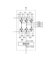
- FIG. FIG. 2 is a diagram showing a configuration example of an inverter included in the power converter according to Embodiment 1;
- FIG. 4 is a diagram showing an example of waveforms of load current and phase currents output from the inverter when current peak control is performed by the control device for the power conversion device according to Embodiment 1;
- FIG. 4 is a diagram showing examples of waveforms of load current and phase currents output from the inverter when load current control is performed by the control device for the power conversion device according to Embodiment 1;
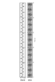
- FIG. 4 is a diagram showing the strength of the current flowing through the motor at each frequency when the control device for the power conversion device according to the first embodiment performs load current control;
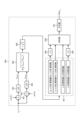
- FIG. 2 is a block diagram showing a configuration example of a control device included in the power conversion device according to Embodiment 1;
- FIG. 3 is a block diagram showing a configuration example of a voltage command value calculation unit included in the control device according to Embodiment 1;
- 4 is a block diagram showing a configuration example of a power supply harmonic standard value calculation unit provided in the voltage command value calculation unit according to the first embodiment;
- FIG. FIG. 3 is a block diagram showing a configuration example of an order component calculation section included in the voltage command value calculation section according to the first embodiment;
- a power conversion device, a motor drive device, and a refrigeration cycle application device will be described below in detail based on the drawings.
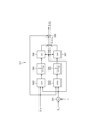
- FIG. 1 is a diagram showing a configuration example of a power converter 200 according to Embodiment 1.
- FIG. 2 is a diagram showing a configuration example of the inverter 30 included in the power conversion device 200 according to Embodiment 1.
- Power converter 200 is connected to commercial power source 1 and compressor 8 .
- the power conversion device 200 converts the first AC power of the power supply voltage Vs supplied from the commercial power supply 1 into the second AC power having desired amplitude and phase, and supplies the second AC power to the compressor 8 .
- Power converter 200 includes reactor 2 , rectifier 3 , smoothing capacitor 5 , inverter 30 , bus voltage detector 10 , load current detector 40 , and controller 100 .
- a motor drive device 400 is configured by the power conversion device 200 and the motor 7 included in the compressor 8 .
- the commercial power supply 1 is assumed to have a frequency of 50 Hz or 60 Hz, but is not limited to these. Moreover, the commercial power source 1 may be a distributed power source as long as it can output AC power.
- Reactor 2 is connected between commercial power source 1 and rectifying section 3 .
- the reactor 2 has a shape such as an EI shape, an EE shape, or the like, in which electromagnetic steel plates or the like are laminated, uses an iron core such as ferrite or amorphous, and has a winding made of copper, aluminum, or the like.
- the rectifying section 3 has a bridge circuit composed of rectifying elements 131 to 134, rectifies the first AC power of the power supply voltage Vs supplied from the commercial power supply 1, and outputs it.
- the rectifier 3 performs full-wave rectification.
- the rectifying elements 131 to 134 are, for example, diodes, but may be power semiconductors such as MOSFETs (Metal-Oxide-Semiconductor Field-Effect Transistors).
- the smoothing capacitor 5 is a smoothing element that is connected to the output terminal of the rectifier 3 and smoothes the power rectified by the rectifier 3 .
- the smoothing capacitor 5 is, for example, a capacitor such as an electrolytic capacitor or a film capacitor.
- the smoothing capacitor 5 has a capacity for smoothing the power rectified by the rectifier 3, and the voltage generated in the smoothing capacitor 5 by the smoothing has a DC component rather than a full-wave rectified waveform of the commercial power supply 1. It has a waveform shape in which a voltage ripple corresponding to the frequency of the commercial power supply 1 is superimposed, and does not pulsate greatly.
- the frequency of this voltage ripple is a two-fold component of the frequency of the power supply voltage Vs when the commercial power supply 1 is single-phase, and a six-fold component is the main component when the commercial power supply 1 is three-phase. If the power input from commercial power supply 1 and the power output from inverter 30 do not change, the amplitude of this voltage ripple is determined by the capacity of smoothing capacitor 5 . For example, it pulsates in such a range that the maximum value of the voltage ripple generated in the smoothing capacitor 5 is less than twice the minimum value.
- the bus voltage detection unit 10 is a detection unit that detects the voltage across the smoothing capacitor 5 , that is, the voltage across the DC buses 12 a and 12 b as a bus voltage Vdc , and outputs the detected voltage value to the control device 100 .
- Load current detection unit 40 is a detection unit that detects load current Idc , which is a direct current flowing into inverter 30 from smoothing capacitor 5 , and outputs the detected current value to control device 100 .
- the inverter 30 is connected across the smoothing capacitor 5 and converts the power output from the rectifier 3 and the smoothing capacitor 5 into second AC power having a desired amplitude and phase, that is, generates the second AC power. and output to the motor 7. Specifically, inverter 30 receives bus voltage Vdc , generates a three-phase AC voltage with variable frequency and voltage value, and supplies it to motor 7 via output lines 331-333.
- the inverter 30 includes an inverter main circuit 310 and a drive circuit 350, as shown in FIG. Input terminals of the inverter main circuit 310 are connected to the DC buses 12a and 12b.
- the inverter main circuit 310 includes switching elements 311-316. Freewheeling rectifying elements 321 to 326 are connected in anti-parallel to the switching elements 311 to 316, respectively.
- the drive circuit 350 generates drive signals Sr1-Sr6 based on PWM (Pulse Width Modulation) signals Sm1-Sm6 output from the control device 100.
- PWM Pulse Width Modulation
- the drive circuit 350 controls on/off of the switching elements 311-316 by the drive signals Sr1-Sr6.
- the inverter 30 can supply the three-phase AC voltage with variable frequency and variable voltage to the motor 7 via the output lines 331-333.
- the PWM signals Sm1 to Sm6 are signals having a logic circuit signal level, that is, a magnitude of 0V to 5V.
- the PWM signals Sm1 to Sm6 are signals having the ground potential of the control device 100 as a reference potential.
- the driving signals Sr1 to Sr6 are signals having voltage levels necessary to control the switching elements 311 to 316, eg, -15V to +15V.
- the drive signals Sr1 to Sr6 are signals having the potential of the negative terminal, that is, the emitter terminal of the corresponding switching elements 311 to 316 as a reference potential.
- the compressor 8 is a load having a motor 7 for driving compression.
- the motor 7 rotates according to the amplitude and phase of the second AC power supplied from the inverter 30 and performs compression operation.
- the load torque of the compressor 8 can often be regarded as a constant torque load.
- FIG. 1 shows a case where the motor windings are Y-connected, but this is an example and is not limited to this.
- the motor windings of the motor 7 may be delta-connection, or may be switchable between Y-connection and delta-connection.
- the compressor 8 is assumed to be a single rotary compressor, a scroll compressor, or the like, but is not limited to these.
- the arrangement of each configuration shown in FIG. 1 is an example, and the arrangement of each configuration is not limited to the example shown in FIG.
- the reactor 2 may be arranged after the rectifying section 3 .
- the power conversion device 200 may include a booster section, or the rectifier section 3 may have the function of the booster section.
- the bus voltage detection section 10 and the load current detection section 40 may be collectively referred to as a detection section.
- the voltage value detected by the bus voltage detection unit 10 and the current value detected by the load current detection unit 40 may be referred to as detection values.
- Control device 100 acquires bus voltage Vdc from bus voltage detector 10 and load current Idc from load current detector 40 .
- Control device 100 controls the operation of inverter main circuit 310, specifically, the on/off of switching elements 311 to 316 included in inverter main circuit 310, using the detection values detected by the respective detection units.
- control device 100 controls the operation of inverter 30 so as to suppress the generation of power source harmonics generated in power conversion device 200 . It should be noted that the control device 100 does not have to use all the detection values acquired from each detection unit, and may perform control using some of the detection values.
- control device 100 the load connected across the smoothing capacitor 5 is, for example, a load composed of an inverter 30 and a motor 7 as shown in FIG. It is not limited to these as long as it is a load that occurs.
- FIG. 3 is a diagram showing an example of waveforms of load current Idc and phase currents output from inverter 30 when current peak control is performed by control device 100 of power conversion device 200 according to the first embodiment. be.
- the upper stage shows the waveform of the load current Idc
- the lower stage shows the waveform of the phase current. Note that each horizontal axis indicates time.
- the phase currents are currents flowing through output lines 331 to 333 between inverter 30 and motor 7 .
- the peaks of the phase currents flowing through the output lines 331 to 333, ie, the three phases are all aligned. Note that, as a feature at this time, as shown in the upper part of FIG.
- FIG. 4 is a diagram showing an example of the waveform of the load current Idc and the waveform of the phase current output from the inverter 30 when the load current is controlled by the control device 100 of the power conversion device 200 according to the first embodiment. be.
- the upper stage shows the waveform of the load current Idc
- the lower stage shows the waveform of the phase current. Note that each horizontal axis indicates time.
- Load current control is control for suppressing power supply harmonics in control device 100 .
- the principle behind the increase in power supply harmonics is that the load current Idc , which is the charging/discharging current of the smoothing capacitor 5, becomes unbalanced between the positive and negative sides .
- the peak value changes with time as compared to the current peak control shown in the lower part of FIG. 4.
- the current peak control is realized, for example, by providing a filter for the output of the frequency estimator and controlling so that the ⁇ -axis current command value, which is the torque current, does not fluctuate.
- load current control is controlled without using the filter. Therefore, by gradually changing the cutoff frequency of the filter and gradually weakening the attenuation effect of the filter, it is possible to change from current peak control to load current control. As a result, fluctuations in the torque current are allowed, and the peak current can be fluctuated in accordance with the machine 1f component. Details will be described later.
- the load mechanically changes in one rotation, that is, changes in mechanical 1f.
- the motor 7 is controlled to keep the current peak constant by outputting a constant torque from the inverter 30 . Therefore, the motor 7 operates so that the speed decreases when the load is high and the speed increases when the load is low. Therefore, as shown in the lower part of FIG. 3, the current flowing through the motor 7, that is, the current peak of the phase current becomes a waveform in which the frequency fluctuates with the mechanical 1f cycle.
- phase current is frequency-modulated
- the mechanical 1f component is fm and the number of poles of the motor 7 is Pm
- the electrical 1f component of the motor 7 is Pm ⁇ fm
- the load current Idc is controlled to approach a desired value. That is, the load current control operates to reduce the current when the load is high and to increase the current when the load is low. Therefore, the current flowing through the motor 7 has a waveform in which the peak of the current increases and decreases in the machine 1f cycle. That is, the phase current is in an amplitude-modulated state.
- the modulated wave which is the waveform after amplitude modulation, is given by equation (2).
- A indicates the amplitude
- m indicates the modulation index
- ⁇ s indicates the angular frequency of the modulating wave
- ⁇ s indicates the phase of the modulating wave
- ⁇ c indicates the angular frequency of the carrier wave
- ⁇ c It shows the phase of the carrier wave.
- FIG. 5 is a diagram showing an example of a frequency spectrum of a modulated wave in general amplitude modulation.
- the horizontal axis indicates frequency
- the vertical axis indicates intensity at each frequency.
- fs indicates the frequency of the modulating wave
- fc indicates the frequency of the carrier wave. It should be noted here that the frequency fs of the modulated wave becomes prominent before and after the amplitude modulation.
- FIG. 6 shows waveforms of frequency analysis results during actual load current control.
- FIG. 6 is a diagram showing the intensity of the current flowing through the motor 7 at each frequency when the control device 100 of the power conversion device 200 according to Embodiment 1 performs load current control.
- the horizontal axis indicates frequency
- the vertical axis indicates current intensity.
- the control device 100 performs current peak control to reduce fluctuations in the amplitude of the current supplied to the motor 7, and controls the load current Idc , which is the output current of the smoothing capacitor 5, to approach a desired value. Performs load current control.
- the control device 100 changes the current output by the inverter 30 so as to increase or decrease the mechanical 1f component of the current flowing through the motor 7, so that each control can be switched smoothly. It becomes possible.
- FIG. 7 is a block diagram showing a configuration example of the control device 100 included in the power conversion device 200 according to Embodiment 1. As shown in FIG.
- the control device 100 includes an operation control section 102 and an inverter control section 110 .
- the operation control unit 102 receives command information Q e from the outside and generates a frequency command value ⁇ e * based on the command information Q e .
- the frequency command value ⁇ e * is obtained by multiplying the rotation angular velocity command value ⁇ m * , which is the command value of the rotation speed of the motor 7, by the number of pole pairs P m of the motor 7, as shown in the following equation (4). be able to.
- the control device 100 controls the operation of each part of the air conditioner based on the command information Qe .
- the command information Qe includes, for example, a temperature detected by a temperature sensor (not shown), information indicating a set temperature instructed by a remote controller (not shown), operation mode selection information, operation start and operation end instruction information, and the like. is.
- the operation modes are, for example, heating, cooling, and dehumidification.
- the operation control unit 102 may be outside the control device 100 . That is, control device 100 may be configured to acquire frequency command value ⁇ e * from the outside.
- the inverter control unit 110 includes a current restoration unit 111, a three-phase to two-phase conversion unit 112, an excitation current command value generation unit 113, a voltage command value calculation unit 115, an electric phase calculation unit 116, and a two-to-three phase conversion unit.
- a section 117 and a PWM signal generation section 118 are provided.
- a current restoration unit 111 restores the phase currents i u , iv , and i w flowing through the motor 7 based on the load current I dc detected by the load current detection unit 40 .
- Current restoration unit 111 samples load current Idc detected by load current detection unit 40 at timing determined based on PWM signals Sm1 to Sm6 generated by PWM signal generation unit 118, thereby obtaining phase current i u , i v , i w can be recovered.
- the three-phase to two-phase conversion unit 112 converts the phase currents i u , iv , and i w restored by the current restoration unit 111 to the ⁇ -axis using the electric phase ⁇ e generated by the electric phase calculation unit 116 described later.
- An excitation current i ⁇ that is a current and a torque current i ⁇ that is a ⁇ -axis current, that is, are converted into current values of the ⁇ -axis.
- the excitation current command value generator 113 generates the excitation current command value i ⁇ * in the above-described rotating coordinate system. Specifically, the excitation current command value generation unit 113 obtains the optimum excitation current command value i ⁇ * for driving the motor 7 with the highest efficiency based on the torque current i ⁇ . Based on the torque current i ⁇ , the excitation current command value generator 113 generates a current phase at which the output torque Tm of the motor 7 becomes a specified value or more or a maximum value, that is, the current value becomes a specified value or less or a minimum value. An exciting current command value i ⁇ * that becomes ⁇ m is output.
- the excitation current command value generator 113 obtains the excitation current command value i ⁇ * based on the torque current i ⁇ , but this is an example and the present invention is not limited to this. Even if the excitation current command value generator 113 obtains the excitation current command value i ⁇ * based on the excitation current i ⁇ , the frequency command value ⁇ e * , etc., the same effect can be obtained. Further, the excitation current command value generator 113 may determine the excitation current command value i ⁇ * by flux weakening control or the like. In the following description, the exciting current command value may be referred to as the ⁇ -axis current command value.
- the voltage command value calculation unit 115 calculates the load current I dc obtained from the load current detection unit 40, the frequency command value ⁇ e * obtained from the operation control unit 102, and the excitation current i ⁇ -axis voltage command value V ⁇ * and ⁇ -axis voltage command value V ⁇ * are generated based on ⁇ and torque current i ⁇ and excitation current command value i ⁇ * obtained from excitation current command value generation unit 113 . Furthermore, the voltage command value calculation unit 115 calculates the frequency estimated value ⁇ est based on the ⁇ -axis voltage command value V ⁇ * , the ⁇ -axis voltage command value V ⁇ * , the excitation current i ⁇ , and the torque current i ⁇ . to estimate
- the electric phase calculation unit 116 calculates the electric phase ⁇ e by integrating the frequency estimation value ⁇ est acquired from the voltage command value calculation unit 115 .
- Two-to-three phase converter 117 converts ⁇ -axis voltage command value V ⁇ * and ⁇ -axis voltage command value V ⁇ * obtained from voltage command value calculator 115, that is, voltage command values in a two-phase coordinate system, to electrical phase calculation.
- the electric phase ⁇ e acquired from the unit 116 the three-phase voltage command values V u * , V v * , V w * , which are the output voltage command values in the three-phase coordinate system, are converted.
- PWM signal generation unit 118 converts three-phase voltage command values V u * , V v * , V w * obtained from two-to-three phase conversion unit 117 and bus voltage V dc detected by bus voltage detection unit 10. The comparison generates PWM signals Sm1-Sm6. The PWM signal generator 118 can also stop the motor 7 by not outputting the PWM signals Sm1 to Sm6.
- control device 100 performs control in a rotating coordinate system having ⁇ and ⁇ axes.
- ⁇ -axis current, ⁇ -axis current, etc. may be referred to as excitation current, torque current, and the like.
- FIG. 8 is a block diagram showing a configuration example of voltage command value calculation section 115 included in control device 100 according to the first embodiment.
- Voltage command value calculation section 115 includes frequency estimation section 501, adjustment section 502, integral control section 508, mechanical angle phase calculation section 509, subtraction section 510, current peak control section 511, and speed control section 512. , a load current controller 513 , an adder 514 , subtractors 515 and 516 , a ⁇ -axis current controller 517 , and a ⁇ -axis current controller 518 .
- the adjustment unit 502 includes a power harmonic standard value calculation unit 503 , an order component calculation unit 504 , a subtraction unit 505 , an integration control unit 506 and a setting unit 507 .
- the frequency estimator 501 calculates the frequency of the voltage supplied to the motor 7 based on the excitation current i ⁇ , the torque current i ⁇ , the ⁇ -axis voltage command value V ⁇ * , and the ⁇ -axis voltage command value V ⁇ *. is estimated and output as the frequency estimate ⁇ est .
- the adjustment unit 502 adjusts the control ratios of the current peak control performed by the current peak control unit 511 and the load current control performed by the load current control unit 513 in the control device 100 .
- power harmonic standard value calculating section 503 calculates a power harmonic standard value for each order of power harmonics.
- FIG. 9 is a block diagram showing a configuration example of power supply harmonic standard value calculation section 503 included in voltage command value calculation section 115 according to the first embodiment.
- the power harmonic standard value calculator 503 includes a power calculator 611 , a power multiplier 612 , a limit value converter 613 , and a coefficient multiplier 614 .
- Power calculation unit 611 uses ⁇ -axis voltage command value V ⁇ * , ⁇ -axis voltage command value V ⁇ * , excitation current i ⁇ , and torque current i ⁇ to calculate ⁇ -axis voltage command value V ⁇ * ⁇ excitation current i
- the electric power W is calculated by the formula of ⁇ + ⁇ -axis voltage command value V ⁇ * ⁇ torque current i ⁇ .
- the power multiplier 612 calculates the power exceeding the specified 600 watts from the power W as (W-600), and multiplies the calculated value by the second term of the maximum allowable harmonic current specified for each order. . 600 watts is a value specified in JIS (Japanese Industrial Standards) C 61000-3-2. In the example of FIG. 8, "1.08+0.00033" is the maximum allowable harmonic current when the order of power supply harmonics is 2, so the power multiplier 612 outputs "1.08+0.00033 (W-600)". Calculate as The power multiplier 612 performs similar calculations for other orders of power supply harmonics.
- the limit value conversion unit 613 multiplies the value of each order obtained by the power multiplication unit 612 by (230/power supply voltage) to calculate the limit value for each order.
- 230 is the value when the power supply is single-phase, as specified in the aforementioned JIS C 61000-3-2.
- the power supply voltage is 100V or 200V in a general usage environment.
- a coefficient multiplier 614 multiplies a coefficient K of 0 ⁇ K ⁇ 1 to set a margin for the limit value for each order obtained by the limit value conversion unit 613, and obtains a power supply harmonic for each order in power supply harmonics.
- the order component calculation unit 504 calculates each order component of the power supply harmonic using the load current Idc .
- FIG. 10 is a block diagram showing a configuration example of order component calculation section 504 included in voltage command value calculation section 115 according to the first embodiment.
- the order component calculation unit 504 includes multiplication units 621 and 622, low-pass filters 623 and 624, a peak value calculation unit 625, an effective value calculation unit 626, a squaring unit 627, division units 628 and 629, and an addition unit. 630 and a 1/2 power part 631 .
- the order component calculation unit 504 does not target only integer values, but targets the entire range by cooperating with orders before and after.
- the order component calculation unit 504 targets the 1.5th to 2.5th orders when targeting the second order, and targets the 2.5th to 3.5th orders when targeting the third order. .
- the order component calculation unit 504 performs calculation in units of 5 Hz in the range from 75 Hz to 125 Hz when the order is secondary. Therefore, order component calculation section 504 performs multiplication sections 621 and 622, low-pass filters 623 and 624, peak value calculation section 625, and effective value calculation section 626 for the target order times the frequency components to be calculated for each order. Be prepared for a few minutes.
- the multiplier 621 multiplies the load current Idc by the cosine cos ⁇ x of the frequency component ⁇ x to be calculated.
- the multiplier 622 multiplies the load current I dc by the sine sin ⁇ x of the frequency component ⁇ x to be calculated.
- a low-pass filter 623 removes the AC component from the calculated value obtained by the multiplier 621 and extracts the DC component.
- a low-pass filter 624 removes the AC component from the calculated value obtained by the multiplier 622 and extracts the DC component.
- the peak value calculator 625 uses Idccosx obtained from the lowpass filter 623 and Idcsinx obtained from the lowpass filter 624 to calculate the peak value of the frequency component ⁇ x to be calculated.
- the effective value calculator 626 divides the peak value of the frequency component ⁇ x to be calculated obtained by the peak value calculator 625 by ⁇ (2) to obtain the effective value of the frequency component ⁇ x to be calculated. Calculate. ⁇ (2) represents the square root of two.
- the squaring unit 627 squares the effective value calculated at each frequency of the order to be calculated.
- the minimum frequency among the frequency components is (n-1).
- the maximum frequency is n. It is described as fifth order. For example, when the order is 2, the minimum frequency is 1.5 and the maximum frequency is 2.5.
- the minimum frequency is the same as the maximum frequency of the next lower order, and the maximum frequency is the same as the minimum frequency of the one higher order.
- a division unit 628 halves the square value of the effective value of the minimum frequency obtained by the squaring unit 627 in order to eliminate the influence of overlapping portions.
- a division unit 629 halves the square value of the effective value of the maximum frequency obtained by the squaring unit 627 in order to eliminate the influence of overlapping portions.
- Adder 630 obtains a total value by adding the values obtained by squaring the effective values calculated at each frequency of the order to be calculated, or the values obtained by halving the squared values.
- a 1/2 power unit 631 takes the square root of the total value obtained by the addition unit 630 to obtain the magnitude of the order component to be calculated.
- the order component calculation unit 504 performs similar calculations for each order.
- the subtraction unit 505 calculates the power harmonic standard value tolerance. Specifically, the subtraction unit 505 subtracts the power harmonic standard value calculated by the power harmonic standard value calculation unit 503 and the power harmonic order component calculated by the order component calculation unit 504 for each order. Compute the difference. The subtraction unit 505 outputs the calculated difference to the integration control unit 506 as the power supply harmonic standard value tolerance.
- the integral control unit 506 performs integral control on the power supply harmonic standard value tolerance calculated by the subtraction unit 505 to bring the difference closer to 0, that is, the order component of the power supply harmonic calculated by the order component calculation unit 504. to the power harmonic standard value calculated by the power harmonic standard value calculation unit 503, the current value idck is calculated.
- Setting unit 507 sets cutoff frequency ⁇ ff for current peak control unit 511 and cutoff frequency ⁇ fs for load current control unit 513 based on current value i dck calculated by integral control unit 506 .
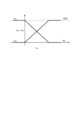
- FIG. 11 is a diagram showing an example of the content of control by setting unit 507 included in voltage command value calculation unit 115 according to the first embodiment.
- the reciprocal of the time constant is the cutoff frequency
- the setting unit 507 makes the cutoff frequencies ⁇ ff and ⁇ fs variable according to the current value i dck .
- the setting unit 507 increases the cutoff frequency ⁇ ff and decreases the cutoff frequency ⁇ fs in the range where the current value i dck is 0 or more, that is, in the range where there is a margin for the harmonic standard.
- the adjustment unit 502 preferentially operates the current peak control unit 511 to suppress the operation of the load current control unit 513 in an operating range that has a margin for the harmonic standard.
- the control amount of the load current control section 513 can be decreased by increasing the control amount.
- the setting unit 507 decreases the cutoff frequency ⁇ ff and increases the cutoff frequency ⁇ fs in the range where the current value i dck is less than 0, that is, in the range where there is no margin for the harmonic standard.
- the adjustment unit 502 suppresses the operation of the current peak control unit 511 and preferentially operates the load current control unit 513 in the operating range where there is no margin for the harmonic standard.
- the control amount of the load current control section 513 can be increased by decreasing the control amount.
- the setting unit 507 gradually changes each cutoff frequency within a specified range in which the current value idck is 0 or more, thereby preventing a situation in which switching shock of each control is caused. It is possible to avoid.
- the setting unit 507 linearly changes the value of each cutoff frequency in the example of FIG. 11, but this is an example and is not limited to this. Since the setting unit 507 only needs to be able to continuously change the value of each cutoff frequency, it may change the value of each cutoff frequency using a function other than a linear function.
- the setting unit 507 may calculate the value of each cutoff frequency according to the current value idck using a function as described above, or may calculate the value of each cutoff frequency according to the current value idck . It may be stored in advance and the value of each cutoff frequency may be read from the value of the current value idck .
- Integral control section 508 performs integral control on frequency estimation value ⁇ est acquired from frequency estimating section 501 .
- the mechanical angle phase calculation unit 509 multiplies the value obtained by the integral control unit 508 by 1/ Pm , that is, divides the value obtained by the integral control unit 508 by the pole log number Pm of the motor 7. Calculate the mechanical angle phase ⁇ m .
- Subtraction unit 510 calculates the difference ( ⁇ e * ⁇ est ) between frequency command value ⁇ e * and frequency estimated value ⁇ est estimated by frequency estimation unit 501 as speed deviation ⁇ .
- a current peak control unit 511 performs current peak control to keep the ⁇ -axis current constant. Specifically, current peak control section 511 removes the load fluctuation component included in speed deviation ⁇ based on mechanical angle phase ⁇ m . The current peak control unit 511 outputs the speed deviation ⁇ from which the load fluctuation component is removed to the speed control unit 512 as a new speed deviation ⁇ f .
- the current peak controller 511 is configured by, for example, a notch filter.
- FIG. 12 is a block diagram showing a configuration example of current peak control section 511 included in voltage command value calculation section 115 according to the first embodiment.
- Current peak control section 511 includes multiplication section 541, sine calculation section 542, cosine calculation section 543, low-pass filters 544 and 545, sine calculation section 546, cosine calculation section 547, addition section 548, and subtraction section. 549, and
- the multiplier 541 multiplies the mechanical angle phase ⁇ m by n to calculate the frequency component n ⁇ ⁇ m to be controlled.
- the sine calculator 542 multiplies the speed deviation ⁇ by the sine sin(n ⁇ m ) of the frequency component n ⁇ m to be controlled.
- a low-pass filter 544 performs low-pass filtering with a time constant Tff , removes AC components from the calculated value obtained by the sine calculator 542, and extracts DC components.
- s is the Laplacian operator.
- a sine calculator 546 multiplies the DC component extracted by the low-pass filter 544 by a sine sin (n ⁇ m ) to calculate a DC component in the imaginary axis direction on the complex plane.
- the cosine calculator 543 multiplies the speed deviation ⁇ by the cosine cos (n ⁇ m ) of the frequency component n ⁇ m to be controlled.
- a low-pass filter 545 performs low-pass filtering with a time constant Tff , removes AC components from the calculated values obtained by the cosine calculator 543, and extracts DC components.
- a cosine calculator 547 multiplies the DC component extracted by the low-pass filter 545 by cosine cos (n ⁇ m ) to calculate a DC component in the real axis direction on the complex plane.
- the addition unit 548 adds the DC component in the imaginary axis direction on the complex plane calculated by the sine calculation unit 546 and the DC component in the real axis direction on the complex plane calculated by the cosine calculation unit 547, and obtains the mechanical angle Generate an alternating quantity ⁇ nf due to the n-fold frequency component.
- a subtraction unit 549 calculates the difference between the speed deviation ⁇ and the AC amount ⁇ nf .
- the subtraction unit 549 outputs the difference between the speed deviation ⁇ and the alternating current amount ⁇ nf as the speed deviation ⁇ f obtained by removing the alternating current amount ⁇ nf caused by the n-fold component of the mechanical angular frequency from the speed deviation ⁇ .
- a speed control unit 512 calculates a first torque current command value i ⁇ * , which is a ⁇ -axis current command value, based on the speed deviation ⁇ f calculated by the current peak control unit 511 .
- the speed control unit 512 performs, for example, proportional control, integral control, or the like to calculate the first torque current command value i ⁇ * .
- a load current control unit 513 performs load current control to keep the load current Idc at a constant value. Specifically, the load current control unit 513 removes the load fluctuation component included in the load current Idc flowing into the load based on the mechanical angle phase ⁇ m . Load current control section 513 outputs the result obtained by removing the load fluctuation component from load current I dc to adding section 514 as AC quantity i ⁇ lcc * .
- the load current control unit 513 is configured by, for example, a notch filter.
- FIG. 13 is a block diagram showing a configuration example of load current control section 513 included in voltage command value calculation section 115 according to the first embodiment.
- Load current control section 513 includes multiplication section 521, sine calculation section 522, cosine calculation section 523, low-pass filters 524 and 525, subtraction sections 526 and 527, integration control sections 528 and 529, and sine calculation section 530. , a cosine calculator 531 , and an adder 532 .
- the multiplier 521 multiplies the mechanical angle phase ⁇ m by n to calculate the frequency component n ⁇ ⁇ m to be controlled.
- the sine calculator 522 multiplies the load current I dc by the sine sin(n ⁇ m ) of the frequency component n ⁇ m to be controlled.
- the low-pass filter 524 performs low-pass filtering with a time constant Tfs , removes the AC component from the calculated value obtained by the sine calculator 522, and extracts the DC component.
- the subtraction unit 526 calculates the difference between the DC component and 0 so that the DC component obtained by the low-pass filter 524 becomes 0.
- the integral control unit 528 performs integral control on the difference obtained by the subtraction unit 526 to calculate the sine component of the current command value that brings the difference closer to zero.
- Sine calculator 530 multiplies the sine component of the current command value calculated by integral controller 528 by sine sin (n ⁇ m ) to calculate an AC component in the imaginary axis direction on the complex plane.
- the cosine calculator 523 multiplies the load current I dc by the cosine cos (n ⁇ m ) of the frequency component n ⁇ m to be controlled.
- the low-pass filter 525 performs low-pass filtering with a time constant Tfs , removes AC components from the calculated values obtained by the cosine calculator 523, and extracts DC components.
- the subtraction unit 527 calculates the difference between the DC component and 0 so that the DC component obtained by the low-pass filter 525 becomes 0.
- the integral control unit 529 performs integral control on the difference obtained by the subtraction unit 527 to calculate the cosine component of the current command value that brings the difference closer to zero.
- Cosine calculator 531 multiplies the cosine component of the current command value calculated by integral controller 529 by cosine cos (n ⁇ m ) to calculate the AC component in the real axis direction on the complex plane.
- the addition unit 532 adds the AC component in the imaginary axis direction on the complex plane calculated by the sine calculation unit 530 and the AC component in the real axis direction on the complex plane calculated by the cosine calculation unit 531, and obtains the mechanical angle Generate an alternating quantity i ⁇ lcc * due to the n-fold frequency component.
- the control device 100 controls the power conversion device 200 so that the 1f component of the mechanical frequency of the current supplied to the motor 7 becomes significant at motor operating frequencies that are 0.6 times and 1.4 times the power frequency of the commercial power source 1.
- Control device 100 may grasp the power supply frequency of commercial power supply 1 from the value of load current Idc obtained from load current detection unit 40 and the content of control for inverter 30, or may determine the power supply frequency of commercial power supply 1 to which commercial power supply 1 is connected. In this case, information on the power supply frequency of the commercial power supply 1 may be held in advance. Further, the control device 100 can grasp the mechanical frequency, which is the operating frequency of the motor 7 , from the details of control over the inverter 30 .
- Addition unit 514 adds first torque current command value i ⁇ * generated by speed control unit 512 and AC quantity i ⁇ lcc * generated by load current control unit 513 to obtain a ⁇ -axis current command value A second torque current command value i ⁇ ** is generated.
- the subtraction unit 515 calculates the difference (i ⁇ * ⁇ i ⁇ ) of the excitation current i ⁇ with respect to the excitation current command value i ⁇ * .
- Subtraction unit 516 calculates the difference (i ⁇ ** - i ⁇ ) of torque current i ⁇ with respect to second torque current command value i ⁇ ** .
- the ⁇ -axis current control unit 517 performs a proportional integral operation on the difference (i ⁇ * ⁇ i ⁇ ) calculated by the subtraction unit 515 to bring the difference (i ⁇ * ⁇ i ⁇ ) close to zero.
- a command value V ⁇ * is generated.
- the ⁇ -axis current control unit 517 generates the ⁇ -axis voltage command value V ⁇ * in this manner, thereby performing control to match the excitation current i ⁇ with the excitation current command value i ⁇ * .
- a ⁇ -axis current control unit 518 performs a proportional integral operation on the difference (i ⁇ ** - i ⁇ ) calculated by the subtraction unit 516 to bring the difference (i ⁇ ** - i ⁇ ) closer to zero ⁇
- a shaft voltage command value V ⁇ * is generated.
- the ⁇ -axis current control unit 518 generates the ⁇ -axis voltage command value V ⁇ * in this manner, thereby performing control to match the torque current i ⁇ with the second torque current command value i ⁇ ** . .
- the control device 100 adjusts the control ratios of the current peak control and the load current control.
- the operation of the inverter 30 is controlled so that the 1-fold component becomes large.
- the control device 100 controls the current supplied to the motor 7 to increase the mechanical frequency, which is the operating frequency of the motor 7. is greater than when load current control is not performed.
- FIG. 14 is a flow chart showing the operation of the control device 100 included in the power converter 200 according to the first embodiment.
- the adjustment unit 502 adjusts the control ratios of the current peak control performed by the current peak control unit 511 and the load current control performed by the load current control unit 513, A cutoff frequency ⁇ ff and a cutoff frequency ⁇ fs for the load current control unit 513 are set (step S1).
- the current peak control unit 511 performs current peak control using the cutoff frequency ⁇ ff to generate a speed deviation ⁇ f (step S2).
- the speed control unit 512 uses the speed deviation ⁇ f to generate the first torque current command value i ⁇ * (step S3).
- the load current control unit 513 performs load current control using the cutoff frequency ⁇ fs to generate the alternating current amount i ⁇ lcc * (step S4).
- the adder 514 adds the first torque current command value i ⁇ * and the AC quantity i ⁇ lcc * to generate the second torque current command value i ⁇ ** (step S5).
- FIG. 15 is a diagram showing an example of a hardware configuration that implements the control device 100 included in the power conversion device 200 according to Embodiment 1. As shown in FIG. Control device 100 is implemented by processor 91 and memory 92 .
- the processor 91 is a CPU (Central Processing Unit, central processing unit, processing unit, arithmetic unit, microprocessor, microcomputer, processor, DSP (Digital Signal Processor)), or a system LSI (Large Scale Integration).
- the memory 92 is a RAM (Random Access Memory), a ROM (Read Only Memory), a flash memory, an EPROM (Erasable Programmable Read Only Memory), an EEPROM (registered trademark) (Electrically Erasable Programmable Read Only Memory) or a volatile non-volatile Read Only memory.
- a semiconductor memory can be exemplified.
- the memory 92 is not limited to these, and may be a magnetic disk, an optical disk, a compact disk, a mini disk, or a DVD (Digital Versatile Disc).
- control device 100 performs current peak control for reducing power consumption and load current Idc , which is the output current of smoothing capacitor 5, to a desired value. Load current control is performed so that it approaches the value. Control device 100 adjusts the control ratios of current peak control and load current control according to the operating state of inverter 30 that outputs the second AC power to motor 7 , that is, the control content for inverter 30 . Thereby, the power conversion device 200 can adjust the control amount of the control for reducing the power consumption and the control for suppressing the generation of harmonic components.
- the control device 100 uses the ⁇ -axis current, which is a reactive current, instead of the ⁇ -axis current, which is an active current, and utilizes the change in active power due to the winding resistance of the motor 7 to convert the inverter
- the load current Idc which is the direct current flowing into the circuit 30
- a specified value that is, a constant value
- FIG. 16 is a diagram showing a configuration example of a refrigeration cycle device 900 according to Embodiment 2.
- a refrigerating cycle applied equipment 900 according to the second embodiment includes the power converter 200 described in the first embodiment.
- the refrigerating cycle applied equipment 900 according to Embodiment 2 can be applied to products equipped with a refrigerating cycle, such as air conditioners, refrigerators, freezers, and heat pump water heaters.
- constituent elements having functions similar to those of the first embodiment are denoted by the same reference numerals as those of the first embodiment.
- Refrigerating cycle applied equipment 900 includes compressor 8 incorporating motor 7 in Embodiment 1, four-way valve 902, indoor heat exchanger 906, expansion valve 908, and outdoor heat exchanger 910 with refrigerant pipe 912. attached through
- a compression mechanism 904 for compressing refrigerant and a motor 7 for operating the compression mechanism 904 are provided inside the compressor 8 .
- the refrigeration cycle applied equipment 900 can perform heating operation or cooling operation by switching operation of the four-way valve 902 .
- Compression mechanism 904 is driven by motor 7 whose speed is controlled.
- the refrigerant is pressurized by the compression mechanism 904 and sent out through the four-way valve 902, the indoor heat exchanger 906, the expansion valve 908, the outdoor heat exchanger 910, and the four-way valve 902. Return to compression mechanism 904 .
- the refrigerant is pressurized by the compression mechanism 904 and sent through the four-way valve 902, the outdoor heat exchanger 910, the expansion valve 908, the indoor heat exchanger 906, and the four-way valve 902. Return to compression mechanism 904 .
- the indoor heat exchanger 906 acts as a condenser to release heat, and the outdoor heat exchanger 910 acts as an evaporator to absorb heat.
- the outdoor heat exchanger 910 acts as a condenser to release heat, and the indoor heat exchanger 906 acts as an evaporator to absorb heat.
- the expansion valve 908 reduces the pressure of the refrigerant to expand it.
Landscapes
- Engineering & Computer Science (AREA)
- Power Engineering (AREA)
- Control Of Ac Motors In General (AREA)
- Inverter Devices (AREA)
Priority Applications (3)
| Application Number | Priority Date | Filing Date | Title |
|---|---|---|---|
| JP2023554219A JP7592188B2 (ja) | 2021-10-22 | 2021-10-22 | 電力変換装置、モータ駆動装置および冷凍サイクル適用機器 |
| PCT/JP2021/039143 WO2023067811A1 (ja) | 2021-10-22 | 2021-10-22 | 電力変換装置、モータ駆動装置および冷凍サイクル適用機器 |
| CN202180103341.XA CN118104122A (zh) | 2021-10-22 | 2021-10-22 | 电力转换装置、马达驱动装置以及制冷循环应用设备 |
Applications Claiming Priority (1)
| Application Number | Priority Date | Filing Date | Title |
|---|---|---|---|
| PCT/JP2021/039143 WO2023067811A1 (ja) | 2021-10-22 | 2021-10-22 | 電力変換装置、モータ駆動装置および冷凍サイクル適用機器 |
Publications (1)
| Publication Number | Publication Date |
|---|---|
| WO2023067811A1 true WO2023067811A1 (ja) | 2023-04-27 |
Family
ID=86058107
Family Applications (1)
| Application Number | Title | Priority Date | Filing Date |
|---|---|---|---|
| PCT/JP2021/039143 Ceased WO2023067811A1 (ja) | 2021-10-22 | 2021-10-22 | 電力変換装置、モータ駆動装置および冷凍サイクル適用機器 |
Country Status (3)
| Country | Link |
|---|---|
| JP (1) | JP7592188B2 (https=) |
| CN (1) | CN118104122A (https=) |
| WO (1) | WO2023067811A1 (https=) |
Cited By (1)
| Publication number | Priority date | Publication date | Assignee | Title |
|---|---|---|---|---|
| JP7825794B1 (ja) * | 2025-07-11 | 2026-03-06 | 三菱電機株式会社 | 電力変換装置、モータ駆動装置および冷凍サイクル適用機器 |
Citations (3)
| Publication number | Priority date | Publication date | Assignee | Title |
|---|---|---|---|---|
| JP2009232591A (ja) * | 2008-03-24 | 2009-10-08 | Mitsubishi Electric Corp | 電動機駆動装置および空気調和機 |
| JP2017112755A (ja) * | 2015-12-17 | 2017-06-22 | 本田技研工業株式会社 | 回転電機及び回転電機制御装置 |
| JP2020058184A (ja) * | 2018-10-03 | 2020-04-09 | ファナック株式会社 | 電力供給モード切替え機能を有するモータ駆動装置 |
-
2021
- 2021-10-22 CN CN202180103341.XA patent/CN118104122A/zh active Pending
- 2021-10-22 JP JP2023554219A patent/JP7592188B2/ja active Active
- 2021-10-22 WO PCT/JP2021/039143 patent/WO2023067811A1/ja not_active Ceased
Patent Citations (3)
| Publication number | Priority date | Publication date | Assignee | Title |
|---|---|---|---|---|
| JP2009232591A (ja) * | 2008-03-24 | 2009-10-08 | Mitsubishi Electric Corp | 電動機駆動装置および空気調和機 |
| JP2017112755A (ja) * | 2015-12-17 | 2017-06-22 | 本田技研工業株式会社 | 回転電機及び回転電機制御装置 |
| JP2020058184A (ja) * | 2018-10-03 | 2020-04-09 | ファナック株式会社 | 電力供給モード切替え機能を有するモータ駆動装置 |
Cited By (1)
| Publication number | Priority date | Publication date | Assignee | Title |
|---|---|---|---|---|
| JP7825794B1 (ja) * | 2025-07-11 | 2026-03-06 | 三菱電機株式会社 | 電力変換装置、モータ駆動装置および冷凍サイクル適用機器 |
Also Published As
| Publication number | Publication date |
|---|---|
| JPWO2023067811A1 (https=) | 2023-04-27 |
| JP7592188B2 (ja) | 2024-11-29 |
| CN118104122A (zh) | 2024-05-28 |
Similar Documents
| Publication | Publication Date | Title |
|---|---|---|
| US20240372498A1 (en) | Power converter, motor drive device, and refrigeration cycle application apparatus | |
| WO2023073880A1 (ja) | 電力変換装置、モータ駆動装置および冷凍サイクル適用機器 | |
| JP7566175B2 (ja) | 電力変換装置、電動機駆動装置及び冷凍サイクル適用機器 | |
| WO2023073870A1 (ja) | 電力変換装置、モータ駆動装置および冷凍サイクル適用機器 | |
| JP7536200B2 (ja) | 電力変換装置、モータ駆動装置および冷凍サイクル適用機器 | |
| WO2023067811A1 (ja) | 電力変換装置、モータ駆動装置および冷凍サイクル適用機器 | |
| JP7166468B2 (ja) | 電動機駆動装置および冷凍サイクル適用機器 | |
| WO2023100359A1 (ja) | 電力変換装置、モータ駆動装置および冷凍サイクル適用機器 | |
| US20240014759A1 (en) | Control device, power conversion apparatus, motor drive unit, and applied refrigeration cycle apparatus | |
| WO2023105570A1 (ja) | 電力変換装置、モータ駆動装置及び冷凍サイクル適用機器 | |
| JP7330401B2 (ja) | 電力変換装置、モータ駆動装置および冷凍サイクル適用機器 | |
| JP7566174B2 (ja) | 電力変換装置、電動機駆動装置及び冷凍サイクル適用機器 | |
| JP7570536B2 (ja) | 電力変換装置および空気調和機 | |
| WO2023067774A1 (ja) | 電力変換装置、モータ駆動装置および冷凍サイクル適用機器 | |
| JP7592187B2 (ja) | 電力変換装置、モータ駆動装置および冷凍サイクル適用機器 | |
| JP7819347B2 (ja) | 電力変換装置、モータ駆動装置および冷凍サイクル適用機器 | |
| WO2023162106A1 (ja) | モータ駆動装置及び冷凍サイクル装置 | |
| WO2023047486A1 (ja) | 電力変換装置、電動機駆動装置及び冷凍サイクル適用機器 | |
| JP7515739B2 (ja) | 電力変換装置、電動機駆動装置及び冷凍サイクル適用機器 | |
| JP7515740B2 (ja) | 電力変換装置、電動機駆動装置及び冷凍サイクル適用機器 | |
| JP7825794B1 (ja) | 電力変換装置、モータ駆動装置および冷凍サイクル適用機器 | |
| JP7834200B2 (ja) | 電力変換装置、モータ駆動装置及び冷凍サイクル適用機器 | |
| JP7325671B2 (ja) | 電力変換装置、モータ駆動装置および冷凍サイクル適用機器 | |
| WO2021002002A1 (ja) | 電動機駆動装置及び冷凍サイクル適用機器 | |
| US20250219553A1 (en) | Power converting apparatus, motor drive apparatus, and refrigeration-cycle application device |
Legal Events
| Date | Code | Title | Description |
|---|---|---|---|
| 121 | Ep: the epo has been informed by wipo that ep was designated in this application |
Ref document number: 21961459 Country of ref document: EP Kind code of ref document: A1 |
|
| WWE | Wipo information: entry into national phase |
Ref document number: 2023554219 Country of ref document: JP |
|
| WWE | Wipo information: entry into national phase |
Ref document number: 202180103341.X Country of ref document: CN |
|
| NENP | Non-entry into the national phase |
Ref country code: DE |
|
| 122 | Ep: pct application non-entry in european phase |
Ref document number: 21961459 Country of ref document: EP Kind code of ref document: A1 |