WO2023067804A1 - 屋外配電盤のための風圧式シャッター - Google Patents
屋外配電盤のための風圧式シャッター Download PDFInfo
- Publication number
- WO2023067804A1 WO2023067804A1 PCT/JP2021/039125 JP2021039125W WO2023067804A1 WO 2023067804 A1 WO2023067804 A1 WO 2023067804A1 JP 2021039125 W JP2021039125 W JP 2021039125W WO 2023067804 A1 WO2023067804 A1 WO 2023067804A1
- Authority
- WO
- WIPO (PCT)
- Prior art keywords
- door
- flow path
- wind pressure
- shutter
- downstream
- Prior art date
- Legal status (The legal status is an assumption and is not a legal conclusion. Google has not performed a legal analysis and makes no representation as to the accuracy of the status listed.)
- Ceased
Links
Images




Classifications
-
- H—ELECTRICITY
- H02—GENERATION; CONVERSION OR DISTRIBUTION OF ELECTRIC POWER
- H02B—BOARDS, SUBSTATIONS OR SWITCHING ARRANGEMENTS FOR THE SUPPLY OR DISTRIBUTION OF ELECTRIC POWER
- H02B1/00—Frameworks, boards, panels, desks, casings; Details of substations or switching arrangements
- H02B1/56—Cooling; Ventilation
-
- F—MECHANICAL ENGINEERING; LIGHTING; HEATING; WEAPONS; BLASTING
- F24—HEATING; RANGES; VENTILATING
- F24F—AIR-CONDITIONING; AIR-HUMIDIFICATION; VENTILATION; USE OF AIR CURRENTS FOR SCREENING
- F24F13/00—Details common to, or for air-conditioning, air-humidification, ventilation or use of air currents for screening
- F24F13/08—Air-flow control members, e.g. louvres, grilles, flaps or guide plates
- F24F13/10—Air-flow control members, e.g. louvres, grilles, flaps or guide plates movable, e.g. dampers
- F24F13/14—Air-flow control members, e.g. louvres, grilles, flaps or guide plates movable, e.g. dampers built up of tilting members, e.g. louvre
- F24F13/1413—Air-flow control members, e.g. louvres, grilles, flaps or guide plates movable, e.g. dampers built up of tilting members, e.g. louvre using more than one tilting member, e.g. with several pivoting blades
-
- F—MECHANICAL ENGINEERING; LIGHTING; HEATING; WEAPONS; BLASTING
- F04—POSITIVE - DISPLACEMENT MACHINES FOR LIQUIDS; PUMPS FOR LIQUIDS OR ELASTIC FLUIDS
- F04D—NON-POSITIVE-DISPLACEMENT PUMPS
- F04D25/00—Pumping installations or systems
- F04D25/02—Units comprising pumps and their driving means
- F04D25/08—Units comprising pumps and their driving means the working fluid being air, e.g. for ventilation
- F04D25/12—Units comprising pumps and their driving means the working fluid being air, e.g. for ventilation the unit being adapted for mounting in apertures
- F04D25/14—Units comprising pumps and their driving means the working fluid being air, e.g. for ventilation the unit being adapted for mounting in apertures and having shutters, e.g. automatically closed when not in use
-
- H—ELECTRICITY
- H02—GENERATION; CONVERSION OR DISTRIBUTION OF ELECTRIC POWER
- H02B—BOARDS, SUBSTATIONS OR SWITCHING ARRANGEMENTS FOR THE SUPPLY OR DISTRIBUTION OF ELECTRIC POWER
- H02B1/00—Frameworks, boards, panels, desks, casings; Details of substations or switching arrangements
- H02B1/14—Shutters or guards for preventing access to contacts
-
- H—ELECTRICITY
- H05—ELECTRIC TECHNIQUES NOT OTHERWISE PROVIDED FOR
- H05K—PRINTED CIRCUITS; CASINGS OR CONSTRUCTIONAL DETAILS OF ELECTRIC APPARATUS; MANUFACTURE OF ASSEMBLAGES OF ELECTRICAL COMPONENTS
- H05K5/00—Casings, cabinets or drawers for electric apparatus
- H05K5/02—Details
- H05K5/0213—Venting apertures; Constructional details thereof
- H05K5/0214—Venting apertures; Constructional details thereof with means preventing penetration of rain water or dust
-
- H—ELECTRICITY
- H05—ELECTRIC TECHNIQUES NOT OTHERWISE PROVIDED FOR
- H05K—PRINTED CIRCUITS; CASINGS OR CONSTRUCTIONAL DETAILS OF ELECTRIC APPARATUS; MANUFACTURE OF ASSEMBLAGES OF ELECTRICAL COMPONENTS
- H05K7/00—Constructional details common to different types of electric apparatus
- H05K7/20—Modifications to facilitate cooling, ventilating, or heating
- H05K7/20009—Modifications to facilitate cooling, ventilating, or heating using a gaseous coolant in electronic enclosures
- H05K7/20136—Forced ventilation, e.g. by fans
- H05K7/20181—Filters; Louvers
Definitions
- the present disclosure relates to wind pressure shutters for outdoor switchboards.
- power conversion equipment for photovoltaic power generation installed outdoors adopts a method that actively takes in outside air and cools it with a heat sink, etc., in order to improve price competitiveness and increase equipment capacity.
- Patent Document 1 discloses a technique for determining abnormal weather using an external sensor and electrically controlling a shutter to close an intake port.
- Patent Document 1 requires a control device to drive the sensor and the shutter, and the cost and failure risk are high. It is desirable to be able to solve the problem with only a simple configuration that does not require sensors or controllers.
- FIG. 9A a wind pressure type shutter in which the intake side blade 91 opens only inward and the exhaust side blade 92 opens only outward is conceivable.
- this wind pressure type shutter when the cooling fan 90 is driven, the suction side blade 91 opens inward due to the negative pressure, and the sucked air is pushed out to open the exhaust side blade 92 outward ((B) in FIG. 9). ).
- the wind pressure shutter as shown in FIG. 9 has a simple structure and is excellent in terms of cost. It could not be provided on the intake side where the intake direction is the same.
- the present disclosure has been made to solve the above-described problems, and provides a wind pressure type shutter for an outdoor switchboard that has high waterproof and dustproof properties during a storm and that is low in cost and failure risk. With the goal.
- the first aspect relates to pneumatic shutters for outdoor switchboards.
- the outdoor switchboard has a flow path for exhausting the gas sucked from the intake port from the exhaust port.
- the wind pressure shutter includes a first rotating shaft, a first door, a second rotating shaft and a second door.
- the first rotating shaft is horizontally arranged downstream of the air inlet.
- the first door is rotatably suspended on the first rotating shaft.
- the first door closes the flow path in a vertical position.
- the first door opens the channel at a position rotated from the vertical position.
- a said 2nd rotating shaft is horizontally arrange
- the second door is rotatably attached to the second rotating shaft.
- the second door closes the flow path in a horizontal position, and its upstream end restrains the rotation of the first door.
- the second door opens the channel at a position rotated from the horizontal position.
- a negative pressure is generated downstream of the second door, the second door rotates to open the flow path, the upstream end is separated from the first door, and the first door moves downstream to open the channel.
- the second aspect further has the following features in addition to the first aspect.
- the center of gravity of the second door is located closer to the first door than the second rotating shaft.
- the third aspect further has the following features in addition to the first or second aspect.
- a said 2nd door has an air intake hole in a said 1st door side rather than a said 2nd rotating shaft.
- the fourth aspect further has the following features in addition to any one of the first to third aspects.
- the intake hole is covered with a dust filter.
- the fifth aspect further has the following features in addition to any one of the first to fourth aspects.
- the outdoor switchboard has a fan that creates a negative pressure downstream of the second door.
- the sixth aspect further has the following features in addition to any one of the first to fifth aspects.
- the angle through which the second door can be rotated is less than 90 degrees from the horizontal position.
- the seventh aspect further has the following features in addition to any one of the first to sixth aspects.
- the first door is rotatable only in a downstream direction from a vertical position.
- the wind pressure shutter according to the present disclosure is waterproof even when the outside wind is strong because the outer door (first door) on the intake side is locked with the inner door (second door) when the switchboard is not in operation. and highly dust resistant.
- the pneumatic shutter has a simple structure, low cost (manufacturing cost, maintenance cost) and failure risk.
- This wind pressure type shutter is suitable for application to the intake section of a power converter for photovoltaic power generation, which is installed outdoors and is not operated during stormy weather.
- FIG. 1 is a diagram for explaining a configuration example of an outdoor switchboard according to an embodiment.
- the outdoor switchboard is, for example, a photovoltaic power converter installed outdoors.
- the housing 1 of the outdoor switchboard consists of a roof section 1a, an equipment storage section 1b, and a floor section 1c in order from the top.
- the intake port 2 is formed in the eaves of the roof portion 1a to prevent rain and dust from entering.
- a heat source for example, a power conversion device (not shown) and a cooling fan 4 for cooling the heat source are arranged in the device housing portion 1b.
- the cooling fan 4 is installed between the equipment storage portion 1b and the underfloor portion 1c, and discharges gas in the equipment storage portion 1b to the underfloor portion 1c.
- An exhaust port 3 is formed in the lower floor 1c.
- a third rotating shaft 30 is horizontally arranged above the exhaust port 3 .
- the exhaust blade 31 is suspended from the third rotating shaft 30 and can only rotate outward.
- the housing 1 has a flow path for exhausting gas sucked from the intake port 2 from the exhaust port 3 .
- a wind pressure type shutter is arranged in the flow path from the intake port 2 of the roof portion 1a to the equipment housing portion 1b.
- a heat source, a cooling fan 4, and a power supply (not shown) for supplying power to the heat source and the cooling fan 4 are arranged in the flow path from the equipment housing portion 1b to the underfloor portion 1c.
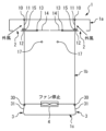
- FIG. 2 is a diagram for explaining the basic components that constitute the wind pressure shutter.
- the roof portion 1a is equipped with a wind pressure type shutter having a double configuration of an outer blade 11 (first door) and an inner blade 14 (second door).
- the first rotating shaft 10 is arranged horizontally downstream of the intake port 2 .
- the outer blade 11 (first door) is rotatably suspended from the first rotating shaft 10 .
- the outer blade 11 closes the flow path in the vertical position (rest position) and opens the flow path when rotated from the vertical position.
- the outer blades 11 are arranged to close the flow path in windless conditions.
- the outer blade 11 is a rectangular metal or synthetic resin plate.
- the first rotation preventing device 12 is provided on the roof portion 1a so as to prevent the outer blade 11 from rotating upstream from the vertical position.
- the first anti-rotation device 12 can prevent the outer blades 11 from opening due to a crosswind.
- the second rotating shaft 13 is arranged horizontally downstream of the outer blades 11 .
- the second rotating shaft 13 is provided at substantially the same height as the lower ends of the outer blades 11 in the vertical state.
- the inner blade 14 is rotatably attached to the second rotating shaft 13 .
- a portion of the inner blade 14 on the downstream side of the second rotating shaft 13 is 14a, and a portion of the inner blade 14 on the upstream side is 14b.
- the center of gravity of the inner blade 14 is located at the upstream portion 14b.
- the center of gravity of the inner blades 14 is adjusted so that the inner blades 14 are stable in a horizontal position when the cooling fan 4 is stopped, and the inner blades 14 rotate when the cooling fan 4 is in operation.
- the upstream portion 14b is supported by the bottom surface of the roof portion 1a in a horizontal state.
- a space between the roof portion 1a below the downstream portion 14a and the device housing portion 1b is open as a channel.
- the upstream end of the inner blade 14 (upstream portion 14b) has a stopper 15.
- the inner blade 14 closes the flow path between the roof portion 1a and the equipment storage portion 1b in a horizontal position. Further, the stopper 15 prevents the rotation of the outer blade 11 in the horizontal position of the inner blade 14 .
- the inner blade 14 opens the flow path at a position where the downstream portion 14a is rotated downward from the horizontal state.
- the inner blade 14 is a rectangular metal or synthetic resin plate.
- the second anti-rotation device 17 is provided so that the angle at which the inner blade 14 can be rotated is less than 90 degrees from horizontal. By limiting the rotatable angle of the inner blade 14 in this way, the inner blade 14 can be returned to the horizontal position by its own weight when the cooling fan 4 stops.
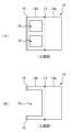
- FIG. 3 is a top view illustrating the inner blade 14.
- FIG. 3A shows an example of the inner blade 14.
- FIG. The upstream portion 14b has air intake holes 16 to allow the upstream portion 14b to function as part of the flow path.
- FIG. 3B shows another example of the inner blade 14.
- FIG. The intake holes 16 are arranged larger than those in FIG. 3A, and the stoppers 15 are arranged only at both ends in the width direction.
- negative pressure is generated downstream of the inner blades 14 when the cooling fan 4 operates.
- the air pressure in the channel of the equipment housing portion 1b is lower than the predetermined value compared to the air pressure in the channel of the roof portion 1a.
- FIG. 4 is a diagram showing the state of the wind pressure shutter before the cooling fan 4 starts operating.
- the inner blades 14 are stationary in a horizontal position to close the flow path.
- the outer blade 11 is stationary in a vertical position and closes the flow path.
- the upstream rotation of the outer blade 11 is restrained by the first rotation prevention tool 12
- the downstream rotation is restrained by the stopper 15 which is the upstream end of the inner blade 14 . Therefore, even if the outer blade 11 is pushed by a strong outside wind, the outer blade 11 can maintain the closed state.
- FIG. 5 is a diagram for explaining the operation of the wind pressure shutter after the cooling fan 4 starts operating.
- the inside of the equipment housing portion 1b becomes negative pressure, and the inner blade 14 rotates in the opening direction due to the pressure difference.
- the inner blade 14 rotates until it contacts the second anti-rotation device 17 .
- the stopper 15 is disengaged from the outer blade 11 as the inner blade 14 rotates.
- FIG. 6 is a diagram for explaining the operation of the wind pressure shutter after the cooling fan 4 starts operating.
- the stopper 15 holding the outer blade 11 comes off, the outer blade 11 also rotates in the opening direction due to the pressure difference.
- the flow path from the intake port 2 to the exhaust port 3 is opened, and outside air can be taken into the inside of the switchboard. Since the upstream portion 14b of the inner blade 14 has the air intake hole 16 as shown in FIG. 3, the inner blade 14 does not block ventilation in the state shown in FIG.
- FIG 7 and 8 are diagrams for explaining the operation of the wind pressure shutter when the cooling fan changes from the operating state to the stopped state.
- the cooling fan 4 stops the flow of air inside the housing 1 stops.
- the inner blade 14 and the outer blade 11 rotate in the closing direction under their own weight. Since the stopper 15 of the inner blade 14 pushes the outer blade 11, only the inner blade 14 is not closed.
- the wind pressure shutter according to the present embodiment when the fan is stopped, the outer blade 11 on the intake side is locked by the stopper 15 of the inner blade 14, so that the external wind is prevented. Even if it is strong, it can suppress the ingress of dust and water, and has high waterproof and dustproof properties.
- the wind pressure shutter according to the present embodiment is realized with a simple structure that works in conjunction with the operation of the fan, and the cost (manufacturing cost, maintenance cost) and failure risk are low.
- the wind pressure shutter according to this embodiment can prevent dust and moisture intrusion exceeding the allowable amount by stopping the switchboard (fan) when the environmental conditions are outside the specifications. Since the power conversion device for photovoltaic power generation operates in fine weather and often stops in bad weather, it is preferable as an application target of the wind pressure shutter according to the present embodiment.
- the inner blade 14 described above is provided with air intake holes 16 .
- the intake hole 16 may be covered with a dust filter. Having a dustproof filter can improve resistance to the environment.
Landscapes
- Engineering & Computer Science (AREA)
- Power Engineering (AREA)
- Microelectronics & Electronic Packaging (AREA)
- Mechanical Engineering (AREA)
- General Engineering & Computer Science (AREA)
- Physics & Mathematics (AREA)
- Thermal Sciences (AREA)
- Chemical & Material Sciences (AREA)
- Combustion & Propulsion (AREA)
- Patch Boards (AREA)
- Wind Motors (AREA)
- Cooling Or The Like Of Electrical Apparatus (AREA)
Priority Applications (4)
| Application Number | Priority Date | Filing Date | Title |
|---|---|---|---|
| US18/251,024 US12300976B2 (en) | 2021-10-22 | 2021-10-22 | Wind pressure type shutter for outdoor switchboard |
| JP2023521410A JP7392900B2 (ja) | 2021-10-22 | 2021-10-22 | 屋外配電盤のための風圧式シャッター |
| CN202180072620.4A CN116391302A (zh) | 2021-10-22 | 2021-10-22 | 用于室外配电盘的风压式挡板 |
| PCT/JP2021/039125 WO2023067804A1 (ja) | 2021-10-22 | 2021-10-22 | 屋外配電盤のための風圧式シャッター |
Applications Claiming Priority (1)
| Application Number | Priority Date | Filing Date | Title |
|---|---|---|---|
| PCT/JP2021/039125 WO2023067804A1 (ja) | 2021-10-22 | 2021-10-22 | 屋外配電盤のための風圧式シャッター |
Publications (1)
| Publication Number | Publication Date |
|---|---|
| WO2023067804A1 true WO2023067804A1 (ja) | 2023-04-27 |
Family
ID=86058075
Family Applications (1)
| Application Number | Title | Priority Date | Filing Date |
|---|---|---|---|
| PCT/JP2021/039125 Ceased WO2023067804A1 (ja) | 2021-10-22 | 2021-10-22 | 屋外配電盤のための風圧式シャッター |
Country Status (4)
| Country | Link |
|---|---|
| US (1) | US12300976B2 (https=) |
| JP (1) | JP7392900B2 (https=) |
| CN (1) | CN116391302A (https=) |
| WO (1) | WO2023067804A1 (https=) |
Families Citing this family (2)
| Publication number | Priority date | Publication date | Assignee | Title |
|---|---|---|---|---|
| CN114867314B (zh) * | 2022-05-20 | 2023-03-10 | 杭州市电力设计院有限公司 | 一种应用于精准送风控制的gis机柜 |
| CN120879361B (zh) * | 2025-09-25 | 2025-12-16 | 吉林省金仑科技有限公司 | 一种户外电力变电箱 |
Citations (4)
| Publication number | Priority date | Publication date | Assignee | Title |
|---|---|---|---|---|
| JPH08280106A (ja) * | 1995-04-10 | 1996-10-22 | Meidensha Corp | 配電盤の冷却装置 |
| JP2004128367A (ja) * | 2002-10-07 | 2004-04-22 | Meidensha Corp | 屋外盤 |
| JP2010142104A (ja) * | 2008-11-14 | 2010-06-24 | Yaskawa Electric Corp | 収納機器の固定構造および換気構造を備えた配電盤 |
| JP2012177501A (ja) * | 2011-02-25 | 2012-09-13 | Nitto Electric Works Ltd | 電気機器収納用箱の通風装置 |
Family Cites Families (8)
| Publication number | Priority date | Publication date | Assignee | Title |
|---|---|---|---|---|
| US1532635A (en) * | 1924-02-21 | 1925-04-07 | Osbun Justin Edward | Ceiling ventilator |
| GB485850A (en) * | 1938-01-21 | 1938-05-25 | Derek Richard Barker | Improvements in and relating to shutters for use with blower ventilating fans |
| US3286732A (en) * | 1963-02-04 | 1966-11-22 | American Warming Ventilation | Flow control damper |
| US4766807A (en) * | 1987-08-27 | 1988-08-30 | American Standard Inc. | Damper blade seal |
| US6181557B1 (en) * | 1999-10-29 | 2001-01-30 | Motorola, Inc. | Electronic component, method of cooling, and damper therefor |
| US8899066B2 (en) * | 2011-09-07 | 2014-12-02 | General Electric Company | System for environmental protection of a heat exchanger |
| JP2017200298A (ja) | 2016-04-26 | 2017-11-02 | 株式会社東芝 | 屋外配電盤 |
| JP6854362B1 (ja) * | 2019-04-24 | 2021-04-07 | 東芝三菱電機産業システム株式会社 | 換気装置、換気ユニットおよび電力変換装置 |
-
2021
- 2021-10-22 US US18/251,024 patent/US12300976B2/en active Active
- 2021-10-22 JP JP2023521410A patent/JP7392900B2/ja active Active
- 2021-10-22 WO PCT/JP2021/039125 patent/WO2023067804A1/ja not_active Ceased
- 2021-10-22 CN CN202180072620.4A patent/CN116391302A/zh active Pending
Patent Citations (4)
| Publication number | Priority date | Publication date | Assignee | Title |
|---|---|---|---|---|
| JPH08280106A (ja) * | 1995-04-10 | 1996-10-22 | Meidensha Corp | 配電盤の冷却装置 |
| JP2004128367A (ja) * | 2002-10-07 | 2004-04-22 | Meidensha Corp | 屋外盤 |
| JP2010142104A (ja) * | 2008-11-14 | 2010-06-24 | Yaskawa Electric Corp | 収納機器の固定構造および換気構造を備えた配電盤 |
| JP2012177501A (ja) * | 2011-02-25 | 2012-09-13 | Nitto Electric Works Ltd | 電気機器収納用箱の通風装置 |
Also Published As
| Publication number | Publication date |
|---|---|
| JPWO2023067804A1 (https=) | 2023-04-27 |
| US20240332919A1 (en) | 2024-10-03 |
| JP7392900B2 (ja) | 2023-12-06 |
| CN116391302A (zh) | 2023-07-04 |
| US12300976B2 (en) | 2025-05-13 |
Similar Documents
| Publication | Publication Date | Title |
|---|---|---|
| JP7392900B2 (ja) | 屋外配電盤のための風圧式シャッター | |
| JP5856472B2 (ja) | 蓄電池の設置構造 | |
| US20120107085A1 (en) | Housing and Mass Airflow Rate Control System for a Wind Turbine | |
| US10644484B2 (en) | Arc resistant exhaust and intake for drives and switchgear | |
| CN104377937A (zh) | 室外变频柜 | |
| JP2012177501A (ja) | 電気機器収納用箱の通風装置 | |
| TWM653449U (zh) | 百葉窗之外罩結構 | |
| CN208127098U (zh) | 一种刀闸机构箱防雨罩 | |
| CN115498518A (zh) | 一种用于电网系统的野外电力室 | |
| CN214941746U (zh) | 一种房顶可拆的密闭钢结构房体 | |
| CN210985344U (zh) | 一种保护效果好的机电用控制箱 | |
| CN212876504U (zh) | 一种通信机柜通风降温系统 | |
| KR101066785B1 (ko) | 비닐하우스용 배기장치 | |
| JP2586791Y2 (ja) | 電子機器筐体の冷却装置 | |
| CN223124400U (zh) | 一种防雨淋的电气自动化电气盒 | |
| CN213367048U (zh) | 一种室外防水隔热配电柜 | |
| CN222301153U (zh) | 一种公路配套建设用高原型开关柜设备 | |
| KR102626995B1 (ko) | 환기시스템의 역풍방지 전동댐퍼유닛 | |
| CN204258595U (zh) | 室外变频柜 | |
| CN221784463U (zh) | 用于变频抽油机的自然风冷式控制柜 | |
| CN221726500U (zh) | 一种单向自动闭合通风窗结构 | |
| CN219459205U (zh) | 一种建筑用监控装置 | |
| CN216121453U (zh) | 配电柜散热监测系统 | |
| CN201351641Y (zh) | 风机防回流装置 | |
| TWI844418B (zh) | 具防護風門的戶外型機櫃 |
Legal Events
| Date | Code | Title | Description |
|---|---|---|---|
| WWE | Wipo information: entry into national phase |
Ref document number: 2023521410 Country of ref document: JP |
|
| WWE | Wipo information: entry into national phase |
Ref document number: 202317029810 Country of ref document: IN |
|
| WWE | Wipo information: entry into national phase |
Ref document number: 18251024 Country of ref document: US |
|
| 121 | Ep: the epo has been informed by wipo that ep was designated in this application |
Ref document number: 21961452 Country of ref document: EP Kind code of ref document: A1 |
|
| NENP | Non-entry into the national phase |
Ref country code: DE |
|
| 122 | Ep: pct application non-entry in european phase |
Ref document number: 21961452 Country of ref document: EP Kind code of ref document: A1 |
|
| WWG | Wipo information: grant in national office |
Ref document number: 18251024 Country of ref document: US |