WO2023067804A1 - Wind pressure shutter for outddor distribution board - Google Patents
Wind pressure shutter for outddor distribution board Download PDFInfo
- Publication number
- WO2023067804A1 WO2023067804A1 PCT/JP2021/039125 JP2021039125W WO2023067804A1 WO 2023067804 A1 WO2023067804 A1 WO 2023067804A1 JP 2021039125 W JP2021039125 W JP 2021039125W WO 2023067804 A1 WO2023067804 A1 WO 2023067804A1
- Authority
- WO
- WIPO (PCT)
- Prior art keywords
- door
- flow path
- wind pressure
- shutter
- downstream
- Prior art date
Links
- 238000011144 upstream manufacturing Methods 0.000 claims abstract description 18
- 239000000428 dust Substances 0.000 claims abstract description 11
- 230000005484 gravity Effects 0.000 claims description 4
- 238000001816 cooling Methods 0.000 description 19
- 238000010586 diagram Methods 0.000 description 11
- XLYOFNOQVPJJNP-UHFFFAOYSA-N water Substances O XLYOFNOQVPJJNP-UHFFFAOYSA-N 0.000 description 4
- 238000006243 chemical reaction Methods 0.000 description 3
- 238000010248 power generation Methods 0.000 description 3
- 230000002265 prevention Effects 0.000 description 3
- 238000012423 maintenance Methods 0.000 description 2
- 238000004519 manufacturing process Methods 0.000 description 2
- 239000002184 metal Substances 0.000 description 2
- 238000000034 method Methods 0.000 description 2
- 238000012986 modification Methods 0.000 description 2
- 230000004048 modification Effects 0.000 description 2
- 229920003002 synthetic resin Polymers 0.000 description 2
- 239000000057 synthetic resin Substances 0.000 description 2
- 230000002159 abnormal effect Effects 0.000 description 1
- 230000009977 dual effect Effects 0.000 description 1
- 230000000694 effects Effects 0.000 description 1
- 238000005516 engineering process Methods 0.000 description 1
- 230000007613 environmental effect Effects 0.000 description 1
- 238000009423 ventilation Methods 0.000 description 1
Images


Classifications
-
- H—ELECTRICITY
- H02—GENERATION; CONVERSION OR DISTRIBUTION OF ELECTRIC POWER
- H02B—BOARDS, SUBSTATIONS OR SWITCHING ARRANGEMENTS FOR THE SUPPLY OR DISTRIBUTION OF ELECTRIC POWER
- H02B1/00—Frameworks, boards, panels, desks, casings; Details of substations or switching arrangements
- H02B1/56—Cooling; Ventilation
Definitions
- the present disclosure relates to wind pressure shutters for outdoor switchboards.
- power conversion equipment for photovoltaic power generation installed outdoors adopts a method that actively takes in outside air and cools it with a heat sink, etc., in order to improve price competitiveness and increase equipment capacity.
- Patent Document 1 discloses a technique for determining abnormal weather using an external sensor and electrically controlling a shutter to close an intake port.
- Patent Document 1 requires a control device to drive the sensor and the shutter, and the cost and failure risk are high. It is desirable to be able to solve the problem with only a simple configuration that does not require sensors or controllers.
- FIG. 9A a wind pressure type shutter in which the intake side blade 91 opens only inward and the exhaust side blade 92 opens only outward is conceivable.
- this wind pressure type shutter when the cooling fan 90 is driven, the suction side blade 91 opens inward due to the negative pressure, and the sucked air is pushed out to open the exhaust side blade 92 outward ((B) in FIG. 9). ).
- the wind pressure shutter as shown in FIG. 9 has a simple structure and is excellent in terms of cost. It could not be provided on the intake side where the intake direction is the same.
- the present disclosure has been made to solve the above-described problems, and provides a wind pressure type shutter for an outdoor switchboard that has high waterproof and dustproof properties during a storm and that is low in cost and failure risk. With the goal.
- the first aspect relates to pneumatic shutters for outdoor switchboards.
- the outdoor switchboard has a flow path for exhausting the gas sucked from the intake port from the exhaust port.
- the wind pressure shutter includes a first rotating shaft, a first door, a second rotating shaft and a second door.
- the first rotating shaft is horizontally arranged downstream of the air inlet.
- the first door is rotatably suspended on the first rotating shaft.
- the first door closes the flow path in a vertical position.
- the first door opens the channel at a position rotated from the vertical position.
- a said 2nd rotating shaft is horizontally arrange
- the second door is rotatably attached to the second rotating shaft.
- the second door closes the flow path in a horizontal position, and its upstream end restrains the rotation of the first door.
- the second door opens the channel at a position rotated from the horizontal position.
- a negative pressure is generated downstream of the second door, the second door rotates to open the flow path, the upstream end is separated from the first door, and the first door moves downstream to open the channel.
- the second aspect further has the following features in addition to the first aspect.
- the center of gravity of the second door is located closer to the first door than the second rotating shaft.
- the third aspect further has the following features in addition to the first or second aspect.
- a said 2nd door has an air intake hole in a said 1st door side rather than a said 2nd rotating shaft.
- the fourth aspect further has the following features in addition to any one of the first to third aspects.
- the intake hole is covered with a dust filter.
- the fifth aspect further has the following features in addition to any one of the first to fourth aspects.
- the outdoor switchboard has a fan that creates a negative pressure downstream of the second door.
- the sixth aspect further has the following features in addition to any one of the first to fifth aspects.
- the angle through which the second door can be rotated is less than 90 degrees from the horizontal position.
- the seventh aspect further has the following features in addition to any one of the first to sixth aspects.
- the first door is rotatable only in a downstream direction from a vertical position.
- the wind pressure shutter according to the present disclosure is waterproof even when the outside wind is strong because the outer door (first door) on the intake side is locked with the inner door (second door) when the switchboard is not in operation. and highly dust resistant.
- the pneumatic shutter has a simple structure, low cost (manufacturing cost, maintenance cost) and failure risk.
- This wind pressure type shutter is suitable for application to the intake section of a power converter for photovoltaic power generation, which is installed outdoors and is not operated during stormy weather.
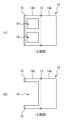
- FIG. 1 is a diagram for explaining a configuration example of an outdoor switchboard according to an embodiment.
- the outdoor switchboard is, for example, a photovoltaic power converter installed outdoors.
- the housing 1 of the outdoor switchboard consists of a roof section 1a, an equipment storage section 1b, and a floor section 1c in order from the top.
- the intake port 2 is formed in the eaves of the roof portion 1a to prevent rain and dust from entering.
- a heat source for example, a power conversion device (not shown) and a cooling fan 4 for cooling the heat source are arranged in the device housing portion 1b.
- the cooling fan 4 is installed between the equipment storage portion 1b and the underfloor portion 1c, and discharges gas in the equipment storage portion 1b to the underfloor portion 1c.
- An exhaust port 3 is formed in the lower floor 1c.
- a third rotating shaft 30 is horizontally arranged above the exhaust port 3 .
- the exhaust blade 31 is suspended from the third rotating shaft 30 and can only rotate outward.
- the housing 1 has a flow path for exhausting gas sucked from the intake port 2 from the exhaust port 3 .
- a wind pressure type shutter is arranged in the flow path from the intake port 2 of the roof portion 1a to the equipment housing portion 1b.
- a heat source, a cooling fan 4, and a power supply (not shown) for supplying power to the heat source and the cooling fan 4 are arranged in the flow path from the equipment housing portion 1b to the underfloor portion 1c.
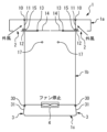
- FIG. 2 is a diagram for explaining the basic components that constitute the wind pressure shutter.
- the roof portion 1a is equipped with a wind pressure type shutter having a double configuration of an outer blade 11 (first door) and an inner blade 14 (second door).
- the first rotating shaft 10 is arranged horizontally downstream of the intake port 2 .
- the outer blade 11 (first door) is rotatably suspended from the first rotating shaft 10 .
- the outer blade 11 closes the flow path in the vertical position (rest position) and opens the flow path when rotated from the vertical position.
- the outer blades 11 are arranged to close the flow path in windless conditions.
- the outer blade 11 is a rectangular metal or synthetic resin plate.
- the first rotation preventing device 12 is provided on the roof portion 1a so as to prevent the outer blade 11 from rotating upstream from the vertical position.
- the first anti-rotation device 12 can prevent the outer blades 11 from opening due to a crosswind.
- the second rotating shaft 13 is arranged horizontally downstream of the outer blades 11 .
- the second rotating shaft 13 is provided at substantially the same height as the lower ends of the outer blades 11 in the vertical state.
- the inner blade 14 is rotatably attached to the second rotating shaft 13 .
- a portion of the inner blade 14 on the downstream side of the second rotating shaft 13 is 14a, and a portion of the inner blade 14 on the upstream side is 14b.
- the center of gravity of the inner blade 14 is located at the upstream portion 14b.
- the center of gravity of the inner blades 14 is adjusted so that the inner blades 14 are stable in a horizontal position when the cooling fan 4 is stopped, and the inner blades 14 rotate when the cooling fan 4 is in operation.
- the upstream portion 14b is supported by the bottom surface of the roof portion 1a in a horizontal state.
- a space between the roof portion 1a below the downstream portion 14a and the device housing portion 1b is open as a channel.
- the upstream end of the inner blade 14 (upstream portion 14b) has a stopper 15.
- the inner blade 14 closes the flow path between the roof portion 1a and the equipment storage portion 1b in a horizontal position. Further, the stopper 15 prevents the rotation of the outer blade 11 in the horizontal position of the inner blade 14 .
- the inner blade 14 opens the flow path at a position where the downstream portion 14a is rotated downward from the horizontal state.
- the inner blade 14 is a rectangular metal or synthetic resin plate.
- the second anti-rotation device 17 is provided so that the angle at which the inner blade 14 can be rotated is less than 90 degrees from horizontal. By limiting the rotatable angle of the inner blade 14 in this way, the inner blade 14 can be returned to the horizontal position by its own weight when the cooling fan 4 stops.
- FIG. 3 is a top view illustrating the inner blade 14.
- FIG. 3A shows an example of the inner blade 14.
- FIG. The upstream portion 14b has air intake holes 16 to allow the upstream portion 14b to function as part of the flow path.
- FIG. 3B shows another example of the inner blade 14.
- FIG. The intake holes 16 are arranged larger than those in FIG. 3A, and the stoppers 15 are arranged only at both ends in the width direction.
- negative pressure is generated downstream of the inner blades 14 when the cooling fan 4 operates.
- the air pressure in the channel of the equipment housing portion 1b is lower than the predetermined value compared to the air pressure in the channel of the roof portion 1a.
- FIG. 4 is a diagram showing the state of the wind pressure shutter before the cooling fan 4 starts operating.
- the inner blades 14 are stationary in a horizontal position to close the flow path.
- the outer blade 11 is stationary in a vertical position and closes the flow path.
- the upstream rotation of the outer blade 11 is restrained by the first rotation prevention tool 12
- the downstream rotation is restrained by the stopper 15 which is the upstream end of the inner blade 14 . Therefore, even if the outer blade 11 is pushed by a strong outside wind, the outer blade 11 can maintain the closed state.
- FIG. 5 is a diagram for explaining the operation of the wind pressure shutter after the cooling fan 4 starts operating.
- the inside of the equipment housing portion 1b becomes negative pressure, and the inner blade 14 rotates in the opening direction due to the pressure difference.
- the inner blade 14 rotates until it contacts the second anti-rotation device 17 .
- the stopper 15 is disengaged from the outer blade 11 as the inner blade 14 rotates.
- FIG. 6 is a diagram for explaining the operation of the wind pressure shutter after the cooling fan 4 starts operating.
- the stopper 15 holding the outer blade 11 comes off, the outer blade 11 also rotates in the opening direction due to the pressure difference.
- the flow path from the intake port 2 to the exhaust port 3 is opened, and outside air can be taken into the inside of the switchboard. Since the upstream portion 14b of the inner blade 14 has the air intake hole 16 as shown in FIG. 3, the inner blade 14 does not block ventilation in the state shown in FIG.
- FIG 7 and 8 are diagrams for explaining the operation of the wind pressure shutter when the cooling fan changes from the operating state to the stopped state.
- the cooling fan 4 stops the flow of air inside the housing 1 stops.
- the inner blade 14 and the outer blade 11 rotate in the closing direction under their own weight. Since the stopper 15 of the inner blade 14 pushes the outer blade 11, only the inner blade 14 is not closed.
- the wind pressure shutter according to the present embodiment when the fan is stopped, the outer blade 11 on the intake side is locked by the stopper 15 of the inner blade 14, so that the external wind is prevented. Even if it is strong, it can suppress the ingress of dust and water, and has high waterproof and dustproof properties.
- the wind pressure shutter according to the present embodiment is realized with a simple structure that works in conjunction with the operation of the fan, and the cost (manufacturing cost, maintenance cost) and failure risk are low.
- the wind pressure shutter according to this embodiment can prevent dust and moisture intrusion exceeding the allowable amount by stopping the switchboard (fan) when the environmental conditions are outside the specifications. Since the power conversion device for photovoltaic power generation operates in fine weather and often stops in bad weather, it is preferable as an application target of the wind pressure shutter according to the present embodiment.
- the inner blade 14 described above is provided with air intake holes 16 .
- the intake hole 16 may be covered with a dust filter. Having a dustproof filter can improve resistance to the environment.
Landscapes
- Engineering & Computer Science (AREA)
- Power Engineering (AREA)
- Patch Boards (AREA)
- Cooling Or The Like Of Electrical Apparatus (AREA)
- Wind Motors (AREA)
Abstract
Provided is a wind pressure shutter having a high waterproof property and a high dust resistance during storm, a low cost, and a low failure risk. The wind pressure shutter comprises a first rotation shaft, a first door, a second rotation shaft, and a second door. The first door is rotatably suspended from the first rotation shaft, closes a flow path at a vertical position, and opens the flow path at a position rotated from the vertical position. The second door is rotatably attached to the second rotation shaft, closes the flow path and allows the upstream side end portion thereof to prevent the first door from rotating at a horizontal position, and opens the flow path at a position rotated from the horizontal position. When a negative pressure occurs in the downstream from the second door, the second door rotates to open the flow path, the upstream side end portion departs from the first door, and then the first door rotates to the downstream side to open the flow path.
Description
本開示は、屋外配電盤のための風圧式シャッターに関する。
The present disclosure relates to wind pressure shutters for outdoor switchboards.
一般的に、屋外に設置される太陽光発電用電力変換装置には、価格競争力向上および装置容量向上のために、外気を積極的に取り込んでヒートシンク等で冷却する方式が採用されている。
In general, power conversion equipment for photovoltaic power generation installed outdoors adopts a method that actively takes in outside air and cools it with a heat sink, etc., in order to improve price competitiveness and increase equipment capacity.
外気を積極的に取り込む一方で、装置内への塵埃や水分(雨・雪など)の浸入を抑制することは重要である。近年では集中豪雨、台風、暴風雪が増加しており、装置内に想定を超える量の水分が浸入することによる故障リスクも高まってきている。
通風量の確保と防塵性・防水性を両立するために吸排気口にシャッターを設けることは有効な手段である。 It is important to prevent dust and moisture (rain, snow, etc.) from entering the device while positively taking in outside air. In recent years, torrential rains, typhoons, and blizzards have increased, and the risk of failure due to the intrusion of an unexpected amount of water into the equipment has also increased.
It is an effective means to provide a shutter at the air intake/exhaust port in order to ensure both airflow and dust/water resistance.
例えば、このような問題に対して、特許文献1には、外部センサを用いて異常気象を判断し、シャッターを電気的に制御して吸気口を閉じる技術が開示されている。
For example, in order to address such a problem, Patent Document 1 discloses a technique for determining abnormal weather using an external sensor and electrically controlling a shutter to close an intake port.
しかしながら、特許文献1の技術ではセンサやシャッターを駆動する制御装置が必要であり、コストや故障リスクが高い。センサや制御装置を必要としない単純な構成のみで、問題を解決できることが望ましい。
However, the technology of Patent Document 1 requires a control device to drive the sensor and the shutter, and the cost and failure risk are high. It is desirable to be able to solve the problem with only a simple configuration that does not require sensors or controllers.
このような問題に対して、例えば図9の(A)に示すように、吸気側ブレード91が内側にのみ開き、排気側ブレード92が外側にのみ開く風圧式シャッターが考えられる。この風圧式シャッターは、冷却ファン90が駆動した場合に、負圧により吸気側ブレード91が内側に開き、吸気された空気が押し出されて排気側ブレード92が外側に開く(図9の(B))。
As a solution to this problem, for example, as shown in FIG. 9A, a wind pressure type shutter in which the intake side blade 91 opens only inward and the exhaust side blade 92 opens only outward is conceivable. In this wind pressure type shutter, when the cooling fan 90 is driven, the suction side blade 91 opens inward due to the negative pressure, and the sucked air is pushed out to open the exhaust side blade 92 outward ((B) in FIG. 9). ).
しかしながら、図9の(C)に示すように、吸気側に想定を超える強い外風が当たれば、吸気側ブレード91が内側に開き、内部へ水や塵が侵入するおそれがある。そのため、荒天時の対策が十分とは言えない。
However, as shown in FIG. 9C, if the intake side is hit by an unexpectedly strong outside wind, the intake side blades 91 may open inward, allowing water and dust to enter the interior. Therefore, it cannot be said that measures against stormy weather are sufficient.
図9に示すような風圧式シャッターは、構造が簡素でコスト面で優れているが、吸気側ブレード91が外風に押されることで開くため、外風による塵埃・水分の浸入方向と装置の吸気方向が一致する吸気側に設けることはできなかった。
The wind pressure shutter as shown in FIG. 9 has a simple structure and is excellent in terms of cost. It could not be provided on the intake side where the intake direction is the same.
本開示は、上述のような課題を解決するためになされたもので、暴風時における防水性および防塵性が高く、かつ、コストおよび故障リスクの低い屋外配電盤のための風圧式シャッターを提供することを目的とする。
The present disclosure has been made to solve the above-described problems, and provides a wind pressure type shutter for an outdoor switchboard that has high waterproof and dustproof properties during a storm and that is low in cost and failure risk. With the goal.
第1の観点は、屋外配電盤のための風圧式シャッターに関連する。
前記屋外配電盤は、吸気口から吸気された気体を排気口から排気するための流路を有する。
前記風圧式シャッターは、第1回転軸と第1扉と第2回転軸と第2扉とを備える。
前記第1回転軸は、前記吸気口の下流に、水平に配置される。
前記第1扉は、前記第1回転軸に回転可能に吊り下げられる。前記第1扉は、鉛直位置で前記流路を閉じる。前記第1扉は、前記鉛直位置から回転した位置で前記流路を開く。
前記第2回転軸は、前記第1扉よりも下流に、水平に配置される。
前記第2扉は、前記第2回転軸に回転可能に取り付けられる。前記第2扉は、水平位置で前記流路を閉じると共にその上流側端部が前記第1扉の回転を抑止する。前記第2扉は、前記水平位置から回転した位置で前記流路を開く。
前記第2扉よりも下流に負圧が生じた場合に、前記第2扉が回転して前記流路を開くと共に前記上流側端部が前記第1扉から外れ、前記第1扉が下流側に回転して前記流路を開く。 The first aspect relates to pneumatic shutters for outdoor switchboards.
The outdoor switchboard has a flow path for exhausting the gas sucked from the intake port from the exhaust port.
The wind pressure shutter includes a first rotating shaft, a first door, a second rotating shaft and a second door.
The first rotating shaft is horizontally arranged downstream of the air inlet.
The first door is rotatably suspended on the first rotating shaft. The first door closes the flow path in a vertical position. The first door opens the channel at a position rotated from the vertical position.
A said 2nd rotating shaft is horizontally arrange|positioned downstream rather than a said 1st door.
The second door is rotatably attached to the second rotating shaft. The second door closes the flow path in a horizontal position, and its upstream end restrains the rotation of the first door. The second door opens the channel at a position rotated from the horizontal position.
When a negative pressure is generated downstream of the second door, the second door rotates to open the flow path, the upstream end is separated from the first door, and the first door moves downstream to open the channel.
第2の観点は、第1の観点に加えて、次の特徴を更に有する。
前記第2扉の重心は、前記第2回転軸よりも前記第1扉側に位置する。 The second aspect further has the following features in addition to the first aspect.
The center of gravity of the second door is located closer to the first door than the second rotating shaft.
前記第2扉の重心は、前記第2回転軸よりも前記第1扉側に位置する。 The second aspect further has the following features in addition to the first aspect.
The center of gravity of the second door is located closer to the first door than the second rotating shaft.
第3の観点は、第1又は2の観点に加えて、次の特徴を更に有する。
前記第2扉は、前記第2回転軸よりも前記第1扉側に吸気穴を有する。 The third aspect further has the following features in addition to the first or second aspect.
A said 2nd door has an air intake hole in a said 1st door side rather than a said 2nd rotating shaft.
前記第2扉は、前記第2回転軸よりも前記第1扉側に吸気穴を有する。 The third aspect further has the following features in addition to the first or second aspect.
A said 2nd door has an air intake hole in a said 1st door side rather than a said 2nd rotating shaft.
第4の観点は、第1乃至第3の観点のいずれかに加えて、次の特徴を更に有する。
前記吸気穴は、防塵フィルタで覆われている。 The fourth aspect further has the following features in addition to any one of the first to third aspects.
The intake hole is covered with a dust filter.
前記吸気穴は、防塵フィルタで覆われている。 The fourth aspect further has the following features in addition to any one of the first to third aspects.
The intake hole is covered with a dust filter.
第5の観点は、第1乃至第4の観点のいずれかに加えて、次の特徴を更に有する。
前記屋外配電盤は、前記第2扉よりも下流に負圧を生じさせるファンを有する。 The fifth aspect further has the following features in addition to any one of the first to fourth aspects.
The outdoor switchboard has a fan that creates a negative pressure downstream of the second door.
前記屋外配電盤は、前記第2扉よりも下流に負圧を生じさせるファンを有する。 The fifth aspect further has the following features in addition to any one of the first to fourth aspects.
The outdoor switchboard has a fan that creates a negative pressure downstream of the second door.
第6の観点は、第1乃至第5の観点のいずれかに加えて、次の特徴を更に有する。
前記第2扉が回転可能な角度は、水平位置から90度未満までである。 The sixth aspect further has the following features in addition to any one of the first to fifth aspects.
The angle through which the second door can be rotated is less than 90 degrees from the horizontal position.
前記第2扉が回転可能な角度は、水平位置から90度未満までである。 The sixth aspect further has the following features in addition to any one of the first to fifth aspects.
The angle through which the second door can be rotated is less than 90 degrees from the horizontal position.
第7の観点は、第1乃至第6の観点のいずれかに加えて、次の特徴を更に有する。
前記第1扉は、鉛直位置から下流方向にのみ回転可能である。 The seventh aspect further has the following features in addition to any one of the first to sixth aspects.
The first door is rotatable only in a downstream direction from a vertical position.
前記第1扉は、鉛直位置から下流方向にのみ回転可能である。 The seventh aspect further has the following features in addition to any one of the first to sixth aspects.
The first door is rotatable only in a downstream direction from a vertical position.
本開示に係る風圧式シャッターは、配電盤の非運転時において吸気側の外扉(第1扉)が内扉(第2扉)でロックされるため、外風が強い場合であっても防水性および防塵性が高い。加えて、本風圧式シャッターは、単純な構造で実現され、コスト(製造コスト、メンテナンスコスト)および故障リスクが低い。本風圧式シャッターは、荒天時は運転しない屋外に設置される太陽光発電用電力変換装置の吸気部への適用に好適である。
The wind pressure shutter according to the present disclosure is waterproof even when the outside wind is strong because the outer door (first door) on the intake side is locked with the inner door (second door) when the switchboard is not in operation. and highly dust resistant. In addition, the pneumatic shutter has a simple structure, low cost (manufacturing cost, maintenance cost) and failure risk. This wind pressure type shutter is suitable for application to the intake section of a power converter for photovoltaic power generation, which is installed outdoors and is not operated during stormy weather.
以下、図面を参照して本開示の実施の形態について詳細に説明する。尚、各図において共通する要素には、同一の符号を付して重複する説明を省略する。
Hereinafter, embodiments of the present disclosure will be described in detail with reference to the drawings. Elements that are common in each drawing are denoted by the same reference numerals, and overlapping descriptions are omitted.
実施の形態.
1.屋外配電盤
図1は、実施の形態に係る屋外配電盤の構成例について説明するための図である。屋外配電盤は、例えば屋外に設置される太陽光発電用電力変換装置である。 Embodiment.
1. Outdoor Switchboard FIG. 1 is a diagram for explaining a configuration example of an outdoor switchboard according to an embodiment. The outdoor switchboard is, for example, a photovoltaic power converter installed outdoors.
屋外配電盤の筐体1は、上から順に屋根部1aと機器収納部1bと床下部1cからなる。吸気口2は、雨や塵の侵入を抑制するために屋根部1aのひさしに形成されている。機器収納部1bには、図示省略する熱源(例えば電力変換装置)と、当該熱源を冷却するための冷却ファン4が配置されている。冷却ファン4は、機器収納部1bと床下部1cとの間に設置され、機器収納部1b内の気体を床下部1cへ排出する。床下部1cには、排気口3が形成されている。排気口3の上部には第3回転軸30が水平に配置されている。排気ブレード31は、第3回転軸30に吊り下げられ、外側へのみ回転可能である。
The housing 1 of the outdoor switchboard consists of a roof section 1a, an equipment storage section 1b, and a floor section 1c in order from the top. The intake port 2 is formed in the eaves of the roof portion 1a to prevent rain and dust from entering. A heat source (for example, a power conversion device) (not shown) and a cooling fan 4 for cooling the heat source are arranged in the device housing portion 1b. The cooling fan 4 is installed between the equipment storage portion 1b and the underfloor portion 1c, and discharges gas in the equipment storage portion 1b to the underfloor portion 1c. An exhaust port 3 is formed in the lower floor 1c. A third rotating shaft 30 is horizontally arranged above the exhaust port 3 . The exhaust blade 31 is suspended from the third rotating shaft 30 and can only rotate outward.
筐体1は、吸気口2から吸気された気体を排気口3から排気するための流路を有する。屋根部1aの吸気口2から機器収納部1bまでの流路には、風圧式シャッターが配置されている。機器収納部1bから床下部1cまでの流路には、熱源、冷却ファン4、および熱源と冷却ファン4へ電力を供給する電源(図示省略)が配置されている。
The housing 1 has a flow path for exhausting gas sucked from the intake port 2 from the exhaust port 3 . A wind pressure type shutter is arranged in the flow path from the intake port 2 of the roof portion 1a to the equipment housing portion 1b. A heat source, a cooling fan 4, and a power supply (not shown) for supplying power to the heat source and the cooling fan 4 are arranged in the flow path from the equipment housing portion 1b to the underfloor portion 1c.
2.風圧式シャッターの構成
次に図1および図2を参照して、本実施の形態に係る風圧式シャッターの構成について説明する。図2は、風圧式シャッターを構成する基本部品について説明するための図である。屋根部1aは、外側ブレード11(第1扉)と内側ブレード14(第2扉)の二重構成の風圧式シャッターを備える。 2. Configuration of Wind Pressure Shutter Next, the configuration of the wind pressure shutter according to the present embodiment will be described with reference to FIGS. 1 and 2. FIG. FIG. 2 is a diagram for explaining the basic components that constitute the wind pressure shutter. Theroof portion 1a is equipped with a wind pressure type shutter having a double configuration of an outer blade 11 (first door) and an inner blade 14 (second door).
次に図1および図2を参照して、本実施の形態に係る風圧式シャッターの構成について説明する。図2は、風圧式シャッターを構成する基本部品について説明するための図である。屋根部1aは、外側ブレード11(第1扉)と内側ブレード14(第2扉)の二重構成の風圧式シャッターを備える。 2. Configuration of Wind Pressure Shutter Next, the configuration of the wind pressure shutter according to the present embodiment will be described with reference to FIGS. 1 and 2. FIG. FIG. 2 is a diagram for explaining the basic components that constitute the wind pressure shutter. The
(外側ブレード)
第1回転軸10は、吸気口2の下流に、水平に配置されている。外側ブレード11(第1扉)は、第1回転軸10に回転可能に吊り下げられている。外側ブレード11は、鉛直位置(静止位置)で流路を閉じ、鉛直位置から回転した状態で流路を開く。外側ブレード11は、無風状態で流路を閉じるように調整されている。外側ブレード11は、矩形の金属または合成樹脂の板である。第1回転防止具12は、外側ブレード11が鉛直位置から上流側へ回転することを抑止するように屋根部1aに設けられる。第1回転防止具12によれば、横風の舞い上がりにより外側ブレード11が開くことを防止できる。 (outer blade)
The firstrotating shaft 10 is arranged horizontally downstream of the intake port 2 . The outer blade 11 (first door) is rotatably suspended from the first rotating shaft 10 . The outer blade 11 closes the flow path in the vertical position (rest position) and opens the flow path when rotated from the vertical position. The outer blades 11 are arranged to close the flow path in windless conditions. The outer blade 11 is a rectangular metal or synthetic resin plate. The first rotation preventing device 12 is provided on the roof portion 1a so as to prevent the outer blade 11 from rotating upstream from the vertical position. The first anti-rotation device 12 can prevent the outer blades 11 from opening due to a crosswind.
第1回転軸10は、吸気口2の下流に、水平に配置されている。外側ブレード11(第1扉)は、第1回転軸10に回転可能に吊り下げられている。外側ブレード11は、鉛直位置(静止位置)で流路を閉じ、鉛直位置から回転した状態で流路を開く。外側ブレード11は、無風状態で流路を閉じるように調整されている。外側ブレード11は、矩形の金属または合成樹脂の板である。第1回転防止具12は、外側ブレード11が鉛直位置から上流側へ回転することを抑止するように屋根部1aに設けられる。第1回転防止具12によれば、横風の舞い上がりにより外側ブレード11が開くことを防止できる。 (outer blade)
The first
(内側ブレード)
第2回転軸13は、外側ブレード11よりも下流に、水平に配置されている。第2回転軸13は、鉛直状態の外側ブレード11の下端と略同じ高さに設けられている。内側ブレード14は、第2回転軸13に回転可能に取り付けられている。内側ブレード14の第2回転軸13よりも下流側の部分を14a、上流側の部分を14bとする。内側ブレード14の重心は、上流側部分14bに位置する。内側ブレード14の重心は、冷却ファン4の停止時に内側ブレード14が水平位置で安定し、冷却ファン4の運転時に内側ブレード14が回転するように調整されている。上流側部分14bは、水平な状態において屋根部1aの底面に支えられる。下流側部分14aの下方の屋根部1aと機器収納部1bとの間は流路として開口している。 (inner blade)
The secondrotating shaft 13 is arranged horizontally downstream of the outer blades 11 . The second rotating shaft 13 is provided at substantially the same height as the lower ends of the outer blades 11 in the vertical state. The inner blade 14 is rotatably attached to the second rotating shaft 13 . A portion of the inner blade 14 on the downstream side of the second rotating shaft 13 is 14a, and a portion of the inner blade 14 on the upstream side is 14b. The center of gravity of the inner blade 14 is located at the upstream portion 14b. The center of gravity of the inner blades 14 is adjusted so that the inner blades 14 are stable in a horizontal position when the cooling fan 4 is stopped, and the inner blades 14 rotate when the cooling fan 4 is in operation. The upstream portion 14b is supported by the bottom surface of the roof portion 1a in a horizontal state. A space between the roof portion 1a below the downstream portion 14a and the device housing portion 1b is open as a channel.
第2回転軸13は、外側ブレード11よりも下流に、水平に配置されている。第2回転軸13は、鉛直状態の外側ブレード11の下端と略同じ高さに設けられている。内側ブレード14は、第2回転軸13に回転可能に取り付けられている。内側ブレード14の第2回転軸13よりも下流側の部分を14a、上流側の部分を14bとする。内側ブレード14の重心は、上流側部分14bに位置する。内側ブレード14の重心は、冷却ファン4の停止時に内側ブレード14が水平位置で安定し、冷却ファン4の運転時に内側ブレード14が回転するように調整されている。上流側部分14bは、水平な状態において屋根部1aの底面に支えられる。下流側部分14aの下方の屋根部1aと機器収納部1bとの間は流路として開口している。 (inner blade)
The second
内側ブレード14(上流側部分14b)の上流側端部は、ストッパー15を有する。内側ブレード14は、水平位置で屋根部1aと機器収納部1bとの間の流路を閉じる。また、内側ブレード14は、水平位置でストッパー15が外側ブレード11の回転を抑止する。内側ブレード14は、水平状態から下流側部分14aが下方向に回転した位置で流路を開く。内側ブレード14は、矩形の金属または合成樹脂の板である。第2回転防止具17は、内側ブレード14が回転可能な角度が水平位置から90度未満となるように設けられている。このように内側ブレード14の回転可能角度を制限することで、冷却ファン4の停止時に自重により内側ブレード14を水平位置に戻すことができる。
The upstream end of the inner blade 14 (upstream portion 14b) has a stopper 15. The inner blade 14 closes the flow path between the roof portion 1a and the equipment storage portion 1b in a horizontal position. Further, the stopper 15 prevents the rotation of the outer blade 11 in the horizontal position of the inner blade 14 . The inner blade 14 opens the flow path at a position where the downstream portion 14a is rotated downward from the horizontal state. The inner blade 14 is a rectangular metal or synthetic resin plate. The second anti-rotation device 17 is provided so that the angle at which the inner blade 14 can be rotated is less than 90 degrees from horizontal. By limiting the rotatable angle of the inner blade 14 in this way, the inner blade 14 can be returned to the horizontal position by its own weight when the cooling fan 4 stops.
図3は、内側ブレード14を例示する上面図である。図3の(A)は内側ブレード14の一例を示す。上流側部分14bを流路の一部として機能させるために、上流側部分14bは吸気穴16を有する。図3の(B)は内側ブレード14の他の例を示す。図3の(A)に比して吸気穴16は大きく配置され、ストッパー15は幅方向の両端部にのみ配置される。
FIG. 3 is a top view illustrating the inner blade 14. FIG. FIG. 3A shows an example of the inner blade 14. FIG. The upstream portion 14b has air intake holes 16 to allow the upstream portion 14b to function as part of the flow path. FIG. 3B shows another example of the inner blade 14. FIG. The intake holes 16 are arranged larger than those in FIG. 3A, and the stoppers 15 are arranged only at both ends in the width direction.
このような構成において、冷却ファン4が運転すると内側ブレード14よりも下流に負圧が生じる。具体的には、屋根部1aの流路の気圧に比して機器収納部1bの流路の気圧が所定値よりも低くなる。内側ブレード14よりも下流に負圧が生じた場合に、内側ブレード14が回転して流路を開くと共にストッパー15が外側ブレード11から外れ、内側ブレード14が下流側に回転して流路を開く。
In such a configuration, negative pressure is generated downstream of the inner blades 14 when the cooling fan 4 operates. Specifically, the air pressure in the channel of the equipment housing portion 1b is lower than the predetermined value compared to the air pressure in the channel of the roof portion 1a. When negative pressure is generated downstream of the inner blade 14, the inner blade 14 rotates to open the flow path, the stopper 15 is disengaged from the outer blade 11, and the inner blade 14 rotates downstream to open the flow path. .
3.風圧式シャッターの動作
次に、冷却ファン4の運転状態に応じた風圧式シャッターの動作について説明する。
図4は、冷却ファン4の運転を開始する前の風圧式シャッターの状態を示す図である。ファン停止時には、内側ブレード14は水平位置で静止して流路を閉じている。外側ブレード11は、鉛直位置において静止して流路を閉じている。このとき、外側ブレード11の上流側への回転は第1回転防止具12により抑止され、下流側への回転は内側ブレード14の上流側端部であるストッパー15により抑止される。そのため、強い外風によって外側ブレード11が押されたとしても、外側ブレード11は閉状態を維持できる。 3. Pneumatic shutter operation
Next, the operation of the wind pressure shutter according to the operating state of the coolingfan 4 will be described.
FIG. 4 is a diagram showing the state of the wind pressure shutter before the coolingfan 4 starts operating. When the fan is stopped, the inner blades 14 are stationary in a horizontal position to close the flow path. The outer blade 11 is stationary in a vertical position and closes the flow path. At this time, the upstream rotation of the outer blade 11 is restrained by the first rotation prevention tool 12 , and the downstream rotation is restrained by the stopper 15 which is the upstream end of the inner blade 14 . Therefore, even if the outer blade 11 is pushed by a strong outside wind, the outer blade 11 can maintain the closed state.
次に、冷却ファン4の運転状態に応じた風圧式シャッターの動作について説明する。
図4は、冷却ファン4の運転を開始する前の風圧式シャッターの状態を示す図である。ファン停止時には、内側ブレード14は水平位置で静止して流路を閉じている。外側ブレード11は、鉛直位置において静止して流路を閉じている。このとき、外側ブレード11の上流側への回転は第1回転防止具12により抑止され、下流側への回転は内側ブレード14の上流側端部であるストッパー15により抑止される。そのため、強い外風によって外側ブレード11が押されたとしても、外側ブレード11は閉状態を維持できる。 3. Pneumatic shutter operation
Next, the operation of the wind pressure shutter according to the operating state of the cooling
FIG. 4 is a diagram showing the state of the wind pressure shutter before the cooling
図5は、冷却ファン4が運転を開始した後の風圧式シャッターの動作を説明するための図である。冷却ファン4が運転を開始すると機器収納部1bの内部が負圧になり、圧力差によって内側ブレード14が開方向に回転する。内側ブレード14は、第2回転防止具17に接触するまで回転する。このとき、内側ブレード14の回転に伴って、ストッパー15が外側ブレード11から外れる。
FIG. 5 is a diagram for explaining the operation of the wind pressure shutter after the cooling fan 4 starts operating. When the cooling fan 4 starts operating, the inside of the equipment housing portion 1b becomes negative pressure, and the inner blade 14 rotates in the opening direction due to the pressure difference. The inner blade 14 rotates until it contacts the second anti-rotation device 17 . At this time, the stopper 15 is disengaged from the outer blade 11 as the inner blade 14 rotates.
図6は、冷却ファン4が運転を開始した後の風圧式シャッターの動作を説明するための図である。外側ブレード11を押さえていたストッパー15が外れると、外側ブレード11も圧力差で開方向に回転する。これにより、吸気口2から排気口3までの流路が開き、配電盤の内部に外気を取り込むことが可能になる。なお、上述した図3に示すように内側ブレード14の上流側部分14bは吸気穴16を有するため、図6に示す状態において内側ブレード14は通風を妨げない。
FIG. 6 is a diagram for explaining the operation of the wind pressure shutter after the cooling fan 4 starts operating. When the stopper 15 holding the outer blade 11 comes off, the outer blade 11 also rotates in the opening direction due to the pressure difference. As a result, the flow path from the intake port 2 to the exhaust port 3 is opened, and outside air can be taken into the inside of the switchboard. Since the upstream portion 14b of the inner blade 14 has the air intake hole 16 as shown in FIG. 3, the inner blade 14 does not block ventilation in the state shown in FIG.
図7および図8は、冷却ファンが運転状態から停止状態に変化した場合の風圧式シャッターの動作を説明するための図である。冷却ファン4が停止すると筐体1内の風の流れが止まる。風が止まることで内側ブレード14および外側ブレード11が自重で閉方向に回転する。内側ブレード14のストッパー15が外側ブレード11を押すので、内側ブレード14のみが閉まることはない。
7 and 8 are diagrams for explaining the operation of the wind pressure shutter when the cooling fan changes from the operating state to the stopped state. When the cooling fan 4 stops, the flow of air inside the housing 1 stops. When the wind stops, the inner blade 14 and the outer blade 11 rotate in the closing direction under their own weight. Since the stopper 15 of the inner blade 14 pushes the outer blade 11, only the inner blade 14 is not closed.
4.効果
以上説明したように、本実施の形態に係る二重構成の風圧式シャッターによれば、ファン停止時において吸気側の外側ブレード11が内側ブレード14のストッパー15でロックされるため、外風が強い場合であっても塵埃・水分の浸入を抑制でき、防水性および防塵性が高い。加えて、本実施の形態に係る風圧式シャッターは、ファンの動作に連動する単純な構造で実現され、コスト(製造コスト、メンテナンスコスト)および故障リスクが低い。また、通常、暴風雨・暴風雪への対策を装置内部で処置するには内部の防水性を向上させることが必要であるが、本風圧式シャッターであれば吸気部の対策のみで対応できるため、費用対効果が大きい。 4. Effect As described above, according to the dual wind pressure shutter according to the present embodiment, when the fan is stopped, theouter blade 11 on the intake side is locked by the stopper 15 of the inner blade 14, so that the external wind is prevented. Even if it is strong, it can suppress the ingress of dust and water, and has high waterproof and dustproof properties. In addition, the wind pressure shutter according to the present embodiment is realized with a simple structure that works in conjunction with the operation of the fan, and the cost (manufacturing cost, maintenance cost) and failure risk are low. In addition, normally, it is necessary to improve the internal waterproofness in order to take countermeasures against storms and snowstorms inside the device, but with this wind pressure type shutter, it is possible to deal with it only by taking countermeasures for the intake part, so it is less costly. Highly effective.
以上説明したように、本実施の形態に係る二重構成の風圧式シャッターによれば、ファン停止時において吸気側の外側ブレード11が内側ブレード14のストッパー15でロックされるため、外風が強い場合であっても塵埃・水分の浸入を抑制でき、防水性および防塵性が高い。加えて、本実施の形態に係る風圧式シャッターは、ファンの動作に連動する単純な構造で実現され、コスト(製造コスト、メンテナンスコスト)および故障リスクが低い。また、通常、暴風雨・暴風雪への対策を装置内部で処置するには内部の防水性を向上させることが必要であるが、本風圧式シャッターであれば吸気部の対策のみで対応できるため、費用対効果が大きい。 4. Effect As described above, according to the dual wind pressure shutter according to the present embodiment, when the fan is stopped, the
本実施の形態に係る風圧式シャッターは、仕様外の環境条件となる場合に、配電盤(ファン)を停止することで、許容量を超える塵埃・水分浸入を防ぐことができる。太陽光発電用電力変換装置は晴天時に稼働し、悪天候時に停止することが多いため、本実施の形態に係る風圧式シャッターの適用対象として好ましい。
The wind pressure shutter according to this embodiment can prevent dust and moisture intrusion exceeding the allowable amount by stopping the switchboard (fan) when the environmental conditions are outside the specifications. Since the power conversion device for photovoltaic power generation operates in fine weather and often stops in bad weather, it is preferable as an application target of the wind pressure shutter according to the present embodiment.
5.変形例
ところで、上述した内側ブレード14は、吸気穴16を備えている。吸気穴16は、防塵フィルタで覆われていることとしてもよい。防塵フィルタを有することで対環境性を高めることができる。 5. Modifications By the way, theinner blade 14 described above is provided with air intake holes 16 . The intake hole 16 may be covered with a dust filter. Having a dustproof filter can improve resistance to the environment.
ところで、上述した内側ブレード14は、吸気穴16を備えている。吸気穴16は、防塵フィルタで覆われていることとしてもよい。防塵フィルタを有することで対環境性を高めることができる。 5. Modifications By the way, the
以上、本開示の実施の形態について説明したが、本開示は、上記の実施の形態に限定されるものではなく、本開示の趣旨を逸脱しない範囲で種々変形して実施することができる。上述した実施の形態において各要素の個数、数量、量、範囲等の数に言及した場合、特に明示した場合や原理的に明らかにその数に特定される場合を除いて、その言及した数にこの開示が限定されるものではない。また、上述した実施の形態において説明する構造等は、特に明示した場合や明らかに原理的にそれに特定される場合を除いて、この開示に必ずしも必須のものではない。
Although the embodiments of the present disclosure have been described above, the present disclosure is not limited to the above-described embodiments, and various modifications can be made without departing from the scope of the present disclosure. When referring to numbers such as the number, quantity, amount, range, etc. of each element in the above-described embodiments, unless otherwise specified or clearly specified in principle, the number referred to This disclosure is not intended to be limiting. Also, the structures and the like described in the above-described embodiments are not necessarily essential to this disclosure, unless otherwise specified or clearly specified in principle.
1 筐体
1a 屋根部
1b 機器収納部
1c 床下部
2 吸気口
3 排気口
4 冷却ファン
10 第1回転軸
11 外側ブレード
12 第1回転防止具
13 第2回転軸
14 内側ブレード
14a 下流側部分
14b 上流側部分
15 ストッパー
16 吸気穴
17 第2回転防止具
30 第3回転軸
31 排気ブレード
90 冷却ファン
91 吸気側ブレード
92 排気側ブレード 1 Case 1a Roof 1b Equipment storage 1c Underfloor 2 Intake port 3 Exhaust port 4 Cooling fan 10 First rotating shaft 11 Outer blade 12 First rotation prevention tool 13 Second rotating shaft 14 Inner blade 14a Downstream part 14b Upstream Side portion 15 Stopper 16 Air intake hole 17 Second rotation prevention tool 30 Third rotating shaft 31 Exhaust blade 90 Cooling fan 91 Intake side blade 92 Exhaust side blade
1a 屋根部
1b 機器収納部
1c 床下部
2 吸気口
3 排気口
4 冷却ファン
10 第1回転軸
11 外側ブレード
12 第1回転防止具
13 第2回転軸
14 内側ブレード
14a 下流側部分
14b 上流側部分
15 ストッパー
16 吸気穴
17 第2回転防止具
30 第3回転軸
31 排気ブレード
90 冷却ファン
91 吸気側ブレード
92 排気側ブレード 1
Claims (7)
- 吸気口から吸気された気体を排気口から排気するための流路を有する屋外配電盤のための風圧式シャッターであって、
前記吸気口の下流に、水平に配置された第1回転軸と、
前記第1回転軸に回転可能に吊り下げられ、鉛直位置で前記流路を閉じ、前記鉛直位置から回転した位置で前記流路を開く第1扉と、
前記第1扉よりも下流に、水平に配置された第2回転軸と、
前記第2回転軸に回転可能に取り付けられ、水平位置で前記流路を閉じると共に上流側端部が前記第1扉の回転を抑止し、前記水平位置から回転した位置で前記流路を開く第2扉と、を備え、
前記第2扉よりも下流に負圧が生じた場合に、前記第2扉が回転して前記流路を開くと共に前記上流側端部が前記第1扉から外れ、前記第1扉が下流側に回転して前記流路を開くこと、
を特徴とする屋外配電盤のための風圧式シャッター。 A wind pressure shutter for an outdoor switchboard having a flow path for exhausting gas sucked from an intake port from an exhaust port,
a first rotating shaft arranged horizontally downstream of the air inlet;
a first door that is rotatably suspended from the first rotating shaft, closes the flow path at a vertical position, and opens the flow path at a position rotated from the vertical position;
a second rotating shaft arranged horizontally downstream of the first door;
The second door is rotatably attached to the second rotating shaft, closes the flow path in a horizontal position, and has an upstream end that prevents rotation of the first door and opens the flow path in a position rotated from the horizontal position. 2 doors;
When negative pressure is generated downstream of the second door, the second door rotates to open the flow path, the upstream end is separated from the first door, and the first door moves downstream rotating to open the channel;
A pneumatic shutter for an outdoor switchboard characterized by - 前記第2扉の重心は、前記第2回転軸よりも前記第1扉側に位置すること、
を特徴とする請求項1に記載の屋外配電盤のための風圧式シャッター。 the center of gravity of the second door is positioned closer to the first door than the second rotation axis;
The wind pressure shutter for outdoor switchboard according to claim 1, characterized by: - 前記第2扉は、前記第2回転軸よりも前記第1扉側に吸気穴を有すること、
を特徴とする請求項1又は2に記載の屋外配電盤のための風圧式シャッター。 the second door has an intake hole on the first door side of the second rotating shaft;
The wind pressure shutter for outdoor switchboard according to claim 1 or 2, characterized in that: - 前記吸気穴は、防塵フィルタで覆われていること、
を特徴とする請求項3に記載の屋外配電盤のための風圧式シャッター。 The intake hole is covered with a dust filter;
The wind pressure shutter for outdoor switchboard according to claim 3, characterized in that. - 前記屋外配電盤は、前記第2扉よりも下流に負圧を生じさせるファンを有すること、
を特徴とする請求項1乃至4のいずれか1項に記載の屋外配電盤のための風圧式シャッター。 The outdoor switchboard has a fan that creates a negative pressure downstream of the second door;
The wind pressure shutter for an outdoor switchboard according to any one of claims 1 to 4, characterized in that: - 前記第2扉が回転可能な角度は、水平位置から90度未満までであること、
を特徴とする請求項1乃至5のいずれか1項に記載の屋外配電盤のための風圧式シャッター。 the angle by which the second door can be rotated is less than 90 degrees from a horizontal position;
The wind pressure shutter for an outdoor switchboard according to any one of claims 1 to 5, characterized in that: - 前記第1扉は、鉛直位置から下流方向にのみ回転可能であること、
を特徴とする請求項1乃至6のいずれか1項に記載の屋外配電盤のための風圧式シャッター。 the first door is rotatable only in a downstream direction from a vertical position;
The wind pressure shutter for an outdoor switchboard according to any one of claims 1 to 6, characterized in that:
Priority Applications (3)
| Application Number | Priority Date | Filing Date | Title |
|---|---|---|---|
| JP2023521410A JP7392900B2 (en) | 2021-10-22 | 2021-10-22 | Wind pressure shutter for outdoor switchboard |
| CN202180072620.4A CN116391302A (en) | 2021-10-22 | 2021-10-22 | Wind pressure type baffle for outdoor distribution board |
| PCT/JP2021/039125 WO2023067804A1 (en) | 2021-10-22 | 2021-10-22 | Wind pressure shutter for outddor distribution board |
Applications Claiming Priority (1)
| Application Number | Priority Date | Filing Date | Title |
|---|---|---|---|
| PCT/JP2021/039125 WO2023067804A1 (en) | 2021-10-22 | 2021-10-22 | Wind pressure shutter for outddor distribution board |
Publications (1)
| Publication Number | Publication Date |
|---|---|
| WO2023067804A1 true WO2023067804A1 (en) | 2023-04-27 |
Family
ID=86058075
Family Applications (1)
| Application Number | Title | Priority Date | Filing Date |
|---|---|---|---|
| PCT/JP2021/039125 WO2023067804A1 (en) | 2021-10-22 | 2021-10-22 | Wind pressure shutter for outddor distribution board |
Country Status (3)
| Country | Link |
|---|---|
| JP (1) | JP7392900B2 (en) |
| CN (1) | CN116391302A (en) |
| WO (1) | WO2023067804A1 (en) |
Citations (4)
| Publication number | Priority date | Publication date | Assignee | Title |
|---|---|---|---|---|
| JPH08280106A (en) * | 1995-04-10 | 1996-10-22 | Meidensha Corp | Cooling apparatus of power distribution board |
| JP2004128367A (en) * | 2002-10-07 | 2004-04-22 | Meidensha Corp | Outdoor panel |
| JP2010142104A (en) * | 2008-11-14 | 2010-06-24 | Yaskawa Electric Corp | Fixing structure of storage apparatus and switchboard including exhaust structure |
| JP2012177501A (en) * | 2011-02-25 | 2012-09-13 | Nitto Electric Works Ltd | Ventilation device of box for storing electrical equipment |
-
2021
- 2021-10-22 JP JP2023521410A patent/JP7392900B2/en active Active
- 2021-10-22 WO PCT/JP2021/039125 patent/WO2023067804A1/en active Application Filing
- 2021-10-22 CN CN202180072620.4A patent/CN116391302A/en active Pending
Patent Citations (4)
| Publication number | Priority date | Publication date | Assignee | Title |
|---|---|---|---|---|
| JPH08280106A (en) * | 1995-04-10 | 1996-10-22 | Meidensha Corp | Cooling apparatus of power distribution board |
| JP2004128367A (en) * | 2002-10-07 | 2004-04-22 | Meidensha Corp | Outdoor panel |
| JP2010142104A (en) * | 2008-11-14 | 2010-06-24 | Yaskawa Electric Corp | Fixing structure of storage apparatus and switchboard including exhaust structure |
| JP2012177501A (en) * | 2011-02-25 | 2012-09-13 | Nitto Electric Works Ltd | Ventilation device of box for storing electrical equipment |
Also Published As
| Publication number | Publication date |
|---|---|
| JP7392900B2 (en) | 2023-12-06 |
| CN116391302A (en) | 2023-07-04 |
| JPWO2023067804A1 (en) | 2023-04-27 |
Similar Documents
| Publication | Publication Date | Title |
|---|---|---|
| CN101632332B (en) | Cooling device | |
| US7731477B2 (en) | Insulated housing apparatus for use with an attic fan | |
| US8702383B2 (en) | Switchgear cabinet for a wind turbine | |
| JP5856472B2 (en) | Storage battery installation structure | |
| CN201144844Y (en) | Air flow control structure for heat radiation fan | |
| CA3053377C (en) | Arc resistant exhaust and intake for drives and switchgear | |
| WO2023067804A1 (en) | Wind pressure shutter for outddor distribution board | |
| JP2011012613A (en) | Air conditioner | |
| JP4735451B2 (en) | Ventilated building | |
| GB2482129A (en) | Roof ventilation louvre having upward passages with concave upper surface | |
| CN204191059U (en) | Air port grid are put | |
| CN214204526U (en) | Municipal outdoor power distribution cabinet | |
| JP2012177501A (en) | Ventilation device of box for storing electrical equipment | |
| KR101066785B1 (en) | An air exhauster for a plastic greenfouse | |
| KR102254576B1 (en) | Exhaust cover for air conditioner outdoor unit | |
| CN109579214B (en) | Method for actively ventilating indoor by using corridor wind energy | |
| JP2586791Y2 (en) | Cooling device for electronic equipment housing | |
| CN213367048U (en) | Outdoor waterproof thermal-insulated switch board | |
| CN201351641Y (en) | Fan anti-return device | |
| CN218795716U (en) | Ventilation cover plate for fan system of urea prilling tower | |
| CN214589754U (en) | Electrical cabinet | |
| CN210659438U (en) | Intelligent machine room | |
| CN216390095U (en) | Intelligent dual-power-supply automatic switching low-voltage cabinet based on big data platform | |
| CN207927092U (en) | A kind of two-phase stepping motor controller group water proof and dust proof shell | |
| CN218839124U (en) | Energy storage device and energy storage vehicle |
Legal Events
| Date | Code | Title | Description |
|---|---|---|---|
| WWE | Wipo information: entry into national phase |
Ref document number: 2023521410 Country of ref document: JP |
|
| 121 | Ep: the epo has been informed by wipo that ep was designated in this application |
Ref document number: 21961452 Country of ref document: EP Kind code of ref document: A1 |