JP2012177501A - Ventilation device of box for storing electrical equipment - Google Patents
Ventilation device of box for storing electrical equipment Download PDFInfo
- Publication number
- JP2012177501A JP2012177501A JP2011040129A JP2011040129A JP2012177501A JP 2012177501 A JP2012177501 A JP 2012177501A JP 2011040129 A JP2011040129 A JP 2011040129A JP 2011040129 A JP2011040129 A JP 2011040129A JP 2012177501 A JP2012177501 A JP 2012177501A
- Authority
- JP
- Japan
- Prior art keywords
- shutter
- attached
- exhaust port
- weight
- storage box
- Prior art date
- Legal status (The legal status is an assumption and is not a legal conclusion. Google has not performed a legal analysis and makes no representation as to the accuracy of the status listed.)
- Pending
Links
Images


Abstract
Description
本発明は、電気機器収納用箱内の熱気を排気するための通風装置に関する。 The present invention relates to a ventilating device for exhausting hot air in an electric equipment storage box.
分電機器、配電機器、通信装置等の電気機器を収納する電気機器収納用箱には、内部機器の熱気を排気するために、特許文献1に示されるように、ファンを電気機器収納用箱に取り付けたものがある。或いは、吸気口及び排気口が形成された筐体内にファンが取り付けられた通風装置を電気機器収納用箱の外面に取り付けた構造のものもある。収納される電気機器の発熱を考慮した電気機器の配置や電気機器収納用箱の種類によって、前記通風装置は、排気口を横方向に向けた横向き姿勢で前記箱の天井面に取り付けられ、或いは、排気口を下方に向けた縦向き姿勢で前記箱の側面に取り付けられる。 An electrical equipment storage box for storing electrical equipment such as power distribution equipment, power distribution equipment, and communication devices has a fan as shown in Patent Document 1 for exhausting hot air from the internal equipment. There is something attached to. Alternatively, there is a structure in which a ventilation device in which a fan is attached in a housing in which an intake port and an exhaust port are formed is attached to an outer surface of an electric equipment storage box. Depending on the arrangement of the electric equipment considering the heat generation of the electric equipment to be stored and the type of the electric equipment storage box, the ventilator is attached to the ceiling surface of the box in a lateral orientation with the exhaust port directed laterally, or And attached to the side of the box in a vertical orientation with the exhaust port facing downward.
通風装置が取り付けられた電気機器収納用箱を屋外で使用する場合には、排気口から通風装置内への雨水や虫、埃等の異物の進入を防止する構造を設ける必要がある。この構造の一例として、従来では、排気口を閉塞するシャッターを通風装置に回動可能に軸着し、シャッターを排気口側に付勢する捲回バネをシャッターの軸部に取り付けていた。このような構成により、通風装置は、横向き又は縦向きのいずれの姿勢であっても、ファン稼働時には風圧によりシャッターが回動して排気口が開放され、ファン停止時には捲回バネの付勢力により、排気口がシャッターで閉塞され、ファン停止時の通風装置や電気機器収納用箱内への異物の進入が防止される。 When the electric equipment storage box to which the ventilation device is attached is used outdoors, it is necessary to provide a structure that prevents the entry of foreign matter such as rainwater, insects, and dust from the exhaust port into the ventilation device. As an example of this structure, conventionally, a shutter that closes the exhaust port is pivotally attached to the ventilation device, and a winding spring that urges the shutter toward the exhaust port is attached to the shaft portion of the shutter. With such a configuration, in the ventilation device, regardless of the horizontal or vertical orientation, the shutter is rotated by the wind pressure to open the exhaust port when the fan is operating, and the exhaust spring is biased when the fan is stopped. The exhaust port is blocked by a shutter, and foreign matter can be prevented from entering the ventilation device and the electric device storage box when the fan is stopped.
しかしながら、捲回バネのシャッターの軸部への取り付けは、作業性が悪く、屋外使用による捲回バネへの異物の付着や、シャッターの繰り返しの開閉による捲回バネのヘタリや破損により、ファン停止時に排気口がシャッターで閉塞されないという問題があった。
本発明は、上記問題を解決し、バネを用いることなく、ファン停止時に排気口が閉塞される電気機器収納用箱の通風装置を提供することを目的とする。
However, the installation of the winding spring on the shaft part of the shutter is poor in workability, and the fan stops due to foreign matter adhering to the winding spring due to outdoor use, or the winding spring becoming damaged or damaged due to repeated opening and closing of the shutter. There was a problem that sometimes the exhaust port was not blocked by the shutter.
An object of the present invention is to solve the above problems and to provide a ventilation device for an electric equipment storage box in which an exhaust port is closed when a fan is stopped without using a spring.
上記課題を解決するためになされた請求項1に記載の発明は、
電気機器収納用箱の天井面又は側面のいずれにも取付可能で、前記天井面又は前記側面に形成された排気穴から前記箱内部の空気を外部に排出する通風装置であって、
底面に吸入口が形成されるとともに、側方に開放する排気口が形成された箱形の筐体と、
前記筐体内に取り付けられ、前記吸入口からの吸気を前記排気口から排気させるファンと、
前記排気口を閉塞するように、前記筐体に回動可能に取り付けられた板状のシャッターと、
前記シャッターの回動軸から前記シャッターと反対側方向に延出する延出片と、
前記延出片に取り付けられた重りを有し、
前記側面に形成された排気穴と前記吸入口を連通させ、前記排気口を下側に向けた縦向きの姿勢で前記側面に取り付けた場合には、前記延出片及び前記重りの質量により生じる前記回動軸回りのモーメントのほうが、前記シャッターの質量により生じる前記回動軸回りのモーメントよりも大きく構成されていることを特徴とする。
The invention according to claim 1, which has been made to solve the above problems,
A ventilation device that can be attached to either a ceiling surface or a side surface of an electrical equipment storage box and exhausts air inside the box to the outside from an exhaust hole formed in the ceiling surface or the side surface,
A box-shaped housing having a suction port formed on the bottom surface and an exhaust port opening to the side;
A fan attached to the housing and exhausting the intake air from the intake port through the exhaust port;
A plate-like shutter rotatably attached to the housing so as to close the exhaust port;
An extending piece extending in a direction opposite to the shutter from the rotation axis of the shutter;
Having a weight attached to the extension piece;
When the exhaust hole formed in the side surface communicates with the suction port, and the exhaust port is attached to the side surface in a vertically oriented posture facing downward, it is generated by the mass of the extension piece and the weight. The moment around the rotation axis is configured to be larger than the moment around the rotation axis caused by the mass of the shutter.
請求項2に記載の発明は、請求項1に記載の発明において、
前記天井面に形成された排気穴と前記吸入口を連通させ、前記排気口を横側に向けた横向き姿勢で前記天井面に取り付けた場合よりも、前記縦向き姿勢で前記側面に取り付けた場合のほうが、前記シャッターの回動軸と前記重りの重心との水平方向距離が大きくなるように構成されていることを特徴とする。
これにより、縦向きの姿勢では、重りの重心と回動軸との水平方向距離が大きくなることから、重りによりシャッターが閉じる方向に作用するモーメントが大きくなり、シャッターが確実に排気口を閉塞する。
The invention according to claim 2 is the invention according to claim 1,
When the exhaust hole formed in the ceiling surface communicates with the suction port, and when the exhaust port is attached to the side surface in the vertical orientation, rather than being attached to the ceiling surface in a lateral orientation with the lateral side facing This is characterized in that the horizontal distance between the rotation axis of the shutter and the center of gravity of the weight is increased.
As a result, in the vertical orientation, the horizontal distance between the center of gravity of the weight and the rotating shaft increases, so the moment acting in the direction in which the shutter closes due to the weight increases, and the shutter reliably closes the exhaust port. .
請求項3に記載の発明は、請求項1又は請求項2に記載の発明において、
前記シャッターは、前記排気口の上方位置の筐体に回動可能に取り付けられ、
前記延出片は、前記シャッターの回動軸から上方に延出し、
前記重りは前記延出片の外側に取り付けられていることを特徴とする。
The invention according to claim 3 is the invention according to claim 1 or 2,
The shutter is rotatably attached to a housing above the exhaust port,
The extension piece extends upward from the rotation axis of the shutter,
The weight is attached to the outside of the extension piece.
請求項4に記載の発明は、請求項3に記載の発明において、
前記重りは、前記延出片に回動可能に取り付けられていることを特徴とする。
The invention according to claim 4 is the invention according to claim 3,
The weight is rotatably attached to the extension piece.
請求項5に記載の発明は、請求項1又は請求項2に記載の発明において、
前記シャッターは、前記排気口の下方位置の筐体に回動可能に取り付けられ、
前記延出片は、前記シャッターの回動軸から下方に延出していることを特徴とする。
The invention according to claim 5 is the invention according to claim 1 or 2,
The shutter is rotatably attached to a housing below the exhaust port,
The extending piece extends downward from a rotation axis of the shutter.
本発明によれば、前記排気口を下側に向けた縦向きの姿勢で前記側面に取り付けた場合には、前記延出片及び前記重りの質量により生じる前記回動軸回りのモーメントのほうが、前記シャッターの質量により生じる前記回動軸回りのモーメントよりも大きく構成されているので、シャッターが排気口を閉塞した状態が維持される。このため、電気機器収納用箱の天井面と側面のいずれに取り付けた場合であっても、バネを用いることなく、ファン停止時に排気口が閉塞される電気機器収納用箱の通風装置を提供することが可能となる。 According to the present invention, when the exhaust port is attached to the side surface in a vertically oriented posture facing downward, the moment around the rotation axis generated by the mass of the extension piece and the weight is more Since the moment around the rotation axis generated by the mass of the shutter is larger, the state where the shutter closes the exhaust port is maintained. For this reason, even if it is a case where it is a case where it is a case where it attaches to either the ceiling surface or side surface of an electric equipment storage box, the ventilation apparatus of the electric equipment storage box with which an exhaust port is obstruct | occluded at the time of a fan stop is provided, without using a spring. It becomes possible.
(第1の実施形態の電気機器収納用箱の通風装置)
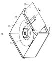
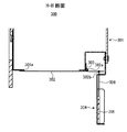
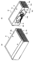
図1〜図9に第1の実施形態の電気機器収納用箱の通風装置100(以下、通風装置100とする)を示して、通風装置100について説明する。なお、図1、図3〜図5は、通風装置100を、横向きの姿勢で、電気機器収納用箱99の天井面に取り付けた状態を表した図である。図1、図3〜図5に示されるように、通風装置100は、筐体101、ファン10、シャッター102、重り103、ヒンジ104、105とから構成されている。
(Ventilation device for electrical equipment storage box according to the first embodiment)
1 to 9 show a ventilation device 100 (hereinafter, referred to as a ventilation device 100) for an electric device storage box according to the first embodiment, and the
筐体101は箱形形状であり、側方に開口する排気口101aが形成されている。なお、図1や図4において、筐体101の内部が見えるように、便宜的に天井面を除去した状態の筐体101を表しているが、筐体101は天井面101c(図3、図5に示す)を有している。図2に示されるように、筐体101の底面には、吸入口101bが形成されている。電気機器収納用箱99の天井面又は側面(背面を含む)には排気穴が形成され、前記排気穴と吸気口101bが連通して、通気装置100が電気機器収納用箱99の天井面又は側面に取り付けられる。筐体101内には、ファン10が取り付けられている。ファン10には、プロペラファン、シロッコファン、ターボファン等のファンが含まれる。ファン10が稼働すると、電気機器収納用箱99内の空気が、電気機器収納用箱99の排気穴(吸入口101b)から筐体101内に吸気され、排気口101aから排気される。
The
図3に示されるように、排気口101aの上方位置の筐体101には、排気口101aを閉塞する板状のシャッター102がヒンジ104により回動可能に取り付けられている。図3に示されるように、シャッター102は、その上端の第1回動軸102aで、筐体101に軸着されている。図3に示されるように、シャッター102の第1回動軸102aからは、上方に延出する延出片102cが形成されている。
As shown in FIG. 3, a plate-
図3に示されるように、延出片102c先端の外側の第2回動軸102bには、板状又はブロック状の重り103がヒンジ105により回動可能に軸着している。なお、シャッター102はアルミニウムや樹脂等の比重が軽い材質で構成されているが、重り103は鉄や鉛等、シャッター102に比べて比重が重い材料で構成されている。
As shown in FIG. 3, a plate-like or block-
以下に、図1、図3〜図5を用いて、排気口101aを横側に向けた横向き姿勢で、通風装置100を電気機器収納用箱99の天井面に取り付けた場合の作用について説明する。
ファン10が停止している状態では、図1や図3に示されるように、シャッター102の自重により、シャッター102が排気口101aを閉塞している。この状態では、シャッター102に重り103の重量も作用するので、排気口101aがシャッター102で確実に閉塞され、風によるシャッター102の開放が防止され、排気口101aからの異物の進入が防止される。
一方で、ファン10が稼働している状態では、図4や図5に示されるように、ファン10で発生する風圧により、シャッター102が第1回動軸102aを中心に回動して、排気口101aが開放される。
Hereinafter, the operation when the
In the state where the
On the other hand, when the
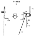
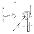
図6〜図9は、排気口101aを下側に向けた縦向きの姿勢で、通風装置100を電気機器収納用箱99の側面に取り付けた状態を示した図である。以下に、図6〜図9を用いて、縦向きの姿勢で、通風装置100を電気機器収納用箱99の側面に取り付けた場合の作用について説明する。
ファン10が停止している状態では、図6や図7に示されるように、重り103の重量により、シャッター102が排気口101aを閉塞する方向に回動され、排気口101aがシャッター102で閉塞される。詳述すると、通風装置100が縦向きの姿勢では、延出片102c及び重り103の質量により生じる第1回動軸102a回りのモーメントのほうが、シャッター102の質量により生じる第1回動軸102a回りのモーメントよりも大きいので、シャッター102が排気口101aを閉塞した状態が維持される。
一方で、ファン10が稼働している状態では、図8や図9に示されるように、ファン10で発生する風圧により、シャッター102が第1回動軸102aを中心に回動して、排気口101aが開放される。
6-9 is the figure which showed the state which attached the
When the
On the other hand, when the
通風装置100を、横向きの姿勢で、電気機器収納用箱99の天井面に取り付けた状態では、図3や図5に示されるように、重り103の重心と第1回動軸102aの水平方向距離AやA’は小さい。このため、ファン10稼働時において、重り103によりシャッター102が閉じる方向に作用するモーメントは小さく、シャッター102の開放の阻害となりにくい。
一方で、通風装置100を、縦向き姿勢で、電気機器収納用箱99の側面に取り付けた状態では、図7に示されるように、重り103の重心と第1回動軸102aの水平方向距離Bは大きくなり、重り103によりシャッター102が閉じる方向に作用するモーメントは大きく、シャッター102が確実に排気口101aを閉塞する。
このように、本発明の通風装置100は、横向きの姿勢よりも縦向きの姿勢のほうが、第1回動軸102aと重り103の重心の水平方向距離が大きくなるように構成されているので、横向き又は縦向きの両方の姿勢で、電気機器収納用箱99天井面又は側面に取り付けて使用することが可能となっている。
When the
On the other hand, in the state where the
As described above, the
(第1の実施形態の別例)
図10〜図11に第1の実施形態の別例を示す。図10に示されるように、第1の実施形態の別例では、シャッター102上端の回動軸102eから、排気方向側の側上方に延出する延出する延出片102dが形成され、この延出片102dに移動規制部材106が取り付けられている。移動規制部材106は、箱形又は長穴形状の空間106aが延出片102dの形成方向に沿って形成されている。空間106a内には、重り107が移動可能に収納されている。
(Another example of the first embodiment)
10 to 11 show another example of the first embodiment. As shown in FIG. 10, in another example of the first embodiment, an extending
図10に示されるように、第1の実施形態の別例の通風装置100を、横向きの姿勢で、電気機器収納用箱99の天井面に取り付けた場合には、重り107は、空間106a内の回動軸102eに近接した位置にあり、回動軸102eと重り107の重心との水平方向距離Cが小さい。このため、ファン10稼働時において、重り107によりシャッター102が閉じる方向に作用するモーメントは小さく、シャッター102の開放の阻害となりにくい。
一方で、図11に示されるように、第1の実施形態の別例の通風装置100を、縦向きの姿勢で、電気機器収納用箱99の側面に取り付けた場合には、重り107は、空間106a内の回動軸102eから離れた位置に移動し、回動軸102eと重り107の重心との水平方向距離Dが大きくなる。このため、重り107によりシャッター102が閉じる方向に作用するモーメントは大きく、シャッター102が排気口101aを確実に閉塞する。詳述すると、通風装置100が縦向きの姿勢では、延出片102d、移動規制部材106及び重り107の質量により生じる第1回動軸102e回りのモーメントのほうが、シャッター102の質量により生じる第1回動軸102e回りのモーメントよりも大きいので、シャッター102が排気口101aを閉塞した状態が維持される。
このように、第1の実施形態の別例の通風装置100もまた、横向き又は縦向きの両方の姿勢で、電気機器収納用箱99の天井面又は側面に取り付けて使用することが可能となっている。
As shown in FIG. 10, when the
On the other hand, as shown in FIG. 11, when the
As described above, the
(第2の実施形態の電気機器収納用箱の通風装置)
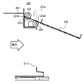
図12〜図16に、第2の実施形態の電気機器収納用箱の通風装置200(以下、通風装置200とする)を示して、第1の実施形態の通風装置100と異なる点について、通風装置200を説明する。図12〜図14は、通風装置200を、横向きの姿勢で、電気機器収納用箱99の天井面に取り付けた状態を表した図である。図12〜図14に示されるように、通風装置200は、筐体201、ファン10、シャッター202、重り203、ヒンジ204とから構成されている。筐体201は、前記した筐体101と同様の構造であり、その側方に開放する排気口201aが形成され、その内部にファン10が取り付けられている。
(Ventilation device for electric equipment storage box of second embodiment)
FIG. 12 to FIG. 16 show a ventilation device 200 (hereinafter, referred to as a ventilation device 200) for an electric device storage box according to the second embodiment, and the difference from the
図13に示されるように、排気口201aの上方位置の筐体201には、排気口201aを閉塞する板状のシャッター202がヒンジ204により回動可能に取り付けられている。図13に示されるように、シャッター202の回動軸202bからは、上方に延出する延出片202aが形成されている。図13に示されるように、延出片202aの先端の外側には、重り203が取り付けられている。図に示される重り203は板状であるが、ブロック状であっても差し支え無い。なお、シャッター202はアルミニウムや樹脂等の比重が軽い材質で構成されているが、重り203は鉄や鉛等、シャッター202に比べて比重が重い材料で構成されている。図13や図14に示されるように、排気口201aの上方の筐体201には、筐体201の内側に凹陥した形状の空間201aが形成され、シャッター202が回動可能となっている。なお、筐体201aの延出片202aと対向する部分は、規制壁201bとなっている。この規制壁201bの役割については、後述する。
As shown in FIG. 13, a plate-
以下に、図12〜図14を用いて、排気口201aを横側に向けた横向き姿勢で、通風装置200を電気機器収納用箱99の天井面に取り付けた場合の作用について説明する。
ファン10が停止している状態では、図12や図13に示されるように、シャッター202の自重により、排気口201aがシャッター202で閉塞される。この状態では、シャッター202に、重り203の重量も作用するので、排気口201aがシャッター202で確実に閉塞され、風によるシャッター202の開放が防止され、排気口201aからの異物の進入が防止される。
一方で、ファン10が稼働している状態では、図14に示されるように、ファン10で発生する風圧により、シャッター202が回動軸202bを中心に回動し、排気口201aが開放される。図14に示されるように、延出片202aの先端は規制壁201bと当接するので、シャッター202の所定角度以上の回動が規制される。これにより、シャッター202が開いたままの状態となってしまうことが防止される。
Hereinafter, the operation when the
When the
On the other hand, when the
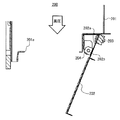
図15、図16は、排気口201aを下側に向けた縦向きの姿勢で、通風装置200を電気機器収納用箱99の側面に取り付けた状態を示した図である。以下に、図15、図16を用いて、縦向きの姿勢で、通風装置200を電気機器収納用箱99の側面に取り付けた場合の作用について説明する。
ファン10が停止している状態では、図15に示されるように、重り203の重量により、シャッター202が排気口201aを閉塞する方向に回動され、排気口201aがシャッター202で閉塞される。詳述すると、通風装置200が縦向きの姿勢では、延出片202a及び重り203の質量により生じる回動軸202b回りのモーメントのほうが、シャッター202の質量により生じる回動軸202b回りのモーメントよりも大きいので、シャッター202が排気口201aを閉塞した状態が維持される。
一方で、ファン10が稼働している状態では、図16に示されるように、ファン10で発生する風圧により、シャッター202が回動軸202bを中心に回動して、排気口201aが開放される。
このように、通風装置200は、横向き又は縦向きの両方の姿勢で、電気機器収納用箱99の天井面又は側面に取り付けて使用することが可能となっている。
FIGS. 15 and 16 are views showing a state in which the
In the state where the
On the other hand, when the
As described above, the
図13及び図15に示されるように、通風装置200は、横向き姿勢よりも縦向き姿勢のほうが、シャッター202の回動軸202bと重り203の重心との水平方向距離が大きくなるように構成されている。この構成による効果について説明する。
通風装置200を、横向きの姿勢で、電気機器収納用箱99の天井面に取り付けた状態では、図13に示されるように、重り203の重心と回動軸202bの水平方向距離Eは、短い。このため、ファン10稼働時において、重り203によりシャッター202が閉じる方向に作用するモーメントは小さく、シャッター202の開放の阻害となりにくい。
一方で、通風装置200を、縦向き姿勢で、電気機器収納用箱99の側面に取り付けた状態では、図15に示されるように、重り203の重心と回動軸202bとの水平方向距離Fは大きくなり、重り203によりシャッター202が閉じる方向に作用するモーメントは大きく、シャッター202が確実に排気口201aを閉塞する。
As shown in FIGS. 13 and 15, the
In a state where the
On the other hand, in the state where the
(第3の実施形態の電気機器収納用箱の通風装置)
図17〜図23に、第3の実施形態の電気機器収納用箱の通風装置300(以下、通風装置300とする)を示して、第1の実施形態の通風装置100と異なる点について、通風装置300を説明する。図17〜図20は、通風装置300を、横向きの姿勢で、電気機器収納用箱99の天井面に取り付けた状態を表した図である。図17〜図20に示されるように、通風装置300は、筐体301、ファン10、シャッター302、ヒンジ303、支持部材304、重り305、ワイヤー306とから構成されている。筐体301は前記した筐体101と同様の構造であり、その側方に開放する排気口301aが形成され、その内部にファン10が取り付けられている。
(Ventilation device for electrical equipment storage box of third embodiment)
FIGS. 17 to 23 show a ventilation device 300 (hereinafter, referred to as a ventilation device 300) for an electrical equipment storage box according to the third embodiment, and the difference from the
図18や図20に示されるように、排気口301aの上方位置の筐体301には、排気口301aを閉塞する板状のシャッター302がヒンジ303により回動可能に取り付けられている。図18に示されるように、本実施形態では、シャッター302は、その上端よりもやや下側の回動軸302aで、排気口301a上方の筐体301に軸着されている。
As shown in FIGS. 18 and 20, a plate-
図17〜図20に示されるように、筐体301の排気口301aの上方部分には、側方(排気側方向)に延出する支持部材304が取り付けられている。支持部材304は、水平方向に延出する支持板304aと、この支持板304aの両側端から上方に折曲形成された支持片304b、支持板304bの先端から折曲形成された支持片304cとから構成されている。支持板304b上には、重り305が移動可能に載置されている。図18に示されるように、重り305は、シャッター302の回動軸302aよりも上側の接続部302bと、ワイヤー306で接続されている。なお、シャッター302はアルミニウムや樹脂等の比重が軽い材質で構成されているが、重り305は鉄や鉛等、シャッター302に比べて比重が重い材料で構成されている。
As shown in FIGS. 17 to 20, a
以下に、図17〜図20を用いて、排気口301aを横側に向けた横向き姿勢で、通風装置300を電気機器収納用箱99の天井面に取り付けた場合の作用について説明する。
ファン10が停止している状態では、図17や図18に示されるように、シャッター302の自重により、排気口301aがシャッター302で閉塞される。
一方で、ファン10が稼働している状態では、図19や図20に示されるように、ファン10で発生する風圧により、シャッター302が回動軸302bを中心に回動し、排気口301aが開放される。なお、第3の実施形態の通風装置300を横向きの姿勢で取り付けた場合には、シャッター302が開放する際に、重り305の重量はシャッター302に作用しない。
Hereinafter, the operation when the
When the
On the other hand, when the
図21〜図23は、排気口301aを下側に向けた縦向きの姿勢で、通風装置300を電気機器収納用箱99の側面に取り付けた状態を示した図である。以下に、図21〜図23を用いて、縦向きの姿勢で、通風装置300を電気機器収納用箱99の側面に取り付けた場合の作用について説明する。
ファン10が停止している状態では、図22に示されるように、重り305の重量により、シャッター302が排気口301aを閉塞する方向に回動され、排気口301aがシャッター302で閉塞される。
一方で、ファン10が稼働している状態では、図23に示されるように、ファン10で発生する風圧により、シャッター302が回動軸302bを中心に回動して、排気口301aが開放される。
このように、通風装置300は、横向き又は縦向きの両方の姿勢で、電気機器収納用箱99の天井面又は側面に取り付けて使用することが可能となっている。
FIGS. 21 to 23 are views showing a state in which the
In the state where the
On the other hand, when the
As described above, the
(第4の実施形態の電気機器収納用箱の通風装置)
図24〜図29に、第4の実施形態の電気機器収納用箱の通風装置400(以下、通風装置400とする)を示して、第1の実施形態の通風装置100と異なる点について、通風装置400を説明する。図24〜図27は、通風装置400を、横向きの姿勢で、電気機器収納用箱99の天井面に取り付けた状態を表した図である。図24〜図27に示されるように、通風装置400は、筐体401、ファン10、シャッター402、重り403とから構成されている。筐体401は前記した筐体101と同様の構造であり、その側方に開放する排気口401aが形成され、その内部にファン10が取り付けられている。
(Ventilation device for electric device storage box of fourth embodiment)
FIGS. 24 to 29 show a ventilation device 400 (hereinafter referred to as a ventilation device 400) for an electric equipment storage box according to the fourth embodiment, and the difference from the
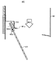
図25に示されるように、排気口401aの下方位置の筐体401には、排気口401aを閉塞する板状のシャッター402が回動可能に取り付けられている。本実施形態では、シャッター402は、その下端よりもやや上側の回動軸402aで、筐体401に軸着されている。シャッター402は、その下側が筐体401の内部側を向き、その上端側が筐体401の外側を向くように傾斜している。なお、シャッター402が排気口401aを閉塞している状態でのシャッター402の傾斜角は、鉛直方向から45°以下の角度である。シャッター402の回動軸402aからは、下方に延出する延出片402bが形成されている。延出片402bの先端には、板状又はブロック状の重り403が取り付けられている。なお、シャッター402はアルミニウムや樹脂等の比重が軽い材質で構成されているが、重り403は鉄や鉛等、シャッター402に比べて比重が重い材料で構成されている。
As shown in FIG. 25, a plate-
以下に、図24〜図27を用いて、排気口401aを横側に向けた横向き姿勢で、通風装置400を電気機器収納用箱99の天井面に取り付けた場合の作用について説明する。
ファン10が停止している状態では、図24や図25に示されるように、重り403の重量がシャッター402に作用して、シャッター402が排気口401aを閉塞する方向に回動され、排気口401aがシャッター402で閉塞される。詳述すると、通風装置400が縦向きの姿勢では、延出片402b及び重り403の質量により生じる回動軸402a回りのモーメントのほうが、シャッター402の質量により生じる回動軸402a回りのモーメントよりも大きいので、シャッター402が排気口401aを閉塞した状態が維持される。
一方で、ファン10が稼働している状態では、図27に示されるように、ファン10で発生する風圧により、シャッター402が回動軸402aを中心に回動し、排気口401aが開放される。
Hereinafter, the operation when the
In the state where the
On the other hand, when the
図28、図29は、排気口401aを下側に向けた縦向きの姿勢で、通風装置400を電気機器収納用箱99の側面に取り付けた状態を示した図である。以下に、図28、図29を用いて、縦向きの姿勢で、通風装置400を電気機器収納用箱99の側面に取り付けた場合の作用について説明する。
ファン10が停止している状態では、図28に示されるように、重り403の重量により、シャッター402が排気口401aを閉塞する方向に回動され、排気口401aがシャッター402で閉塞される。
一方で、ファン10が稼働している状態では、図29に示されるように、ファン10で発生する風圧により、シャッター402が回動軸402aを中心に回動して、排気口401aが開放される。
28 and 29 are views showing a state in which the
In the state where the
On the other hand, when the
通風装置400を、横向きの姿勢で、電気機器収納用箱99の天井面に取り付けた状態では、図25に示されるように、重り403の重心と回動軸402aの水平方向距離G、は小さい。このため、ファン10稼働時において、重り403によりシャッター402が閉じる方向に作用するモーメントは小さく、シャッター402の開放の阻害となりにくい。
一方で、通風装置400を、縦向き姿勢で、電気機器収納用箱99の側面に取り付けた状態では、図27に示されるように、重り403の重心と回動軸402aの水平方向距離Hは大きくなり、重り403によりシャッター402が閉じる方向に作用するモーメントは大きく、シャッター402が排気口401aを確実に閉塞する。
このように、通風装置400は、横向き又は縦向きの両方の姿勢で、電気機器収納用箱99の天井面又は側面に取り付けて使用することが可能となっている。
In a state where the
On the other hand, in the state where the
Thus, the
(カバーを取り付けた実施形態の説明)
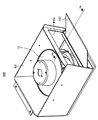
図30、図31を用いて、本発明の通風装置100〜400に、防水カバー99を取り付けた実施形態の説明をする。
図30、図31に示されるように、防水カバー99は、側方に排気口99aが、底部に取付口99bが形成された箱形である。排気口99aには、多数のスリット穴が形成された異物侵入防止部材99eが取り付けられている。図31に示されるように、異物侵入防止部材99eの内側には、不織紙や不織布等で構成されフィルタ99fが取り付けられている。
(Description of embodiment with cover attached)
An embodiment in which a
As shown in FIGS. 30 and 31, the
防水カバー99を通風装置100〜400に取り付けるには、取付口99bから通風装置100〜400を防水カバー99内に挿通させて、ネジ97により通風装置100〜400に取り付ける。防水カバー99は、ネジ97により通風装置100〜400に取り付けられているので、着脱可能となっている。なお、図30の(B)や図31に示されるように、防水カバー99の排気口99a側の底部には、防水カバー99の排気口99a下端から、筐体101の排気口101aの下端まで延出する、防水板99dが形成されている。防水カバー99が取り付けられた状態では、通風装置100〜400は、防水カバー99で覆われている。このため、通風装置100〜400や電気機器収納用箱99内への雨水の進入をより確実に防止することが可能となる。防水カバー99は通風装置100〜400と一体でなく着脱可能な構造となっているので、防水カバー99を通風装置100〜400に取り付ける前に、電気機器収納用箱99と通風装置100〜400との取付面に、コーキング剤を塗布することができ、より防水性を高めることができる。
In order to attach the
なお、防止カバー99を通風装置100〜400取り付ける実施形態の場合には、筐体101〜401の天井面は不要であり、筐体101〜401は上方に開放した構造となっている。なお、防水性を確保するために、筐体101〜401の上端周縁と防水カバー99の天井面99cとの間に、パッキンを取り付けることが好ましい。筐体101〜401は上方に開放した構造となっているので、防水カバー99を取り外して、ファン10を交換することができる。また、防水カバー99は通風装置100〜400と一体でなく着脱可能な構造となっているので、フィルタ99fを交換することができる。
In the case of the embodiment in which the ventilating
図31に示されるように、防水カバー99の天井面99cや防水板99dは、排気口99a側が低くなるように、傾斜している。このため、天井面99cや防水板99d上の雨水が溜まること無く排気口99a側に流れ落ちるようになっている。
As shown in FIG. 31, the
以上、現時点において、もっとも、実践的であり、かつ好ましいと思われる実施形態に関連して本発明を説明したが、本発明は、本願明細書中に開示された実施形態に限定されるものではなく、請求の範囲および明細書全体から読み取れる発明の要旨あるいは思想に反しない範囲で適宜変更可能であり、そのような変更を伴う電気機器収納用箱の通風装置もまた技術的範囲に包含されるものとして理解されなければならない。 Although the present invention has been described above in connection with the most practical and preferred embodiments at the present time, the present invention is not limited to the embodiments disclosed herein. The present invention can be changed as appropriate without departing from the spirit or concept of the invention that can be read from the claims and the entire specification, and a ventilation device for an electric equipment storage box with such a change is also included in the technical scope. It must be understood as a thing.
10 ファン
99 防水カバー
100 第1の実施形態の電気機器収納用箱の通風装置
101 筐体
101a 排気口
101b 吸入口
101c 天井面
102 シャッター
102a 第1回動軸
102b 第2回動軸
102c 延出片
103 重り
104 ヒンジ
105 ヒンジ
106 移動規制部材
107 重り
200 第2の実施形態の電気機器収納用箱の通風装置
201 筐体
202 シャッター
202a 延出片
202b 回動軸
300 第3の実施形態の電気機器収納用箱の通風装置
301 筐体
302 シャッター
302a 回動軸
302b 接続部
303 ヒンジ
304 支持部材
305 重り
306 ワイヤー
400 第4の実施形態の電気機器収納用箱の通風装置
401 筐体
402 シャッター
402a 回動軸
402b 延出片
403 重り
DESCRIPTION OF
Claims (5)
底面に吸入口が形成されるとともに、側方に開放する排気口が形成された箱形の筐体と、
前記筐体内に取り付けられ、前記吸入口からの吸気を前記排気口から排気させるファンと、
前記排気口を閉塞するように、前記筐体に回動可能に取り付けられた板状のシャッターと、
前記シャッターの回動軸から前記シャッターと反対側方向に延出する延出片と、
前記延出片に取り付けられた重りを有し、
前記側面に形成された排気穴と前記吸入口を連通させ、前記排気口を下側に向けた縦向きの姿勢で前記側面に取り付けた場合には、前記延出片及び前記重りの質量により生じる前記回動軸回りのモーメントのほうが、前記シャッターの質量により生じる前記回動軸回りのモーメントよりも大きく構成されていることを特徴とする電気機器収納用箱の通風装置。 A ventilation device that can be attached to either a ceiling surface or a side surface of an electrical equipment storage box and exhausts air inside the box to the outside from an exhaust hole formed in the ceiling surface or the side surface,
A box-shaped housing having a suction port formed on the bottom surface and an exhaust port opening to the side;
A fan attached to the housing and exhausting the intake air from the intake port through the exhaust port;
A plate-like shutter rotatably attached to the housing so as to close the exhaust port;
An extending piece extending in a direction opposite to the shutter from the rotation axis of the shutter;
Having a weight attached to the extension piece;
When the exhaust hole formed in the side surface communicates with the suction port, and the exhaust port is attached to the side surface in a vertically oriented posture facing downward, it is generated by the mass of the extension piece and the weight. A ventilation device for an electric equipment storage box, wherein a moment around the rotation axis is configured to be larger than a moment around the rotation axis caused by the mass of the shutter.
前記延出片は、前記シャッターの回動軸から上方に延出し、
前記重りは前記延出片の外側に取り付けられていることを特徴とする請求項1又は請求項2に記載の電気機器収納用箱の通風装置。 The shutter is rotatably attached to a housing above the exhaust port,
The extension piece extends upward from the rotation axis of the shutter,
The ventilator for an electric equipment storage box according to claim 1 or 2, wherein the weight is attached to the outside of the extension piece.
前記延出片は、前記シャッターの回動軸から下方に延出していることを特徴とする請求項1又は請求項2に記載の電気機器収納用箱の通風装置。 The shutter is rotatably attached to a housing below the exhaust port,
The ventilating device for an electric equipment storage box according to claim 1, wherein the extending piece extends downward from a rotation shaft of the shutter.
Priority Applications (1)
| Application Number | Priority Date | Filing Date | Title |
|---|---|---|---|
| JP2011040129A JP2012177501A (en) | 2011-02-25 | 2011-02-25 | Ventilation device of box for storing electrical equipment |
Applications Claiming Priority (1)
| Application Number | Priority Date | Filing Date | Title |
|---|---|---|---|
| JP2011040129A JP2012177501A (en) | 2011-02-25 | 2011-02-25 | Ventilation device of box for storing electrical equipment |
Publications (1)
| Publication Number | Publication Date |
|---|---|
| JP2012177501A true JP2012177501A (en) | 2012-09-13 |
Family
ID=46979451
Family Applications (1)
| Application Number | Title | Priority Date | Filing Date |
|---|---|---|---|
| JP2011040129A Pending JP2012177501A (en) | 2011-02-25 | 2011-02-25 | Ventilation device of box for storing electrical equipment |
Country Status (1)
| Country | Link |
|---|---|
| JP (1) | JP2012177501A (en) |
Cited By (3)
| Publication number | Priority date | Publication date | Assignee | Title |
|---|---|---|---|---|
| JP2016157729A (en) * | 2015-02-23 | 2016-09-01 | 富士通株式会社 | Electronic apparatus unit and electronic device |
| CN111479423A (en) * | 2020-05-09 | 2020-07-31 | 余正电子科技(嘉兴)有限公司 | Electric circuit controller with overheat protection function |
| WO2023067804A1 (en) * | 2021-10-22 | 2023-04-27 | 東芝三菱電機産業システム株式会社 | Wind pressure shutter for outddor distribution board |
Citations (4)
| Publication number | Priority date | Publication date | Assignee | Title |
|---|---|---|---|---|
| JPS5463237A (en) * | 1977-10-27 | 1979-05-22 | Mitsubishi Electric Corp | Forced draft device of swichboard |
| JPS641344U (en) * | 1987-06-22 | 1989-01-06 | ||
| US5277658A (en) * | 1992-12-21 | 1994-01-11 | Goettl George M | Barometric damper apparatus |
| FR2782054A1 (en) * | 1998-08-10 | 2000-02-11 | Rehau Sa | Vehicle equipped with air damper with counterweight |
-
2011
- 2011-02-25 JP JP2011040129A patent/JP2012177501A/en active Pending
Patent Citations (4)
| Publication number | Priority date | Publication date | Assignee | Title |
|---|---|---|---|---|
| JPS5463237A (en) * | 1977-10-27 | 1979-05-22 | Mitsubishi Electric Corp | Forced draft device of swichboard |
| JPS641344U (en) * | 1987-06-22 | 1989-01-06 | ||
| US5277658A (en) * | 1992-12-21 | 1994-01-11 | Goettl George M | Barometric damper apparatus |
| FR2782054A1 (en) * | 1998-08-10 | 2000-02-11 | Rehau Sa | Vehicle equipped with air damper with counterweight |
Cited By (4)
| Publication number | Priority date | Publication date | Assignee | Title |
|---|---|---|---|---|
| JP2016157729A (en) * | 2015-02-23 | 2016-09-01 | 富士通株式会社 | Electronic apparatus unit and electronic device |
| CN111479423A (en) * | 2020-05-09 | 2020-07-31 | 余正电子科技(嘉兴)有限公司 | Electric circuit controller with overheat protection function |
| WO2023067804A1 (en) * | 2021-10-22 | 2023-04-27 | 東芝三菱電機産業システム株式会社 | Wind pressure shutter for outddor distribution board |
| JP7392900B2 (en) | 2021-10-22 | 2023-12-06 | 東芝三菱電機産業システム株式会社 | Wind pressure shutter for outdoor switchboard |
Similar Documents
| Publication | Publication Date | Title |
|---|---|---|
| JP5196166B2 (en) | Air conditioner outdoor unit | |
| WO2005098319A1 (en) | Indoor unit of air conditioner | |
| JP4987123B2 (en) | Ventilation equipment | |
| JP2012177501A (en) | Ventilation device of box for storing electrical equipment | |
| JP6479183B2 (en) | Indoor unit and air conditioner | |
| JP5053244B2 (en) | Ventilation equipment | |
| JP6479219B2 (en) | Ventilation fan | |
| JP2017009249A (en) | Ventilating fan | |
| JP5455949B2 (en) | Ventilation fan | |
| KR100970054B1 (en) | Apparatus for opening and closing flow path, and air conditioner | |
| KR100907755B1 (en) | Ventilator | |
| JP5602090B2 (en) | Ventilation fan for duct | |
| KR101852920B1 (en) | Supply air or Exhaust air type Slim Fan with flap divece system | |
| JP6053540B2 (en) | Ventilation equipment | |
| JP5484269B2 (en) | Ventilation fan | |
| JP2020180730A (en) | Duct air blowing device | |
| JP2010139135A (en) | Ventilation fan | |
| JP6973272B2 (en) | Ventilation fan and makeup grill | |
| JP4805041B2 (en) | Ventilation fan | |
| JP7442681B2 (en) | Shutter device and ventilation device | |
| WO2023067804A1 (en) | Wind pressure shutter for outddor distribution board | |
| JP5454550B2 (en) | Ventilation equipment | |
| WO2021157070A1 (en) | Blower and ventilation device | |
| JP6026170B2 (en) | Door with ventilation function | |
| JP2023139948A (en) | Ventilation fan and attachment member |
Legal Events
| Date | Code | Title | Description |
|---|---|---|---|
| A621 | Written request for application examination |
Free format text: JAPANESE INTERMEDIATE CODE: A621 Effective date: 20140107 |
|
| A977 | Report on retrieval |
Free format text: JAPANESE INTERMEDIATE CODE: A971007 Effective date: 20140620 |
|
| A131 | Notification of reasons for refusal |
Free format text: JAPANESE INTERMEDIATE CODE: A131 Effective date: 20140627 |
|
| A521 | Written amendment |
Free format text: JAPANESE INTERMEDIATE CODE: A523 Effective date: 20140822 |
|
| A02 | Decision of refusal |
Free format text: JAPANESE INTERMEDIATE CODE: A02 Effective date: 20150224 |