WO2023065482A1 - 注塑方法 - Google Patents
注塑方法 Download PDFInfo
- Publication number
- WO2023065482A1 WO2023065482A1 PCT/CN2021/136620 CN2021136620W WO2023065482A1 WO 2023065482 A1 WO2023065482 A1 WO 2023065482A1 CN 2021136620 W CN2021136620 W CN 2021136620W WO 2023065482 A1 WO2023065482 A1 WO 2023065482A1
- Authority
- WO
- WIPO (PCT)
- Prior art keywords
- cavity
- injection molding
- insert
- bearing surface
- sleeve
- Prior art date
- Legal status (The legal status is an assumption and is not a legal conclusion. Google has not performed a legal analysis and makes no representation as to the accuracy of the status listed.)
- Ceased
Links
Images


Classifications
-
- B—PERFORMING OPERATIONS; TRANSPORTING
- B29—WORKING OF PLASTICS; WORKING OF SUBSTANCES IN A PLASTIC STATE IN GENERAL
- B29C—SHAPING OR JOINING OF PLASTICS; SHAPING OF MATERIAL IN A PLASTIC STATE, NOT OTHERWISE PROVIDED FOR; AFTER-TREATMENT OF THE SHAPED PRODUCTS, e.g. REPAIRING
- B29C45/00—Injection moulding, i.e. forcing the required volume of moulding material through a nozzle into a closed mould; Apparatus therefor
- B29C45/14—Injection moulding, i.e. forcing the required volume of moulding material through a nozzle into a closed mould; Apparatus therefor incorporating preformed parts or layers, e.g. injection moulding around inserts or for coating articles
- B29C45/14065—Positioning or centering articles in the mould
-
- B—PERFORMING OPERATIONS; TRANSPORTING
- B29—WORKING OF PLASTICS; WORKING OF SUBSTANCES IN A PLASTIC STATE IN GENERAL
- B29C—SHAPING OR JOINING OF PLASTICS; SHAPING OF MATERIAL IN A PLASTIC STATE, NOT OTHERWISE PROVIDED FOR; AFTER-TREATMENT OF THE SHAPED PRODUCTS, e.g. REPAIRING
- B29C45/00—Injection moulding, i.e. forcing the required volume of moulding material through a nozzle into a closed mould; Apparatus therefor
- B29C45/17—Component parts, details or accessories; Auxiliary operations
- B29C45/26—Moulds
-
- B—PERFORMING OPERATIONS; TRANSPORTING
- B29—WORKING OF PLASTICS; WORKING OF SUBSTANCES IN A PLASTIC STATE IN GENERAL
- B29C—SHAPING OR JOINING OF PLASTICS; SHAPING OF MATERIAL IN A PLASTIC STATE, NOT OTHERWISE PROVIDED FOR; AFTER-TREATMENT OF THE SHAPED PRODUCTS, e.g. REPAIRING
- B29C45/00—Injection moulding, i.e. forcing the required volume of moulding material through a nozzle into a closed mould; Apparatus therefor
- B29C45/14—Injection moulding, i.e. forcing the required volume of moulding material through a nozzle into a closed mould; Apparatus therefor incorporating preformed parts or layers, e.g. injection moulding around inserts or for coating articles
- B29C45/14065—Positioning or centering articles in the mould
- B29C2045/14155—Positioning or centering articles in the mould using vacuum or suction
Definitions
- Embodiments of the present disclosure relate to the technical field of injection molding, and more specifically, to an injection molding method.
- Injection molding When the shell of the product is provided with an embedded structure, it is usually injection molded after inserting the insert in the mold. It is usually necessary to fasten the Insert to the moving mold. However, the inserts of the mold are easy to drop during the mold clamping process.
- An object of the present disclosure is to provide a new technical solution of the injection molding method.
- an injection molding method comprises:
- a fixing device an insert and a mold, wherein a cavity is provided inside the mold, the fixing device is located in the cavity, the fixing device has a bearing surface, and the bearing surface is used to bear the An insert, an air hole is formed in the fixing device, the air hole has a first opening and a second opening, the first opening is located on the bearing surface, and the second opening is used for contacting with the negative
- the pressure device is connected, and one end surface of the insert is opposite to the first mouth;
- the injection molded product is separated from the cavity and the insert is separated from the bearing surface.
- the fixing device includes a sleeve and a thimble, a cavity is formed in the middle of the sleeve, the thimble is located in the cavity, and an end surface of the sleeve surrounding the thimble forms a
- the bearing surface, the sleeve is formed with the air hole, and after the injection molding is completed, the thimble protrudes along the axial direction of the sleeve, so as to separate the injection molded product from the cavity and separate the molded product.
- the insert is separated from the bearing surface.
- the insert is a nut, and the nut has a screw hole, and the thimble extends into the screw hole.
- the sleeve has a side surface connected to the bearing surface, a communication cavity is provided in the sleeve, the second mouths of the plurality of air holes communicate with the communication cavity, and A third port is formed on the side surface, and the third port communicates with the communication cavity.
- the communication cavity is formed by electric spark discharge.
- the communication cavity is arranged around the thimble.
- the communication cavity communicates with the cavity.
- an axially extending groove is formed on one side of the fixing device close to the cavity, and the outer wall of the thimble and the groove jointly enclose the air hole.
- the inner diameter of the pores is 0.8mm-1.5mm.
- Air holes are provided on the fixing device, and a negative pressure is formed in the air holes, so that the first mouth can form an adsorption force on the insert along the axial direction of the fixing device to adsorb the insert on the bearing surface. In this way, it is possible to avoid loosening or falling of the insert during the injection molding process.
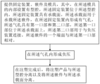
- Fig. 1 is the flowchart of an embodiment of the injection molding method of the present disclosure
- Fig. 2 is the flowchart of an embodiment of the injection molding method of the present disclosure
- Fig. 3 is a structural schematic diagram of an embodiment of the fixing device of the present disclosure
- Fig. 4 (a) is one of the top views of Fig. 3;
- Fig. 4 (b) is the second top view of Fig. 3;
- Fig. 5 is a partial structural schematic diagram of an embodiment of the mold of the present disclosure.
- Fig. 6 is a partially enlarged view of part A in Fig. 5;
- FIG. 7 is a schematic diagram of the formation of the communication cavity in the embodiment of the present disclosure.
- connection should be understood in a broad sense, for example, it can be a fixed connection, a detachable connection, or an integral connection; it can be A mechanical connection can also be an electrical connection; it can be a direct connection or an indirect connection through an intermediary, and it can be the internal communication of two components.
- a mechanical connection can also be an electrical connection; it can be a direct connection or an indirect connection through an intermediary, and it can be the internal communication of two components.
- an injection molding method includes providing a fixture 10 , an insert and a mold 20 .
- a cavity is provided inside the mold 20 .
- the fixture 10 is located within the cavity.
- the fastening device 10 has a support surface 16 .
- the carrying surface 16 serves to carry the insert.
- An air hole 14 is formed in the fixing device 10 .
- the air hole 14 has a first mouth 15 and a second mouth.
- the first mouth 15 is located on the bearing surface 16 .
- the second port is used to connect with the negative pressure device.
- One end face of the insert is opposite the first mouth 15 .
- a negative pressure is created in the air holes 14 .
- the injection molded product is separated from the cavity and the insert is separated from the bearing surface 16 .
- the carrying surface 16 serves to carry the insert.
- the insert can be a nut 17, a bushing or a bushing.
- the first mouth portion 15 forms a negative pressure on the bearing surface 16 .
- the insert placed on the bearing surface 16 can be adsorbed on the bearing surface 16 to avoid loosening or falling of the insert during the injection molding process.
- the insert can be more easily separated from the fixing device 10 after injection moulding. In this way, it is possible to avoid acting on the rubber lagging around the insert of the injection molded product, and to avoid the technical problem of poor rubber lagging.
- the cavity is an integral cavity or a split cavity.
- Integral mold cavity that is, a concave mold cavity in which the mold cavity is surrounded by a whole mold 20 .
- the mold cavity is a combined mold cavity, for example, the mold 20 includes multiple parts, and the multiple parts are spliced to form a combined mold cavity.
- the fixing device 10 is a device capable of setting and holding the insert at a predetermined position in the cavity.
- Negative pressure is formed in the air hole 14, and then injection plastic is injected into the cavity. In this way, it is possible to avoid loosening or falling of the insert when the cavity is displaced.
- a negative pressure can be formed in the air hole 14 while injecting the injection material.
- the injection molded part After negative pressure is formed in the air hole 14 , the injection molded part is adsorbed on the bearing surface 16 .
- the projection range of the injection molded part covers the projection range of the first air hole 14 . In this way, when the insert is wrapped with plastic to form the rubber covering part, the stress of the rubber covering part on the insert is avoided, which may lead to misalignment of the insert.
- the injection molded product is separated from the cavity, and the insert is separated from the bearing surface 16 . It may be that when the insert is separated from the bearing surface 16, the air hole 14 still maintains a negative pressure state.
- FIG. 4( a ) or FIG. 4( b ) there are multiple air holes 14 .
- a plurality of first openings 15 are formed on the carrying surface 16 . In this way, the insert is more firmly adsorbed on the surface of the bearing surface 16 .
- the fixing device 10 includes a sleeve 11 and a thimble 12 , and a cavity is formed in the middle of the sleeve 11 .
- the thimble 12 is located in the cavity, and an end surface of the sleeve 11 surrounding the thimble 12 forms a bearing surface 16 .
- the sleeve 11 is formed with air holes 14 . After the injection molding is completed, the thimble 12 protrudes along the axial direction of the sleeve 11 to separate the injection molded product from the cavity and the insert from the bearing surface 16 .
- the ejector pin 12 can move up and down in the cavity of the sleeve 11 along the axial direction of the sleeve 11 to push the injection molded product out of the injection molding material.
- the fixing device 10 only includes a fixing base, and the fixing base has a bearing surface 16 for bearing the insert.
- An air hole 14 is formed on the side wall of the fixing seat, and the air hole 14 includes a first opening 15 and a second opening 16 .
- the first mouth 15 is located on the bearing surface 16 , and the second mouth is connected with a negative pressure device to form a negative pressure in the air hole 14 , so that the insert is adsorbed on the bearing surface 16 .
- the thimble 12 can be used to separate the insert from the fixing device 10 after the injection molding is completed.
- the steps of separating the injection molded product from the cavity and separating the insert from the bearing surface 16 include:
- the thimble 12 protrudes along the axial direction of the sleeve 11 to separate the injection molded product from the cavity and the insert from the bearing surface 16 .
- a part of the thimble 12 can stretch out from the cavity to protrude from the bearing surface 16. That is, the end surface of the thimble 12 in contact with the injection molded product can protrude outward to protrude from the bearing surface 16 , and can also be retracted into the cavity.
- the ejector pin 12 When separating the insert from the bearing surface 16 , the ejector pin 12 protrudes from the cavity and protrudes from the bearing surface 16 until it contacts the surface of the injection molded product. Continue to apply force to the thimble 12, so that the thimble 12 continues to protrude outward. Until the bearing surface 16 is separated from the insert inserted into the injection molded product.
- the insert can be easily separated from the fixing device 10, avoiding stress on the lagging around the insert in the injection molded product to avoid damage or poor lagging of the insert in the injection molded product The problem.
- a plurality of first mouth portions 15 are evenly distributed along the sleeve 11 around the thimble 12 .
- the negative pressure on the end surface of the insert in contact with the bearing surface 16 is more balanced.
- the four air holes 14 form four first openings 15 on the bearing surface 16 .
- the four first mouths 15 are evenly distributed around the thimble 12 .
- the six air holes 14 there are six air holes 14 , and the six air holes 14 form six first openings 15 on the bearing surface 16 .
- Six first mouths 15 are distributed circularly around the cavity. In this way, the fixing effect on the insert is further improved.
- the number of air holes 14 is not limited to the above embodiments, and those skilled in the art can set them according to actual needs.
- the air hole 14 may communicate with the cavity or be arranged at a distance from the cavity.
- the air hole 14 may be located in the side wall of the sleeve 11, the air hole 14 is located between the inner wall and the outer wall of the sleeve 11, and is separated from the cavity.
- the method for forming air hole 14 is:
- a sleeve 11 is prepared, and a cavity is formed in the middle of the sleeve 11 .
- a hole is drilled downwards along the axial direction of the sleeve 11, and a hole parallel to the central axis of the cavity is formed at a position between the inner wall and the outer wall of the sleeve 11.
- the first through hole 13 is a part of the air hole 14 .
- a second hole perpendicular to the central axis of the first through hole 13 is formed.
- the through hole is to communicate with the first through hole 13 and the second through hole, and the second through hole is another part of the air hole 14.
- the air hole 14 is formed, and the second through hole is in the sleeve A second mouth is formed on the outer wall of 11.
- pores 14 can also be formed by other methods, such as grinding, cutting, or extrusion.
- Air holes 14 may also be provided on the inner wall of the sleeve 11 and communicate with the cavity.
- an axially extending groove is formed on the side of the sleeve 11 close to the cavity.
- the outer surface of the thimble 12 and the groove together form an air hole 14 .
- the groove can be formed by cutting.
- the cutting knife enters the cavity from one end of the cavity, and the cutting edge contacts the side wall of the cavity and forms a groove at a set position of the side wall of the cavity.
- the groove runs through the inner wall of the sleeve 11 in the axial direction and is parallel to the central axis of the cavity.
- the thimble 12 is placed in the cavity, so that the outer surface of the thimble 12 and the inner wall of the sleeve 11 together form an air hole 14 .
- the first mouth 15 is located on the carrying surface 16 , and the cross-sectional shape of the first mouth 15 is a circle, a rectangle, or the like. No specific limitation is imposed on the cross-sectional shape of the first mouth portion 15 here.
- the second port is used to connect with the negative pressure device. Turn on the negative pressure device to form a negative pressure in the air hole 14 so that the first mouth 15 can adsorb the insert on the bearing surface 16 .
- the second mouth is connected to the negative pressure device, and may also be connected to the negative pressure device through other structures.
- the inner diameter of the air hole 14 is 0.8mm-1.5mm. Within this range, the structure of the sleeve 11 is more stable while the air hole 14 satisfies the adsorption force on the insert.
- the insert is a nut 17 , the surface of one end of the nut 17 is opposite to the first mouth 15 , and the thimble 12 is located in the screw hole of the nut 17 .
- the thimble 12 is located in the screw hole, on the one hand, it plays a role of occupying space, and prevents the thread structure of the inner wall of the nut 17 and the through hole inside the nut 17 from being filled with injection molding material.
- the nut 17 can also be further fixed to prevent the nut 17 from being displaced when the orientation of the cavity changes.
- the sleeve 11 has a side surface connected to the bearing surface 16 .
- a communication cavity 18 is provided in the sleeve 11 .
- the second mouths of the plurality of air holes 14 communicate with the communication cavity 18 .
- a third mouth portion 19 is formed on the side surface. The third port 19 communicates with the communication cavity 18 .
- a plurality of air holes 14 are arranged parallel to each other and parallel to the central axis of the cavity.
- the second mouth is located in the side wall and isolated from the outside.
- a plurality of second mouths are all communicated with the communication chamber 18, and a third mouth 19 is formed on the side surface of the sleeve 11, the third mouth 19 is communicated with the communication chamber 18, and the third mouth 19 is connected with the negative pressure device to Negative pressure is realized in the communication chamber 18 to form a negative pressure in the air hole 14 through the second opening to adsorb the insert on the bearing surface 16 .
- the number of the third mouth 19 may be one or more. That is, when there is one communicating chamber 18, one third mouth 19 can be formed on the outer wall to communicate with the communicating chamber 18, or a plurality of third mouths 19 can be formed on the outer wall, and the plurality of third mouths 19 are all connected to the communicating chamber. 18 connected.
- third openings 19 when there are multiple third openings 19 , they may be evenly distributed around the side wall of the sleeve 11 .
- they when there are multiple third ports 19, they can be connected to multiple negative pressure devices.
- the communication cavity 18 is arranged perpendicular to the central axis of the air hole 14 .
- the communication chamber 18 communicates with the cavity.
- the communication cavity 18 is located on the inner wall of the sleeve 11 , and the outer wall of the thimble 12 and the inner wall of the sleeve 11 together form the communication cavity 18 .
- the communication cavity 18 is formed by electric spark discharge.
- the formation method of the communication chamber 18 is as follows:
- a steel needle 22 is provided, an electrode 23 matching the set shape of the communication cavity 18 is provided, and the steel needle 22 is connected with the electrode 23 to form an electrode assembly.
- the electrode assembly is connected with a spark machine, and the spark machine applies a set voltage to the electrode assembly to form a communication cavity 18 communicating with the air hole 14 .
- the diameter of the electrode assembly is smaller than the diameter of the cavity.
- the diameter of the cavity is 1mm, and the diameter of the electrode assembly can be between 0.1mm-0.5mm.
- the diameter of the electrode assembly is 0.4mm.
- the communication cavity 18 can be processed on the cavity wall of the cavity.
- the electrodes are cylindrical or arcuate.
- the electrodes are copper or copper alloy.
- the cross section of the electrode is circular, quadrangular, etc.
- the communication cavity 18 is disposed around the thimble 12 .
- the communication cavity 18 surrounds the thimble 12 and is along the side wall of the sleeve 11 .
- the cross-sectional shape of the communication cavity 18 is arc or ring.
- the plurality of communication cavities 18 are correspondingly connected to the set second ports.
- a third port 19 is formed on the outer wall of the sleeve 11 to communicate with the corresponding communication cavity 18 .
- the set third ports 19 can be respectively connected to the negative pressure device to form negative pressure in the set first port 15 .
- the mold 20 includes a movable mold part 21 and a static mold part. Referring to FIG. 5 and FIG. 6 , one end of the fixing device 10 is fixed on the movable mold part 21 .
- the nut 17 is sheathed on the thimble 12 and is located at the end of the fixing device 10 opposite to the movable mold part 21 .
- Negative pressure is formed in the air hole 14 so that the first mouth portion 15 can be fixed on the bearing surface 16 such as a nut 17 . Then the movable mold part 21 is moved and clamped with the static mold part to form a mold cavity.
- the fixing device 10 is separated from the nut 17 .
Landscapes
- Engineering & Computer Science (AREA)
- Manufacturing & Machinery (AREA)
- Mechanical Engineering (AREA)
- Moulds For Moulding Plastics Or The Like (AREA)
- Injection Moulding Of Plastics Or The Like (AREA)
Abstract
一种注塑方法,包括:提供固定装置(10)、嵌件及模具(20),其中,在所述模具(20)的内部设置有型腔,所述固定装置(10)位于所述型腔内,所述固定装置(10)具有承载面(16),所述承载面(16)用于承载所述嵌件,在所述固定装置(10)内形成有气孔(14),所述气孔(14)具有第一口部(15)和第二口部,所述第一口部(15)位于所述承载面(16)上,所述第二口部用于与负压装置连接,所述嵌件的一个端面与所述第一口部(15)相对;在所述气孔(14)内形成负压;向所述型腔内注入注塑料;在注塑完成后,将注塑产品与所述型腔分离以及将所述嵌件与所述承载面(16)分离。通过使第一口部(15)能对嵌件形成沿固定装置(10)的轴向的吸附力以将嵌件吸附在承载面(16),能够避免在注塑过程中,嵌件发生松动或掉落。
Description
本公开实施例涉及注塑技术领域,更具体地,涉及一种注塑方法。
注塑成型在产品的外壳设置嵌入结构时,通常在模具内嵌入嵌件后注塑成型。通常需要将嵌件固定在动模上。但是模具在合模过程中嵌件容易掉落。
在现有技术中,以螺母嵌件为例,为了防止螺母在模具合模过程中螺母松动或是掉落。使用与所述螺母相匹配的螺牙针,通过将螺牙针与螺母拧紧后,再将螺牙针及螺母整体嵌入模具内注塑。待完成注塑后,连同螺牙针一起顶出,再从产品上将螺牙针反向旋转,将螺牙针自螺母中取下,从而得到带有螺母的塑胶产品。
但是,这种方式效率低,工序复杂,且在注塑成型后,需要将螺牙针反向旋转以与螺母分离,容易导致螺母周边的包胶受到应力的作用,从而导致螺母包胶不良。
因此,需要提供一种新的技术方案,以解决上述技术问题。
发明内容
本公开的一个目的是提供一种注塑方法的新技术方案。
在本公开的一个实施例中,提供了一种注塑方法。所述注塑方法包括:
提供固定装置、嵌件及模具,其中,在所述模具的内部设置有型腔,所述固定装置位于所述型腔内,所述固定装置具有承载面,所述承载面用于承载所述嵌件,在所述固定装置内形成有气孔,所述气孔具有第一口部和第二口部,所述第一口部位于所述承载面上,所述第二口部用于与负压装置连接,所述嵌件的一个端面与所述第一口部相对;
在所述气孔内形成负压;向所述型腔内注入注塑料;
在注塑完成后,将注塑产品与所述型腔分离以及将所述嵌件与所述承载面分离。
可选地,所述气孔为多个,在所述承载面上形成有多个所述第一口部。
可选地,所述固定装置包括套筒和顶针,在所述套筒的中部形成有空腔,所述顶针位于所述空腔内,围绕着所述顶针的所述套筒的一个端面构成所述承载面,所述套筒形成有所述气孔,在注塑完成后,所述顶针沿所述套筒的轴向伸出,以将所述注塑产品与所述型腔分离以及将所述嵌件与所述承载面分离。
可选地,所述嵌件为螺母,所述螺母具有螺孔,所述顶针伸入所述螺孔内。
可选地,所述套筒具有与所述承载面连接的侧表面,在所述套筒内设置有连通腔,多个所述气孔的所述第二口部与所述连通腔连通,在所述侧表面形成有第三口部,所述第三口部与所述连通腔连通。
可选地,所述连通腔通过电火花放电的方式形成。
可选地,所述连通腔围绕所述顶针设置。
可选地,所述连通腔与所述空腔连通。
可选地,在所述固定装置的靠近所述空腔的一侧形成有轴向延伸的凹槽,所述顶针的外壁与所述凹槽共同围成所述气孔。
可选地,所述气孔的内径为0.8mm-1.5mm。
通过固定装置上设置有气孔,并在气孔内形成负压的方式,使第一口部能对嵌件形成沿固定装置的轴向的吸附力以将嵌件吸附在承载面。这样,能够避免在注塑过程中,嵌件发生松动或掉落。
通过以下参照附图对本说明书的示例性实施例的详细描述,本说明书的其它特征及其优点将会变得清楚。
被结合在说明书中并构成说明书的一部分的附图示出了本说明书的实施例,并且连同其说明一起用于解释本说明书的原理。
图1为本公开的注塑方法的一个实施例的流程图;
图2为本公开的注塑方法的一个实施例的流程图;
图3为本公开的固定装置的一个实施例的结构示意图;
图4(a)为图3的俯视图之一;
图4(b)为图3的俯视图之二;
图5为本公开的模具的一个实施例的局部结构示意图;
图6为图5中A部位的局部放大图;
图7为本公开实施例中连通腔的形成方式示意图。
附图标记说明:
10、固定装置;11、套筒;12、顶针;13、第一通孔;14、气孔;15、第一口部;16、承载面;17、螺母;18、连通腔;19、第三口部;20、模具;21、动模部;22、钢针;23、电极。
下面将详细描述本公开的实施例,所述实施例的示例在附图中示出,其中自始至终相同或类似的标号表示相同或类似的元件或具有相同或类似功能的元件。下面通过参考附图描述的实施例是示例性的,仅用于解释本公开,而不能理解为对本公开的限制。基于本公开中的实施例,本领域普通技术人员在没有作出创造性劳动前提下所获得的所有其他实施例,都属于本公开保护的范围。
对于相关领域普通技术人员已知的技术、方法和设备可能不作详细讨论,但在适当情况下,所述技术、方法和设备应当被视为说明书的一部分。
本公开的说明书和权利要求书中的术语“第一”、“第二”的特征可以明示或者隐含地包括一个或者更多个该特征。在本公开的描述中,除非另有说明,“多个”的含义是两个或两个以上。
在本公开的描述中,需要理解的是,术语“中心”、“长度”、“宽度”、“厚度”、“上”、“下”、“前”、“后”、“左”、“右”、“竖直”、“水平”、“顶”、“底”、“内”、“外”、“顺时针”、“逆时针”、“轴向”、“周向”等指示的方位或位置关系为基于附图所示的方位或位置关系,仅是为了便于描述本公开和简化描述,而不是指示 或暗示所指的装置或元件必须具有特定的方位、以特定的方位构造和操作,因此不能理解为对本公开的限制。
在本公开的描述中,需要说明的是,术语“安装”、“相连”、“连接”应做广义理解,例如,可以是固定连接,也可以是可拆卸连接,或一体地连接;可以是机械连接,也可以是电连接;可以是直接相连,也可以通过中间媒介间接相连,可以是两个元件内部的连通。对于本领域的普通技术人员而言,可以具体情况理解上述术语在本公开中的具体含义。
根据本公开的一个实施例,提供了一种注塑方法。参见图1,注塑方法包括提供固定装置10、嵌件及模具20。其中,在模具20的内部设置有型腔。固定装置10位于型腔内。固定装置10具有承载面16。承载面16用于承载嵌件。在固定装置10内形成有气孔14。气孔14具有第一口部15和第二口部。第一口部15位于承载面16上。第二口部用于与负压装置连接。嵌件的一个端面与第一口部15相对。
在气孔14内形成负压。
向型腔内注入注塑料。
在注塑完成后,将注塑产品与型腔分离以及将嵌件与承载面16分离。
承载面16用于承载嵌件。例如,嵌件可以为螺母17、衬套或轴套。
当在气孔14内形成负压时,第一口部15在承载面16上形成负压。这样,能够将放置在承载面16上嵌件吸附在承载面16上,以避免在注塑过程中嵌件发生松动或掉落。
此外,在注塑成型后,能够更加容易地将嵌件与固定装置10分离。这样,能够避免对注塑产品的嵌件周围的包胶产生作用力,避免发生包胶不良的技术问题。
型腔为整体式型腔或分体式型腔。整体式型腔,即型腔由整块的模具20围合而形成的凹模型腔。
可选地,型腔为组合式型腔,例如,模具20包括多个部分,将多个部分拼接后以形成组合式型腔。
固定装置10为能将嵌件设置于型腔内的预定位置并保持的装置。例如,司筒针、导柱或导套等。
在气孔14内形成负压,而后向型腔内注入注塑料。这样,能够避免在型腔发生位移时,嵌件发生松动或掉落。
可选地,可以在注入注塑料的同时,在气孔14内形成负压。
在气孔14内形成负压后,注塑件被吸附在承载面16上。注塑件的投影范围覆盖第一气孔14的投影范围。这样,在注塑料包裹嵌件以形成包胶部时,避免包胶部对嵌件的应力,导致嵌件错位的情况发生。
在注塑完成后,将注塑产品与型腔分离,嵌件与承载面16分离。可以是,在将嵌件与承载面16分离时,气孔14内仍保持负压状态。
也可以是,在将嵌件与承载面16分离时,气孔14内保持常压状态。
在一个实施例中,如图4(a)或图4(b)所示,气孔14为多个。在承载面16上形成有多个第一口部15。这样,使得嵌件被更牢固地吸附在承载面16的表面。
在一个实施例中,参见图3和图4(a),固定装置10包括套筒11和顶针12,在套筒11的中部形成有空腔。顶针12位于空腔内,围绕着顶针12的套筒11的一个端面构成承载面16。套筒11形成有气孔14。在注塑完成后,顶针12沿套筒11的轴向伸出,以将注塑产品与型腔分离以及将嵌件与承载面16分离。
顶针12可以在套筒11的空腔内沿套筒11的轴向进行上、下移动以将注塑产品顶出注塑料。
在其他实施例中,固定装置10只包括固定座,固定座具有承载面16以承载嵌件。在固定座的侧壁形成有气孔14,气孔14包括第一口部15和第二口部16。第一口部15位于承载面16上,第二口部与负压装置连接以在气孔14内形成负压,从而将嵌件吸附在承载面16上。
其中,顶针12可以用于在注塑完成后,将嵌件与固定装置10分离。
具体地,参见图2,在注塑完成后,将注塑产品与型腔分离以及将嵌件与承载面16分离的步骤包括:
在注塑完成后,顶针12沿套筒11的轴向伸出,以将注塑产品与型腔分离以及将嵌件与承载面16分离。
顶针12在套筒11的空腔内沿套筒11的轴向上、下移动时顶针12的 局部可以自空腔伸出以突出于承载面16。即顶针12与注塑产品相接触的端面能够向外伸出以突出于承载面16,也可以缩回至空腔内。
在将嵌件与承载面16分离时,将顶针12自空腔伸出并突出于承载面16,直至与注塑产品的表面相接触。继续向顶针12施加力,使得顶针12继续向外伸出。直至将承载面16与被嵌入注塑产品的嵌件相分离。
这样,在注塑成型后,能够轻易地将嵌件与固定装置10分离,避免对注塑产品中的嵌件周围的包胶产生应力以避免注塑产品中嵌件部的包胶发生损坏或包胶不良的问题。
气孔14为多个,在承载面16上形成有多个第一口部15。
例如,参见图4,多个第一口部15沿套筒11围绕顶针12均匀分布。这样,嵌件与承载面16相接触的端面所受到的负压更加均衡。能提高注塑的一致性。也能将嵌件被更牢固地吸附在承载面16的表面。
例如,参见图4,气孔14为四个,四个气孔14在承载面16形成四个第一口部15。四个第一口部15围绕顶针12均匀分布。
例如,气孔14为六个,六个气孔14在承载面16形成六个第一口部15。六个第一口部15围绕空腔呈圆形分布。这样,进一步提高对嵌件的固定效果。
气孔14的数量不限于上述实施例,本领域技术人员可以根据实际需要进行设置。
气孔14可以与空腔连通或与空腔间隔设置。
例如,气孔14可以位于套筒11的侧壁内,气孔14位于套筒11的内壁与外壁之间,与空腔分隔设置。
具体地,形成气孔14的方法为:
制备套筒11,并在套筒11的中部形成空腔。
如图4(b)所示,自套筒11的承载面16沿套筒11的轴向向下钻孔,在套筒11的内壁与外壁之间的位置,形成与空腔中轴线平行的第一通孔13,此通孔为气孔14的一部分。
在套筒11的外壁与第一通孔13相对应的位置,自套筒11的外壁沿套筒11的径向通过钻孔的方式,形成与第一通孔13的中轴线垂直的第二 通孔以将第一通孔13与第二通孔连通,第二通孔为气孔14的另一部分,第一通孔与第二通孔连通后以形成气孔14,第二通孔在套筒11的外壁上形成了第二口部。
本领域技术人员可以理解的是,也可以通过其他方式形成气孔14,如磨削、切削、或挤压的方式。
气孔14也可以被设置在套筒11的内壁并与空腔连通。
例如,在套筒11的靠近空腔一侧形成有轴向延伸的凹槽。顶针12的外表面与凹槽共同围成气孔14。
具体地,可以通过切削的方式形成凹槽。切削刀自空腔的一端进入空腔,切削刀刃与空腔的侧壁接触并在空腔的侧壁的设定位置形成凹槽。
凹槽沿轴向贯穿套筒11的内壁,并与空腔的中轴线平行。
将顶针12放置于空腔内,以使顶针12的外表面与套筒11的内壁共同围成气孔14。
在上述例子中,第一口部15位于承载面16,第一口部15的截面形状为圆形、矩形等。在此不对第一口部15的截面形状做具体的限制。
第二口部用于与负压装置连接。开启负压装置以在气孔14内形成负压,以使第一口部15能够将嵌件吸附在承载面16上。
第二口部与负压装置形成连接,也可以通过其他结构与负压装置形成连接。
在一个例子中,气孔14的内径为0.8mm-1.5mm。在这个范围内,气孔14在满足对嵌件的吸附力的同时,套筒11的结构更加稳定。
在一个实施例中,嵌件为螺母17,螺母17的一个端部的表面与第一口部15相对,顶针12位于螺母17的螺孔内。
顶针12位于螺孔内,一方面起到占位的作用,避免螺母17的内壁的螺纹结构及螺母17内部的通孔被注塑料填充。另一方面,也能进一步地固定螺母17,防止在型腔的方位发生改变时,螺母17发生位移。
在一个实施例中,参见图3,套筒11具有与承载面16连接的侧表面。在套筒11内设置有连通腔18。多个气孔14的第二口部与连通腔18连通。在侧表面形成有第三口部19。第三口部19与连通腔18连通。
多个气孔14相互平行设置且与空腔的中轴线平行。
第二口部位于侧壁内,与外界隔离。多个第二口部均与连通腔18连通,在套筒11的侧表面形成第三口部19,第三口部19与连通腔18连通,第三口部19与负压装置连接,以在连通腔18内实现负压,以经第二口部在气孔14内形成负压以将嵌件吸附在承载面16上。
第三口部19的数量可以为一个也可以为多个。即,当连通腔18为一个时,可以在外壁形成一个第三口部19与连通腔18连通,也可以在外壁形成多个第三口部19,多个第三口部19均与连通腔18连通。
可选地,当第三口部19的数量为多个时,可以围绕套筒11的侧壁均匀分布。可选地,当第三口部19为多个时,可以与多个负压装置连接。
连通腔18垂直于气孔14的中轴线设置。
例如,参见图3,连通腔18与空腔连通。
连通腔18位于套筒11的内壁,顶针12的外壁与套筒11的内壁共同围合成连通腔18。
在一个实施例中,连通腔18通过电火花放电的方式形成。
具体地,连通腔18的形成方式为:
提供钢针22,提供与连通腔18设定形状相匹配的电极23,将钢针22与电极23连接以形成电极组件。
将电极组件自套筒11的承载面16所在的口部进入空腔,并置于空腔内的设定位置。
将电极组件及固定装置10置于绝缘液体中。
将电极组件与火花机连接,火花机向电极组件施加设定的电压以加工成与气孔14连通的连通腔18。
其中,电极组件的直径为小于空腔的直径。例如,空腔的直径为1mm,电极组件的直径可以在0.1mm-0.5mm之间。优选地,电极组件的直径为0.4mm。
这样,可以实现在空腔尺存较小,套筒11的侧壁厚度较薄的情况下,在空腔的腔壁加工连通腔18。
可选地,电极为圆柱体、弧面体。
可选地,电极为铜、或铜合金等。
可选地,电极的截面为圆形、四边形等。
在一个例子中,参见图3或图4,连通腔18围绕顶针12设置。
例如,连通腔18为一个,连通腔18围绕顶针12,沿套筒11的侧壁。连通腔18的横截面形状为弧形或环形。
例如,连通腔18为多个。多个连通腔18相应地连通设定的第二口部。在套筒11的外壁形成第三口部19,以与对应的连通腔18连通。
这样,能够在设定的状态下分别将设定的第三口部19与负压装置连接,以在设定的第一口部15形成负压。
在一个实施例中,模具20包括动模部21与静模部。参见图5和图6,固定装置10的一端被固定于动模部21上。螺母17被套设在顶针12上,并位于固定装置10与动模部21相对的一端。
在气孔14内形成负压以使得第一口部15能够将如螺母17固定在承载面16上。再将动模部21移动并与静模部合模后以形成模腔。
向模腔内注入注塑料的同时,保持第一口部15对螺母17提供负压以将螺母17吸附在承载面16上。
注塑完成后,将固定装置10与螺母17分离。
这样,能够避免动模部21发生位移时或是改变所处方位时螺母17发生松动或掉落。同时,有效地避免了在将固定装置10与螺母17分离时,注塑产品中螺母17所在位置的包胶被损坏的情况发生。
“一个实施例”、“一些实施例”、“示意性实施例”、“示例”、“具体示例”、或“一些示例”等的描述意指结合该实施例或示例描述的具体特征、结构、材料或者特点包含于本公开的至少一个实施例或示例中。在本说明书中,对上述术语的示意性表述不一定指的是相同的实施例或示例。而且,描述的具体特征、结构、材料或者特点可以在任何的一个或多个实施例或示例中以合适的方式结合。
尽管已经示出和描述了本公开的实施例。本领域的普通技术人员可以理解:在不脱离本公开的原理和宗旨的情况下可以对这些实施例进行多种变化、修改、替换和变型。本公开的范围由权利要求及其等同物限定。
Claims (10)
- 一种注塑方法,其特征在于,包括:提供固定装置、嵌件及模具,其中,在所述模具的内部设置有型腔,所述固定装置位于所述型腔内,所述固定装置具有承载面,所述承载面用于承载所述嵌件,在所述固定装置内形成有气孔,所述气孔具有第一口部和第二口部,所述第一口部位于所述承载面上,所述第二口部用于与负压装置连接,所述嵌件的一个端面与所述第一口部相对;在所述气孔内形成负压;向所述型腔内注入注塑料;在注塑完成后,将注塑产品与所述型腔分离以及将所述嵌件与所述承载面分离。
- 根据权利要求1所述的注塑方法,其特征在于,所述气孔为多个,在所述承载面上形成有多个所述第一口部。
- 根据权利要求2所述的注塑方法,其特征在于,所述固定装置包括套筒和顶针,在所述套筒的中部形成有空腔,所述顶针位于所述空腔内,围绕着所述顶针的所述套筒的一个端面构成所述承载面,所述套筒形成有所述气孔,在注塑完成后,所述顶针沿所述套筒的轴向伸出,以将所述注塑产品与所述型腔分离以及将所述嵌件与所述承载面分离。
- 根据权利要求3所述的注塑方法,其特征在于,所述嵌件为螺母,所述螺母具有螺孔,所述顶针伸入所述螺孔内。
- 根据权利要求3所述的注塑方法,其特征在于,所述套筒具有与所述承载面连接的侧表面,在所述套筒内设置有连通腔,多个所述气孔的所述第二口部与所述连通腔连通,在所述侧表面形成有第三口部,所述第三口部与所述连通腔连通。
- 根据权利要求5所述的注塑方法,其特征在于,所述连通腔通过电火花放电的方式形成。
- 根据权利要求5所述的注塑方法,其特征在于,所述连通腔围绕所述顶针设置。
- 根据权利要求7所述的注塑方法,其特征在于,所述连通腔与所述空腔连通。
- 根据权利要求3所述的注塑方法,其特征在于,在所述固定装置的靠近所述空腔的一侧形成有轴向延伸的凹槽,所述顶针的外壁与所述凹槽共同围成所述气孔。
- 根据权利要求1-9任一项所述的注塑方法,其特征在于,所述气孔的内径为0.8mm-1.5mm。
Applications Claiming Priority (2)
| Application Number | Priority Date | Filing Date | Title |
|---|---|---|---|
| CN202111216320.7 | 2021-10-19 | ||
| CN202111216320.7A CN114043666B (zh) | 2021-10-19 | 2021-10-19 | 注塑方法 |
Publications (1)
| Publication Number | Publication Date |
|---|---|
| WO2023065482A1 true WO2023065482A1 (zh) | 2023-04-27 |
Family
ID=80205666
Family Applications (1)
| Application Number | Title | Priority Date | Filing Date |
|---|---|---|---|
| PCT/CN2021/136620 Ceased WO2023065482A1 (zh) | 2021-10-19 | 2021-12-09 | 注塑方法 |
Country Status (2)
| Country | Link |
|---|---|
| CN (1) | CN114043666B (zh) |
| WO (1) | WO2023065482A1 (zh) |
Families Citing this family (1)
| Publication number | Priority date | Publication date | Assignee | Title |
|---|---|---|---|---|
| CN116277726A (zh) * | 2023-03-31 | 2023-06-23 | 欧唐科技(深圳)有限公司 | 一种套啤五金嵌件防压模的模具结构 |
Citations (7)
| Publication number | Priority date | Publication date | Assignee | Title |
|---|---|---|---|---|
| KR20090077368A (ko) * | 2008-01-11 | 2009-07-15 | (주)태진 | 인서트 사출금형 및 인서트 사출성형 방법 |
| KR20100033166A (ko) * | 2008-09-19 | 2010-03-29 | 엠앤드엠 주식회사 | 인서트 장착 금형 |
| CN101740451A (zh) * | 2009-12-23 | 2010-06-16 | 东莞华中科技大学制造工程研究院 | 芯片分拣设备的顶针机构 |
| CN103311159A (zh) * | 2013-05-08 | 2013-09-18 | 华中科技大学 | 一种ic芯片剥离装置 |
| CN106239820A (zh) * | 2015-06-12 | 2016-12-21 | 广达电脑股份有限公司 | 自动化埋钉注塑成型系统及其方法 |
| CN212579066U (zh) * | 2020-05-18 | 2021-02-23 | 东莞市贝禹电子科技有限公司 | 模内注塑螺母的定位机构 |
| CN216442932U (zh) * | 2021-10-19 | 2022-05-06 | 歌尔股份有限公司 | 用于注塑的固定装置及注塑装置 |
Family Cites Families (7)
| Publication number | Priority date | Publication date | Assignee | Title |
|---|---|---|---|---|
| JPH08156040A (ja) * | 1994-12-06 | 1996-06-18 | Fanuc Ltd | 射出成形機のエジェクタ機構 |
| CN101767418A (zh) * | 2008-12-30 | 2010-07-07 | 中山志和家电制品有限公司 | 气流辅助塑料注射成型系统中的气针 |
| CN103465448A (zh) * | 2013-08-29 | 2013-12-25 | 天津国丰模具有限公司 | 司筒针组件的顶出机构 |
| CN105346022B (zh) * | 2015-12-28 | 2017-11-10 | 大连銮艺精密模塑制造有限公司 | 利用顶板回位机构成型的塑料模具 |
| CN105584059A (zh) * | 2016-03-07 | 2016-05-18 | 湘潭市双环机械设备开发有限公司 | 碳纤维真空近净成型机 |
| JP2018176501A (ja) * | 2017-04-10 | 2018-11-15 | 圭司 杉本 | 金型の製造方法 |
| DE102019127960A1 (de) * | 2019-10-16 | 2021-04-22 | Thermoplay S.P.A. | Spritzgusswerkzeug |
-
2021
- 2021-10-19 CN CN202111216320.7A patent/CN114043666B/zh active Active
- 2021-12-09 WO PCT/CN2021/136620 patent/WO2023065482A1/zh not_active Ceased
Patent Citations (7)
| Publication number | Priority date | Publication date | Assignee | Title |
|---|---|---|---|---|
| KR20090077368A (ko) * | 2008-01-11 | 2009-07-15 | (주)태진 | 인서트 사출금형 및 인서트 사출성형 방법 |
| KR20100033166A (ko) * | 2008-09-19 | 2010-03-29 | 엠앤드엠 주식회사 | 인서트 장착 금형 |
| CN101740451A (zh) * | 2009-12-23 | 2010-06-16 | 东莞华中科技大学制造工程研究院 | 芯片分拣设备的顶针机构 |
| CN103311159A (zh) * | 2013-05-08 | 2013-09-18 | 华中科技大学 | 一种ic芯片剥离装置 |
| CN106239820A (zh) * | 2015-06-12 | 2016-12-21 | 广达电脑股份有限公司 | 自动化埋钉注塑成型系统及其方法 |
| CN212579066U (zh) * | 2020-05-18 | 2021-02-23 | 东莞市贝禹电子科技有限公司 | 模内注塑螺母的定位机构 |
| CN216442932U (zh) * | 2021-10-19 | 2022-05-06 | 歌尔股份有限公司 | 用于注塑的固定装置及注塑装置 |
Also Published As
| Publication number | Publication date |
|---|---|
| CN114043666B (zh) | 2022-08-16 |
| CN114043666A (zh) | 2022-02-15 |
Similar Documents
| Publication | Publication Date | Title |
|---|---|---|
| KR101958290B1 (ko) | 내부 뒤틀림-방지 보호부를 갖는 배터리 부싱 | |
| WO2023065482A1 (zh) | 注塑方法 | |
| US20090017155A1 (en) | Apparatus for injection molding | |
| CN217544766U (zh) | 一种极柱与顶盖的连接结构及动力电池 | |
| WO2023065483A1 (zh) | 用于注塑的固定装置及注塑装置 | |
| US8519268B2 (en) | Coaxial line with supporting rings | |
| US20100029130A1 (en) | Coaxial Connecting Element for the Microwave Band as Well as a Method for Its Production | |
| KR102250632B1 (ko) | 유전체 공진기의 튜닝 스크류 사출 성형 장치 및 그 방법 | |
| CN101521356B (zh) | 火花塞用绝缘体和火花塞的制造方法 | |
| CN102200070A (zh) | 机油控制阀的阀体 | |
| CN110576581A (zh) | 一种扁平光缆成型模具 | |
| CN106129753A (zh) | 一种多芯数据连接线 | |
| CN220541869U (zh) | 一种电子雷管引火元件及其注塑设备 | |
| CN215934283U (zh) | 气体绝缘高压电器用隔板法兰结构 | |
| CN101245828A (zh) | 一种细丝的锁紧方法及其装置 | |
| JP4022339B2 (ja) | ランプホルダーの射出成形方法 | |
| CN223407350U (zh) | 一种中间接头屏蔽管的成型模具 | |
| JPH03182077A (ja) | 電源用高電圧コネクタ及びその製造法 | |
| CN208787447U (zh) | 一种极柱墩压模具 | |
| CN101618592B (zh) | 模具 | |
| CN222987458U (zh) | 点火线圈高压棒埋入五金成型模具 | |
| CN217123767U (zh) | 一种防偏心绝缘子注塑模 | |
| JPWO2024024246A5 (zh) | ||
| JP2020136916A (ja) | 立体アンテナ | |
| CN110636739B (zh) | 一种液冷端子及连接器 |
Legal Events
| Date | Code | Title | Description |
|---|---|---|---|
| 121 | Ep: the epo has been informed by wipo that ep was designated in this application |
Ref document number: 21961220 Country of ref document: EP Kind code of ref document: A1 |
|
| NENP | Non-entry into the national phase |
Ref country code: DE |
|
| 32PN | Ep: public notification in the ep bulletin as address of the adressee cannot be established |
Free format text: NOTING OF LOSS OF RIGHTS PURSUANT TO RULE 112(1) EPC (EPO FORM 1205A DATED 13/11/2024) |
|
| 122 | Ep: pct application non-entry in european phase |
Ref document number: 21961220 Country of ref document: EP Kind code of ref document: A1 |