WO2023063436A2 - テープカッター - Google Patents
テープカッター Download PDFInfo
- Publication number
- WO2023063436A2 WO2023063436A2 PCT/JP2023/003578 JP2023003578W WO2023063436A2 WO 2023063436 A2 WO2023063436 A2 WO 2023063436A2 JP 2023003578 W JP2023003578 W JP 2023003578W WO 2023063436 A2 WO2023063436 A2 WO 2023063436A2
- Authority
- WO
- WIPO (PCT)
- Prior art keywords
- tape cutter
- tape
- side plate
- adhesive tape
- sticking
- Prior art date
- Legal status (The legal status is an assumption and is not a legal conclusion. Google has not performed a legal analysis and makes no representation as to the accuracy of the status listed.)
- Ceased
Links
Images




Classifications
-
- B—PERFORMING OPERATIONS; TRANSPORTING
- B65—CONVEYING; PACKING; STORING; HANDLING THIN OR FILAMENTARY MATERIAL
- B65H—HANDLING THIN OR FILAMENTARY MATERIAL, e.g. SHEETS, WEBS, CABLES
- B65H35/00—Delivering articles from cutting or line-perforating machines; Article or web delivery apparatus incorporating cutting or line-perforating devices, e.g. adhesive tape dispensers
- B65H35/0006—Article or web delivery apparatus incorporating cutting or line-perforating devices
Definitions
- the present invention relates to a tape cutter for adhesive tape.
- the tape cutter described in the document is a tape cutter that rotatably holds a wound double-sided tape, and includes a pair of side plates (face plates), a bottom plate, and a cutting blade.
- the pair of side plate portions covers the double-sided tape from both sides.
- the bottom plate portion is connected to the lower end of each side plate so as to connect the side plate portions.
- a cutting blade is provided at the end of the bottom plate portion.
- the end of the double-sided tape can be picked up with fingers and pulled along the bottom plate to let out the double-sided tape from the gap between the pair of side plates.
- the fed double-sided tape is cut by a cutting blade.
- the end of the double-sided tape after cutting remains on the bottom plate portion or the cutting blade. Therefore, there is a problem that it is difficult to pick up the end of the double-sided tape when the double-sided tape is fed out next time.
- the present invention has been made in view of the above problems, and an object of the present invention is to provide a tape cutter that makes it easy to pick up the end of the adhesive tape when feeding it out.
- a tape cutter according to the present invention is a tape cutter that rotatably holds an adhesive tape having an adhesive surface exposed on the back surface, and includes a pair of side plate portions that cover the adhesive tape from both sides, and a pair of side plate portions that are connected to lower ends of the side plate portions. a bottom plate portion provided at the end of the bottom plate portion and cutting the adhesive tape while being in contact with the surface of the adhesive tape; and a cutting blade provided above the cutting blade to cut the adhesive tape. an adhering part to which the back surface of the adhesive tape is adhered while the end is lifted from the cutting blade.
- an adhering part is provided above the cutting blade.
- the back surface of the adhesive tape is attached to the attaching portion in a state in which the end of the adhesive tape is lifted from the cutting blade.
- a gap is secured between the end of the adhesive tape and the cutting blade, making it easier to pick up the adhesive tape with fingers.
- a tape cutter is realized that makes it easy to pick up the end of the adhesive tape when feeding it out.
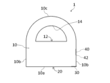
- FIG. 1 is a perspective view showing one embodiment of a tape cutter according to the present invention
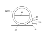
- FIG. FIG. 2 is a side view of the tape cutter of FIG. 1
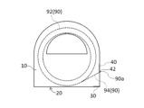
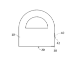
- FIG. 2 is a front view showing the tape cutter of FIG. 1
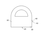
- Figure 2 is an end view of the tape cutter of Figure 1
- FIG. 3 is a side view for explaining an example of how to use the tape cutter of FIG. 1
- FIG. 3 is a side view for explaining an example of how to use the tape cutter of FIG. 1
- FIG. 3 is a side view for explaining an example of how to use the tape cutter of FIG. 1
- FIG. 3 is a side view for explaining an example of how to use the tape cutter of FIG. 1
- FIG. 3 is a side view for explaining an example of how to use the tape cutter of FIG. 1
- FIG. FIG. 11 is a side view for explaining another modified example of the sticking portion 40;
- FIG. 1, 2 and 3 are a perspective view, a side view and a front view, respectively, showing one embodiment of the tape cutter according to the present invention.
- FIG. 3 corresponds to a right side view of the tape cutter of FIG. 4 is an end view showing the tape cutter of FIG. 1.
- FIG. 3 corresponds to a right side view of the tape cutter of FIG. 4 is an end view showing the tape cutter of FIG. 1.
- the tape cutter 1 is a tape cutter that rotatably holds the adhesive tape 90, and is used to extend and cut the adhesive tape 90.
- the adhesive tape 90 is wound around an annular core. An adhesive surface is exposed on the back surface of the adhesive tape 90 .
- the adhesive tape 90 may be provided with an adhesive surface only on the back surface, or may be provided with an adhesive surface on both surfaces (front surface and back surface). Examples of the former include cellophane tape. Examples of the latter include, for example, double-sided tape.
- the adhesive surface of the double-sided tape may be exposed only on the back surface, or may be exposed on both surfaces.
- the former double-sided tape has a release paper attached to its surface.
- the adhesive tape 90 is a double-sided tape with an adhesive surface exposed only on the back side. 1 to 3, illustration of the adhesive tape 90 is omitted.
- the adhesive tape 90 consists of a wound portion 92 and a drawer portion 94 (see FIG. 4).
- the wound portion 92 is a portion wound around the core of the adhesive tape 90 and has an annular shape as a whole.
- the back surface of each portion of the winding portion 92 is adhered to the surface of another portion of the winding portion 92 or to the core.
- the pull-out portion 94 is a portion of the adhesive tape 90 pulled out from the wound portion 92 . Therefore, the back surface of the lead-out portion 94 is attached neither to the surface of the winding portion 92 nor to the core.
- the tape cutter 1 includes a pair of side plate portions 10, a bottom plate portion 20, a cutting blade 30, and an adhering portion 40.
- the pair of side plate portions 10 covers the adhesive tape 90 from both sides.
- FIG. 4 shows an end face that is parallel to the side plate portions 10 and positioned between the pair of side plate portions 10 .
- a lower portion of each side plate portion 10 (in a side view, a portion below a straight line including an insertion portion 12 to be described later) is rectangular.
- the upper portion of each side plate portion 10 (the portion above the straight line in side view) has a semicircular shape.
- the side plate portion 10 may cover the entire adhesive tape 90 from the side, or may cover only a portion thereof.
- the side plate portion 10 may overlap the entire adhesive tape 90 or may overlap only a portion of the adhesive tape 90 in a side view.
- Each side plate portion 10 has a plate shape.
- a material for the side plate portion 10 for example, paper, plastic, metal, or wood can be used. Papers also include processed papers and cellulose nanofibers (CNF).
- the plastic may be a biodegradable plastic.
- An insertion portion 12 is connected to each side plate portion 10 .
- the insertion part 12 is inserted inside the core of the adhesive tape 90 so that the adhesive tape 90 does not come off the tape cutter 1 .
- the insertion portion 12 has a plate shape.
- the thickness direction of the insertion portion 12 is perpendicular to the thickness direction of the side plate portion 10 .
- the two insertion portions 12 are fixed to each other in an overlapping state. Thereby, the center portions of the pair of side plate portions 10 are connected by the insertion portion 12 .
- the “central portion” is a portion of the side plate portion 10 other than the peripheral edge.
- Each insertion portion 12 is preferably formed integrally with the side plate portion 10 .
- the material of the insertion portion 12 may be the same as or different from the material of the side plate portion 10 .
- Each side plate portion 10 has a semicircular opening 14 .
- An opening 14 is formed in the upper portion of each side plate portion 10 .
- the opening 14 is sized to allow insertion of a finger. Therefore, the tape cutter 1 can be used while holding the finger in the opening 14 .
- the insertion portion 12 is connected to the lower end of the opening portion 14 .
- the bottom plate portion 20 is connected to the lower end 10 a of each side plate portion 10 . Thereby, the lower ends 10 a of the pair of side plate portions 10 are connected by the bottom plate portion 20 .
- the bottom plate portion 20 may be connected to the entire lower end 10a of each side plate portion 10, or may be connected to only a portion thereof.
- the bottom plate portion 20 has a plate shape.
- the thickness direction of the bottom plate portion 20 is perpendicular to the thickness direction of the side plate portion 10 and equal to the thickness direction of the insertion portion 12 .
- the bottom plate portion 20 is preferably formed integrally with the side plate portion 10 .
- the material of the bottom plate portion 20 may be the same as or different from that of the side plate portion 10 .
- the cutting blade 30 is provided at the end of the bottom plate portion 20 .
- the cutting blade 30 is fixed on the bottom plate portion 20 .
- the cutting blade 30 cuts the adhesive tape 90 while in contact with the surface of the adhesive tape 90 .
- a tip of the cutting blade 30 protrudes from the bottom plate portion 20 .
- the tip of the cutting blade 30 is separated from the winding portion 92 .
- the cutting blade 30 cuts the adhesive tape 90 leaving a drawn-out portion 94 of a certain length.
- the material of the cutting blade 30 may be the same as or different from the material of the side plate portion 10 .
- the cutting blade 30 may be formed integrally with the bottom plate portion 20 .
- the sticking part 40 is provided above the cutting blade 30 .
- the back surface of the adhesive tape 90 is attached to the attaching portion 40 with the end 90 a of the adhesive tape 90 (the lead-out portion 94 ) floating from the cutting blade 30 .
- the back surface of the adhesive tape 90 is attached to the tip portion 42 of the attaching portion 40 .
- the tip portion 42 is equal to the lower end of the sticking portion 40 .
- the tip portion 42 (the portion with which the back surface of the adhesive tape 90 contacts) may be flat or uneven.
- the width of the adhering portion 40 monotonically decreases toward the tip portion 42 .
- a width w ⁇ b>1 (see FIG. 3 ) of the tip portion 42 is smaller than the width of the adhesive tape 90 . That is, the width w1 is designed to be smaller than the width of the adhesive tape 90 that is assumed to be used in the tape cutter 1 .
- the width w1 is preferably 50% or less of the width of the adhesive tape 90, more preferably 20% or less.
- the sticking part 40 is connected to each side plate part 10 .
- the sticking portion 40 is connected to the side end 10 b of each side plate portion 10 .
- the side end 10b is a portion of the peripheral edge of the side plate portion 10 other than the lower end 10a, which is positioned at the lower portion.
- the side end 10b is linear.
- the side ends 10b of the pair of side plate portions 10 are connected by the sticking portion 40.
- the side ends 10b of the pair of side plate portions 10 are connected only by the sticking portion 40.
- the side ends 10b of the pair of side plate portions 10 are not connected to each other on the opposite side of the sticking portion 40.
- the upper ends 10c of the pair of side plate portions 10 are not connected.
- the upper end 10c is a portion of the peripheral edge of the side plate portion 10 other than the lower end 10a, which is positioned at the upper portion.
- the upper end 10c is curved.
- the distance d1 (see FIG. 3) from the cutting blade 30 to the sticking portion 40 (tip portion 42) in the vertical direction is preferably equal to or greater than the interval d2 between the pair of side plate portions 10.
- the vertical direction is equal to the thickness direction of the bottom plate portion 20 (the vertical direction in FIGS. 1 to 3).
- the distance d1 is preferably 10 mm or more, more preferably 15 mm or more.
- the tip portion 42 is located on the side end 10b of the side plate portion 10 .
- the tip portion 42 may or may not overlap the tip of the cutting blade 30 . That is, the tip portion 42 may be positioned directly above the tip of the cutting blade 30 or may be positioned obliquely above it. In the latter case, the distance (horizontal distance) from the tip of the cutting blade 30 to the tip 42 in plan view is preferably smaller than the distance d1.
- the sticking portion 40 has a plate shape.
- the thickness direction of the sticking portion 40 is perpendicular to both the thickness direction of the side plate portion 10 and the thickness direction of the bottom plate portion 20 .
- the thickness of the sticking portion 40 is preferably equal to the thickness of each side plate portion 10 .
- the sticking portion 40 is preferably formed integrally with the side plate portion 10 .
- the material of the sticking portion 40 may be the same as or different from the material of the side plate portion 10 .
- a sheet 50 of sufficient size is prepared, and the sheet 50 is cut into the shape shown in FIG.
- the sheet 50 is made of paper (cardboard).
- the cut sheet 50 includes a portion 10p that will become the side plate portion 10, a portion 12p that will become the insertion portion 12, a portion 20p that will become the bottom plate portion 20, a reinforcing portion 22, a portion 40p that will become the sticking portion 40, and an adhesive margin portion 44.
- a portion 14p to be the opening 14 is formed in the portion 10p. 5 shows the inner surfaces of the portion 10p, the portion 20p and the portion 40p (the surface on the side facing the adhesive tape 90 in the tape cutter 1).
- the sheet 50 is valley-folded along the fold line L1 so that the reinforcing portion 22 overlaps the portions 10p and 20p.
- the fold L1 is located at the boundary between the portions 10p, 20p and the reinforcing portion 22.
- a portion of the reinforcing portion 22 overlapping the portion 10p constitutes the side plate portion 10 together with the portion 10p.
- a portion of the reinforcing portion 22 that overlaps the portion 20p constitutes the bottom plate portion 20 together with the portion 20p.
- illustration of the reinforcing portion 22 is omitted.
- a cutting blade 30 is attached to a portion of the reinforcing portion 22 that overlaps the portion 20p.
- the sheet 50 is valley-folded at right angles along the fold L2, the fold L3, the fold L4, and the fold L5.
- Fold L2 is located at the boundary between portion 10p and portion 12p.
- Fold L3 is located at the boundary between portion 10p and portion 40p.
- the fold L4 is located at the boundary between the portion 40p and the margin portion 44.
- Fold L5 is located at the boundary between portion 10p and portion 20p.
- the adhesive tape 90 is arranged between the pair of portions 10p so that the portion 12p is inserted inside the core of the adhesive tape 90. As shown in FIG. After that, the pair of portions 12p are fixed together.
- the paste margin portion 44 is fixed to the inner surface of the portion 10p (the shaded portion 44a in FIG. 6). These fixings can be performed, for example, using an adhesive. As described above, the tape cutter 1 shown in FIGS. 1 to 4 is obtained. Thus, in this example, the side plate portion 10, the bottom plate portion 20, and the sticking portion 40 are formed from one sheet (cardboard).
- the adhesive tape 90 (drawer portion 94 ) is pinched with fingers, and the adhesive tape 90 is peeled off from the sticking portion 40 and then pulled along the bottom plate portion 20 . As a result, the adhesive tape 90 is let out from between the bottom plate portion 20 and the sticking portion 40 .
- the adhesive tape 90 is cut by pressing the surface of the adhesive tape 90 against the tip of the cutting blade 30 .
- the back surface of the adhesive tape 90 is adhered to the adhered portion 40 again. At this time, it is preferable that the end 90 a of the adhesive tape 90 protrudes from the tip portion 42 .
- the lead-out portion 94 is adhered only to the adhered portion 40 . That is, the tape cutter 1 is configured so that the pull-out portion 94 is not attached to a portion of the tape cutter 1 other than the attached portion 40 . In this way, the adhesive tape 90 can be fed out from the tape cutter 1 to obtain cut pieces of a desired length.
- the tape cutter 1 is provided with an adhering portion 40 above the cutting blade 30 .
- the back surface of the adhesive tape 90 is attached to the attaching portion 40 with the end 90 a of the adhesive tape 90 floating from the cutting blade 30 .
- a gap is secured between the end 90a of the adhesive tape 90 and the cutting blade 30, making it easier to pick up the adhesive tape 90 with fingers. Therefore, the tape cutter 1 is realized in which the end 90a of the adhesive tape 90 can be easily picked up when the adhesive tape 90 is fed out.
- the adhesive tape 90 By adhering the adhesive tape 90 to the adhering portion 40 in this way, it is possible to make it difficult for the adhesive tape 90 to unwind (the drawer portion 94 returns to the wound portion 92).
- the adhesive tape 90 can be pinched at a position away from the cutting blade 30, the fingers are less likely to touch the cutting blade 30 when the adhesive tape 90 is fed out. Therefore, the safety of the tape cutter 1 can be enhanced.
- the distance d1 is equal to or greater than the distance d2 between the pair of side plate portions 10 .
- the distance d1 is preferably 10 mm or more, more preferably 15 mm or more.
- the distance d1 is preferably 50 mm or less.
- the sticking part 40 is connected to each side plate part 10 .
- the sticking portion 40 can also function as a member for maintaining the shape of the tape cutter 1 (the shape in which a pair of side plate portions 10 are opposed to each other at a predetermined interval).
- the sticking portion 40 is connected to the side end 10b of each side plate portion 10. This makes it easier to align the tip portion 42 of the sticking portion 40 with the side edge 10 b of the side plate portion 10 .
- the tip portion 42 is positioned on the side end 10b of the side plate portion 10 in a side view. In this case, since the tip portion 42 does not enter the space sandwiched between the pair of side plate portions 10, it is advantageous in making it easier to pick up the adhesive tape 90 stuck to the sticking portion 40 with fingers.
- the width w1 of the tip portion 42 is smaller than the width of the adhesive tape 90. In this case, by changing the width w1, it is possible to adjust the contact area between the tip portion 42 and the adhesive tape 90, and thus the adhesive force between the sticking portion 40 and the adhesive tape 90.
- FIG. This increases options for the material of the adhering portion 40, making it easier to integrally form the adhering portion 40 with other portions (the side plate portion 10, the bottom plate portion 20, and/or the cutting blade 30).
- the width w1 is preferably 50% or less of the width of the adhesive tape 90, and more preferably 20% or less. On the other hand, if the width w1 is too small, the adhesive force between the sticking portion 40 and the adhesive tape 90 may become insufficient. From this point of view, the width w1 is preferably 5% or more of the width of the adhesive tape 90 .
- the width of the sticking portion 40 monotonically decreases as it approaches the tip portion 42 .
- the thickness of the sticking portion 40 is equal to the thickness of each side plate portion 10, it becomes easier to form the side plate portion 10 and the sticking portion 40 from one sheet having a uniform thickness.
- the sticking portion 40 is made of the same material as the pair of the side plate portion 10 and the bottom plate portion 20, the side plate portion 10, the bottom plate portion 20 and the sticking portion 40 can be easily formed integrally.
- the manufacturing process of the tape cutter 1 can be simplified, thereby reducing the manufacturing cost of the tape cutter 1.
- the sticking portion 40 When the sticking portion 40 is made of paper, the weight of the sticking portion 40 and the tape cutter 1 can be reduced.
- the tape cutter 1 contains CNF as a material, it is advantageous for reducing the weight and increasing the strength of the tape cutter 1 . Moreover, using CNF also contributes to reduction of environmental load.
- the side ends 10b of the pair of side plate portions 10 are connected to each other only by the sticking portion 40.
- a member for connecting the side ends 10b of the side plate portion 10 is unnecessary. Thereby, the material of the tape cutter 1 can be saved. This also contributes to the reduction of manufacturing cost of the tape cutter 1 .
- the upper ends 10c of the pair of side plate portions 10 are not connected. In this case, a member for connecting the upper ends 10c of the side plate portions 10 is not required. Thereby, the material for the tape cutter 1 can be further saved.
- the seat 50 is provided with a reinforcing portion 22 .
- the strength of a portion of the tape cutter 1 (periphery of the cutting blade 30) can be increased.
- providing the reinforcing portion 22 is not essential. If the reinforcement part 22 is not provided, the material of the tape cutter 1 can be saved.
- the present invention is not limited to the above embodiments, and various modifications are possible.
- the case where the tip portion 42 of the sticking portion 40 is positioned on the side end 10b of the side plate portion 10 in side view is illustrated.
- the tip portion 42 may protrude from the side edge 10b of the side plate portion 10 in a side view.
- the sticking portion 40 is inclined downward toward the outside of the side plate portion 10 .
- the sticking portion 40 may be entirely slanted, or only a portion thereof (a portion including the tip portion 42) may be slanted.
- the adhesive tape 90 is attached to the attaching portion 40 outside the side plate portion 10 . Therefore, it becomes easier to pick up the end 90a of the adhesive tape 90 . Further, when the adhering portion 40 is inclined downward toward the outside of the side plate portion 10, the adhering portion 40 with respect to the back surface of the adhesive tape 90 is more inclined than when the adhering portion 40 is not inclined. The angle is near a right angle. Thereby, the adhesive tape 90 can be stably stuck to the sticking portion 40 .
- the tip portion 42 of the sticking portion 40 may be bent as shown in FIG. 11, for example.
- the tip portion 42 is bent outward from the side plate portion 10 .
- the tip portion 42 can easily protrude from the side edge 10 b of the side plate portion 10 .
- the tip portion 42 may be bent inside the side plate portion 10 .
- the width w1 of the tip portion 42 is smaller than the width of the adhesive tape 90 is exemplified.
- the width w1 may be equal to the width of the adhesive tape 90 or may be greater than the width of the adhesive tape 90 .
- the width w1 may be equal to the distance d2 between the pair of side plate portions 10. As shown in FIG.
- the sticking portion 40 is fixed to the side plate portion 10 .
- the sticking portion 40 may be provided detachably with respect to the side plate portion 10 .
- the sticking portion 40 may be configured to be retrofitted to an existing tape cutter.
Landscapes
- Adhesive Tape Dispensing Devices (AREA)
- Nonmetal Cutting Devices (AREA)
Priority Applications (2)
| Application Number | Priority Date | Filing Date | Title |
|---|---|---|---|
| PCT/JP2023/003578 WO2023063436A2 (ja) | 2023-02-03 | 2023-02-03 | テープカッター |
| JP2023508473A JP7350410B2 (ja) | 2023-02-03 | 2023-02-03 | テープカッター |
Applications Claiming Priority (1)
| Application Number | Priority Date | Filing Date | Title |
|---|---|---|---|
| PCT/JP2023/003578 WO2023063436A2 (ja) | 2023-02-03 | 2023-02-03 | テープカッター |
Publications (2)
| Publication Number | Publication Date |
|---|---|
| WO2023063436A2 true WO2023063436A2 (ja) | 2023-04-20 |
| WO2023063436A3 WO2023063436A3 (ja) | 2023-06-22 |
Family
ID=85987815
Family Applications (1)
| Application Number | Title | Priority Date | Filing Date |
|---|---|---|---|
| PCT/JP2023/003578 Ceased WO2023063436A2 (ja) | 2023-02-03 | 2023-02-03 | テープカッター |
Country Status (2)
| Country | Link |
|---|---|
| JP (1) | JP7350410B2 (https=) |
| WO (1) | WO2023063436A2 (https=) |
Family Cites Families (4)
| Publication number | Priority date | Publication date | Assignee | Title |
|---|---|---|---|---|
| JPH0948553A (ja) * | 1995-08-07 | 1997-02-18 | Nichiban Co Ltd | 容器入巻テ−プ |
| JP3629667B2 (ja) * | 1995-11-27 | 2005-03-16 | ニチバン株式会社 | 容器入巻テ−プ |
| JP2003020161A (ja) * | 2001-07-10 | 2003-01-21 | Nichiban Co Ltd | 粘着テ−プ容器 |
| JP6688677B2 (ja) * | 2016-05-18 | 2020-04-28 | ニチバン株式会社 | 粘着テープ用ホルダ |
-
2023
- 2023-02-03 WO PCT/JP2023/003578 patent/WO2023063436A2/ja not_active Ceased
- 2023-02-03 JP JP2023508473A patent/JP7350410B2/ja active Active
Also Published As
| Publication number | Publication date |
|---|---|
| JPWO2023063436A1 (https=) | 2023-04-20 |
| JP7350410B2 (ja) | 2023-09-26 |
| WO2023063436A3 (ja) | 2023-06-22 |
Similar Documents
| Publication | Publication Date | Title |
|---|---|---|
| JP4898548B2 (ja) | フィルム分配ケースおよびフィルム入りケース | |
| KR20090115183A (ko) | 필름용 수납 상자 | |
| WO2023063436A2 (ja) | テープカッター | |
| JP2011246144A5 (https=) | ||
| JP7604040B2 (ja) | 両面テープ及びテープカッター | |
| US5423464A (en) | Wrap film containing box and manufacturing method therefor | |
| CN103561964B (zh) | 将堆叠片材保持在一起的装置 | |
| JP7412831B2 (ja) | テープカッター | |
| JP7473929B2 (ja) | テープカッター | |
| JP2013244080A (ja) | ロールペーパーボックス | |
| JP4874866B2 (ja) | ロール状フィルム体の収納箱 | |
| JP2007112503A (ja) | 衛生用紙収納用カートン | |
| JP4913417B2 (ja) | 衛生用紙収納用カートン | |
| KR200486417Y1 (ko) | 패키징 | |
| JP6322373B2 (ja) | ラップフィルム収納箱 | |
| CN222070875U (zh) | 一种遮光纸结构 | |
| CN223059488U (zh) | 一种烟盒折叠纸及烟盒 | |
| KR102161936B1 (ko) | 벽걸이형 칼렌더 및 그 제조 방법 | |
| JP5694190B2 (ja) | カートン及び包装物供給体 | |
| JP6322461B2 (ja) | シート包装箱 | |
| KR200355844Y1 (ko) | 띠지 케이스 | |
| JP2017205830A (ja) | 粘着テープ用ホルダ | |
| JPH1016948A (ja) | クッキングペーパーの収納箱 | |
| JP2004010139A (ja) | フィルム収納箱 | |
| JPH11334982A (ja) | 粘着テープカッター |
Legal Events
| Date | Code | Title | Description |
|---|---|---|---|
| WWE | Wipo information: entry into national phase |
Ref document number: 2023508473 Country of ref document: JP |
|
| 121 | Ep: the epo has been informed by wipo that ep was designated in this application |
Ref document number: 23719258 Country of ref document: EP Kind code of ref document: A2 |
|
| NENP | Non-entry into the national phase |
Ref country code: DE |
|
| 122 | Ep: pct application non-entry in european phase |
Ref document number: 23719258 Country of ref document: EP Kind code of ref document: A2 |