WO2023063055A1 - 移動玩具 - Google Patents
移動玩具 Download PDFInfo
- Publication number
- WO2023063055A1 WO2023063055A1 PCT/JP2022/035546 JP2022035546W WO2023063055A1 WO 2023063055 A1 WO2023063055 A1 WO 2023063055A1 JP 2022035546 W JP2022035546 W JP 2022035546W WO 2023063055 A1 WO2023063055 A1 WO 2023063055A1
- Authority
- WO
- WIPO (PCT)
- Prior art keywords
- inclined surface
- mobile toy
- synthetic rubber
- contact member
- rotating body
- Prior art date
- Legal status (The legal status is an assumption and is not a legal conclusion. Google has not performed a legal analysis and makes no representation as to the accuracy of the status listed.)
- Ceased
Links
Images


Classifications
-
- A—HUMAN NECESSITIES
- A63—SPORTS; GAMES; AMUSEMENTS
- A63H—TOYS, e.g. TOPS, DOLLS, HOOPS OR BUILDING BLOCKS
- A63H3/00—Dolls
- A63H3/36—Details; Accessories
-
- A—HUMAN NECESSITIES
- A63—SPORTS; GAMES; AMUSEMENTS
- A63H—TOYS, e.g. TOPS, DOLLS, HOOPS OR BUILDING BLOCKS
- A63H13/00—Toy figures with self-moving parts, with or without movement of the toy as a whole
-
- A—HUMAN NECESSITIES
- A63—SPORTS; GAMES; AMUSEMENTS
- A63H—TOYS, e.g. TOPS, DOLLS, HOOPS OR BUILDING BLOCKS
- A63H15/00—Other gravity-operated toy figures
- A63H15/02—Figures staggering down an inclined path by means of the gravity effect
Definitions
- the present invention relates to a mobile toy that moves on an inclined surface.
- Patent Document 1 Japanese Utility Model Laid-Open No. 05-020792 (Patent Document 1) describes a walking doll that includes a tubular body portion and a pair of legs that are swingably provided inside the tubular body portion. there is In this walking doll, a pair of legs alternately steps forward on a gentle slope surface and descends the slope by repeating the motion.
- a mobile toy that moves on an inclined surface, comprising: a main body; a facing member provided on the main body and facing the inclined surface; and a rotating shaft provided on the facing member.
- a rotating body a first contact member provided on the moving direction side when the opposing member moves on the inclined surface and capable of coming into contact with the inclined surface, and a moving direction side centering on the rotating body of the opposing member a second contact member provided on the opposite side to the inclined surface and capable of contacting the inclined surface, wherein the rotating body and the first contact member contact the inclined surface while moving on the inclined surface; and a first state in which the second contact member is separated from the inclined surface; and a first state in which the rotating body and the second contact member are in contact with the inclined surface and the first contact member is separated from the inclined surface. 2 states.
- FIG. 2 is a view in the direction of arrow A in FIG. 1; It is a B arrow directional view of FIG. 4 is a cross-sectional view taken along line CC of FIG. 3; FIG. 4 is a cross-sectional view taken along line DD of FIG. 3;
- FIG. 1 is an exploded perspective view of a mobile toy; FIG. FIG. 4 is an operation explanatory view of the mobile toy viewed from the side; FIG. 4 is an operation explanatory diagram of the mobile toy viewed from the front;
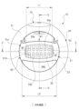
- FIG. 1 is a view of the mobile toy viewed from the front
- FIG. 2 is a view from arrow A in FIG. 1
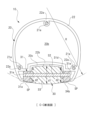
- FIG. 3 is a view from arrow B in FIG. 1
- FIG. 4 is a cross section along line CC in FIG. 5 is a cross-sectional view along line DD in FIG. 3
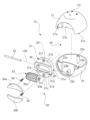
- FIG. 6 is an exploded perspective view of the mobile toy
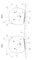
- FIG. 4A and 4B are operation explanatory diagrams of the toy viewed from the front.
- the mobile toy 10 shown in FIGS. 1 to 8 is, for example, a toy that descends by its own weight on a gently inclined plane SL (see FIG. 7) of ⁇ ° (about 5°). This mobile toy 10 does not have a power source and moves downward on the inclined surface SL by its own weight.
- the mobile toy 10 has a hollow main body 20.
- the main body 20 includes a first main body 21 made of a resin material such as plastic in a substantially bowl shape, and a second main body 22 made of a resin material such as plastic like the first main body 21 and formed in a substantially bowl shape. I have. By abutting these first and second main bodies 21 and 22, the main body 20 is formed in a substantially spherical shape.
- the first main body 21 is arranged on the moving direction side of the mobile toy 10, that is, on the front side in the moving direction.
- the second main body 22 is arranged on the side opposite to the moving direction side of the mobile toy 10, that is, on the rear side in the moving direction.
- a character face FC is provided on the outer surface of the first main body 21 by printing or the like. That is, the character's face FC is provided on the moving direction side of the main body 20 .
- the first main body 21 is provided with a total of three engaging protrusions 21a (only one is shown in FIG. 5 and only two are shown in FIG. 6).
- the second main body 22 is provided with a total of three engaging recesses 22a (only one is shown in FIG. 5). The first and second main bodies 21 and 22 are assembled together by inserting the engaging projections 21a into the engaging recesses 22a.
- first and second main bodies 21 and 22 are not easily separated from each other.
- a partition wall 20a is provided inside the body 20 inside the body 20 .
- the partition wall 20a is formed of a first partition wall 21b forming the first main body 21 and a second partition wall 22b forming the second main body 22.
- the partition wall 20a divides the inside of the main body 20 into a hollow chamber 20b on the side away from the inclined surface SL and a roller mechanism accommodation chamber 20c on the side close to the inclined surface SL.
- roller mechanism 30 is accommodated in the roller mechanism accommodation chamber 20c.
- a first screw hole (female screw) 21c is provided in the first main body 21 arranged in front of the moving toy 10 in the moving direction.
- a second screw hole (female screw) 22c is provided in the second main body 22 arranged behind the moving toy 10 in the moving direction. Fixing screws (male screws) SC are screwed into these first and second screw holes 21c and 22c, respectively. Thereby, the roller mechanism 30 is fixed to both the first and second main bodies 21 and 22 forming the main body 20 .
- the first body 21 is arranged forward in the movement direction and the second body 22 is arranged rearward in the movement direction.
- the mobile toy 10 can move downward on the inclined plane SL. Therefore, the character's face FC can be provided on the outer surface of the second main body 22 .
- the character's face FC can be provided on the opposite side of the main body 20 from the moving direction side.
- the character's face FC can be provided on both the outer surfaces of the first and second main bodies 21 and 22 .
- the roller mechanism 30 housed in the roller mechanism housing chamber 20c moves the main body 20 composed of the first and second main bodies 21 and 22 on the inclined plane SL while swinging back and forth and left and right. (see FIGS. 7 and 8).
- the roller mechanism 30 is a functional component necessary to improve the interest of the mobile toy 10. As shown in FIG.
- the portion of the mobile toy 10 closer to the inclined surface SL becomes heavy. Therefore, as shown in FIG. 5, the center of gravity G of the mobile toy 10 is located closer to the partition wall 20a (closer to the roller mechanism 30 and inclined surface SL) than the central portion of the main body 20 is.
- the moving toy 10 moves downward on the slope SL in an interesting motion by moving the center of gravity G in the front-rear direction and in the left-right direction.
- the roller mechanism 30 includes a base member 31 made of a resin material such as plastic and having a substantially disk shape.
- the base member 31 corresponds to a facing member in the present invention, and is provided on the main body 20 and faces the inclined surface SL.
- a roller support portion 31a is provided in the central portion of the base member 31 .
- a line segment extending in the moving direction of the mobile toy 10 is defined as a first line segment LN1
- a line segment orthogonal to the first line segment LN1 is defined as a second line segment LN2
- the longitudinal direction of the roller support portion 31a coincides with the extending direction of the second line segment LN2.
- the roller support portion 31a is provided with a roller housing hole 31d formed in a substantially elliptical shape.
- the longitudinal direction of the roller accommodation hole 31d also coincides with the extending direction of the second line segment LN2, and the roller accommodation hole 31d penetrates the base member 31 in the thickness direction.
- roller support portion 31a is provided with a pair of shaft holes 31e extending in the extending direction of the second line segment LN2. Both longitudinal sides of a rotating shaft 32 made of a round steel bar are inserted into the pair of shaft holes 31e.
- the rotary shaft 32 rotatably supports the barrel-shaped roller 33 so that the barrel-shaped roller 33 can rotate clockwise and counterclockwise as shown in FIG. 5 inside the roller housing hole 31d. It's becoming
- the barrel-shaped roller 33 housed in the roller housing hole 31d is made of a resin material such as plastic and has a substantially barrel shape. Specifically, the barrel-shaped roller 33 is formed in a shape in which the diameter gradually decreases from the center in the longitudinal direction toward both sides in the longitudinal direction. That is, as shown in FIG. 4, the longitudinal center of the barrel-shaped roller 33 has a diameter dimension d1, and both longitudinal sides of the barrel-shaped roller 33 have a diameter dimension d2 smaller than the diameter dimension d1. (d2 ⁇ d1).
- the barrel-shaped roller 33 corresponds to the rotating body in the present invention.
- the barrel-shaped roller 33 rotates about a rotating shaft 32 provided on the base member 31 and can smoothly roll on the inclined surface SL.
- the outer peripheral surface of the barrel-shaped roller 33 is provided with a plurality of recesses 33a. These recessed portions 33 a extend in the circumferential direction of the barrel-shaped roller 33 and are arranged side by side in the axial direction of the barrel-shaped roller 33 .
- the barrel-shaped roller 33 can smoothly roll without rattling even on the gently inclined surface SL. ing. If the barrel-shaped roller 33 were provided with a plurality of recesses extending in the axial direction, the barrel-shaped roller 33 would roll on the inclined surface SL while rattling, and the mobile toy 10 would stop on the inclined surface SL. Something like that can happen.
- the plurality of concave portions 33a function as so-called “thickening" when forming the barrel-shaped roller 33. That is, the plurality of recesses 33a effectively suppress the occurrence of sink marks, voids, and the like in the barrel-shaped roller 33 during hardening after the barrel-shaped roller 33 is injection molded. Therefore, it is possible to prevent the occurrence of distortion during molding of the barrel-shaped roller 33, and thereby realize the barrel-shaped roller 33 with high dimensional accuracy.
- the barrel-shaped roller 33 made of plastic and providing a plurality of concave portions 33a, not only the weight of the barrel-shaped roller 33 is reduced, but also the frictional force of the barrel-shaped roller 33 against the inclined surface SL is reduced. . Therefore, the barrel-shaped rollers 33 do not increase the movement resistance of the mobile toy 10 with respect to the inclined surface SL. Therefore, the mobile toy 10 can move smoothly on the slope SL.
- the outer peripheral surface of the barrel-shaped roller 33 is arc-shaped with a relatively large radius of curvature R.
- the radius of curvature R of the outer peripheral surface of the barrel-shaped roller 33 is larger than the radius of curvature (not shown) of the outer peripheral surface of the substantially spherical main body 20 .
- the mobile toy 10 swings left and right on the inclined surface SL and moves downward on the inclined surface SL by its own weight. Therefore, the interest of the mobile toy 10 is improved.
- the screw head of the fixing screw SC also enters inside the screw insertion hole 31f.
- the first synthetic rubber 34a and the second synthetic rubber 34b formed in a flat plate shape can be attached to the first recessed portion 31b and the second recessed portion 31c, respectively.
- the first recessed portion 31b and the second recessed portion 31c have the same shape and are formed in a crescent shape.
- a crescent-shaped first synthetic rubber 34a and a second synthetic rubber 34b made of silicone or the like are attached to the first recessed portion 31b and the second recessed portion 31c, respectively.
- the first synthetic rubber 34a and the second synthetic rubber 34b are also formed in the same shape.
- the first recessed portion 31b and the second recessed portion 31c and the first synthetic rubber 34a and the second synthetic rubber 34b, which are formed in the same shape are not necessarily the same. , may be different from each other, as long as it is possible to realize the back-and-forth swinging of the mobile toy 10 on the inclined surface SL, which will be described later.
- a first synthetic rubber 34a is attached to the first recessed portion 31b on the front side of the base member 31 in the moving direction, and a second synthetic rubber 34b is attached to the second recessed portion 31c on the rear side of the base member 31 in the moving direction.
- the first synthetic rubber 34a and the second synthetic rubber 34b are fixed to the first recessed portion 31b and the second recessed portion 31c by double-sided tape or the like (not shown), respectively.
- the first synthetic rubber 34a and the second synthetic rubber 34b extend from the base member 31 to the inclined surface SL (downward in the figure, the direction away from the surface facing the inclined surface of the base member 31). It protrudes slightly toward the Therefore, the first synthetic rubber 34a and the second synthetic rubber 34b can come into contact with the inclined surface SL as the mobile toy 10 moves on the inclined surface SL.
- the first synthetic rubber 34a corresponds to the first contact member in the present invention, and is provided on the moving direction side of the base member 31.
- the second synthetic rubber 34b corresponds to the second contact member in the present invention, and is provided on the opposite side of the base member 31 with respect to the barrel-shaped roller 33 in the moving direction.
- the first synthetic rubber 34a and the second synthetic rubber 34b are arranged so as to be mirror-symmetrical on both sides of the barrel-shaped roller 33 in the moving direction of the mobile toy 10 (see FIG. 3). ).
- the barrel-shaped roller 33 protrudes from the base member 31 more than the first synthetic rubber 34a and the second synthetic rubber 34b. Specifically, the barrel-shaped roller 33 protrudes more than the first synthetic rubber 34a and the second synthetic rubber 34b by the height dimension H (for example, about 2.0 mm).
- the first synthetic rubber 34a and the second synthetic rubber 34b can come into contact with the inclined surface SL as the mobile toy 10 swings on the inclined surface SL in the front-rear direction (see FIG. 7). ing.
- the first synthetic rubber 34a and the second synthetic rubber 34b are made of rubber such as silicone, and the barrel-shaped roller 33 is made of plastic. Therefore, the frictional force of the first synthetic rubber 34a and the second synthetic rubber 34b with respect to the inclined surface SL is greater than the frictional force of the barrel-shaped roller 33 with respect to the inclined surface SL. That is, the first synthetic rubber 34a and the second synthetic rubber 34b are more difficult to slip on the inclined surface SL than the barrel-shaped roller 33 is.
- the length L1 of the barrel-shaped roller 33 is the first synthetic rubber 34a and the first synthetic rubber 34a. It is shorter than the length L2 of the second synthetic rubber 34b (L1 ⁇ L2). Further, in the portion of the roller support portion 31a of the base member 31 and on both sides in the longitudinal direction of the barrel-shaped roller 33, the synthetic rubber non-installed portion (contact member non-installed portion) where the first synthetic rubber 34a and the second synthetic rubber 34b are not installed. Part) SP is provided.
- the first synthetic rubber 34a and the second synthetic rubber 34b are spaced apart from each other with the barrel-shaped roller 33 as the center.
- the synthetic rubber non-installed portion SP is a region where the first synthetic rubber 34a and the second synthetic rubber 34b are not installed in a protruding state, the base member 31 faces the inclined surface, and thus the inclined surface SL and the inclined surface SL. becomes a region where contact with the inclined surface SL is prevented or suppressed.
- the right end portion and the left end portion of the first synthetic rubber 34a and the second synthetic rubber 34b are individually tilted as the mobile toy 10 swings in the horizontal direction on the inclined surface SL (see FIG. 8).
- the mobile toy 10 descends on the inclined surface SL while meandering in the horizontal direction in small increments. Therefore, this also improves the interest of the mobile toy 10 .
- the synthetic rubber non-installed portion (contact member non-installed portion) SP is provided, the generation of frictional force in the direction perpendicular to the moving direction is suppressed, and the movement is prevented from being stopped by the frictional force. can be suppressed.
- the first synthetic rubber 34a and the second synthetic rubber 34b are each formed in a crescent shape, and the width of the central portion in the longitudinal direction of the first synthetic rubber 34a and the second synthetic rubber 34b
- the dimension w1 is larger than the width dimension w2 on both sides in the longitudinal direction (w1>w2). That is, the longitudinal central portions of the first synthetic rubber 34a and the second synthetic rubber 34b are wider than both longitudinal sides.
- the first synthetic rubber 34a in front of the movement direction is particularly the central part in the longitudinal direction and the front part in the movement direction ( The shaded area in FIG. 3) is easily worn. Therefore, the width dimension w1 of the central portion in the longitudinal direction of the first synthetic rubber 34a is made larger than the width dimension w2 of both sides in the longitudinal direction, and the portion of the central portion in the longitudinal direction of the first synthetic rubber 34a near the barrel-shaped roller 33 is also inclined.
- the SL is made contactable so that the function as the first synthetic rubber 34a can be exhibited for a long period of time.
- the mobile toy 10 can swing back and forth on the inclined surface SL for a long period of time.
- the same thing as described above can be applied to the second synthetic rubber 34b.
- the mobile toy 10 is placed on the inclined surface SL with the first body 21 provided with the character's face FC facing forward in the movement direction. Then, while the barrel-shaped roller 33 rotates, the center of gravity G of the mobile toy 10 moves in the moving direction. Then, the mobile toy 10 is tilted as indicated by the dashed arrow R1 and assumes a forward tilting posture. As a result, while the barrel-shaped roller 33 is in contact with the inclined surface SL, the first synthetic rubber 34a is brought into contact with the inclined surface SL and the brake is applied (first state). At this time, the second synthetic rubber 34b is separated from the inclined surface SL.
- the mobile toy 10 is now tilted as indicated by the dashed arrow R2 to assume a backward tilting posture. That is, the center of gravity G moves in the direction opposite to the movement direction. Therefore, the second synthetic rubber 34b contacts the inclined surface SL while the barrel-shaped roller 33 is in contact with the inclined surface SL (second state). At this time, the first synthetic rubber 34a is separated from the inclined surface SL.
- the barrel-shaped roller 33 rotates, and the mobile toy 10 descends on the slope SL by its own weight. Then, the mobile toy 10 is in a forward leaning posture as shown in action (3) in FIG. 7 (the same state as action (1)). After the action (3) in FIG. 7, the mobile toy 10 is in a backward tilted posture as shown in action (4) in FIG. 7 (the same state as the action (2)).
- the period from the state of action (1) to the state of action (3) is "one cycle" of the rocking motion of the mobile toy 10 in the front-rear direction.
- “one cycle” of the rocking motion of the mobile toy 10 is expressed as a long "one cycle” like a solid arrow.
- "one cycle" of the rocking motion of the mobile toy 10 is extremely short with a movement distance of several millimeters.
- the mobile toy 10 placed on the inclined surface SL repeatedly swings back and forth, as indicated by actions (1) to (4), and performs interesting actions. moves downward on the inclined plane SL by its own weight. In other words, the mobile toy 10 alternately repeats the first forward-leaning state and the second backward-leaning state, and moves downward on the slope SL.
- the movable toy 10 moves left and right as shown in actions (5) and (6). It also sways and sways. In other words, the mobile toy 10 performs more interesting motions such as rocking motion in the front-rear direction and rocking motion in the left-right direction.
- the mobile toy 10 tilts to the right as indicated by the dashed arrow R3, as shown in action (5). That is, the center of gravity G moves to the right in the moving direction.
- the mobile toy 10 is inclined leftward as indicated by the dashed arrow R4, as shown in action (6). That is, the center of gravity G moves to the left in the moving direction.
- the shape of the barrel-shaped roller 33 is formed such that the diameter gradually decreases from the center in the longitudinal direction toward both sides in the longitudinal direction. Therefore, the center of gravity G of the mobile toy 10 can easily move to the right and left in the moving direction. Therefore, even if the inclined surface SL is not inclined to the right or left in the moving direction, the movable toy 10 moves forward and backward as described above as the first synthetic rubber 34a and the second synthetic rubber 34b come into contact with the inclined surface SL. Performs an interesting action such as adding a horizontal rocking motion to the vertical rocking motion.
- the movable toy 10 moves downward on the inclined surface SL while swinging back and forth and left and right due to the function of the roller mechanism 30 .
- the mobile toy 10 performs a more complicated rocking motion depending on the shape (concave shape or convex shape) of the inclined surface SL, the angle of the inclined surface SL, and the material of the inclined surface SL (difference in coefficient of friction), the mobile toy 10 performs a more complicated rocking motion.
- the second synthetic rubber 34b behind the moving direction does not contact the inclined surface SL, and only the first synthetic rubber 34a ahead of the moving direction repeats contact with and separation from the inclined surface SL to sway little by little.
- the rotation of the shaped roller 33 can also perform the operation of descending the inclined surface SL.
- the present invention is not limited to the above-described embodiments, and can be modified in various ways without departing from the spirit of the present invention.
- the first synthetic rubber 34a and the second synthetic rubber 34b are both made of the same material (such as silicone), but the present invention is not limited to this.
- the synthetic rubber 34a and the second synthetic rubber 34b may be made of materials having different frictional forces with respect to the inclined surface SL.
Landscapes
- Toys (AREA)
Applications Claiming Priority (2)
| Application Number | Priority Date | Filing Date | Title |
|---|---|---|---|
| JP2021169963A JP7300487B2 (ja) | 2021-10-15 | 2021-10-15 | 移動玩具 |
| JP2021-169963 | 2021-10-15 |
Publications (1)
| Publication Number | Publication Date |
|---|---|
| WO2023063055A1 true WO2023063055A1 (ja) | 2023-04-20 |
Family
ID=84302616
Family Applications (1)
| Application Number | Title | Priority Date | Filing Date |
|---|---|---|---|
| PCT/JP2022/035546 Ceased WO2023063055A1 (ja) | 2021-10-15 | 2022-09-22 | 移動玩具 |
Country Status (3)
| Country | Link |
|---|---|
| JP (2) | JP7300487B2 (https=) |
| CN (1) | CN115445214B (https=) |
| WO (1) | WO2023063055A1 (https=) |
Citations (7)
| Publication number | Priority date | Publication date | Assignee | Title |
|---|---|---|---|---|
| JPS52141743A (en) * | 1976-04-13 | 1977-11-26 | Lesney Products Co Ltd | Improvement of toy |
| JPS6343598U (https=) * | 1986-09-08 | 1988-03-23 | ||
| US4764148A (en) * | 1986-10-13 | 1988-08-16 | T. K. Wong & Associates Limited | Toy adapted to crawl down a vertical surface |
| JPS63127694U (https=) * | 1987-02-13 | 1988-08-22 | ||
| JP2005296524A (ja) * | 2004-04-15 | 2005-10-27 | Bandai Co Ltd | 歩行体および歩行体の歩行方法 |
| CN203196308U (zh) * | 2013-05-06 | 2013-09-18 | 彭堂斌 | 沿斜面行走的玩具 |
| KR20150069428A (ko) * | 2013-12-13 | 2015-06-23 | 추현진 | 움직이는 학습교구 |
Family Cites Families (10)
| Publication number | Priority date | Publication date | Assignee | Title |
|---|---|---|---|---|
| CH266666A (de) * | 1948-02-10 | 1950-02-15 | Adler Emmi | Spielzeug. |
| CH269824A (de) * | 1948-05-03 | 1950-07-31 | Zimmermann Robert | Bewegliche Figur. |
| GB1213982A (en) * | 1967-02-17 | 1970-11-25 | Newfeld Ltd | Improvements in or relating to toys |
| JPS5428078Y2 (https=) * | 1976-02-06 | 1979-09-10 | ||
| JPS52114894U (https=) * | 1976-06-28 | 1977-08-31 | ||
| GB2196544B (en) * | 1986-10-13 | 1990-01-17 | Wong T K Ass Ltd | A toy |
| CN2099599U (zh) * | 1991-10-08 | 1992-03-25 | 刘艺 | 一种翻滚玩具 |
| JP3102206U (ja) * | 2003-12-10 | 2004-07-02 | 有限会社サスティーン | 起き上がりだんご玉 |
| JP5044716B1 (ja) * | 2011-09-20 | 2012-10-10 | 株式会社バンダイ | 対戦用走行玩具 |
| CN107715463A (zh) * | 2016-08-12 | 2018-02-23 | 颜茹玉 | 对战用行走玩具 |
-
2021
- 2021-10-15 JP JP2021169963A patent/JP7300487B2/ja active Active
-
2022
- 2022-09-14 CN CN202211114537.1A patent/CN115445214B/zh active Active
- 2022-09-22 WO PCT/JP2022/035546 patent/WO2023063055A1/ja not_active Ceased
-
2023
- 2023-06-19 JP JP2023100401A patent/JP7808071B2/ja active Active
Patent Citations (7)
| Publication number | Priority date | Publication date | Assignee | Title |
|---|---|---|---|---|
| JPS52141743A (en) * | 1976-04-13 | 1977-11-26 | Lesney Products Co Ltd | Improvement of toy |
| JPS6343598U (https=) * | 1986-09-08 | 1988-03-23 | ||
| US4764148A (en) * | 1986-10-13 | 1988-08-16 | T. K. Wong & Associates Limited | Toy adapted to crawl down a vertical surface |
| JPS63127694U (https=) * | 1987-02-13 | 1988-08-22 | ||
| JP2005296524A (ja) * | 2004-04-15 | 2005-10-27 | Bandai Co Ltd | 歩行体および歩行体の歩行方法 |
| CN203196308U (zh) * | 2013-05-06 | 2013-09-18 | 彭堂斌 | 沿斜面行走的玩具 |
| KR20150069428A (ko) * | 2013-12-13 | 2015-06-23 | 추현진 | 움직이는 학습교구 |
Also Published As
| Publication number | Publication date |
|---|---|
| JP7300487B2 (ja) | 2023-06-29 |
| CN115445214A (zh) | 2022-12-09 |
| JP2023059773A (ja) | 2023-04-27 |
| JP7808071B2 (ja) | 2026-01-28 |
| JP2023108067A (ja) | 2023-08-03 |
| CN115445214B (zh) | 2024-03-26 |
Similar Documents
| Publication | Publication Date | Title |
|---|---|---|
| US9281142B2 (en) | Keyboard device | |
| CN100438944C (zh) | 玩具的摩擦关节 | |
| JP2002221218A (ja) | 樹脂製ボールジョイント | |
| EP2058030A1 (en) | Playing device | |
| JP2010234050A (ja) | 玩具組立用ブロック | |
| CN110359794B (zh) | 用于车辆的门限位连杆装置 | |
| JP7300487B2 (ja) | 移動玩具 | |
| CN103826804B (zh) | 电动工具用滑动开关 | |
| JP4165897B1 (ja) | 組立ブロック玩具 | |
| KR20130047377A (ko) | 조립식 블록 완구 | |
| US8144242B2 (en) | Image sensor holder | |
| CN217567446U (zh) | 积木转动机构及其玩具 | |
| CN104645639B (zh) | 拼块玩具 | |
| JP6598942B1 (ja) | 自動車用サンバイザ | |
| JP6660806B2 (ja) | レジスタの操作ノブ装置 | |
| JP4185033B2 (ja) | 自動車用ドアチェッカ | |
| CN1610572A (zh) | 步行玩具 | |
| JP3646799B2 (ja) | 歩行ユニットおよび歩行玩具 | |
| RU2690057C1 (ru) | Блок конструктора и конструктор, содержащий набор этих блоков | |
| CN224166886U (zh) | 一种活动关节以及人偶 | |
| CN108211370B (zh) | 回旋球 | |
| CN210178744U (zh) | 一种转动连接机构及电子设备 | |
| JPH11351254A (ja) | ロ―ラ連結体及びこれを用いた直線案内装置 | |
| CN205877162U (zh) | 手动换挡机构 | |
| CN223147755U (zh) | 一种导向机构以及三维打印机 |
Legal Events
| Date | Code | Title | Description |
|---|---|---|---|
| 121 | Ep: the epo has been informed by wipo that ep was designated in this application |
Ref document number: 22880751 Country of ref document: EP Kind code of ref document: A1 |
|
| NENP | Non-entry into the national phase |
Ref country code: DE |
|
| 122 | Ep: pct application non-entry in european phase |
Ref document number: 22880751 Country of ref document: EP Kind code of ref document: A1 |