WO2023058566A1 - 光ファイバテープ心線 - Google Patents
光ファイバテープ心線 Download PDFInfo
- Publication number
- WO2023058566A1 WO2023058566A1 PCT/JP2022/036649 JP2022036649W WO2023058566A1 WO 2023058566 A1 WO2023058566 A1 WO 2023058566A1 JP 2022036649 W JP2022036649 W JP 2022036649W WO 2023058566 A1 WO2023058566 A1 WO 2023058566A1
- Authority
- WO
- WIPO (PCT)
- Prior art keywords
- density region
- boundary
- optical fiber
- connecting portions
- low
- Prior art date
- Legal status (The legal status is an assumption and is not a legal conclusion. Google has not performed a legal analysis and makes no representation as to the accuracy of the status listed.)
- Ceased
Links
Images





Classifications
-
- G—PHYSICS
- G02—OPTICS
- G02B—OPTICAL ELEMENTS, SYSTEMS OR APPARATUS
- G02B6/00—Light guides; Structural details of arrangements comprising light guides and other optical elements, e.g. couplings
- G02B6/44—Mechanical structures for providing tensile strength and external protection for fibres, e.g. optical transmission cables
- G02B6/4401—Optical cables
- G02B6/4403—Optical cables with ribbon structure
-
- G—PHYSICS
- G02—OPTICS
- G02B—OPTICAL ELEMENTS, SYSTEMS OR APPARATUS
- G02B6/00—Light guides; Structural details of arrangements comprising light guides and other optical elements, e.g. couplings
- G02B6/44—Mechanical structures for providing tensile strength and external protection for fibres, e.g. optical transmission cables
- G02B6/4401—Optical cables
- G02B6/4403—Optical cables with ribbon structure
- G02B6/4404—Multi-podded
-
- G—PHYSICS
- G02—OPTICS
- G02B—OPTICAL ELEMENTS, SYSTEMS OR APPARATUS
- G02B6/00—Light guides; Structural details of arrangements comprising light guides and other optical elements, e.g. couplings
- G02B6/44—Mechanical structures for providing tensile strength and external protection for fibres, e.g. optical transmission cables
- G02B6/4401—Optical cables
- G02B6/4429—Means specially adapted for strengthening or protecting the cables
- G02B6/443—Protective covering
- G02B6/4432—Protective covering with fibre reinforcements
Definitions
- Patent Document 1 discloses an optical fiber ribbon having a connecting region in which connecting portions are arranged and a non-connecting region in which connecting portions are not arranged.
- An object of the present invention is to provide an optical fiber tape core wire capable of suppressing an increase in transmission loss due to kinks.
- an optical fiber ribbon includes a plurality of optical fibers arranged in an arrangement direction perpendicular to the longitudinal direction, and two optical fibers adjacent in the arrangement direction. a plurality of connecting portions formed between the fibers and connecting the two optical fibers, wherein the plurality of connecting portions are arranged intermittently in the longitudinal direction and the arrangement direction, and the optical fiber tape
- the core wire has a first high-density region and a low-density region adjacent to each other in the longitudinal direction, and the first high-density region includes the plurality of connecting portions whose positions in the longitudinal direction and the arrangement direction are mutually different.
- the number density of the connections in the low density region being lower than the number density of the connections in the first high density region, fixing the first high density region;
- a tension of 100 gf applied to the entire optical fiber ribbon With a tension of 100 gf applied to the entire optical fiber ribbon, the end edge of the low-density region opposite to the first high-density region is moved along the longitudinal direction to the first high-density region.
- the maximum value of an increase in transmission loss that occurs in the light with a wavelength of 1550 nm propagating through the optical fiber when brought closer is 1 dB or less.
- an optical fiber tape core wire capable of suppressing an increase in transmission loss due to kinks.
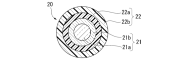
- FIG. 2 is a cross-sectional view taken along line II-II shown in FIG. 1;
- FIG. 4 is a diagram showing the results of a kink test for an optical fiber ribbon using optical fiber a.
- FIG. 4 is a diagram showing the results of a kink test on optical fiber ribbons using the optical fiber b.
- FIG. 4 is a diagram summarizing the maximum values of the amount of increase in transmission loss in a kink test;
- FIG. 10 is a diagram showing the results of a twisting test on an optical fiber ribbon using the optical fiber a.
- FIG. 10 is a diagram showing the results of a twisting test on the optical fiber ribbon using the optical fiber b.
- FIG. 4 is a diagram summarizing the amount of increase in transmission loss in a torsion test; It is a figure which shows the optical fiber tape cable core which concerns on 2nd Embodiment. It is a figure which shows the optical fiber tape cable core which concerns on 3rd Embodiment. It is a figure which shows the optical fiber tape cable core which concerns on a 1st modification. It is a figure which shows the optical fiber tape cable core which concerns on a 2nd modification.
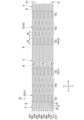
- the optical fiber ribbon 1A includes a plurality of optical fibers 20. As shown in FIG. A plurality of optical fibers 20 are arranged in a direction perpendicular to the longitudinal direction of each optical fiber 20 .
- the optical fiber tape core wire 1A further includes a plurality of connecting portions 10 that connect two adjacent optical fibers 20 among the plurality of optical fibers 20 .
- the optical fiber ribbon 1A includes 12 optical fibers 20 .
- Each optical fiber 20 may be referred to herein as a first fiber 201 to a twelfth fiber 212, respectively. However, the number of optical fibers 20 can be changed as appropriate.
- the X-axis direction is the longitudinal direction of the optical fiber ribbon 1A.
- the Y-axis direction is the direction in which the plurality of optical fibers 20 are arranged.
- the Z-axis direction is a direction orthogonal to both the X-axis direction and the Y-axis direction.
- the X-axis direction may be referred to as the longitudinal direction X
- the Y-axis direction may be referred to as the arrangement direction Y
- the Z-axis direction may be referred to as the perpendicular direction Z.
- One direction along the longitudinal direction X is called the +X direction or the right direction.
- the direction opposite to the +X direction is called the -X direction or leftward.
- the direction from the twelfth fiber 212 toward the first fiber 201 along the arrangement direction Y is called the +Y direction or upward.
- the direction opposite to the +Y direction is called the -Y direction or down.
- each optical fiber 20 has a waveguide 21 and a coating 22.
- the waveguide 21 is made of glass, for example.
- a waveguide 21 (glass portion) has a core 21a and a clad 21b.
- the clad 21b covers the core 21a.
- the covering portion 22 is made of resin or the like, and covers the glass portion 21 .
- a UV curable resin can be used.
- the covering portion 22 according to this embodiment has a primary layer 22a and a secondary layer 22b.
- the primary layer 22a covers the glass portion 21 (cladding 21b).
- the secondary layer 22b covers the primary layer 22a.
- each optical fiber 20 extends along the longitudinal direction X.
- the plurality of optical fibers 20 are arranged in the arrangement direction Y.
- a pitch P1 at which the plurality of optical fibers 20 are arranged in the arrangement direction Y is larger than the diameter (fiber diameter) R of each optical fiber 20 .
- a gap G is provided between two optical fibers 20 adjacent in the arrangement direction Y.
- the plurality of optical fibers 20 includes a pair of outermost fibers positioned on the outermost side in the arrangement direction Y and a plurality of intermediate fibers.
- a plurality of intermediate fibers are positioned in the arrangement direction Y between the pair of outermost fibers.
- the first fiber 201 and the twelfth fiber 212 correspond to the outermost fibers
- the second to eleventh fibers 202 to 211 correspond to the intermediate fibers.
- Each of the plurality of connecting parts 10 is formed in the gap G.
- the plurality of connecting portions 10 are arranged intermittently in the longitudinal direction X and the arrangement direction Y. As shown in FIG. In this specification, the phrase “intermittently arranged” includes both cases where the intervals between the plurality of connecting portions 10 are constant and cases where they are not constant.
- Each connecting portion 10 connects two optical fibers 20 adjacent to the gap G in which the connecting portion 10 is arranged. More specifically, each connecting portion 10 connects the covering portions 22 of two optical fibers 20 adjacent to the gap G in which the connecting portion 10 is arranged.
- optical fiber ribbon 1A in the optical fiber ribbon 1A according to this embodiment, two optical fibers 20 adjacent in the arrangement direction Y are intermittently connected to each other in the longitudinal direction X by a plurality of connecting portions 10 .
- the optical fiber tape core wire 1A is also called an intermittently fixed tape core wire 1A.
- Any material that can connect the coating portions 22 of the adjacent optical fibers 20 can be used as the connecting portion 10 .
- a UV curable resin may be used as the connecting portion 10 .
- the dimensions in the longitudinal direction X and the arrangement direction Y are substantially equal among the plurality of connecting portions 10 .
- the plurality of connecting portions 10 include a plurality of outermost connecting portions 10a that contact one of the pair of outermost fibers 201 and 212, and a plurality of intermediate connecting portions 10b that connect the intermediate fibers 202-211.
- each outermost connecting portion 10a connects the first fiber 201 and the second fiber 202 or the eleventh fiber 211 and the twelfth fiber 212 together.
- Each intermediate connecting portion 10b connects the second fiber 202 to the eleventh fiber 211. As shown in FIG.
- the optical fiber ribbon 1A has a plurality of high-density regions D and a plurality of low-density regions S.
- the plurality of high density regions D and the plurality of low density regions S are alternately arranged in the longitudinal direction X and are in contact with each other.
- the plurality of high-density regions D includes a first high-density region D1 and a second high-density region D2.
- the first high-density area D1 and the second high-density area D2 are arranged at different positions.
- the first high-density region D1 and the second high-density region D2 are in contact with the same low-density region S.
- the first high-density region D1 and the second high-density region D2 are arranged so as to sandwich one low-density region S in the longitudinal direction X. As shown in FIG.
- each high-density area D is formed in a substantially rectangular shape.
- each low-density area S is formed in a substantially rectangular shape.
- Each of the boundaries between the high density region D and the low density region S may be specifically referred to as a boundary B herein.
- each boundary B is a line segment parallel to the arrangement direction Y. As shown in FIG.
- Each boundary B is in contact with at least one connecting portion 10 (boundary connecting portion 10c).
- each high-density region D has six right end connecting portions 10R and six left end connecting portions 10L.
- the dimension LD in the longitudinal direction X is defined as follows. That is, the dimension LD is the distance in the longitudinal direction X between the right end of the right end connecting portion 10R included in the high density region D and the left end of the left end connecting portion 10L included in the high density region D. In the example of FIG. 1, the dimension in the longitudinal direction X is substantially constant at the dimension LD among the plurality of high-density regions D. In FIG.
- the dimension LS in the longitudinal direction X is defined as follows. That is, the dimension LS is between the right end of the right end connecting portion 10R included in the high density region D adjacent to the left of the low density region S, and the high density region adjacent to the right of the low density region S. D is the distance in the longitudinal direction X between the left end of the left end connecting portion 10L included in D.
- the dimension in the longitudinal direction X is substantially constant at the dimension LS among the plurality of low-density regions S. Note that the dimension LD may not be constant between the plurality of high-density regions D, and the dimension LS between the plurality of low-density regions S may not be constant.
- each high-density area D and the configuration of each low-density area S will be described below.
- each high-density region D at least two connecting portions 10 whose positions in the longitudinal direction X and the arrangement direction Y are different from each other among the plurality of connecting portions 10 are arranged.
- 28 connecting portions 10 are arranged in each high-density region D.
- the arrangement pattern of the 28 connecting portions 10 included in each high density region D is substantially the same among the plurality of high density regions D.
- the number of connecting portions 10 included in each high-density region D can be changed as appropriate, and the number of connecting portions 10 is not limited as long as the number is two or more.
- each high density region D has a plurality of boundary connecting portions 10c and non-boundary connecting portions 10d.
- the first high-density region D1 has a plurality of first boundary connecting portions 10c1
- the second high-density region D2 has a plurality of second boundary connecting portions 10c2.
- the plurality of first boundary connecting portions 10c1 and the plurality of second boundary connecting portions 10c2 are in contact with the same low density region S. As shown in FIG.
- the right end connecting portion 10R and the left end connecting portion 10L defined above are included in the plurality of boundary connecting portions 10c.
- all right end connecting portions 10R and left end connecting portions 10L are boundary connecting portions 10c.
- all boundary connecting portions 10c correspond to either the right end connecting portion 10R or the left end connecting portion 10L.
- the boundary connections 10c are not offset from each other in the longitudinal direction X.
- the high-density region D may have a boundary connecting portion 10c that does not correspond to either the right end connecting portion 10R or the left end connecting portion 10L.
- the boundary connections 10c may be offset from each other in the longitudinal direction X (see also FIG. 5).
- a plurality of boundary connecting portions 10c overlap each other in the arrangement direction Y. More specifically, in each high-density region D, all of the plurality of boundary connecting portions 10c contacting the same low-density region S overlap each other in the arrangement direction Y. As shown in FIG. For example, as shown in FIG. 1, all of the plurality of first boundary connecting portions 10c1 overlap each other in the arrangement direction Y. As shown in FIG. In other words, each high-density region D has a rectangular region in which a plurality of boundary connecting portions 10c overlap each other in the arrangement direction Y. As shown in FIG. This area is referred to herein as the "boundary area BA". As shown in FIG.
- all of the plurality of first boundary connecting portions 10c1 are included in the same boundary area BA.
- a side of the boundary area BA facing away from the center in the longitudinal direction X of the high-density area D is located on the boundary B.
- the boundary B extends along the side of the boundary area BA facing away from the center of the high-density area D in the longitudinal direction X.
- each high-density region D has first to fifth columns C1 to C5.
- the first to fifth columns C1 to C5 are arranged in this order from left to right.
- the pitch P2 at which the columns C1 to C5 are arranged is substantially constant.
- Each row C1-C5 is parallel to the arrangement direction Y.
- Each of the first column C1 and the fifth column C5 includes six boundary connecting portions 10c.
- the fifth row C5 of the first high-density area D1 includes six first boundary connecting portions 10c1.
- the first row C1 of the second high-density area D2 includes six second boundary connecting portions 10c2.
- Each of the second row C2 and the fourth row C4 includes five non-boundary connecting portions 10d.
- the third column C3 includes six non-boundary connecting portions 10d.
- the number of first boundary connecting portions 10c1 is greater than or equal to the number of non-boundary connecting portions 10d that overlap in the arrangement direction Y. In other words, the number of non-boundary connecting portions 10d that overlap in the arrangement direction Y is equal to or less than the number of first boundary connecting portions 10c1.
- the number of first boundary connecting portions 10c1 is six, and the number of non-boundary connecting portions 10d included in each column C2, C4 of each high-density region D is five, The number of non-boundary connecting portions 10d included in the third column C3 is six. Therefore, the number of non-boundary connecting portions 10d included in each column C2 to C4 of each high-density region D is six or less. In other words, among the columns C1 to C5, the first column C1 and the fifth column C5 have the largest number of connecting portions 10 included in the columns.
- each high-density area D all of the plurality of optical fibers 20 are in contact with one of the plurality of boundary connecting portions 10c. In other words, all of the plurality of optical fibers 20 are in contact with either of the plurality of connecting portions 10 included in the first row C1 or the fifth row C5.
- all of the plurality of optical fibers 20 are in contact with one of the plurality of first boundary connecting portions 10c1.
- all of the plurality of optical fibers 20 are in contact with one of the plurality of second boundary connecting portions 10c2.
- each high-density region D gaps G in which connecting portions 10 included in first, third, and fifth columns C1, C3, and C5 are located, and connecting portions included in second and fourth columns C2 and C4 It is shifted in the arrangement direction Y from the gap G in which the portion 10 is positioned.
- all of the plurality of optical fibers 20 are connected to each other by the connecting portion 10 .
- the layout pattern of the plurality of boundary connecting portions 10c contacting the left side of the low-density region S and the layout pattern of the plurality of boundary connecting portions 10c contacting the right side of the low-density region S are the same. .
- the plurality of boundary connecting portions 10c contacting a certain low-density area S are arranged symmetrically with respect to the low-density area S.
- the arrangement pattern of the plurality of second boundary connecting portions 10c2 is the same as the arrangement pattern of the plurality of first boundary connecting portions 10c1.
- the term “arrangement pattern of a plurality of first boundary connecting portions 10c1” means the position of each first boundary connecting portion 10c1 in the arrangement direction Y.
- the phrase “arrangement pattern of a plurality of second boundary connecting portions 10c2” means the position of each second boundary connecting portion 10c2 in the arrangement direction Y.
- each high-density region D includes a boundary connecting portion 10c connecting the first fiber 201 and the second fiber 202, and a boundary connecting portion connecting the eleventh fiber 211 and the twelfth fiber 212. 10c, are included. Further in other words, each high density region D includes a boundary connection portion 10c contacting the first fiber 201 and a boundary connection portion 10c contacting the twelfth fiber 212.
- the number density of the connecting portions 10 in each low-density region S is lower than the number density of the connecting portions 10 in each high-density region D.
- the “number density of the connecting portions 10 in the low-density region S” is a value obtained by dividing the number of connecting portions 10 included in the low-density region S by the area of the low-density region S.
- the “number density of the connecting portions 10 in the high-density region D” is a value obtained by dividing the number of connecting portions 10 included in the high-density region D by the area of the high-density region D.
- each low-density region S does not include the connecting portion 10 . That is, the number density of the connecting portions 10 in the low density region S is zero. However, the low-density region S may include the connecting portion 10 .
- the optical fiber tape core wire is made into a cable, etc.
- the optical fiber tape core wire is subjected to compressive stress along the longitudinal direction.
- the optical fiber ribbon has a low-density region with a small number of connecting portions
- the optical fiber bends in the low-density region due to the compressive stress, and abrupt bending (so-called kink) occurs.
- kink abrupt bending
- the optical fiber tape core wire may be subjected to a force that twists the optical fiber tape core wire around a rotation axis parallel to the longitudinal direction.
- the optical fiber may be slightly bent (so-called microbend) in the low-density area, resulting in an increase in transmission loss.
- the optical fiber ribbon 1A according to the present embodiment has a maximum increase in transmission loss of 1 dB or less occurring in light with a wavelength of 1550 nm propagating through the optical fiber 20 in a kink test (details will be described later). is configured to be In addition, the optical fiber ribbon 1A according to the present embodiment is configured so that the increase in transmission loss occurring in light with a wavelength of 1550 nm propagating through the optical fiber 20 in a twisting test (details will be described later) is 1 dB or less. ing. A specific configuration for setting the maximum increase in transmission loss in the kink test to 1 dB or less and the increase in transmission loss in the twist test to 1 dB or less will be described below using specific test examples. However, the optical fiber ribbon 1A does not have to be configured such that the increase in transmission loss in the twisting test is 1 dB or less.
- the "kink test” is a state in which the first high-density region D1 is fixed and a tension of 100 gf is applied to the entire optical fiber tape core wire, and the first high-density region D1 of the low-density region S is This test examines the amount of increase in transmission loss that occurs in light with a wavelength of 1550 nm propagating through the optical fiber 20 when the opposite edge (boundary B) is brought closer to the first high-density region D1 along the longitudinal direction X. .
- each of the plurality of optical fibers 20 constituting the optical fiber tape core wire was linearly extended in the longitudinal direction X, and the plurality of optical fibers 20 were arranged in the arrangement direction Y.
- the optical fiber ribbon was flattened so that the optical fiber ribbon would not be curled or twisted.
- the first high-density region D1 was fixed to a first fixture (not shown), and the second high-density region D2 was fixed to a second fixture (not shown).
- the second fixture was brought closer to the first fixture along the longitudinal direction X by a predetermined distance.
- a power meter connected to both ends of the optical fiber ribbon was used to measure the amount of increase in transmission loss caused by light with a wavelength of 1550 nm propagating through the optical fiber 20 .
- the state in which the second fixture is brought closer to the first fixture by a predetermined distance is compared with the initial state in which the second fixture is not brought closer to the first fixture. The amount of increase in transmission loss was measured.
- FIG. 3A is a graph summarizing the results of a kink test for an optical fiber ribbon using an optical fiber a whose primary layer 22a has a Young's modulus of 0.5 MPa or more.
- the "kink length" means the distance (movement distance from the initial state) by which the second fixture is brought closer to the first fixture.
- FIG. 3B is a graph summarizing the results of the kink test for the optical fiber ribbon using the optical fiber b whose Young's modulus of the primary layer 22a is less than 0.5 MPa.
- Tables 1 and 2 are tables summarizing each plotted point shown in FIGS. 3A and 3B.
- FIG. 3C is a graph summarizing the maximum amount of increase in transmission loss in each optical fiber ribbon. Note that FIG. 3C is a semi-logarithmic graph.
- the dimension LS of the low-density region S is set to a certain extent large, it is possible to realize an optical fiber ribbon that suppresses an increase in transmission loss due to kinks. More specifically, by setting the dimension LS in the longitudinal direction X of the low-density region S to 5.0 cm or more, the maximum value of the increase in transmission loss in the kink test is 1 dB regardless of the Young's modulus of the primary layer 22a. can be: Further, by setting the dimension LS in the longitudinal direction X of the low-density region S to 6.0 cm or more, the maximum value of the increase in transmission loss in the kink test is 0.1 dB or less regardless of the Young's modulus of the primary layer 22a. can do.
- Test Example 2 Twisting test
- a plurality of optical fiber ribbons were prepared under the same conditions as in Test Example 1. Then, a twisting test was performed on each optical fiber ribbon.
- the "twisting test” refers to a state in which the first high-density region D1 is fixed and a tension of 100 gf is applied to the entire optical fiber tape core wire, and the first high-density region D1 of the low-density region S and the is a test for examining the amount of increase in transmission loss that occurs in the light with a wavelength of 1550 nm propagating through the optical fiber 20 when the opposite edge (boundary B) is rotated around the rotation axis parallel to the longitudinal direction X.
- each of the plurality of optical fibers 20 constituting the optical fiber tape core wire was linearly extended in the longitudinal direction X, and the plurality of optical fibers 20 were arranged in the arrangement direction Y.
- the optical fiber ribbon was flattened so that the optical fiber ribbon would not be curled or twisted.
- the first high-density region D1 was fixed to a first fixture (not shown), and the second high-density region D2 was fixed to a second fixture (not shown).
- the second fixture was rotated by a predetermined angle around the rotation axis parallel to the longitudinal direction X with respect to the first fixture.
- a power meter connected to both ends of the optical fiber ribbon was used to measure the amount of increase in transmission loss caused by light with a wavelength of 1550 nm propagating through the optical fiber 20 .
- the state in which the second fixture is rotated by a predetermined angle with respect to the first fixture is compared with the initial state in which the second fixture is not rotated with respect to the first fixture.
- FIG. 4A is a graph summarizing the results of a twisting test for an optical fiber ribbon using an optical fiber a whose primary layer 22a has a Young's modulus of 0.5 MPa or more.
- the "number of twists" is a parameter corresponding to the rotation angle of the second fixture. That is, the number of twists is 0.5 when the second fixture is rotated by 180 degrees, and the number of twists is one when the second fixture is rotated by 360 degrees.
- FIG. 4B is a graph summarizing the results of the twisting test for the optical fiber ribbon using the optical fiber b whose primary layer 22a has a Young's modulus of less than 0.5 MPa. Tables 1 and 2 are tables summarizing each plotted point shown in FIGS. 4A and 4B.
- FIG. 4C is a graph summarizing the amount of increase in transmission loss when the number of twists is 4 for each optical fiber ribbon.
- the dimension LS of the low-density region S is set to a certain extent, it is possible to realize an optical fiber ribbon that suppresses an increase in transmission loss due to twisting.
- the maximum value of the increase in transmission loss in the kink test is set to 1 dB or less, and , the amount of increase in transmission loss in the twisting test can also be 1 dB or less.
- the optical fiber ribbon 1A has a plurality of high-density regions D in which many connecting portions 10 are arranged and few connecting portions 10 are arranged (especially in the example of FIG. 1, the connecting portions 10 are arranged and a plurality of low density regions S.
- the plurality of optical fibers 20 are connected to each other and integrated.
- the connecting portion 10 also serves to fix the pitch P1 at which two adjacent optical fibers 20 are arranged. Therefore, in each high-density area D, the pitch P1 of the optical fibers 20 can be stabilized.
- a fusion splicer is used when fusion-splicing an optical fiber tape core wire to another optical fiber tape core wire.
- the fuser has a holder for aligning the fiber optic ribbons.
- a plurality of grooves extending along the longitudinal direction X are formed in the holder.
- a plurality of optical fibers 20 included in the optical fiber ribbon are inserted one by one through the plurality of grooves for alignment.
- the pitch P1 is fixed by the connecting portion 10
- the optical fibers in the optical fiber tape core wire were arranged at the pitch P1.
- a fuser with grooves was used.
- the optical fiber ribbon 1A has a plurality of low-density regions S.
- the connecting portions 10 for fixing the pitch P1 at which the optical fibers 20 are arranged are not arranged or are few. Therefore, the user who uses the optical fiber ribbon 1A can widen the pitch P1 by pulling the optical fiber ribbon 1A in the arrangement direction Y in the low-density region S.
- a gap G is provided between two optical fibers 20 adjacent in the arrangement direction Y. As shown in FIG. Therefore, the user can narrow the pitch P1 by compressing the optical fiber ribbon 1A in the arrangement direction Y in the low-density region S.
- the pitch P1 is different from that of the optical fiber ribbon 1A. It becomes possible to use a fusion machine. Further, it is possible to fusion-splice the optical fiber tape core wire 1A to the optical fiber tape core wire having a pitch P1 different from that of the optical fiber tape core wire 1A.
- the optical fiber ribbon 1A includes a plurality of optical fibers 20 arranged in the arrangement direction Y perpendicular to the longitudinal direction X and two optical fibers adjacent in the arrangement direction Y. and a plurality of connecting portions 10 formed between the two optical fibers 20 and connecting the two optical fibers 20.
- the plurality of connecting portions 10 are intermittently arranged in the longitudinal direction X and the arrangement direction Y, and the optical fibers
- the fiber ribbon 1A has a first high-density region D1 and a low-density region S that are adjacent in the longitudinal direction X.
- the longitudinal direction X and the arrangement direction Y At least two connecting portions 10 whose positions are different from each other are arranged, and the number density of the connecting portions 10 in the low density region S is lower than the number density of the connecting portions 10 in the first high density region D1, and in the kink test, light
- the maximum value of the increase in transmission loss that occurs in light with a wavelength of 1550 nm propagating through the fiber 20 is 1 dB or less.
- the maximum value of the increase in transmission loss that occurs in light with a wavelength of 1550 nm propagating through the optical fiber 20 is 1 dB or less.
- the pitch P1 at which the plurality of optical fibers 20 are arranged in the arrangement direction Y is larger than the diameter R of each of the plurality of optical fibers 20 .
- This configuration makes it possible to use a fusion splicer having a pitch P1 different from that of the optical fiber ribbon 1A when fusion splicing the optical fiber ribbon 1A. Further, it is possible to fusion-splice the optical fiber tape core wire 1A to the optical fiber tape core wire having a pitch P1 different from that of the optical fiber tape core wire 1A.
- the outermost fibers 201 and 212 are more likely to be misaligned or bent in the grooves of the fusion splicer than the intermediate fibers 202 to 211 when the optical fiber ribbon 1A is set in the fusion splicer.
- the plurality of optical fibers 20 include a pair of outermost fibers 201 and 212 located on the outermost side in the arrangement direction Y, and a pair of outermost fibers 201 and 212 in the arrangement direction Y.
- the first boundary connection portion 10c1 connects the outermost fibers 201, 212 and the intermediate fibers 202, 211.
- the movement of the outermost fibers 201 and 212 at the boundary B between the high density region D and the low density region S can be made difficult. Therefore, when the optical fiber ribbon 1A is set in the grooves of the fusion splicer, it is possible to prevent the outermost fibers 201 and 212 from being misaligned or bent with respect to the grooves.
- the plurality of connecting portions 10 include a plurality of first boundary connecting portions 10c1 positioned at the boundary B between the first high-density region D1 and the low-density region S and overlapping each other in the arrangement direction Y. , all of the plurality of optical fibers 20 are in contact with one of the plurality of first boundary connection portions 10c1. This makes it difficult for all the optical fibers 20 to move at the boundary B between the high-density region D and the low-density region S. FIG. Therefore, the operation of setting the optical fiber ribbon 1A in the fusion splicer can be made easier.
- the number of first boundary connecting portions 10c1 is equal to or greater than the number of non-boundary connecting portions 10d that overlap in the arrangement direction Y.
- the second high-density region D2 is arranged at a position different from the first high-density region D1 in the longitudinal direction X and is arranged to contact the low-density region S in the longitudinal direction X.
- the region D2 at least two connecting portions 10 whose positions in the longitudinal direction X and the arrangement direction Y are different from each other among the plurality of connecting portions 10 are arranged, and the number density of the connecting portions 10 in the second high-density region D2 is low.
- the number density of the connecting portions 10 is higher than the number density of the connecting portions 10 in the density region S, and the plurality of connecting portions 10 are located on the boundary B between the first high-density region D1 and the low-density region S and a plurality of overlapping first boundary connecting portions 10c1; a plurality of second boundary connecting portions 10c2 positioned at the boundary B between the second high-density region D2 and the low-density region S and overlapping each other in the arrangement direction Y; , and the arrangement pattern of the plurality of second boundary connecting portions 10c2 is the same as the arrangement pattern of the plurality of first boundary connecting portions 10c1.
- the optical fiber ribbon 1A when the optical fiber ribbon 1A is set in the fusion splicer, the movement of the optical fiber 20 at the left end of the low density region S and the movement of the optical fiber 20 at the right end of the low density region S are easily interlocked. Become. In other words, the movement of the optical fiber 20 at the left end of the fusion splicer and the movement of the optical fiber 20 at the right end of the fusion splicer are likely to be interlocked. Therefore, the operation of setting the optical fiber ribbon 1A in the fusion splicer can be made easier.
- the fact that the number of connecting portions 10 is different between the high-density region D and the low-density region S also has an effect on the distinguishability between the high-density region D and the low-density region S. Since the number of connecting portions 10 is large in the high-density area D, the high-density area D can be easily identified by scattering of external light. On the other hand, in the low-density area S, by pulling the optical fiber ribbon 1A in the arrangement direction Y, the pitch P1 can be widened, and the low-density area S can be easily identified. Also, by coloring the resin of the connecting portion 10 or marking it, the high-density area D and the low-density area S can be distinguished more effectively.
- the inventors of the present application have considered that the longer the dimension LS of the low-density region S, the easier it is for the external force to concentrate on the boundary connecting portion 10c. More specifically, it was considered that the magnitude of the external force concentrated on the boundary connecting portion 10c is proportional to the dimension LS. In other words, it is considered that the longer the dimension LS, the more likely the boundary connecting portion 10c is cracked.
- the dimension LS of the low-density region S is set to a certain upper limit value or less so that the magnitude of the external force concentrated on the boundary connecting portion 10c does not exceed 3.0 gf. It is considered necessary to It should be noted that the “strength of the connecting portion 10 ” is the maximum value of the external force with which the connecting portion 10 is held without cracking when an external force is applied to the connecting portion 10 .
- the inventors of the present application conducted the following test in order to investigate the upper limit of the dimension LS that does not cause cracks in each connecting portion 10. That is, when a predetermined external force is applied to the optical fiber ribbon 1A having the dimension LS of the low-density region S of about 30 mm, it was tested whether or not the connecting portion 10 (boundary connecting portion 10c) cracked. . More specifically, the optical fiber ribbon 1A having 200 optical fibers 20 was subjected to an ironing test with a tension of 130 kgf, a mandrel diameter of 250 mm, and a bending angle of 90°. I checked to see if it was there.
- the inventors of the present application considered that the boundary connecting portion 10c is more likely to crack than the non-boundary connecting portion 10d and that the strength of the connecting portion 10 varies. , it is desirable that the following formula (2) holds. F[gf] ⁇ A[gf]-3S[gf] (2) However, A is the average value of the strength (tear strength) of the connecting portion 10 and S is the standard deviation of the strength of the connecting portion 10 .
- the upper limit of the dimension LS may be determined as follows. That is, dimension LS may be 100 mm or less.
- the dimension in the longitudinal direction X of the fusion splicer is generally about 200 mm. Therefore, considering the case where two optical fiber ribbons 1A are fusion-spliced in their low-density regions S, the total dimension LS of both low-density regions S is preferably 200 mm or less. This is because if the total of the two dimensions LS exceeds 200 mm, at least one of the low-density regions S protrudes outside the fusion splicer, making the work of setting the optical fiber ribbon 1A in the fusion splicer complicated.
- the total of the two dimensions LS can be set to 200 mm or less. This makes it easier to set the two optical fiber ribbons 1A in the fusion splicer.
- the strength of the connecting portion 10 is preferably within the range of 1.5 to 21.0 gf. If this is applied to the present embodiment, it is desirable that the following formula (4) holds, considering variations in strength of the connecting portion 10 as well. 1.5 [gf] ⁇ A-3S [gf] ⁇ A + 3S [gf] ⁇ 21.0 [gf] (4)
- An optical fiber ribbon 1B according to the present embodiment shown in FIG. 5 is different from the optical fiber ribbon 1A according to the first embodiment in the dimensions and positional relationship of each connecting portion 10 .
- the dimension (first dimension) d1 in the longitudinal direction X of each outermost connecting portion 10a is equal to the dimension in the longitudinal direction X of each intermediate connecting portion 10b. (Second dimension) larger than d2.
- the arrangement interval I1 (first arrangement interval) in the longitudinal direction X of the outermost connecting portions 10a is longer than the arrangement interval I2 (second arrangement interval) in the longitudinal direction X of the intermediate connecting portions 10b. small.
- the outermost fibers 201 and 212 can be more strongly connected to the intermediate fibers 202 and 211 than, for example, when the dimension d1 and the dimension d2 are equal.
- the outermost fibers 201 and 212 can be more strongly connected to the intermediate fibers 202 and 211 than, for example, when the arrangement interval I1 and the arrangement interval I2 are equal. Therefore, when the optical fiber ribbon 1B is set in the groove of the fusion splicer, it is possible to further reduce the possibility that the outermost fibers 201 and 212 are misaligned or bent with respect to the groove.
- the dimension d1 in the longitudinal direction X of the outermost connecting portion 10a is larger than the dimension d2 in the longitudinal direction X of the intermediate connecting portion 10b.
- the arrangement interval I1 in the longitudinal direction X of the outermost connecting portions 10a is smaller than the arrangement interval I2 in the longitudinal direction X of the intermediate connecting portions 10b.
- An optical fiber ribbon 1C according to the present embodiment shown in FIG. 6 is different from the optical fiber ribbon 1A according to the first embodiment in the dimensions and positional relationship of each connecting portion 10. As shown in FIG.
- the dimension (third dimension) d3 in the longitudinal direction X of each boundary connecting portion 10c is equal to the dimension in the longitudinal direction X of each non-boundary connecting portion 10d. (Fourth dimension) greater than d4.
- the dimension d3 in the longitudinal direction X of the first boundary connecting portion 10c1 is larger than the dimension d4 in the longitudinal direction X of the non-boundary connecting portion 10d.
- the rigidity of the optical fiber ribbon 1C can be increased at the boundary B between the high-density region D and the low-density region S compared to the case where the dimensions d3 and d4 are equal, for example. Therefore, the operation of setting the optical fiber ribbon 1C in the fusion splicer can be made easier.
- the dimension d3 in the longitudinal direction X of the first boundary connecting portion 10c1 is larger than the dimension d4 in the longitudinal direction X of the non-boundary connecting portion 10d. .
- This configuration makes it easier to set the optical fiber ribbon 1C in the fusion splicer.
- the number of non-boundary connecting portions 10d included in each column C2 to C4 of each high-density region D was less than or equal to the number (6) of the first boundary connecting portions 10c1.
- the configuration of the connecting portion 10d is not limited to this.
- the number of non-boundary connecting portions 10d included in each column C2 to C4 of each high-density region D may be less than the number of first boundary connecting portions 10c1.
- the number of non-boundary connecting portions 10d included in the third row C3 may be less than the number of first boundary connecting portions 10c1.
- the boundary connecting portions 10c may be displaced from each other in the longitudinal direction X like the optical fiber ribbon 1E shown in FIG.
- the high-density area D may have a boundary connecting portion 10c that does not correspond to either the right end connecting portion 10R or the left end connecting portion 10L.
- each high-density area D has three right end connecting portions 10R and three left end connecting portions 10L.
- each high-density area D has a boundary area BA where a plurality of boundary connecting portions 10c overlap each other in the arrangement direction Y, as in the above-described embodiment.
- the boundary B extends along the sides of the boundary area BA. At this time, a lower limit value and an upper limit value may be set for the dimension LS as in the above embodiment. With this configuration, the same effects as those of the above-described embodiment can be obtained.
- the optical fiber ribbons 1A-1C had a plurality of high-density regions D and a plurality of low-density regions S, but the configuration of the optical fiber ribbons 1A-1C is limited to this. can't
- the optical fiber ribbons 1A-1C may have only one high density region D and only one low density region S.
- the arrangement pattern of the plurality of connecting portions 10 included in each high-density region D does not have to be the same among the high-density regions D.
- the arrangement pattern of the connecting portions 10 included in each low-density region S may not be the same among the low-density regions S.
- each of the regions D and S does not have to be substantially rectangular.
- each boundary B does not have to be parallel to the arrangement direction Y.
- the fusion splicer (holder) generally has a rectangular shape, a configuration in which the boundary B is parallel to the arrangement direction Y is preferable.
- each high-density region D may not form columns C1 to C5.
- the plurality of connecting portions 10 may be randomly arranged.
- the plurality of connecting portions 10 may be randomly arranged in each low-density region S.
- the gap G may not be provided between the two optical fibers 20 adjacent in the arrangement direction Y.
- two adjacent optical fibers 20 may be in contact with each other. Even with such a configuration, two adjacent optical fibers 20 can be intermittently connected by the connecting portion 10 .
- Optical fiber ribbon 10 For Coupling section 10a... Outermost coupling section 10b... Intermediate coupling section 10c1... First boundary coupling section 10c2... Second boundary coupling section 10d... Non-boundary coupling section 20... Optical fiber 201... First fiber (outermost fiber) 202 to 211... Second fiber to 11th fiber (intermediate fiber) 212... Twelfth fiber (outermost fiber) G... Gap D1... First high density area D2 ... Second high-density area S... Low-density area B... Boundary P1... Pitch R... Fiber diameter (diameter) d1 to d4... Dimensions I1, I2... Arrangement interval X... Longitudinal direction Y... Arrangement direction
Landscapes
- Physics & Mathematics (AREA)
- General Physics & Mathematics (AREA)
- Optics & Photonics (AREA)
- Mechanical Coupling Of Light Guides (AREA)
- Optical Fibers, Optical Fiber Cores, And Optical Fiber Bundles (AREA)
Priority Applications (7)
| Application Number | Priority Date | Filing Date | Title |
|---|---|---|---|
| EP22878435.1A EP4414762A4 (en) | 2021-10-04 | 2022-09-30 | FIBER OPTIC RIBBON |
| KR1020247005913A KR20240027159A (ko) | 2021-10-04 | 2022-09-30 | 광섬유 테이프 심선 |
| AU2022360567A AU2022360567B2 (en) | 2021-10-04 | 2022-09-30 | Optical fiber ribbon |
| JP2023552847A JP7692491B2 (ja) | 2021-10-04 | 2022-09-30 | 光ファイバテープ心線 |
| CN202280056210.5A CN117813535A (zh) | 2021-10-04 | 2022-09-30 | 光纤带芯线 |
| CA3231949A CA3231949A1 (en) | 2021-10-04 | 2022-09-30 | Optical fiber ribbon |
| US18/697,954 US20240418952A1 (en) | 2021-10-04 | 2022-09-30 | Optical fiber ribbon |
Applications Claiming Priority (2)
| Application Number | Priority Date | Filing Date | Title |
|---|---|---|---|
| US202163251692P | 2021-10-04 | 2021-10-04 | |
| US63/251,692 | 2021-10-04 |
Publications (1)
| Publication Number | Publication Date |
|---|---|
| WO2023058566A1 true WO2023058566A1 (ja) | 2023-04-13 |
Family
ID=85803420
Family Applications (1)
| Application Number | Title | Priority Date | Filing Date |
|---|---|---|---|
| PCT/JP2022/036649 Ceased WO2023058566A1 (ja) | 2021-10-04 | 2022-09-30 | 光ファイバテープ心線 |
Country Status (9)
| Country | Link |
|---|---|
| US (1) | US20240418952A1 (https=) |
| EP (1) | EP4414762A4 (https=) |
| JP (1) | JP7692491B2 (https=) |
| KR (1) | KR20240027159A (https=) |
| CN (1) | CN117813535A (https=) |
| AU (1) | AU2022360567B2 (https=) |
| CA (1) | CA3231949A1 (https=) |
| TW (1) | TWI859588B (https=) |
| WO (1) | WO2023058566A1 (https=) |
Cited By (1)
| Publication number | Priority date | Publication date | Assignee | Title |
|---|---|---|---|---|
| WO2025080852A1 (en) * | 2023-10-10 | 2025-04-17 | Belden Inc. | Intermittently bonded optical fiber ribbon having a repeating pattern of bond length and gap lengths configured to enhance flexibility and robustness of the optical fiber ribbon |
Families Citing this family (1)
| Publication number | Priority date | Publication date | Assignee | Title |
|---|---|---|---|---|
| KR20260000688A (ko) * | 2024-06-26 | 2026-01-05 | 엘에스전선 주식회사 | 롤러블 광섬유 리본 |
Citations (8)
| Publication number | Priority date | Publication date | Assignee | Title |
|---|---|---|---|---|
| JP2011169937A (ja) * | 2010-02-16 | 2011-09-01 | Furukawa Electric Co Ltd:The | 光ファイバテープ心線及び光ファイバケーブル |
| JP2012234122A (ja) * | 2011-05-09 | 2012-11-29 | Fujikura Ltd | 光ユニット |
| JP2013182157A (ja) | 2012-03-02 | 2013-09-12 | Fujikura Ltd | 光ファイバテープ心線及びその光ファイバテープ心線を収納した光ファイバケーブル |
| JP2014095560A (ja) * | 2012-11-07 | 2014-05-22 | Swcc Showa Cable Systems Co Ltd | 間欠型光ファイバテープ心線の検査方法、製造方法および検査装置 |
| JP2014215493A (ja) * | 2013-04-26 | 2014-11-17 | 日本電信電話株式会社 | 間欠接着型光ファイバテープ |
| WO2019011417A1 (en) * | 2017-07-11 | 2019-01-17 | Prysmian S.P.A. | OPTICAL FIBER TAPE AND METHOD FOR PRODUCING THE SAME |
| JP2020181048A (ja) * | 2019-04-24 | 2020-11-05 | 古河電気工業株式会社 | 光ファイバテープ心線、光ファイバケーブル |
| JP2021043363A (ja) | 2019-09-12 | 2021-03-18 | 株式会社フジクラ | 光ファイバ整列方法、光ファイバ融着方法、コネクタ付き光ファイバテープの製造方法及び間欠連結型の光ファイバテープ |
Family Cites Families (8)
| Publication number | Priority date | Publication date | Assignee | Title |
|---|---|---|---|---|
| JP2007101955A (ja) | 2005-10-05 | 2007-04-19 | Nippon Telegr & Teleph Corp <Ntt> | 光ファイバユニット及び光ファイバケーブル |
| JP5697011B2 (ja) | 2010-02-16 | 2015-04-08 | 古河電気工業株式会社 | 光ファイバケーブル、及び光ファイバケーブルの形成方法 |
| JP2014016530A (ja) | 2012-07-10 | 2014-01-30 | Sumitomo Electric Ind Ltd | 光ファイバテープ心線ユニットおよび光ファイバケーブル |
| JP6657976B2 (ja) * | 2016-01-13 | 2020-03-04 | 住友電気工業株式会社 | 間欠連結型光ファイバテープ心線および光ケーブル |
| JP6952728B2 (ja) * | 2019-02-14 | 2021-10-20 | 昭和電線ケーブルシステム株式会社 | 間欠接着型光ファイバテープ心線 |
| EP4177651A4 (en) | 2020-07-01 | 2024-07-10 | Fujikura Ltd. | OPTICAL FIBER UNIT AND MANUFACTURING METHOD THEREFOR |
| JP7479225B2 (ja) | 2020-07-07 | 2024-05-08 | 古河電気工業株式会社 | 光ファイバテープ心線、光ファイバケーブル |
| US11460652B2 (en) | 2020-12-22 | 2022-10-04 | Prysmian S.P.A. | Optical-fiber ribbon with adhesive-free gaps |
-
2022
- 2022-09-30 WO PCT/JP2022/036649 patent/WO2023058566A1/ja not_active Ceased
- 2022-09-30 US US18/697,954 patent/US20240418952A1/en active Pending
- 2022-09-30 CA CA3231949A patent/CA3231949A1/en active Pending
- 2022-09-30 KR KR1020247005913A patent/KR20240027159A/ko not_active Ceased
- 2022-09-30 AU AU2022360567A patent/AU2022360567B2/en active Active
- 2022-09-30 TW TW111137259A patent/TWI859588B/zh active
- 2022-09-30 JP JP2023552847A patent/JP7692491B2/ja active Active
- 2022-09-30 EP EP22878435.1A patent/EP4414762A4/en active Pending
- 2022-09-30 CN CN202280056210.5A patent/CN117813535A/zh active Pending
Patent Citations (8)
| Publication number | Priority date | Publication date | Assignee | Title |
|---|---|---|---|---|
| JP2011169937A (ja) * | 2010-02-16 | 2011-09-01 | Furukawa Electric Co Ltd:The | 光ファイバテープ心線及び光ファイバケーブル |
| JP2012234122A (ja) * | 2011-05-09 | 2012-11-29 | Fujikura Ltd | 光ユニット |
| JP2013182157A (ja) | 2012-03-02 | 2013-09-12 | Fujikura Ltd | 光ファイバテープ心線及びその光ファイバテープ心線を収納した光ファイバケーブル |
| JP2014095560A (ja) * | 2012-11-07 | 2014-05-22 | Swcc Showa Cable Systems Co Ltd | 間欠型光ファイバテープ心線の検査方法、製造方法および検査装置 |
| JP2014215493A (ja) * | 2013-04-26 | 2014-11-17 | 日本電信電話株式会社 | 間欠接着型光ファイバテープ |
| WO2019011417A1 (en) * | 2017-07-11 | 2019-01-17 | Prysmian S.P.A. | OPTICAL FIBER TAPE AND METHOD FOR PRODUCING THE SAME |
| JP2020181048A (ja) * | 2019-04-24 | 2020-11-05 | 古河電気工業株式会社 | 光ファイバテープ心線、光ファイバケーブル |
| JP2021043363A (ja) | 2019-09-12 | 2021-03-18 | 株式会社フジクラ | 光ファイバ整列方法、光ファイバ融着方法、コネクタ付き光ファイバテープの製造方法及び間欠連結型の光ファイバテープ |
Non-Patent Citations (1)
| Title |
|---|
| See also references of EP4414762A4 |
Cited By (1)
| Publication number | Priority date | Publication date | Assignee | Title |
|---|---|---|---|---|
| WO2025080852A1 (en) * | 2023-10-10 | 2025-04-17 | Belden Inc. | Intermittently bonded optical fiber ribbon having a repeating pattern of bond length and gap lengths configured to enhance flexibility and robustness of the optical fiber ribbon |
Also Published As
| Publication number | Publication date |
|---|---|
| CN117813535A (zh) | 2024-04-02 |
| TWI859588B (zh) | 2024-10-21 |
| EP4414762A4 (en) | 2025-09-10 |
| TW202321744A (zh) | 2023-06-01 |
| KR20240027159A (ko) | 2024-02-29 |
| AU2022360567B2 (en) | 2025-12-11 |
| JP7692491B2 (ja) | 2025-06-13 |
| JPWO2023058566A1 (https=) | 2023-04-13 |
| EP4414762A1 (en) | 2024-08-14 |
| AU2022360567A1 (en) | 2024-04-11 |
| CA3231949A1 (en) | 2023-04-13 |
| US20240418952A1 (en) | 2024-12-19 |
Similar Documents
| Publication | Publication Date | Title |
|---|---|---|
| CN102681119B (zh) | 光纤缆线以及光纤带 | |
| JP4619424B2 (ja) | 光ファイバケーブル | |
| US8295667B2 (en) | Hole arranged photonic crystal fiber for low loss, tight fiber bending applications | |
| US9069116B2 (en) | Fan-in/fan-out device for multicore fiber | |
| JP5235125B2 (ja) | 光ファイバテープ及び光ファイバケーブル | |
| JP7692491B2 (ja) | 光ファイバテープ心線 | |
| CN116368105B (zh) | 多芯光纤 | |
| CN111801612B (zh) | 光学连接部件 | |
| JP5871423B2 (ja) | 光ファイバモジュール | |
| JP2016148709A (ja) | 光ファイバユニットおよび光ケーブル | |
| EP3943992B1 (en) | Intermittent connection-type optical fiber tape core, optical fiber cable and connector-equipped optical fiber cord | |
| US20110176767A1 (en) | Optical fiber connection structure | |
| WO2024095531A1 (ja) | マルチコア光ファイバの調心装置、マルチコア光ファイバリボンの製造装置、マルチコア光ファイバユニットの製造装置、マルチコア光ファイバの調心方法、マルチコア光ファイバリボンの製造方法、マルチコア光ファイバユニットの製造方法、マルチコア光ファイバリボンの検査装置、及びマルチコア光ファイバリボンの検査方法 | |
| US12436351B2 (en) | Optical fiber ribbon, optical fiber connection component, and method for manufacturing optical fiber connection component | |
| CA3224169C (en) | Optical fiber ribbon | |
| AU2022310612B2 (en) | Optical fiber ribbon | |
| JP2022124194A (ja) | 光コネクタの製造方法および光コネクタ | |
| WO2026022974A1 (ja) | 光ケーブル、および、光ケーブルの製造方法 | |
| JP2026054823A (ja) | 光ファイバテープ心線、光ファイバテープ心線の製造方法、および、光ファイバテープ心線の製造装置 | |
| WO2025075063A1 (ja) | 光コネクタ、光接続アセンブリ、光導波路部材、および光コネクタの製造方法 | |
| WO2023127528A1 (ja) | 光ファイバ集合体及び光ケーブル | |
| JP2019066769A (ja) | 光ファイバの融着接続方法、光ファイバの融着接続構造、及び光配線部材 | |
| JP2004004388A (ja) | 光配線板装置 |
Legal Events
| Date | Code | Title | Description |
|---|---|---|---|
| 121 | Ep: the epo has been informed by wipo that ep was designated in this application |
Ref document number: 22878435 Country of ref document: EP Kind code of ref document: A1 |
|
| WWE | Wipo information: entry into national phase |
Ref document number: 2023552847 Country of ref document: JP |
|
| WWE | Wipo information: entry into national phase |
Ref document number: 202280056210.5 Country of ref document: CN |
|
| ENP | Entry into the national phase |
Ref document number: 20247005913 Country of ref document: KR Kind code of ref document: A |
|
| WWE | Wipo information: entry into national phase |
Ref document number: 1020247005913 Country of ref document: KR |
|
| WWE | Wipo information: entry into national phase |
Ref document number: 3231949 Country of ref document: CA |
|
| WWE | Wipo information: entry into national phase |
Ref document number: 202417022448 Country of ref document: IN Ref document number: 2022360567 Country of ref document: AU Ref document number: AU2022360567 Country of ref document: AU |
|
| WWE | Wipo information: entry into national phase |
Ref document number: 18697954 Country of ref document: US |
|
| ENP | Entry into the national phase |
Ref document number: 2022360567 Country of ref document: AU Date of ref document: 20220930 Kind code of ref document: A |
|
| WWE | Wipo information: entry into national phase |
Ref document number: 2022878435 Country of ref document: EP |
|
| NENP | Non-entry into the national phase |
Ref country code: DE |
|
| ENP | Entry into the national phase |
Ref document number: 2022878435 Country of ref document: EP Effective date: 20240506 |
|
| WWR | Wipo information: refused in national office |
Ref document number: 1020247005913 Country of ref document: KR |