WO2023054591A1 - 紫外線、可視光線および/または赤外線を拡散反射する物品およびその製造方法 - Google Patents
紫外線、可視光線および/または赤外線を拡散反射する物品およびその製造方法 Download PDFInfo
- Publication number
- WO2023054591A1 WO2023054591A1 PCT/JP2022/036457 JP2022036457W WO2023054591A1 WO 2023054591 A1 WO2023054591 A1 WO 2023054591A1 JP 2022036457 W JP2022036457 W JP 2022036457W WO 2023054591 A1 WO2023054591 A1 WO 2023054591A1
- Authority
- WO
- WIPO (PCT)
- Prior art keywords
- solvent
- article
- thermoplastic polymer
- layer
- contact
- Prior art date
Links
- 238000004519 manufacturing process Methods 0.000 title claims abstract description 13
- 239000002904 solvent Substances 0.000 claims abstract description 89
- 229920001169 thermoplastic Polymers 0.000 claims abstract description 76
- 238000001035 drying Methods 0.000 claims abstract description 25
- 238000009835 boiling Methods 0.000 claims abstract description 13
- 238000001816 cooling Methods 0.000 claims abstract description 5
- -1 polyethylene Polymers 0.000 claims description 29
- 238000000034 method Methods 0.000 claims description 26
- 239000000203 mixture Substances 0.000 claims description 25
- 239000004743 Polypropylene Substances 0.000 claims description 20
- 238000002425 crystallisation Methods 0.000 claims description 20
- 230000008025 crystallization Effects 0.000 claims description 20
- 229920001155 polypropylene Polymers 0.000 claims description 20
- 239000002033 PVDF binder Substances 0.000 claims description 14
- 229920002981 polyvinylidene fluoride Polymers 0.000 claims description 14
- 229920001400 block copolymer Polymers 0.000 claims description 13
- 239000004698 Polyethylene Substances 0.000 claims description 9
- 229920000573 polyethylene Polymers 0.000 claims description 9
- 239000004952 Polyamide Substances 0.000 claims description 7
- 229920002647 polyamide Polymers 0.000 claims description 7
- 239000000654 additive Substances 0.000 claims description 6
- 239000011231 conductive filler Substances 0.000 claims description 6
- 229920001707 polybutylene terephthalate Polymers 0.000 claims description 6
- 229920000139 polyethylene terephthalate Polymers 0.000 claims description 6
- 239000005020 polyethylene terephthalate Substances 0.000 claims description 6
- 229920006324 polyoxymethylene Polymers 0.000 claims description 6
- 230000005855 radiation Effects 0.000 claims description 6
- 239000000945 filler Substances 0.000 claims description 5
- 229920001519 homopolymer Polymers 0.000 claims description 5
- 229920006135 semi-crystalline thermoplastic polymer Polymers 0.000 claims description 4
- 229930182556 Polyacetal Natural products 0.000 claims description 3
- 229920010524 Syndiotactic polystyrene Polymers 0.000 claims description 3
- 239000003963 antioxidant agent Substances 0.000 claims description 3
- 239000002216 antistatic agent Substances 0.000 claims description 3
- 239000003086 colorant Substances 0.000 claims description 3
- 239000002270 dispersing agent Substances 0.000 claims description 3
- 239000003063 flame retardant Substances 0.000 claims description 3
- 239000000314 lubricant Substances 0.000 claims description 3
- 239000002667 nucleating agent Substances 0.000 claims description 3
- 239000004626 polylactic acid Substances 0.000 claims description 3
- 239000012744 reinforcing agent Substances 0.000 claims description 3
- 229920006126 semicrystalline polymer Polymers 0.000 claims description 3
- 239000003381 stabilizer Substances 0.000 claims description 3
- 239000006096 absorbing agent Substances 0.000 claims description 2
- 239000004014 plasticizer Substances 0.000 claims 1
- 239000010410 layer Substances 0.000 description 108
- 239000000463 material Substances 0.000 description 14
- 229920000642 polymer Polymers 0.000 description 12
- 238000001125 extrusion Methods 0.000 description 11
- VGGSQFUCUMXWEO-UHFFFAOYSA-N Ethene Chemical compound C=C VGGSQFUCUMXWEO-UHFFFAOYSA-N 0.000 description 10
- 239000005977 Ethylene Substances 0.000 description 10
- IAZDPXIOMUYVGZ-UHFFFAOYSA-N Dimethylsulphoxide Chemical compound CS(C)=O IAZDPXIOMUYVGZ-UHFFFAOYSA-N 0.000 description 9
- QQONPFPTGQHPMA-UHFFFAOYSA-N propylene Natural products CC=C QQONPFPTGQHPMA-UHFFFAOYSA-N 0.000 description 9
- 125000004805 propylene group Chemical group [H]C([H])([H])C([H])([*:1])C([H])([H])[*:2] 0.000 description 9
- CTQNGGLPUBDAKN-UHFFFAOYSA-N O-Xylene Chemical compound CC1=CC=CC=C1C CTQNGGLPUBDAKN-UHFFFAOYSA-N 0.000 description 8
- 230000000052 comparative effect Effects 0.000 description 8
- 239000008096 xylene Substances 0.000 description 8
- 229920011250 Polypropylene Block Copolymer Polymers 0.000 description 7
- NNBZCPXTIHJBJL-UHFFFAOYSA-N decalin Chemical compound C1CCCC2CCCCC21 NNBZCPXTIHJBJL-UHFFFAOYSA-N 0.000 description 5
- YXFVVABEGXRONW-UHFFFAOYSA-N Toluene Chemical group CC1=CC=CC=C1 YXFVVABEGXRONW-UHFFFAOYSA-N 0.000 description 4
- 239000011324 bead Substances 0.000 description 4
- 229920001577 copolymer Polymers 0.000 description 4
- 238000005259 measurement Methods 0.000 description 4
- 229920005629 polypropylene homopolymer Polymers 0.000 description 4
- RFFLAFLAYFXFSW-UHFFFAOYSA-N 1,2-dichlorobenzene Chemical compound ClC1=CC=CC=C1Cl RFFLAFLAYFXFSW-UHFFFAOYSA-N 0.000 description 3
- QTBSBXVTEAMEQO-UHFFFAOYSA-N Acetic acid Chemical compound CC(O)=O QTBSBXVTEAMEQO-UHFFFAOYSA-N 0.000 description 3
- CSCPPACGZOOCGX-UHFFFAOYSA-N Acetone Chemical compound CC(C)=O CSCPPACGZOOCGX-UHFFFAOYSA-N 0.000 description 3
- WEVYAHXRMPXWCK-UHFFFAOYSA-N Acetonitrile Chemical compound CC#N WEVYAHXRMPXWCK-UHFFFAOYSA-N 0.000 description 3
- RTZKZFJDLAIYFH-UHFFFAOYSA-N Diethyl ether Chemical compound CCOCC RTZKZFJDLAIYFH-UHFFFAOYSA-N 0.000 description 3
- XEKOWRVHYACXOJ-UHFFFAOYSA-N Ethyl acetate Chemical compound CCOC(C)=O XEKOWRVHYACXOJ-UHFFFAOYSA-N 0.000 description 3
- IMNFDUFMRHMDMM-UHFFFAOYSA-N N-Heptane Chemical compound CCCCCCC IMNFDUFMRHMDMM-UHFFFAOYSA-N 0.000 description 3
- 239000011248 coating agent Substances 0.000 description 3
- 238000000576 coating method Methods 0.000 description 3
- MTHSVFCYNBDYFN-UHFFFAOYSA-N diethylene glycol Chemical compound OCCOCCO MTHSVFCYNBDYFN-UHFFFAOYSA-N 0.000 description 3
- 238000000635 electron micrograph Methods 0.000 description 3
- 239000004973 liquid crystal related substance Substances 0.000 description 3
- SYSQUGFVNFXIIT-UHFFFAOYSA-N n-[4-(1,3-benzoxazol-2-yl)phenyl]-4-nitrobenzenesulfonamide Chemical class C1=CC([N+](=O)[O-])=CC=C1S(=O)(=O)NC1=CC=C(C=2OC3=CC=CC=C3N=2)C=C1 SYSQUGFVNFXIIT-UHFFFAOYSA-N 0.000 description 3
- 239000002086 nanomaterial Substances 0.000 description 3
- 239000002245 particle Substances 0.000 description 3
- 229920002959 polymer blend Polymers 0.000 description 3
- 239000000126 substance Substances 0.000 description 3
- 239000000758 substrate Substances 0.000 description 3
- CXWXQJXEFPUFDZ-UHFFFAOYSA-N tetralin Chemical compound C1=CC=C2CCCCC2=C1 CXWXQJXEFPUFDZ-UHFFFAOYSA-N 0.000 description 3
- PXXNTAGJWPJAGM-UHFFFAOYSA-N vertaline Natural products C1C2C=3C=C(OC)C(OC)=CC=3OC(C=C3)=CC=C3CCC(=O)OC1CC1N2CCCC1 PXXNTAGJWPJAGM-UHFFFAOYSA-N 0.000 description 3
- SZNYYWIUQFZLLT-UHFFFAOYSA-N 2-methyl-1-(2-methylpropoxy)propane Chemical compound CC(C)COCC(C)C SZNYYWIUQFZLLT-UHFFFAOYSA-N 0.000 description 2
- YEJRWHAVMIAJKC-UHFFFAOYSA-N 4-Butyrolactone Chemical compound O=C1CCCO1 YEJRWHAVMIAJKC-UHFFFAOYSA-N 0.000 description 2
- 229920000178 Acrylic resin Polymers 0.000 description 2
- 239000004925 Acrylic resin Substances 0.000 description 2
- DKPFZGUDAPQIHT-UHFFFAOYSA-N Butyl acetate Natural products CCCCOC(C)=O DKPFZGUDAPQIHT-UHFFFAOYSA-N 0.000 description 2
- SOGAXMICEFXMKE-UHFFFAOYSA-N Butylmethacrylate Chemical compound CCCCOC(=O)C(C)=C SOGAXMICEFXMKE-UHFFFAOYSA-N 0.000 description 2
- HEDRZPFGACZZDS-UHFFFAOYSA-N Chloroform Chemical compound ClC(Cl)Cl HEDRZPFGACZZDS-UHFFFAOYSA-N 0.000 description 2
- BAPJBEWLBFYGME-UHFFFAOYSA-N Methyl acrylate Chemical compound COC(=O)C=C BAPJBEWLBFYGME-UHFFFAOYSA-N 0.000 description 2
- ZWEHNKRNPOVVGH-UHFFFAOYSA-N Methyl ethyl ketone Natural products CCC(C)=O ZWEHNKRNPOVVGH-UHFFFAOYSA-N 0.000 description 2
- OFBQJSOFQDEBGM-UHFFFAOYSA-N Pentane Chemical compound CCCCC OFBQJSOFQDEBGM-UHFFFAOYSA-N 0.000 description 2
- ISWSIDIOOBJBQZ-UHFFFAOYSA-N Phenol Chemical compound OC1=CC=CC=C1 ISWSIDIOOBJBQZ-UHFFFAOYSA-N 0.000 description 2
- JUJWROOIHBZHMG-UHFFFAOYSA-N Pyridine Chemical compound C1=CC=NC=C1 JUJWROOIHBZHMG-UHFFFAOYSA-N 0.000 description 2
- VYPSYNLAJGMNEJ-UHFFFAOYSA-N Silicium dioxide Chemical compound O=[Si]=O VYPSYNLAJGMNEJ-UHFFFAOYSA-N 0.000 description 2
- 229920000995 Spectralon Polymers 0.000 description 2
- WYURNTSHIVDZCO-UHFFFAOYSA-N Tetrahydrofuran Chemical compound C1CCOC1 WYURNTSHIVDZCO-UHFFFAOYSA-N 0.000 description 2
- WERYXYBDKMZEQL-UHFFFAOYSA-N butane-1,4-diol Chemical compound OCCCCO WERYXYBDKMZEQL-UHFFFAOYSA-N 0.000 description 2
- XUPYJHCZDLZNFP-UHFFFAOYSA-N butyl butanoate Chemical compound CCCCOC(=O)CCC XUPYJHCZDLZNFP-UHFFFAOYSA-N 0.000 description 2
- JSLCOZYBKYHZNL-UHFFFAOYSA-N butylisobutyrate Chemical compound CCCCOC(=O)C(C)C JSLCOZYBKYHZNL-UHFFFAOYSA-N 0.000 description 2
- 239000003795 chemical substances by application Substances 0.000 description 2
- MVPPADPHJFYWMZ-UHFFFAOYSA-N chlorobenzene Chemical compound ClC1=CC=CC=C1 MVPPADPHJFYWMZ-UHFFFAOYSA-N 0.000 description 2
- 239000013078 crystal Substances 0.000 description 2
- DIOQZVSQGTUSAI-UHFFFAOYSA-N decane Chemical compound CCCCCCCCCC DIOQZVSQGTUSAI-UHFFFAOYSA-N 0.000 description 2
- SWXVUIWOUIDPGS-UHFFFAOYSA-N diacetone alcohol Chemical compound CC(=O)CC(C)(C)O SWXVUIWOUIDPGS-UHFFFAOYSA-N 0.000 description 2
- FUZZWVXGSFPDMH-UHFFFAOYSA-N hexanoic acid Chemical compound CCCCCC(O)=O FUZZWVXGSFPDMH-UHFFFAOYSA-N 0.000 description 2
- 230000001976 improved effect Effects 0.000 description 2
- 239000011256 inorganic filler Substances 0.000 description 2
- 229910003475 inorganic filler Inorganic materials 0.000 description 2
- 238000002844 melting Methods 0.000 description 2
- 230000008018 melting Effects 0.000 description 2
- BDAGIHXWWSANSR-UHFFFAOYSA-N methanoic acid Natural products OC=O BDAGIHXWWSANSR-UHFFFAOYSA-N 0.000 description 2
- 238000000465 moulding Methods 0.000 description 2
- VLKZOEOYAKHREP-UHFFFAOYSA-N n-Hexane Chemical compound CCCCCC VLKZOEOYAKHREP-UHFFFAOYSA-N 0.000 description 2
- 239000002121 nanofiber Substances 0.000 description 2
- LQNUZADURLCDLV-UHFFFAOYSA-N nitrobenzene Chemical compound [O-][N+](=O)C1=CC=CC=C1 LQNUZADURLCDLV-UHFFFAOYSA-N 0.000 description 2
- BKIMMITUMNQMOS-UHFFFAOYSA-N nonane Chemical compound CCCCCCCCC BKIMMITUMNQMOS-UHFFFAOYSA-N 0.000 description 2
- QWVGKYWNOKOFNN-UHFFFAOYSA-N o-cresol Chemical compound CC1=CC=CC=C1O QWVGKYWNOKOFNN-UHFFFAOYSA-N 0.000 description 2
- TVMXDCGIABBOFY-UHFFFAOYSA-N octane Chemical compound CCCCCCCC TVMXDCGIABBOFY-UHFFFAOYSA-N 0.000 description 2
- 230000003287 optical effect Effects 0.000 description 2
- 239000012071 phase Substances 0.000 description 2
- 239000011148 porous material Substances 0.000 description 2
- 229920005604 random copolymer Polymers 0.000 description 2
- 238000002310 reflectometry Methods 0.000 description 2
- 239000012798 spherical particle Substances 0.000 description 2
- 238000002145 thermally induced phase separation Methods 0.000 description 2
- 239000004416 thermosoftening plastic Substances 0.000 description 2
- BYEAHWXPCBROCE-UHFFFAOYSA-N 1,1,1,3,3,3-hexafluoropropan-2-ol Chemical compound FC(F)(F)C(O)C(F)(F)F BYEAHWXPCBROCE-UHFFFAOYSA-N 0.000 description 1
- RYHBNJHYFVUHQT-UHFFFAOYSA-N 1,4-Dioxane Chemical compound C1COCCO1 RYHBNJHYFVUHQT-UHFFFAOYSA-N 0.000 description 1
- VFWCMGCRMGJXDK-UHFFFAOYSA-N 1-chlorobutane Chemical compound CCCCCl VFWCMGCRMGJXDK-UHFFFAOYSA-N 0.000 description 1
- MBDUIEKYVPVZJH-UHFFFAOYSA-N 1-ethylsulfonylethane Chemical compound CCS(=O)(=O)CC MBDUIEKYVPVZJH-UHFFFAOYSA-N 0.000 description 1
- RNFJDJUURJAICM-UHFFFAOYSA-N 2,2,4,4,6,6-hexaphenoxy-1,3,5-triaza-2$l^{5},4$l^{5},6$l^{5}-triphosphacyclohexa-1,3,5-triene Chemical compound N=1P(OC=2C=CC=CC=2)(OC=2C=CC=CC=2)=NP(OC=2C=CC=CC=2)(OC=2C=CC=CC=2)=NP=1(OC=1C=CC=CC=1)OC1=CC=CC=C1 RNFJDJUURJAICM-UHFFFAOYSA-N 0.000 description 1
- SMZOUWXMTYCWNB-UHFFFAOYSA-N 2-(2-methoxy-5-methylphenyl)ethanamine Chemical compound COC1=CC=C(C)C=C1CCN SMZOUWXMTYCWNB-UHFFFAOYSA-N 0.000 description 1
- AVMSWPWPYJVYKY-UHFFFAOYSA-N 2-Methylpropyl formate Chemical compound CC(C)COC=O AVMSWPWPYJVYKY-UHFFFAOYSA-N 0.000 description 1
- NIXOWILDQLNWCW-UHFFFAOYSA-N 2-Propenoic acid Natural products OC(=O)C=C NIXOWILDQLNWCW-UHFFFAOYSA-N 0.000 description 1
- ISPYQTSUDJAMAB-UHFFFAOYSA-N 2-chlorophenol Chemical compound OC1=CC=CC=C1Cl ISPYQTSUDJAMAB-UHFFFAOYSA-N 0.000 description 1
- LWLOKSXSAUHTJO-UHFFFAOYSA-N 4,5-dimethyl-1,3-dioxolan-2-one Chemical compound CC1OC(=O)OC1C LWLOKSXSAUHTJO-UHFFFAOYSA-N 0.000 description 1
- OSWFIVFLDKOXQC-UHFFFAOYSA-N 4-(3-methoxyphenyl)aniline Chemical compound COC1=CC=CC(C=2C=CC(N)=CC=2)=C1 OSWFIVFLDKOXQC-UHFFFAOYSA-N 0.000 description 1
- LVGFPWDANALGOY-UHFFFAOYSA-N 8-methylnonyl prop-2-enoate Chemical compound CC(C)CCCCCCCOC(=O)C=C LVGFPWDANALGOY-UHFFFAOYSA-N 0.000 description 1
- RENMDAKOXSCIGH-UHFFFAOYSA-N Chloroacetonitrile Chemical compound ClCC#N RENMDAKOXSCIGH-UHFFFAOYSA-N 0.000 description 1
- XDTMQSROBMDMFD-UHFFFAOYSA-N Cyclohexane Chemical compound C1CCCCC1 XDTMQSROBMDMFD-UHFFFAOYSA-N 0.000 description 1
- LCGLNKUTAGEVQW-UHFFFAOYSA-N Dimethyl ether Chemical compound COC LCGLNKUTAGEVQW-UHFFFAOYSA-N 0.000 description 1
- JIGUQPWFLRLWPJ-UHFFFAOYSA-N Ethyl acrylate Chemical compound CCOC(=O)C=C JIGUQPWFLRLWPJ-UHFFFAOYSA-N 0.000 description 1
- PIICEJLVQHRZGT-UHFFFAOYSA-N Ethylenediamine Chemical compound NCCN PIICEJLVQHRZGT-UHFFFAOYSA-N 0.000 description 1
- CERQOIWHTDAKMF-UHFFFAOYSA-N Methacrylic acid Chemical compound CC(=C)C(O)=O CERQOIWHTDAKMF-UHFFFAOYSA-N 0.000 description 1
- VVQNEPGJFQJSBK-UHFFFAOYSA-N Methyl methacrylate Chemical compound COC(=O)C(C)=C VVQNEPGJFQJSBK-UHFFFAOYSA-N 0.000 description 1
- PMDCZENCAXMSOU-UHFFFAOYSA-N N-ethylacetamide Chemical compound CCNC(C)=O PMDCZENCAXMSOU-UHFFFAOYSA-N 0.000 description 1
- 239000004677 Nylon Substances 0.000 description 1
- 239000004793 Polystyrene Substances 0.000 description 1
- 241000984945 Simona Species 0.000 description 1
- 229910010413 TiO 2 Inorganic materials 0.000 description 1
- XTXRWKRVRITETP-UHFFFAOYSA-N Vinyl acetate Chemical compound CC(=O)OC=C XTXRWKRVRITETP-UHFFFAOYSA-N 0.000 description 1
- 230000003078 antioxidant effect Effects 0.000 description 1
- 239000011230 binding agent Substances 0.000 description 1
- 230000015572 biosynthetic process Effects 0.000 description 1
- CQEYYJKEWSMYFG-UHFFFAOYSA-N butyl acrylate Chemical compound CCCCOC(=O)C=C CQEYYJKEWSMYFG-UHFFFAOYSA-N 0.000 description 1
- 229930188620 butyrolactone Natural products 0.000 description 1
- 238000004364 calculation method Methods 0.000 description 1
- 239000011247 coating layer Substances 0.000 description 1
- 125000004855 decalinyl group Chemical group C1(CCCC2CCCCC12)* 0.000 description 1
- 238000010586 diagram Methods 0.000 description 1
- HPNMFZURTQLUMO-UHFFFAOYSA-N diethylamine Chemical compound CCNCC HPNMFZURTQLUMO-UHFFFAOYSA-N 0.000 description 1
- 238000009792 diffusion process Methods 0.000 description 1
- 239000003085 diluting agent Substances 0.000 description 1
- 238000004090 dissolution Methods 0.000 description 1
- SNRUBQQJIBEYMU-UHFFFAOYSA-N dodecane Chemical compound CCCCCCCCCCCC SNRUBQQJIBEYMU-UHFFFAOYSA-N 0.000 description 1
- 230000000694 effects Effects 0.000 description 1
- 238000004049 embossing Methods 0.000 description 1
- 238000005516 engineering process Methods 0.000 description 1
- SUPCQIBBMFXVTL-UHFFFAOYSA-N ethyl 2-methylprop-2-enoate Chemical compound CCOC(=O)C(C)=C SUPCQIBBMFXVTL-UHFFFAOYSA-N 0.000 description 1
- 238000011156 evaluation Methods 0.000 description 1
- 235000019253 formic acid Nutrition 0.000 description 1
- 230000002070 germicidal effect Effects 0.000 description 1
- 239000011521 glass Substances 0.000 description 1
- 238000007654 immersion Methods 0.000 description 1
- 230000001939 inductive effect Effects 0.000 description 1
- 230000000977 initiatory effect Effects 0.000 description 1
- 230000003993 interaction Effects 0.000 description 1
- 239000007791 liquid phase Substances 0.000 description 1
- 238000002156 mixing Methods 0.000 description 1
- 229940094933 n-dodecane Drugs 0.000 description 1
- 239000004745 nonwoven fabric Substances 0.000 description 1
- 229920001778 nylon Polymers 0.000 description 1
- JRZJOMJEPLMPRA-UHFFFAOYSA-N olefin Natural products CCCCCCCC=C JRZJOMJEPLMPRA-UHFFFAOYSA-N 0.000 description 1
- 238000000059 patterning Methods 0.000 description 1
- PNJWIWWMYCMZRO-UHFFFAOYSA-N pent‐4‐en‐2‐one Natural products CC(=O)CC=C PNJWIWWMYCMZRO-UHFFFAOYSA-N 0.000 description 1
- 239000003348 petrochemical agent Substances 0.000 description 1
- 238000005191 phase separation Methods 0.000 description 1
- WVDDGKGOMKODPV-ZQBYOMGUSA-N phenyl(114C)methanol Chemical compound O[14CH2]C1=CC=CC=C1 WVDDGKGOMKODPV-ZQBYOMGUSA-N 0.000 description 1
- HKOOXMFOFWEVGF-UHFFFAOYSA-N phenylhydrazine Chemical compound NNC1=CC=CC=C1 HKOOXMFOFWEVGF-UHFFFAOYSA-N 0.000 description 1
- 229940067157 phenylhydrazine Drugs 0.000 description 1
- 229920003023 plastic Polymers 0.000 description 1
- 239000004033 plastic Substances 0.000 description 1
- 239000002861 polymer material Substances 0.000 description 1
- 229920000098 polyolefin Polymers 0.000 description 1
- 229920005672 polyolefin resin Polymers 0.000 description 1
- 229920005630 polypropylene random copolymer Polymers 0.000 description 1
- 229920002223 polystyrene Polymers 0.000 description 1
- 230000002265 prevention Effects 0.000 description 1
- UMJSCPRVCHMLSP-UHFFFAOYSA-N pyridine Natural products COC1=CC=CN=C1 UMJSCPRVCHMLSP-UHFFFAOYSA-N 0.000 description 1
- 238000004064 recycling Methods 0.000 description 1
- 239000011347 resin Substances 0.000 description 1
- 229920005989 resin Polymers 0.000 description 1
- 238000007788 roughening Methods 0.000 description 1
- RGFNRWTWDWVHDD-UHFFFAOYSA-N sec-butyl ester of butyric acid Natural products CCCC(=O)OCC(C)C RGFNRWTWDWVHDD-UHFFFAOYSA-N 0.000 description 1
- 239000000377 silicon dioxide Substances 0.000 description 1
- 238000000807 solvent casting Methods 0.000 description 1
- 230000000153 supplemental effect Effects 0.000 description 1
- 230000008961 swelling Effects 0.000 description 1
- YLQBMQCUIZJEEH-UHFFFAOYSA-N tetrahydrofuran Natural products C=1C=COC=1 YLQBMQCUIZJEEH-UHFFFAOYSA-N 0.000 description 1
- DVKJHBMWWAPEIU-UHFFFAOYSA-N toluene 2,4-diisocyanate Chemical compound CC1=CC=C(N=C=O)C=C1N=C=O DVKJHBMWWAPEIU-UHFFFAOYSA-N 0.000 description 1
- 239000006097 ultraviolet radiation absorber Substances 0.000 description 1
- RSJKGSCJYJTIGS-UHFFFAOYSA-N undecane Chemical compound CCCCCCCCCCC RSJKGSCJYJTIGS-UHFFFAOYSA-N 0.000 description 1
- 230000000007 visual effect Effects 0.000 description 1
Images
Classifications
-
- B—PERFORMING OPERATIONS; TRANSPORTING
- B32—LAYERED PRODUCTS
- B32B—LAYERED PRODUCTS, i.e. PRODUCTS BUILT-UP OF STRATA OF FLAT OR NON-FLAT, e.g. CELLULAR OR HONEYCOMB, FORM
- B32B5/00—Layered products characterised by the non- homogeneity or physical structure, i.e. comprising a fibrous, filamentary, particulate or foam layer; Layered products characterised by having a layer differing constitutionally or physically in different parts
- B32B5/18—Layered products characterised by the non- homogeneity or physical structure, i.e. comprising a fibrous, filamentary, particulate or foam layer; Layered products characterised by having a layer differing constitutionally or physically in different parts characterised by features of a layer of foamed material
-
- B—PERFORMING OPERATIONS; TRANSPORTING
- B32—LAYERED PRODUCTS
- B32B—LAYERED PRODUCTS, i.e. PRODUCTS BUILT-UP OF STRATA OF FLAT OR NON-FLAT, e.g. CELLULAR OR HONEYCOMB, FORM
- B32B7/00—Layered products characterised by the relation between layers; Layered products characterised by the relative orientation of features between layers, or by the relative values of a measurable parameter between layers, i.e. products comprising layers having different physical, chemical or physicochemical properties; Layered products characterised by the interconnection of layers
- B32B7/02—Physical, chemical or physicochemical properties
- B32B7/023—Optical properties
-
- G—PHYSICS
- G02—OPTICS
- G02B—OPTICAL ELEMENTS, SYSTEMS OR APPARATUS
- G02B5/00—Optical elements other than lenses
- G02B5/02—Diffusing elements; Afocal elements
Definitions
- the present invention relates to articles that diffusely reflect ultraviolet rays (UV), visible rays (VIS) and/or infrared rays (IR).
- UV ultraviolet rays
- VIS visible rays
- IR infrared rays
- Diffuse reflection is surface reflection in which incident light is reflected at various angles instead of being reflected at only one angle as in the case of specular reflection.
- Non-Patent Document 1 discloses that diffuse reflection can be obtained by reflection from a plurality of surfaces having different directivities, such as polycrystalline bodies, porous bodies, microporous bodies, and rough surfaces.
- a diffuse reflector is usually obtained by roughening a reflective surface.
- Diffuse reflection of visible light is important in many applications.
- Direct-view displays used in electronic devices such as instrument panels, portable computer screens, liquid crystal displays (LCDs), etc., whether relying on supplemental light (such as backlighting) or ambient light,
- a diffusely reflective backside is required to maximize image quality and image intensity. Reflectivity is particularly important for backlit direct-view displays in battery-powered devices, where improved reflectivity translates directly into smaller light sources needed, which in turn reduces power demand.
- the diffuse reflectance of UV light is important in applications such as UV reactors, UV sterilizers and UV light sources.
- Patent Document 1 discloses a light reflector containing a polyolefin resin and a filler, for example, 5 to 75% by weight of an inorganic filler having an average particle size of 0.05 to 1.5 ⁇ m.
- This light reflecting plate has a porosity of 15 to 60%, is formed of a white polyolefin film oriented at least in a uniaxial direction, and has a total light reflectance of 95% or more (wavelength range 400 to 700 nm). When left at 70°C for 300 hours, it causes a dimensional change of up to 1.5% and has a melting initiation temperature of 70°C or higher.
- Patent Document 2 discloses an optical element used for display and counterfeit prevention.
- the microstructures provided on the substrate and the nanostructures (surface with hierarchical structure) provided on said microstructures provide the optical effect.
- Such surface structuring is produced mechanically, for example by surface patterning, such as stamping.
- Patent Document 3 discloses a white reflective film for backlight, which has a coating layer containing spherical particles on at least one side of a substrate white film.
- spherical particles particles made of acrylic resin or nylon resin (polyamide) having a volume average particle diameter in the range of 8 to 40 ⁇ m are used in the examples.
- Patent document 4 is obtained by mixing a polymer and a diluent, inducing phase separation of these components by heat to form a porous polymer sheet, and applying a force to the sheet to change its thickness.
- a diffuse reflector is disclosed. It is described that the reflector thus obtained is porous and has a rough surface.
- Patent Document 5 discloses a diffuse reflector used in a backlight or the like, and its manufacture.
- a cooling roll for embossing is used in the examples.
- Patent Document 6 discloses a device that diffusely reflects visible light using nanofibers with a diameter of less than 1000 nm.
- Patent Document 7 relates to a method for manufacturing a reflector, and discloses creating a reflector surface by, for example, fixing beads with a diameter of 0.1 to 3 ⁇ m on a substrate with a polymer. The size of each bead is stated to be different from the size of adjacent beads.
- Patent Document 8 discloses that a reflector can be manufactured without the need for a base material by using a melt-processable acrylic resin composition.
- Patent Document 9 relates to a reflector that diffusely reflects visible light, and discloses that a binder layer containing a material that diffusely reflects visible light is provided on one side of a nonwoven fabric.
- Patent Document 10 discloses the use of a film manufactured by a solvent casting method as a reflector used in a liquid crystal display (LCD).
- the present invention provides an article made of a thermoplastic polymer material, which is required according to the prior art to diffusely reflect light, but which renders the material difficult or impossible to recycle. Even if it does not contain such heterogeneous materials, for example, inorganic fillers such as glass beads and silica, or nanofibers, and even if it does not have a coating made of a heterogeneous material different from the material constituting the article, It is an object of the present invention to provide articles capable of diffusely reflecting ultraviolet (UV), visible (VIS) and/or infrared (IR) light, and methods of making such articles.
- UV ultraviolet
- VIS visible
- IR infrared
- the configuration of the present invention is as follows: [1] An article that diffusely reflects ultraviolet rays, visible rays and/or infrared rays, said article being made of a thermoplastic polymer and comprising at least one skin layer, said skin layer and a bulk layer formed in contact with the porous layer in the above order, or at least one porous layer An article having a layered structure composed of a layer and a bulk layer formed in contact with said porous layer in said order. [2] The article of [1], wherein the at least one skin layer, the at least one porous layer and the bulk layer are composed of the same thermoplastic polymer. [3] The product according to [1] or [2], wherein the crystallinity of the bulk layer is 25% or more and 60% or less.
- thermoplastic polymer is polyethylene (PE), polypropylene (PP), polyamide (PA), polyacetal (POM), polyethylene terephthalate (PET), polybutylene terephthalate (PBT), polylactic acid (PLA), syndiotactic a crystalline or semi-crystalline thermoplastic polymer selected from the group consisting of polystyrene (SPS), polyvinylidene fluoride (PVDF), or a mixture or blend of two or more of said thermoplastic polymers, or said thermoplastic
- SPS polystyrene
- PVDF polyvinylidene fluoride
- the article of [4], wherein the crystalline thermoplastic polymer is a homopolymer of polypropylene.
- the crystalline or semi-crystalline polymer is polyvinylidene fluoride.
- the polymer includes a nucleating agent, a flame retardant, an antioxidant, an ultraviolet absorber, a stabilizer, a filler, an antistatic agent, a lubricant, a dispersant, a reinforcing agent, a coloring agent, a diffuse reflection agent, and a conductive filler. and a thermally conductive filler.
- [14] having the shape of a flat film, sheet or plate, or having the shape of a film, sheet or plate having a bent portion, or having a three-dimensional shape, [1 ] to [13].
- Tc crystallization temperature
- the temperature of the solvent when the solvent and the molded article are brought into contact is the crystallization temperature (Tc) of the thermoplastic polymer -10°C or higher and the boiling point of the solvent or lower.
- Tc crystallization temperature
- the method according to [15] or [16], wherein the contact time between the solvent and the compact is 30 seconds to 10 minutes.
- the method according to any one of [15] to [17], wherein the temperature at which the solvent and the compact are brought into contact is 90 to 160°C.
- An article made of a thermoplastic polymer according to the present invention does not contain foreign material different from the material constituting the article, and does not have a coating or the like made of a foreign material, and is exposed to infrared rays, preferably visible light and infrared light, more preferably infrared light. is capable of diffusely reflecting UV, visible and IR radiation with high reflectance, for example greater than 60%, preferably greater than 70%, more preferably greater than 80%, especially greater than 90%.
- the above article can be produced only through a simple process of contacting a molded article made of a thermoplastic polymer with a solvent under predetermined conditions and then drying it.
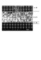
- FIG. 1 shows a cross-section of a layered structure of an article surface according to the invention
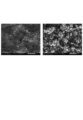
- FIG. 2 shows electron micrographs of a skin layer (left) on the surface of an article according to the present invention and a porous layer (right) after removing the skin layer.
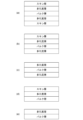
- 1 is a diagram showing a cross-sectional view of an embodiment in which an article according to the invention is in the form of a sheet; FIG.
- the article that diffusely reflects ultraviolet rays, visible rays and/or infrared rays according to the present invention and the method for producing the same will be described below.
- thermoplastic polymers examples include polyethylene (PE), polypropylene (PP), polyamide (PA), polyacetal (POM), polyethylene terephthalate (PET), polybutylene terephthalate (PBT), polylactic acid (PLA), syndiotactic polystyrene. (SPS), polyvinylidene fluoride (PVDF) can be used.
- PE polyethylene
- PP polypropylene
- PA polyamide
- POM polyacetal
- PET polyethylene terephthalate
- PBT polybutylene terephthalate
- PLA polylactic acid
- SPS syndiotactic polystyrene.
- PVDF polyvinylidene fluoride
- thermoplastic polymers a mixture or blend of two or more of the thermoplastic polymers can be used, and the main component of the mixture or blend (in the case of a blend, its continuous phase) is the thermoplastic polymer. It is also possible to use mixtures or blends of said thermoplastic polymer with other thermoplastic polymers different from said thermoplastic polymer. Also, the polymer may be a homopolymer or a copolymer. From the point of view of diffuse reflectance, block copolymers are advantageous, for example block copolymers of polypropylene composed of propylene and ethylene.
- block copolymers or polymer blends having a sea-island structure is advantageous from the standpoint of diffuse reflectance over the entire range (UV, VIS and IR) including ultraviolet light.
- the "sea-island structure” means, for example, in the case of a block copolymer whose main component is polypropylene, a copolymer component or a mixture component (for example, polyethylene) is discontinuous within a region (sea) in which polypropylene (homo PP) is continuous. Refers to a distributed (island) structure.
- polymer blend two or more incompatible polymers with different chemical structures are melt-kneaded to form a continuous sea region and discontinuously dispersed island regions within the sea region.
- a "sea-island structure" is obtained.
- copolymer components or mixed components include, in addition to ethylene, olefin compounds such as methacrylic acid, methyl methacrylate, ethyl methacrylate, butyl methacrylate, methyl acrylate, ethyl acrylate, butyl acrylate and vinyl acetate, Combinations of these polymers can be used.
- thermoplastic polymers that can be used according to the invention, for example, TIPPLEN H681F, H649FH, H145F, K793, K597, K691, K199, K395A, K948, etc. can be used.
- TIPPLEN K793, K597, K691, K199, K395A, K948 are polypropylene block copolymers obtained from propylene and ethylene. It is more resistant to sunlight and UV rays than general-purpose polymers, and may become brittle or deteriorate when used outdoors in direct sunlight or when used as a UV reflector for a long period of time. It is advantageous to use PVDF that is free of
- the article that diffusely reflects ultraviolet light, visible light and/or infrared light comprises at least one skin layer, at least one porous layer formed in contact with the skin layer, and formed in contact with the porous layer. It has a layered structure built up in the order described above from the bulk layers formed.
- FIG. 1 is an electron micrograph of a cross-sectional view of an article according to the invention.
- a “skin layer” according to the present invention is a layer formed on the surface of an article by contacting a molded article made of a thermoplastic polymer with a solvent by the method according to the present invention.
- the article according to the invention has a high reflectance for UV, visible and/or IR radiation, preferably above 60%, more preferably above 70%, particularly preferably above 80%, especially It can be diffusely reflected with a reflectance of greater than 90%.
- the skin layer can also be peeled off from the underlying porous layer.
- the article according to the present invention has a layered structure composed of at least one porous layer and a bulk layer formed in contact with the porous layer in the order described above.
- the diffuse reflectance on the surface of the article according to the present invention can be measured using a PerkinElmer LAMBDA 1050+ UV/Vis/NIR Spectrophotometer (using a 150 mm integrating sphere, fixed at 8°). Reflectance is measured at various wavelengths. The measurement results can be expressed in relative reflectance, with the reflectance of the Spectralon 1050 calibration sample being 100%.
- the "porous layer” according to the present invention is a porous layer formed by contacting a molded body made of a thermoplastic polymer with a solvent by the method according to the present invention, and the skin formed on the surface of the article. exists under the layer.
- the voids (pores) of the porous layer are formed by transcrystallization by TIPS (Thermally Induced Phase Separation) technology and/or by partial dissolution of the thermoplastic polymer that constitutes the article. .
- TIPS Thermally Induced Phase Separation
- the size of the voids (pores) in the porous layer can be reduced.
- FIG. 2 shows electron micrographs of the surface of the skin layer and the surface of the porous layer after removing the skin layer.
- the porous layer after removal of the skin layer like the surface of the skin layer, also has a high UV, visible and/or infrared radiation, particularly preferably all radiation in the UV, visible and infrared ranges. It can be diffusely reflected, preferably with a reflectance of more than 60%, more preferably more than 70%, particularly preferably more than 80%, especially more than 90%.
- a “bulk layer” according to the present invention is a layer that maintains the original composition and structure of a molding made of a thermoplastic polymer prior to contact with a solvent.
- the bulk layer is that part of the article after solvent treatment which was unaffected by the contacting of the thermoplastic compact with the solvent by the method according to the invention, and which is below the porous layer.
- It is a layer of thermoplastic polymer present on the side or inside.
- the crystallinity of the bulk layer is usually 25 to 60%, but it is conceivable that the preferred range of the crystallinity may vary depending on the type of thermoplastic polymer that constitutes the bulk layer. For example, it is 25-50% for block copolymers of polypropylene (PP), 30-50% for homopolymers of PP, and 35-60% for homopolymers of polyvinylidene fluoride (PVDF).
- PP polypropylene
- PVDF polyvinylidene fluoride
- the skin layer, the porous layer, and the bulk layer are formed by treating a molding made of a thermoplastic polymer with a solvent by a predetermined method. are composed of the same thermoplastic polymer.
- the skin layer and the porous layer can be clearly distinguished at their boundaries, and the skin layer can also be peeled off from the porous layer, while these layers are separated from the thermoplastic polymer composing the article. It does not contain a different material different from the one used, nor is it formed by coating or the like. The same applies to the porous layer and the bulk layer.
- the skin layer can be removed immediately after manufacturing the article according to the present invention, or can be left unremoved until just before the article is used for the purpose of protecting the surface of the article.
- the surface of the removed skin layer, which was in contact with the porous layer, also has a hierarchical crystal structure composed of microstructures and nanostructures, similar to the porous layer. Therefore, the peeled skin layer can also be used as a film that diffusely reflects ultraviolet rays, visible rays and/or infrared rays.
- the thickness of the at least one skin layer varies over a wide range depending on various conditions, such as the type of thermoplastic polymer and solvent, and the time and temperature for contacting the molded body made of the thermoplastic polymer with the solvent. sell.
- the thickness of said at least one skin layer is between 5 and 700 ⁇ m, preferably between 5 and 500 ⁇ m.
- the thickness of the skin layer may be less than the thickness range and may be greater than the thickness range.
- the thickness of the at least one porous layer varies widely depending on various conditions such as the type of thermoplastic polymer and solvent, and the time and temperature for contacting the molded body made of the thermoplastic polymer with the solvent. It can vary within a range.
- the thickness of said at least one porous layer is between 20 and 1000 ⁇ m, preferably between 20 and 700 ⁇ m. However, the thickness of the porous layer may be less than the thickness range and may be greater than the thickness range.
- the thickness of said at least one skin layer relative to the thickness of said at least one porous layer may be between 0.5% and 400%, preferably between 0.76 and 325%. be.
- the thickness of the at least one skin layer with respect to the thickness of the at least one porous layer may be constant or may vary. You may When the thickness of the at least one skin layer with respect to the thickness of the at least one porous layer varies in one compact, the variation may be up to about 275%.
- the thermoplastic polymer constituting the article does not contain foreign material different from the material constituting the article.
- the thermoplastic polymer constituting said article contains additives customary in the field of plastics, such as nucleating agents, flame retardants, antioxidants, UV absorbers, stabilizers, fillers, antistatic agents.
- additives customary in the field of plastics, such as nucleating agents, flame retardants, antioxidants, UV absorbers, stabilizers, fillers, antistatic agents.
- additives selected from the group consisting of agents, lubricants, dispersants, reinforcing agents, colorants, diffuse reflectors, conductive fillers and thermally conductive fillers may be added.
- the above additives are merely examples, and other additives may be added to the thermoplastic polymer instead of or in addition to these additives.
- the diffuse reflectance of the article according to the invention can be further improved by adding eg a TiO 2 filler as a diffuse reflector to the thermoplastic polymer.
- the article that diffusely reflects ultraviolet light, visible light and/or infrared light according to the present invention may have any shape.
- the article according to the invention has the shape of a flat film, sheet or plate, or has the shape of a film, sheet or plate with folds, or has a three-dimensional shape.
- may be Molded bodies having a thickness of 1 mm or more are generally called plates or boards.
- a film refers to a membranous material having a thickness of less than 250 ⁇ m
- a sheet refers to a thin plate-like material having a thickness of 250 ⁇ m or more.
- FIG. 3 illustrates an embodiment in which the article according to the invention is sheet-like or plate-like.
- a porous layer and a skin layer may be formed on both sides of the bulk layer, respectively, as shown in FIG. 3(a), or as shown in FIG. 3(c), A porous layer and a skin layer may be formed only on one side of the bulk layer.
- the skin layer on one side is peeled off to obtain the structure shown in FIG. 3(b), and the skin layers on both sides are peeled off.
- FIG. 3(c) it is also possible to obtain an article in which the porous layers are exposed on both sides.
- FIGS. 3(a), (b), and (c) are obtained when both sides of a sheet-like or plate-like article are brought into contact with a solvent by the method according to the present invention described below. and the structures shown in (d) and (e) of FIG. 3 are obtained when only one side of the sheet-like or plate-like article is brought into contact with the solvent by the method according to the present invention. are examples only and are not intended to limit the invention.
- the present invention further provides a method of manufacturing an article that diffusely reflects the ultraviolet rays, visible rays and/or infrared rays.
- the article comprises at least (a) a step of contacting a molded body made of a thermoplastic polymer with a solvent; (b) drying and cooling the compact that has been brought into contact with the solvent.
- the solvent has a boiling point higher than the crystallization temperature (Tc) of the thermoplastic polymer, and the difference between the Hildebrand solubility parameter (SP value) of the solvent and the Hildebrand solubility parameter of the thermoplastic polymer is Any solvent can be used as long as it meets the two requirements of being less than 7.5 MPa 1/2 .
- the difference between the SP value of the solvent and the SP value of the thermoplastic polymer is preferably less than 7.2 MPa 1/2 , more preferably 5.25 MPa 1 /2 , more preferably less than 5 MPa 1/2 .
- solvents examples include n-pentane, n-hexane, n-heptane, n-octane, n-nonane, n-decane, n-undecane, n-dodecane, diethyl ether, cyclohexane, xylene, decalin, and ethyl acetate.
- the SP value of a solvent is for numerically estimating the interaction of multiple substances, and serves as a measure of the solubility of a substance.
- the Hildebrand SP value can be determined based on existing database information, and can be estimated from UV measurement, swelling degree, cloud point, theoretical calculation, etc. of the solution (unit: MPa 2/1 ).
- the preferred solvents are xylene, decalin, and butyl acetate.
- the preferred solvent is decalin.
- the preferred solvent is DMSO.
- the temperature of the solvent when the solvent is brought into contact with a molded article made of a thermoplastic polymer for example, a molded article having the shape of a film, a sheet or a plate is
- the crystallization temperature (Tc) of the polymer is ⁇ 50° C. or higher, preferably the crystallization temperature (Tc) of the thermoplastic polymer is ⁇ 10° C. or higher, and the boiling point or lower of the solvent (Tc of the thermoplastic polymer is ⁇ 50° C., preferably may be in a liquid phase or a gas phase, as long as the Tc of the thermoplastic polymer - 10°C ⁇ the solvent temperature during the treatment in step (a) ⁇ the boiling point of the solvent).
- the preferred temperature range is about 90 to 160°C, and the more preferred temperature range is about 110 to 150°C.
- the molded article made of a thermoplastic polymer may be brought into contact with the solvent over its entire surface, or if necessary, only a part of its surface, for example, in the case of a sheet-like molded article, may be contacted with the solvent. Only one side may be contacted with the solvent.
- the contact time depends on the type of thermoplastic polymer and solvent used, the temperature at which the compact and solvent are contacted, and the efficiency of the process, but is preferably at least 30 seconds. This contact time is usually on the order of 30 seconds to 10 minutes from the standpoint of obtaining a good diffusely reflective surface and forming a continuous, peelable skin layer.
- the preheating temperature is not particularly limited, but from the viewpoint of process efficiency, it is preferably below the temperature at which the compact and the solvent are brought into contact.
- step (b) the solvent is removed from the compact that has been brought into contact with the solvent at a predetermined treatment temperature in step (a), and the compact is dried and cooled.
- the temperature for drying the molded article may be ambient temperature or room temperature, and from the viewpoint of forming a good skin layer, the drying temperature is preferably at least 20° C. higher than the Tc of the thermoplastic polymer constituting the molded article. is advantageously at least 30°C lower.
- the drying in step (b) may be preferably carried out multiple times at the same or different temperatures using the same or different drying means. .
- the drying means and drying temperature used in the method according to the invention are not particularly limited, but from the point of view of process efficiency, the temperature of the drying step or steps preceding the last drying step should exceed the temperature of the last drying step. preferably not.
- the method for producing the article that diffusely reflects ultraviolet rays, visible rays and/or infrared rays according to the present invention may be carried out in a batch mode or a continuous mode. Which mode is used depends on the shape of the molded article, manufacturing equipment, etc., but is not particularly limited as long as the method according to the present invention can be carried out.
- TSA co-rotating twin-screw extruder
- Example 2 A sheet obtained by extrusion molding in the same manner as in Example 1 from a polypropylene homopolymer (TIPPLEN H681F, manufactured by MOL Petrochemical Co., Ltd. in Hungary, crystallization temperature Tc: 109 ° C.) was extruded at 120 ° C. xylene (isomer mixture , CAS number: 1330-20-7, industrial grade, obtained from VWR international Ltd.) was immersed in the bath for 60 seconds.
- TIPPLEN H681F polypropylene homopolymer
- Example 3 The sheet was treated in the same manner as in Example 2, and after drying, the skin layer formed on the surface of the sheet was removed.
- Example 4 The sheet was treated as in Example 2, except the solvent temperature was 110°C.
- Example 5 A sheet obtained by extrusion molding in the same manner as in Example 1 from a polypropylene block copolymer (TIPPLEN K691, manufactured by MOL Petrochemical Co., Ltd.
- Example 6 A sheet obtained by extrusion molding in the same manner as in Example 1 from a polypropylene block copolymer (TIPPLEN K793, manufactured by MOL Petrochemical Co., Ltd.
- Example 7 A sheet obtained by extrusion molding in the same manner as in Example 1 from a polypropylene block copolymer (TIPPLEN K793, manufactured by MOL Petrochemical Co., Ltd.
- Example 8 A polyvinylidene fluoride sheet (PVDF, Simona 030001921) was immersed in a 110° C. DMSO (CAS number: 67-68-5, >99.0% purity, obtained from VWR international Ltd.) bath for 180 seconds.
- Example 1 A sheet obtained by extrusion molding in the same manner as in Example 1 from a polypropylene random copolymer (TIPPLEN R780, manufactured by MOL Petrochemical Co., Ltd. in Hungary, a random copolymer of propylene and ethylene, crystallization temperature Tc: 97.8 ° C.) was immersed in a xylene (isomer mixture, CAS number: 1330-20-7, industrial grade, obtained from VWR international Ltd.) bath at 110° C. for 60 seconds. The sheets were then dried in a drying oven at ambient temperature.
- TIPPLEN R780 manufactured by MOL Petrochemical Co., Ltd. in Hungary, a random copolymer of propylene and ethylene, crystallization temperature Tc: 97.8 ° C.
- [Comparative Example 2] A sheet obtained by extrusion in the same manner as in Example 1 from a polypropylene block copolymer (TIPPLEN K691, manufactured by MOL Petrochemical Co., Ltd. in Hungary, block copolymer of propylene and ethylene, crystallization temperature Tc: 120°C). No solvent treatment.
- [Comparative Example 3] A sheet obtained by extrusion molding in the same manner as in Example 1 from a polypropylene block copolymer (TIPPLEN K793, manufactured by MOL Petrochemical Co., Ltd., Hungary, block copolymer of propylene and ethylene, crystallization temperature Tc: 111°C). No solvent treatment.
- Example 4 A sheet obtained by extrusion molding in the same manner as in Example 1 from a polypropylene homopolymer (TIPPLEN H681F, manufactured by MOL Petrochemical Co., Ltd. located in Hungary, crystallization temperature Tc: 109°C). No solvent treatment.
- thermoplastic polymer used in these examples and comparative examples its crystallization temperature Tc, melting temperature Tm, solvent bath temperature (treatment temperature), immersion time in the solvent bath (treatment time), and ultraviolet light (222 nm, 273 nm), visible light (500 nm, 600 nm), and infrared light (1600 nm, 2000 nm) are summarized in Table 1 below.
- the method for measuring diffuse reflectance is as follows: Diffuse reflectance on the surface of articles according to the invention was performed using a PerkinElmer LAMBDA 1050+ UV/Vis/NIR Spectrophotometer 150 mm integrating sphere, position fixed at 8°. Reflectance was measured at the various wavelengths described above. The measurement results were expressed as relative reflectance, with the reflectance of the Spectralon 1050 calibration sample set to 100%.
- Examples 1 to 8 according to the invention were treated by contacting molded bodies made of thermoplastic polymers with a solvent at a temperature higher than 50° C. below the crystallization temperature Tc of the respective polymer.
- a layer structure composed of at least one skin layer, at least one porous layer and a bulk layer in the order described above is formed on the surface in contact with the solvent.
- the diffuse reflectance was measured while leaving the skin layer formed on the surface.
- the diffuse reflectance was measured after removing the skin layer formed on the surface.
- high diffuse reflectance was measured for visible light and infrared light.
- high diffuse reflectance was measured not only for visible light and infrared light but also for ultraviolet light.
- Comparative Example 1 using a sheet made of a random copolymer of polypropylene, no peelable skin layer was formed on the treated surface, and the diffuse reflectance was measured for all of ultraviolet light, visible light, and infrared light. I could't.
- Comparative Examples 2 to 4 are sheets made of the polypropylene homopolymer or polypropylene block copolymer used in the Examples, but were not surface-treated with a solvent. In these comparative examples, a certain diffuse reflectance was measured for all of ultraviolet light, visible light, and infrared light, but the value was 30% or less, which is much lower than that of the examples according to the present invention.
- the article according to the present invention can be used in many applications because it diffusely reflects ultraviolet rays, visible rays and/or infrared rays with high reflectance.
- it can be used as a diffuse reflective film in direct view displays used in electronic devices such as instrument panels, portable computer screens, liquid crystal displays (LCDs), or in diffuse reflective photoelectric sensors.
- the article according to the present invention has a high diffuse reflectance of ultraviolet rays, it is possible to improve the efficiency when used in an ultraviolet reaction device, an ultraviolet light source, and an ultraviolet lamp such as a germicidal lamp.
- the article according to the present invention has excellent diffuse reflectance of visible light, it can also be used for, for example, a diffusion type projector screen.
- the article according to the present invention due to the property of being able to diffusely reflect visible light and/or infrared rays with high reflectance, the article according to the present invention, such as a sheet or panel, can be used in the outer wall or interior of a building to provide a certain visual effect or heat shielding effect. You can also get
Abstract
紫外線、可視光線および/または赤外線を拡散反射する物品およびその製造方法を提供する。 (a)熱可塑性ポリマーからなる成形体と溶媒とを接触させる工程と、 (b)前記溶媒と接触させた前記成形体を乾燥させ、かつ冷却する工程と を有する製造する方法において、前記溶媒は、前記熱可塑性ポリマーのTcより高い沸点を有する溶媒から選択され、前記溶媒と前記熱可塑性ポリマーのヒルデブラントによる溶解度パラメータとの差が小さく、前記溶媒と前記成形体とを接触させる際の前記溶媒の温度は、前記熱可塑性ポリマーのTc-50℃以上、好ましくはTc-10℃以上であり、かつ前記溶媒の沸点以下とすることにより、少なくとも1つのスキン層、少なくとも1つの多孔質層およびバルク層から前記の順序で構成された層構造を有しており、少なくとも紫外線、可視光線または赤外線のいずれかの放射線の拡散反射率が60%超である物品が得られる。
Description
本発明は、紫外線(UV)、可視光線(VIS)および/または赤外線(IR)を拡散反射する物品に関する。
拡散反射とは、入射した光が鏡面反射の場合のように1つの角度だけで反射されるのではなく、様々な角度で反射される表面反射である。非特許文献1は、多結晶体、多孔質体、微孔質体、粗面など、異なる方向性を持つ複数の表面からの反射によって拡散反射が得られることを開示している。
光を拡散反射する拡散反射板には、さまざまな製造方法がある。拡散反射板は、通常、反射面を粗面化することで得られる。
可視光の拡散反射は、多くの用途において重要である。電子機器、たとえば計器パネル、ポータブル・コンピュータ・スクリーン、液晶ディスプレイ(LCD)などに使用されている直視型ディスプレイは、補助光(バックライトなど)または環境光に依存しているか否かにかかわらず、画質と画像の強度を最大限に高めるために、拡散反射性の裏面を必要とする。反射率は、バッテリーで駆動される機器のバックライト付き直視型ディスプレイにとっては特に重要であり、反射率の向上は、必要とされる光源の小型化、ひいては電力需要の削減に直結している。
紫外線の拡散反射率は、紫外線反応装置、UV滅菌機や紫外光源のような用途において重要である。
本願の出願時に判明している先行技術のうち、本発明と関連性の高いものは以下のとおりである。
特許文献1は、ポリオレフィン樹脂と充填材、たとえば平均粒径0.05~1.5μmの無機充填材5~75重量%とを含有する光反射板を開示している。この光反射板は、15~60%の空隙率を有し、少なくとも単軸方向に配向した白色ポリオレフィンフィルムで形成されたものであり、95%以上の全光線反射率(波長範囲400~700nm)を有しており、70℃で300時間放置した場合に最大で1.5%の寸法変化を生じ、70℃以上の融解開始温度を有するものであることが記載されている。
特許文献2は、ディスプレイや偽造防止のために使用される光学素子を開示している。ここでは、基材の上に設けられたマイクロ構造と前記マイクロ構造上に設けられたナノ構造(階層構造を有する表面)が、光学的効果をもたらす。このような表面の構造化は機械的に、たとえば型押しのような表面パターニングによって形成される。
特許文献3は、基材白色フィルムの少なくとも片面に、球状粒子を含有する被覆層を有する、バックライト用白色反射フィルムを開示している。この球状粒子として、実施例では8~40μmの範囲の体積平均粒径を有するアクリル樹脂やナイロン樹脂(ポリアミド)からなる粒子が使用されている。
特許文献4は、ポリマーと希釈剤とを混合し、熱によってこれらの成分の相分離を誘発して多孔質のポリマーシートを形成し、このシートに力を加えて厚さを変えることで得られる拡散反射材を開示している。このようにして得られた反射材は多孔質であり、その表面は粗いことが記載されている。
特許文献5は、バックライト等において使用される拡散反射板と、その製造を開示している。実施例では型押し用の冷却ロールが使用されている。
特許文献6は、直径1000nm未満のナノファイバーを使用して可視光を拡散反射するデバイスを開示している。
特許文献7は、反射板の製造方法に関するものであり、たとえば直径0.1~3μmのビーズをポリマーによって基材上に固定することにより、反射板表面を作成することを開示している。それぞれのビーズの大きさは、隣接するビーズの大きさとは異なるものであることが記載されている。
特許文献8は、溶融加工可能なアクリル樹脂組成物を使用することによって、基材を必要とすることなく反射板が製造できることを開示している。
特許文献9は、可視光を拡散反射する反射板に関するものであり、不織布の片面に、可視光を拡散反射する材料を含有するバインダー層を設けることを開示している。
特許文献10は、液晶ディスプレイ(LCD)で使用される反射板として、溶媒キャスト法により製造されたフィルムを使用することを開示している。
A. K. R. Choudhury, Colour and appearance attributes. Principles of Colour and Appearance Measurement, pp. 103-143 (2014)
本発明は、上記の事情に鑑み、熱可塑性ポリマー材料からなる物品であって、従来技術によれば光を拡散反射させるために必要とされていたものの、材料のリサイクルを困難または不可能にするような異種材料、たとえばガラスビーズやシリカ等の無機充填材またはナノファイバーを含んでいなくても、また、物品を構成する材料とは異なる異種材料からなる被覆等を有していなくても、紫外線(UV)、可視光線(VIS)および/または赤外線(IR)を拡散反射することができる物品、ならびにそのような物品を製造する方法を提供することを目的としている。
本発明の構成は、以下のとおりである
[1]紫外線、可視光線および/または赤外線を拡散反射する物品であって、前記物品は熱可塑性ポリマーからなり、かつ少なくとも1つのスキン層、前記スキン層に接して形成されている少なくとも1つの多孔質層、および前記多孔質層に接して形成されているバルク層から前記の順序で構成された層構造を有しているか、または少なくとも1つの多孔質層、および前記多孔質層に接して形成されているバルク層から前記の順序で構成された層構造を有している物品。
[2]前記少なくとも1つのスキン層、前記少なくとも1つの多孔質層および前記バルク層は、同一の熱可塑性ポリマーから構成されている、[1]に記載の物品。
[3]前記バルク層の結晶化度は、25%以上60%以下である、[1]または[2]に記載の製品。
[4]前記熱可塑性ポリマーは、ポリエチレン(PE)、ポリプロピレン(PP)、ポリアミド(PA)、ポリアセタール(POM)、ポリエチレンテレフタレート(PET)、ポリブチレンテレフタレート(PBT)、ポリ乳酸(PLA)、シンジオタクチックポリスチレン(SPS)、ポリフッ化ビニリデン(PVDF)からなる群から選択される結晶性または半結晶性の熱可塑性ポリマーであるか、または前記熱可塑性ポリマー2種類以上の混合物もしくはブレンド、または前記熱可塑性ポリマーと、前記熱可塑性ポリマーとは異なる他の熱可塑性ポリマーとの混合物もしくはブレンドである、[1]から[3]までのいずれか1つに記載の物品。
[5]前記結晶性の熱可塑性ポリマーは、ポリプロピレンのホモポリマーである、[4]に記載の物品。
[6]前記結晶性のポリマーは、ポリプロピレンのブロックコポリマーである、[4]に記載の物品。
[7]前記結晶性または半結晶性のポリマーは、ポリフッ化ビニリデンである、[4]に記載の物品。
[8]前記ポリマーは、成核剤、難燃剤、酸化防止剤、紫外線吸収剤、安定剤、充填剤、帯電防止剤、滑剤、分散剤、強化材、着色剤、拡散反射剤、導電性フィラーおよび熱伝導性フィラーからなる群から選択される1種以上の添加剤が添加されている、[1]から[7]までのいずれか1つに記載の物品。
[9]少なくとも紫外線、可視光線または赤外線のいずれかの放射線の拡散反射率が60%超である、[1]から[8]までのいずれか1つに記載の物品。
[10]前記少なくとも1つのスキン層の厚さは、5~700μmである、[1]から[9]までのいずれか1つに記載の物品。
[11]前記少なくとも1つのスキン層の厚さは、5~500μmである、[10]に記載の物品。
[12]前記少なくとも1つの多孔質層の厚さは、20~1000μmである、[1]から[11]までのいずれか1つに記載の物品。
[13]前記少なくとも1つの多孔質層の厚さは、20~700μmである、[12]に記載の物品。
[14]平坦なフィルム、シートもしくは板の形状を有しているか、または折曲部を有するフィルム、シートもしくは板の形状を有しているか、または立体的な形状を有している、[1]から[13]までのいずれか1つに記載の物品。
[15][1]から[14]までのいずれか1つに記載の紫外線、可視光線および/または赤外線を拡散反射する物品を製造する方法であって、
(a)熱可塑性ポリマーからなる成形体と溶媒とを接触させる工程と、
(b)前記溶媒と接触させた前記成形体を乾燥させ、かつ冷却する工程と
を有し、前記溶媒は、前記熱可塑性ポリマーの結晶化温度(Tc)より高い沸点を有する溶媒から選択され、前記溶媒のヒルデブラントによる溶解度パラメータと前記熱可塑性ポリマーのヒルデブラントによる溶解度パラメータとの差は7.5MPa1/2未満であり、前記溶媒と前記成形体とを接触させる際の前記溶媒の温度は、前記熱可塑性ポリマーの結晶化温度(Tc)-50℃以上であり、かつ前記溶媒の沸点以下である、前記物品を製造する方法。
[16]前記溶媒と前記成形体とを接触させる際の前記溶媒の温度は、前記熱可塑性ポリマーの結晶化温度(Tc)-10℃以上であり、かつ前記溶媒の沸点以下である、[15]に記載の方法。
[17]前記溶媒と前記成形体とを接触させる時間は、30秒~10分である、[15]または[16]に記載の方法。
[18]前記溶媒と前記成形体とを接触させる温度は、90~160℃である、[15]から[17]までのいずれか1つに記載の方法。
[19]前記工程(b)に引き続き、物品の表面に形成されたスキン層を除去する、[15]から[18]までのいずれか1つに記載の方法。
本発明による熱可塑性ポリマーからなる物品は、物品を構成する材料とは異なる異種材料を含有することなく、また異種材料からなる被覆等を有することなく、赤外線、好ましくは可視光線と赤外線、さらに好ましくは紫外線と可視光線と赤外線とを高い反射率で、たとえば60%超、好ましくは70%超、さらに好ましくは80%超、特に90%超の反射率で拡散反射することができる。
また、本発明によれば、熱可塑性ポリマーからなる成形体を、所定の条件で溶媒と接触させ、その後に乾燥させるという簡単な工程を経るのみで、上記の物品を製造することができる。
以下に、本発明による紫外線、可視光線および/または赤外線を拡散反射する物品およびその製造方法について詳細に説明する。
本発明による紫外線、可視光線および/または赤外線を拡散反射する物品は、結晶性または半結晶性の熱可塑性ポリマーからなる。前記熱可塑性ポリマーとして、たとえばポリエチレン(PE)、ポリプロピレン(PP)、ポリアミド(PA)、ポリアセタール(POM)、ポリエチレンテレフタレート(PET)、ポリブチレンテレフタレート(PBT)、ポリ乳酸(PLA)、シンジオタクチックポリスチレン(SPS)、ポリフッ化ビニリデン(PVDF)を使用することができる。また、本発明によれば、前記熱可塑性ポリマー2種類以上の混合物またはブレンドを使用することもできるし、混合物またはブレンドの主成分(ブレンドの場合、その連続相)が前記熱可塑性ポリマーであれば、前記熱可塑性ポリマーと、前記熱可塑性ポリマーとは異なる他の熱可塑性ポリマーとの混合物またはブレンドを使用することもできる。また、前記ポリマーは、ホモポリマーでもコポリマーでもよい。拡散反射率の観点から、ブロックコポリマー、たとえばプロピレンと、エチレンとから構成されたポリプロピレンのブロックコポリマーが有利である。特に、紫外線も含む全範囲(UV、VISおよびIR)の拡散反射率という観点からは、海島構造を有するブロックコポリマーまたはポリマーブレンドを用いた場合が有利である。「海島構造」とは、たとえば主成分がポリプロピレンであるブロックコポリマーの場合、ポリプロピレン(ホモPP)が連続する領域(海)の内に、共重合体成分もしくは混合物成分(たとえばポリエチレン)が不連続に(島状で)分散している構造をいう。また、ポリマーブレンドの場合、化学構造が異なる非相容性のポリマー2種類以上を溶融混練することにより、連続する海の領域と、海の領域内に不連続に分散する島の領域とからなる「海島構造」が得られる。たとえば、プロピレンとエチレンとから構成されたブロックコポリマー、またはポリプロピレンとポリエチレンとが混合されたポリマーブレンドなどを挙げることができる。共重合体成分もしくは混合成分の例としては、上記エチレンのほかに、メタクリル酸、メタクリル酸メチル、メタクリル酸エチル、メタクリル酸ブチル、メチルアクリレート、エチルアクリレート、ブチルアクリレート、酢酸ビニルなどのオレフィン化合物や、これらの重合体を組み合わせて使用することができる。本発明により使用することができる熱可塑性ポリマーとして、たとえばTIPPLEN H681F、H649FH、H145F、K793、K597、K691、K199、K395A、K948等を使用することができる。TIPPLEN K793、K597、K691、K199、K395A、K948は、プロピレンと、エチレンとから得られるポリプロピレンブロックコポリマーである。直射日光に曝される屋外での使用や、紫外線反射板として長期間にわたる使用が想定される場合には、汎用ポリマーに比べて太陽光線や紫外線に対して耐性があり、脆化もしくは劣化する懸念のないPVDFを使用することが有利である。
本発明による紫外線、可視光線および/または赤外線を拡散反射する物品は、少なくとも1つのスキン層、前記スキン層に接して形成されている少なくとも1つの多孔質層、および前記多孔質層に接して形成されているバルク層から前記の順序で構成された層構造を有している。図1は、本発明による物品の断面図の電子顕微鏡写真である。
本発明による「スキン層」とは、熱可塑性ポリマーからなる成形体を、本発明による方法によって溶媒と接触させることで物品の表面に形成された層である。本発明による物品は、このスキン層を備えた状態で、紫外線、可視光線および/または赤外線を高い反射率で、好ましくは60%超、さらに好ましくは70%超、特に好ましくは80%超、とりわけ90%超の反射率で拡散反射することができる。
なお、スキン層は、その下に存在する多孔質層から剥離することもできる。スキン層を剥離した場合、本発明による物品は、少なくとも1つの多孔質層、および前記多孔質層に接して形成されているバルク層から前記の順序で構成された層構造を有している。
なお、スキン層は、その下に存在する多孔質層から剥離することもできる。スキン層を剥離した場合、本発明による物品は、少なくとも1つの多孔質層、および前記多孔質層に接して形成されているバルク層から前記の順序で構成された層構造を有している。
本発明による物品表面における拡散反射率は、パーキンエルマー社製LAMBDA 1050+ UV/Vis/NIR Spectrophotometer(150mm積分球を使用、位置を8°に固定)を用いて測定することができる。反射率は様々な波長で測定される。測定結果は、Spectralon 1050キャリブレーションサンプルの反射率を100%として、相対反射率で表すことができる。
本発明による「多孔質層」とは、熱可塑性ポリマーからなる成形体を、本発明による方法によって溶媒と接触させることで形成された多孔質の層であり、物品の表面に形成された前記スキン層の下に存在する。多孔質層の空隙(細孔)は、TIPS(Thermally Induced Phase Separation)技術によるトランス結晶化(transcrystallization)によって、および/または物品を構成する熱可塑性ポリマーの部分的な溶解によって形成されるものである。本発明によれば、物品を構成する熱可塑性ポリマーが上記の「海島構造」を有する共重合体である場合、多孔質層の空隙(細孔)のサイズを小さくすることができ、これにより、本発明による物品において、短波長(UV)側の拡散反射率が高められることが判明した。前記スキン層を除去した後の多孔質層の表面は、球晶状のマイクロ構造とナノ構造とから形成された、階層的な結晶構造を示す。図2は、スキン層の表面およびスキン層を除去した後の多孔質層の表面の電子顕微鏡写真を示している。スキン層を除去した後の多孔質層も、スキン層の表面と同様に、紫外線、可視光線および/または赤外線を、特に有利には、紫外線、可視光線および赤外線の範囲の全ての放射線を、高い反射率で、好ましくは60%超、さらに好ましくは70%超、特に好ましくは80%超、とりわけ90%超の反射率で拡散反射することができる。
本発明による「バルク層」とは、溶媒と接触させる前の熱可塑性ポリマーからなる成形体の当初の組成および構造を維持している層である。換言すれば、バルク層とは、本発明による方法によって熱可塑性成形体と溶媒とを接触させることによっても影響を受けなかった部分であって、溶媒処理後の物品において、前記多孔質層の下側もしくは内側に存在する熱可塑性ポリマーからなる層である。バルク層の結晶化度は、通常、25~60%であるが、この結晶化度は、バルク層を構成する熱可塑性ポリマーの種類によって好ましい範囲が異なることも考えられる。たとえばポリプロピレン(PP)のブロックコポリマーでは、25~50%、PPのホモポリマーでは、30~50%、ポリフッ化ビニリデン(PVDF)のホモポリマーでは35~60%である。
なお、本発明によれば、前記スキン層、前記多孔質層、および前記バルク層は、熱可塑性ポリマーからなる成形体を所定の方法で溶媒によって処理することにより形成されるものであるため、これらの層はいずれも同一の熱可塑性ポリマーから構成されている。従って、前記スキン層と前記多孔質層は、それらの境界を明確に区別でき、スキン層を多孔質層から剥離することもできる一方で、これらの層は、物品を構成している熱可塑性ポリマーとは異なる異種材料を含むものではなく、また、被覆等によって形成されたものでもない。前記多孔質層と前記バルク層についても同様である。スキン層は、本発明による物品を製造した直後に除去することもできるし、物品表面を保護するため等の目的で、物品を使用する直前まで除去しないでおくこともできる。除去後のスキン層も、多孔質層と接触していた側の表面に、多孔質層と同様に、マイクロ構造とナノ構造とから構成される階層的な結晶構造が形成されている。従って、剥離後のスキン層も、紫外線、可視光線および/または赤外線を拡散反射するフィルムとして使用することができる。
本発明によれば、前記少なくとも1つのスキン層の厚さは、熱可塑性ポリマーや溶媒の種類、熱可塑性ポリマーからなる成形体と溶媒とを接触させる時間や温度といった諸条件によって広い範囲で変動しうる。前記少なくとも1つのスキン層の厚さは5~700μm、好ましくは5~500μmである。しかし、スキン層の厚さは前記の範囲の厚さを下回ってもよいし、前記の範囲の厚さを上回ってもよい。
また、前記少なくとも1つの多孔質層の厚さも前記スキン層の場合と同様に、熱可塑性ポリマーや溶媒の種類、熱可塑性ポリマーからなる成形体と溶媒とを接触させる時間や温度といった諸条件によって広い範囲で変動しうる。前記少なくとも1つの多孔質層の厚さは、20~1000μm、好ましくは20~700μmである。しかし、多孔質層の厚さは前記の範囲の厚さを下回ってもよいし、前記の範囲の厚さを上回ってもよい。本発明によれば、前記少なくとも1つの多孔質層の厚さに対する前記少なくとも1つのスキン層の厚さは、0.5%~400%であってもよく、好ましくは0.76~325%である。また、本発明によれば、1つの成形体、たとえば1枚のシートにおいて、前記少なくとも1つの多孔質層の厚さに対する前記少なくとも1つのスキン層の厚さが一定であってもよいし、変動してもよい。前記少なくとも1つの多孔質層の厚さに対する前記少なくとも1つのスキン層の厚さが1つの成形体において変動する場合、その変動値は最大で275%程度までであってもよい。
本発明によれば、前記物品を構成する熱可塑性ポリマーには、物品のリサイクルという観点から、前記物品を構成する材料とは異なる異種材料が含まれていないことが好ましい。しかし、本発明によれば、前記物品を構成する熱可塑性ポリマーに、プラスチック分野において慣用の添加剤、たとえば成核剤、難燃剤、酸化防止剤、紫外線吸収剤、安定剤、充填剤、帯電防止剤、滑剤、分散剤、強化材、着色剤、拡散反射剤、導電性フィラーおよび熱伝導性フィラーからなる群から選択される1種以上の添加剤が添加されていてもよい。前記の添加剤は単なる例示にすぎず、これらの添加剤に代えて、またはこれらの添加剤に加えて、その他の添加剤が、熱可塑性ポリマーに添加されていてもよい。たとえば拡散反射剤としてTiO2フィラーを熱可塑性ポリマーに添加することにより、本発明による物品の拡散反射率をさらに向上することができる。
本発明による紫外線、可視光線および/または赤外線を拡散反射する物品は任意の形状であってよい。たとえば本発明による前記物品は、平坦なフィルム、シートもしくは板の形状を有しているか、または折曲部を有するフィルム、シートもしくは板の形状を有しているか、または立体的な形状を有していてもよい。一般に厚さが1mm以上の成形体は板もしくはボードと呼ばれる。JIS(日本工業規格)によれば、フィルムとは、厚さが250μm未満の膜状のものをいい、シートとは、厚さが250μm以上の薄い板状のものをいう。図3は、本発明による物品がシート状もしくは板状である態様を例示するものである。本発明によれば、図3の(a)に示すように、バルク層の両面にそれぞれ、多孔質層およびスキン層が形成されていてもよいし、図3の(c)に示すように、バルク層の片面のみに多孔質層およびスキン層が形成されていてもよい。また、図3の(a)に示す層構造が得られた後で、片面のスキン層を剥離することによって、図3の(b)に示す構造が得られ、両面のスキン層を剥離することによって、図3の(c)に示すように、その両面で多孔質層が露出した物品とすることも可能である。あるいは、図3の(d)に示す層構造が得られた後で、スキン層を剥離することで、図3の(e)に示す、物品の片面に多孔質層のみを備えた物品とすることもできる。なお、図3の(a)、(b)、(c)に示す構造は、シート状もしくは板状の物品の両面を、以下に記載する本発明による方法によって溶媒と接触させる場合に得られるものであり、図3の(d)、(e)に示す構造は、シート状もしくは板状の物品の片面のみを本発明による方法によって溶媒と接触させる場合に得られるものであるが、これらの態様は例示にすぎず、本発明を限定することを意図するものではない。
本発明はさらに、前記紫外線、可視光線および/または赤外線を拡散反射する物品を製造する方法を提供する。
本発明によれば、前記物品は、少なくとも
(a)熱可塑性ポリマーからなる成形体と溶媒とを接触させる工程と、
(b)前記溶媒と接触させた前記成形体を乾燥させ、かつ冷却する工程と
を有する方法によって製造することができる。
(a)熱可塑性ポリマーからなる成形体と溶媒とを接触させる工程と、
(b)前記溶媒と接触させた前記成形体を乾燥させ、かつ冷却する工程と
を有する方法によって製造することができる。
前記溶媒として、前記熱可塑性ポリマーの結晶化温度(Tc)より高い沸点を有し、かつ前記溶媒のヒルデブラントによる溶解度パラメータ(SP値)と前記熱可塑性ポリマーのヒルデブラントによる溶解度パラメータとの差が7.5MPa1/2未満であるという2つの要件を満たす限り、任意の溶媒を使用することができる。前記溶媒のSP値と前記熱可塑性ポリマーのSP値との差は、良好な拡散反射率を備えた表面を形成する観点から、好ましくは7.2MPa1/2未満、より好ましくは5.25MPa1/2未満、さらに好ましくは5MPa1/2未満である。このような溶媒として、たとえばn-ペンタン、n-ヘキサン、n-ヘプタン、n-オクタン、n-ノナン、n-デカン、n-ウンデカン、n-ドデカン、ジエチルエーテル、シクロヘキサン、キシレン、デカリン、酢酸エチル、酢酸ブチル、ベンゼン、メチルエチルケトン、アセトン、ピリジン、ジエチルアミン、イソ酪酸ブチル、n-酪酸ブチル、塩化ブチル、イソブチルエーテル、ギ酸イソブチル、アクリル酸イソデシル、ジアセトンアルコール、メチルエーテル、テトラリン、アセトニトリル、アクリル酸、ベンジルアルコール、1,4-ブタンジオール、2,3-ブチレンカーボネート、ブチロラクトン、クロロアセトニトリル、ジエチレングリコール、ジエチルスルホン、エチルアセトアミド、エチレンジアミン、ギ酸、フェニルヒドラジン、トリレンジイソシアネート、酢酸、ジメチルスルホキシド(DMSO)、ニトロベンゼン、フェノール、o-クロロフェノール、1,1,1,3,3,3-ヘキサフルオロ-2-プロパノール、o-クレゾール、トルエン、クロロベンゼン、1,2-ジクロロベンゼン、クロロホルム、1,4-ジオキサン、テトラヒドロフラン、またはこれらの溶媒2種類以上の混合物を使用することができる。前記の溶媒は単なる例示にすぎず、上記の2つの要件を満たすものであれば、これらの溶媒に代えて、またはこれらの溶媒に加えて、その他の溶媒を使用することもできる。
溶媒のSP値は、複数の物質の相互作用を数値によって推定するためのものであり、物質の溶解度の目安となるものである。ヒルデブラントによるSP値は、既存のデータベース情報に基づいて決定することができ、溶液のUV測定、膨潤度、曇り点、理論計算などから推定することができる(単位:MPa2/1)。
SP値の差を低減する観点から、前記熱可塑性ポリマーとしてポリプロピレンを使用する場合、好ましい溶媒は、キシレン、デカリン、酢酸ブチルである。前記熱可塑性ポリマーとしてポリエチレンを使用する場合、好ましい溶媒は、デカリンである。また、前記熱可塑性ポリマーとしてPVDFを使用する場合、好ましい溶媒はDMSOである。
前記工程(a)において、溶媒と、熱可塑性ポリマーから構成された成形体、たとえばフィルム、シートもしくは板の形状を有している成形体とを接触させる際の前記溶媒の温度は、前記熱可塑性ポリマーの結晶化温度(Tc)-50℃以上、好ましくは前記熱可塑性ポリマーの結晶化温度(Tc)-10℃以上であり、かつ前記溶媒の沸点以下(熱可塑性ポリマーのTc-50℃、好ましくは熱可塑性ポリマーのTc-10℃<工程(a)における処理の際の溶媒温度≦溶媒の沸点)である限り、液相であっても気相であってもよい。物品表面の拡散反射率および作業効率の観点から、好ましい温度範囲は90~160℃程度、より好ましい温度範囲は110~150℃程度である。なお、熱可塑性ポリマーから構成された成形体は、その表面全体を溶媒と接触させてもよいし、必要に応じて、その表面の一部のみ、たとえばシート状の成形体の場合には、その片面のみを溶媒と接触させてもよい。
前記工程(a)において熱可塑性ポリマーから構成された成形体と溶媒とを接触させる時間は特に限定されない。この接触時間は、使用する熱可塑性ポリマーおよび溶媒の種類、成形体と溶媒とを接触させる際の温度、およびプロセス効率にも依存するが、少なくとも30秒が好ましい。良好な拡散反射表面を得ると共に、連続した、剥離可能なスキン層を形成する観点から、この接触時間は通常、30秒~10分程度である。
なお、プロセス効率の観点から、工程(a)に先だって、溶媒と接触させるべき成形体を予熱することは好ましい。予熱の温度は特に限定されないが、プロセス効率という観点では、成形体と溶媒とを接触させる温度以下が好ましい。
工程(a)に引き続き、工程(b)では、工程(a)において所定の処理温度で溶媒と接触させた成形体から溶媒を除去し、成形体を乾燥させ、かつ冷却する。工程(b)における乾燥の際に、乾燥温度について特に下限値はない。成形体を乾燥させる温度は周囲温度もしくは室温であってもよく、良好なスキン層の形成という観点から、乾燥温度は、成形体を構成している熱可塑性ポリマーのTcよりも少なくとも20℃、好ましくは少なくとも30℃低いことが有利である。スキン層の形成を制御する観点から、工程(b)における乾燥は、同一のまたは異なった乾燥手段を使用して、同一のまたは異なった温度で、複数回に分けて行うことが好ましい場合もある。本発明による方法において使用する乾燥手段、乾燥温度は特に限定されないが、プロセス効率の観点から、最後の乾燥ステップに先行する1つまたは複数の乾燥ステップの温度は、最後の乾燥ステップの温度を超えないことが好ましい。
本発明による前記紫外線、可視光線および/または赤外線を拡散反射する物品を製造する方法は、バッチ式の態様で行ってもよいし、連続式の態様で行ってもよい。いずれの態様で行うかは、成形体の形状や、製造設備等に依存するが、本発明による方法を実施することができる限り、特に制限はない。
以下では、本発明による物品について実施例に基づいて詳細に説明するが、本発明はこれらの実施例による態様に限定されるものではない。
[実施例1]
ポリプロピレンホモポリマー(TIPPLEN H681F、ハンガリー国在MOL石油化学株式会社製、結晶化温度Tc:109℃)から押出成形によってシートを成形した。押出成形は、共回転二軸押出機(イタリア国チェルノッビオ在TSA社、D=32mm、L/D=40)を使用して実施し、温度プロファイルは190℃、200℃、200℃、200℃、200℃に設定した。ダイ温度は200℃とした。前記二軸押出機の回転速度は60回転/分(60min-1)とし、供給速度は6kg/時とした。厚さ1mmのスロットダイを使用した。押出成形により得られたシートを、120℃のキシレン(異性体混合物、CAS番号:1330-20-7、工業用グレード、VWR international Ltd.から入手)浴に30秒間浸漬した。その後、シートを乾燥炉中、周囲温度で乾燥させた。
[実施例2]
ポリプロピレンホモポリマー(TIPPLEN H681F、ハンガリー国在MOL石油化学株式会社製、結晶化温度Tc:109℃)から、実施例1と同様に押出成形によって得られたシートを、120℃のキシレン(異性体混合物、CAS番号:1330-20-7、工業用グレード、VWR international Ltd.から入手)浴に60秒間浸漬した。その後、シートを乾燥炉中、周囲温度で乾燥させた。
[実施例3]
実施例2と同様にシートを処理し、乾燥後、シートの表面に形成されていたスキン層を除去した。
[実施例4]
実施例2と同様にシートを処理したが、ただし溶媒の温度は110℃であった。
[実施例5]
ポリプロピレンブロックコポリマー(TIPPLEN K691、ハンガリー国在MOL石油化学株式会社製、プロピレンとエチレンとのブロックコポリマー、結晶化温度Tc:120℃)から、実施例1と同様に押出成形によって得られたシートを、110℃のキシレン(異性体混合物、CAS番号:1330-20-7、工業用グレード、VWR international Ltd.から入手)浴に60秒間浸漬した。その後、シートを乾燥炉中、周囲温度で乾燥させた。
[実施例6]
ポリプロピレンブロックコポリマー(TIPPLEN K793、ハンガリー国在MOL石油化学株式会社製、プロピレンとエチレンとのブロックコポリマー、結晶化温度Tc:111℃)から、実施例1と同様に押出成形によって得られたシートを、110℃のキシレン(異性体混合物、CAS番号:1330-20-7、工業用グレード、VWR international Ltd.から入手)浴に60秒間浸漬した。その後、シートを乾燥炉中、周囲温度で乾燥させた。
[実施例7]
ポリプロピレンブロックコポリマー(TIPPLEN K793、ハンガリー国在MOL石油化学株式会社製、プロピレンとエチレンとのブロックコポリマー、結晶化温度Tc:111℃)から、実施例1と同様に押出成形によって得られたシートを、120℃のキシレン(異性体混合物、CAS番号:1330-20-7、工業用グレード、VWR international Ltd.から入手)浴に30秒間浸漬した。その後、シートを乾燥炉中、周囲温度で乾燥させた。乾燥後、シートの表面に形成されていたスキン層を除去した。
[実施例8]
ポリフッ化ビニリデンシート(PVDF、Simona 030001921)からを、110℃のDMSO(CAS番号:67-68-5、純度99.0%以上、VWR international Ltd.から入手)浴に180秒間浸漬した。その後、シートを乾燥炉中、周囲温度で乾燥させた。
[比較例1]
ポリプロピレンランダムコポリマー(TIPPLEN R780、ハンガリー国在MOL石油化学株式会社製、プロピレンとエチレンとのランダムコポリマー、結晶化温度Tc:97.8℃)から、実施例1と同様に押出成形によって得られたシートを、110℃のキシレン(異性体混合物、CAS番号:1330-20-7、工業用グレード、VWR international Ltd.から入手)浴に60秒間浸漬した。その後、シートを乾燥炉中、周囲温度で乾燥させた。
[比較例2]
ポリプロピレンブロックコポリマー(TIPPLEN K691、ハンガリー国在MOL石油化学株式会社製、プロピレンとエチレンとのブロックコポリマー、結晶化温度Tc:120℃)から、実施例1と同様に押出成形によって得られたシート。溶媒による処理を行わなかったもの。
[比較例3]
ポリプロピレンブロックコポリマー(TIPPLEN K793、ハンガリー国在MOL石油化学株式会社製、プロピレンとエチレンとのブロックコポリマー、結晶化温度Tc:111℃)から、実施例1と同様に押出成形によって得られたシート。溶媒による処理を行わなかったもの。
[比較例4]
ポリプロピレンホモポリマー(TIPPLEN H681F、ハンガリー国在MOL石油化学株式会社製、結晶化温度Tc:109℃)から、実施例1と同様に押出成形によって得られたシート。溶媒による処理を行わなかったもの。
[結果]
これらの実施例および比較例において使用した熱可塑性ポリマー、その結晶化温度Tc、溶融温度Tm、溶媒浴の温度(処理温度)、溶媒浴中での浸漬時間(処理時間)、ならびに紫外線(222nm、273nm)、可視光線(500nm、600nm)、および赤外線(1600nm、2000nm)の拡散反射率を以下の表1にまとめた。拡散反射率の測定方法は以下のとおりである:
本発明による物品表面における拡散反射率は、パーキンエルマー社製LAMBDA 1050+ UV/Vis/NIR Spectrophotometer150mm積分球を使用、位置を8°に固定)を用いて実施した。反射率を上記の様々な波長で測定した。測定結果は、Spectralon 1050キャリブレーションサンプルの反射率を100%として、相対反射率で表した。
表1の「評価」では、それぞれの波長の反射率が50%未満のものを「×」、50%以上60%以下のものを「○」、60%を超えるものを「◎」とした。

表1に示されているように、本発明による実施例1~8では、熱可塑性ポリマーからなる成形体を、各ポリマーの結晶化温度Tcを50℃下回る温度より高い温度の溶媒と接触させる処理を行うことにより、溶媒との接触表面に少なくとも1つのスキン層、少なくとも1つの多孔質層およびバルク層から前記の順序で構成された層構造が形成される。実施例1、2、4、5、6および8では、表面に形成されたスキン層を残したまま、拡散反射率を測定した。実施例3および7では、表面に形成されたスキン層を除去した後に、拡散反射率を測定した。いずれの実施例においても、可視光線、赤外線について高い拡散反射率が測定された。また、実施例5~8では、可視光線、赤外線に加えてさらに、紫外線についても高い拡散反射率が測定された。
これに対して、ポリプロピレンのランダムコポリマーからなるシートを用いた比較例1では、処理表面に剥離可能なスキン層は形成されず、また紫外線、可視光線、赤外線のいずれについても拡散反射率を測定することはできなかった。
また、比較例2~4は、実施例で使用したポリプロピレンホモポリマーまたはポリプロピレンブロックコポリマーからなるシートであるが、溶媒による表面処理を行わなかったものである。これらの比較例では、紫外線、可視光線、赤外線のいずれについても一定の拡散反射率が測定されたが、30%以下と、本発明による実施例と比較してはるかに低い値であった。
本発明による物品は、紫外線、可視光線および/または赤外線を高い反射率で拡散反射することから、多くの用途において使用することが可能である。たとえば、計器パネル、ポータブル・コンピュータ・スクリーン、液晶ディスプレイ(LCD)などの電子機器に使用されている直視型ディスプレイにおいて拡散反射フィルムとして、または拡散反射型光電センサにおいて使用することができる。また、本発明による物品は、紫外線の拡散反射率が高いことから、紫外線反応装置や紫外光源、殺菌灯のような紫外線ランプにおいて使用する場合にも、効率の向上を図ることができる。
さらに、本発明による物品は可視光の拡散反射率が優れていることから、たとえば拡散型プロジェクタースクリーンに使用することもできる。あるいは可視光および/または赤外線を高い反射率で拡散反射できるという特性から、建築物の外壁や、内装において本発明による物品、たとえばシートやパネルを使用することで、一定の視覚効果や遮熱効果を得ることもできる。
Claims (19)
- 紫外線、可視光線および/または赤外線を拡散反射する物品であって、前記物品は熱可塑性ポリマーからなり、かつ少なくとも1つのスキン層、前記スキン層に接して形成されている少なくとも1つの多孔質層、および前記多孔質層に接して形成されているバルク層から前記の順序で構成された層構造を有しているか、または少なくとも1つの多孔質層、および前記多孔質層に接して形成されているバルク層から前記の順序で構成された層構造を有している物品。
- 前記少なくとも1つのスキン層、前記少なくとも1つの多孔質層および前記バルク層は、同一の熱可塑性ポリマーから形成されている、請求項1に記載の物品。
- 前記バルク層の結晶化度は、25%以上60%以下である、請求項1または2に記載の製品。
- 前記熱可塑性ポリマーは、ポリエチレン(PE)、ポリプロピレン(PP)、ポリアミド(PA)、ポリアセタール(POM)、ポリエチレンテレフタレート(PET)、ポリブチレンテレフタレート(PBT)、ポリ乳酸(PLA)、シンジオタクチックポリスチレン(SPS)、ポリフッ化ビニリデン(PVDF)からなる群から選択される結晶性または半結晶性の熱可塑性ポリマーであるか、または前記熱可塑性ポリマー2種類以上の混合物もしくはブレンド、または前記熱可塑性ポリマーと、前記熱可塑性ポリマーとは異なる他の熱可塑性ポリマーとの混合物もしくはブレンドである、請求項1から3までのいずれか1項に記載の物品。
- 前記結晶性または半結晶性の熱可塑性ポリマーは、ポリプロピレンのホモポリマーである、請求項4に記載の物品。
- 前記結晶性または半結晶性のポリマーは、ポリプロピレンのブロックコポリマーである、請求項4に記載の物品。
- 前記結晶性または半結晶性のポリマーは、ポリフッ化ビニリデンである、請求項4に記載の物品。
- 前記熱可塑性ポリマーには、成核剤、難燃剤、酸化防止剤、紫外線吸収剤、安定剤、充填剤、可塑剤、帯電防止剤、滑剤、分散剤、強化材、着色剤、拡散反射剤、導電性フィラーおよび熱伝導性フィラーからなる群から選択される1種以上の添加剤が添加されている、請求項1から7までのいずれか1項に記載の物品。
- 少なくとも紫外線、可視光線または赤外線のいずれかの放射線の拡散反射率が60%超である、請求項1から8までのいずれか1項に記載の物品。
- 前記少なくとも1つのスキン層の厚さは、5~700μmである、請求項1から9までのいずれか1項に記載の物品。
- 前記少なくとも1つのスキン層の厚さは、5~500μmである、請求項10に記載の物品。
- 前記少なくとも1つの多孔質層の厚さは、20~1000μmである、請求項1から11までのいずれか1項に記載の物品。
- 前記少なくとも1つの多孔質層の厚さは、20~700μmである、請求項12に記載の物品。
- 平坦なフィルム、シートもしくは板の形状を有しているか、または少なくとも1つの折曲部を有するフィルム、シートもしくは板の形状を有しているか、または立体的な形状を有している、請求項1から13までのいずれか1項に記載の物品。
- 請求項1から14までのいずれか1項に記載の紫外線、可視光線および/または赤外線を拡散反射する物品を製造する方法であって、
(a)熱可塑性ポリマーからなる成形体と溶媒とを接触させる工程と、
(b)前記溶媒と接触させた前記成形体を乾燥させ、かつ冷却する工程と
を有し、前記溶媒は、前記熱可塑性ポリマーの結晶化温度(Tc)より高い沸点を有する溶媒から選択され、前記溶媒のヒルデブラントによる溶解度パラメータと前記熱可塑性ポリマーのヒルデブラントによる溶解度パラメータとの差は7.5MPa1/2未満であり、前記溶媒と前記成形体とを接触させる際の前記溶媒の温度は、前記熱可塑性ポリマーの結晶化温度(Tc)-50℃以上であり、かつ前記溶媒の沸点以下である、前記物品を製造する方法。 - 前記溶媒と前記成形体とを接触させる際の前記溶媒の温度は、前記熱可塑性ポリマーの結晶化温度(Tc)-10℃以上であり、かつ前記溶媒の沸点以下である、請求項15に記載の方法。
- 前記溶媒と前記成形体とを接触させる時間は、30秒~10分である、請求項15または16に記載の方法。
- 前記溶媒と前記成形体とを接触させる際の溶媒の温度は、90~160℃である、請求項15から17までのいずれか1項に記載の方法。
- 前記工程(b)に引き続き、物品の表面に形成されたスキン層を除去する、請求項15から18までのいずれか1項に記載の方法。
Applications Claiming Priority (2)
| Application Number | Priority Date | Filing Date | Title |
|---|---|---|---|
| JP2021161976 | 2021-09-30 | ||
| JP2021-161976 | 2021-09-30 |
Publications (1)
| Publication Number | Publication Date |
|---|---|
| WO2023054591A1 true WO2023054591A1 (ja) | 2023-04-06 |
Family
ID=85782902
Family Applications (1)
| Application Number | Title | Priority Date | Filing Date |
|---|---|---|---|
| PCT/JP2022/036457 WO2023054591A1 (ja) | 2021-09-30 | 2022-09-29 | 紫外線、可視光線および/または赤外線を拡散反射する物品およびその製造方法 |
Country Status (1)
| Country | Link |
|---|---|
| WO (1) | WO2023054591A1 (ja) |
Citations (11)
| Publication number | Priority date | Publication date | Assignee | Title |
|---|---|---|---|---|
| JPS4958164A (ja) * | 1972-06-29 | 1974-06-05 | ||
| JPS4936837B1 (ja) * | 1970-02-16 | 1974-10-03 | ||
| JPH0780956A (ja) * | 1993-09-16 | 1995-03-28 | Nissha Printing Co Ltd | 光散乱材の製造方法 |
| JP2007518832A (ja) * | 2003-06-30 | 2007-07-12 | スリーエム イノベイティブ プロパティズ カンパニー | 難燃剤を含有する微孔質物品;フィルムおよびその多層フィルム |
| US20080310169A1 (en) * | 2007-06-18 | 2008-12-18 | Forhouse Cor4Poration | Diffusive plate of backlight module with porous diffusive layer |
| WO2011074418A1 (ja) * | 2009-12-14 | 2011-06-23 | ダイセル化学工業株式会社 | 多孔質層を有する積層体、及びそれを用いた機能性積層体 |
| JP2013508780A (ja) * | 2009-10-24 | 2013-03-07 | スリーエム イノベイティブ プロパティズ カンパニー | 空隙を有するディフューザー |
| KR20130077669A (ko) * | 2011-12-29 | 2013-07-09 | 도레이첨단소재 주식회사 | 광확산용 발포수지 필름 및 그를 이용한 광확산 필름 |
| WO2013137260A1 (ja) * | 2012-03-12 | 2013-09-19 | ナノシータ株式会社 | 高分子超薄膜及び多孔質高分子超薄膜 |
| JP2014202994A (ja) * | 2013-04-08 | 2014-10-27 | 帝人株式会社 | 反射偏光フィルム積層体、それからなる液晶ディスプレイ用光学部材および液晶ディスプレイ |
| CN111933824A (zh) * | 2020-07-06 | 2020-11-13 | 华南理工大学 | 一种作为光取出层的微透镜、散射层及其制备方法 |
-
2022
- 2022-09-29 WO PCT/JP2022/036457 patent/WO2023054591A1/ja active Application Filing
Patent Citations (11)
| Publication number | Priority date | Publication date | Assignee | Title |
|---|---|---|---|---|
| JPS4936837B1 (ja) * | 1970-02-16 | 1974-10-03 | ||
| JPS4958164A (ja) * | 1972-06-29 | 1974-06-05 | ||
| JPH0780956A (ja) * | 1993-09-16 | 1995-03-28 | Nissha Printing Co Ltd | 光散乱材の製造方法 |
| JP2007518832A (ja) * | 2003-06-30 | 2007-07-12 | スリーエム イノベイティブ プロパティズ カンパニー | 難燃剤を含有する微孔質物品;フィルムおよびその多層フィルム |
| US20080310169A1 (en) * | 2007-06-18 | 2008-12-18 | Forhouse Cor4Poration | Diffusive plate of backlight module with porous diffusive layer |
| JP2013508780A (ja) * | 2009-10-24 | 2013-03-07 | スリーエム イノベイティブ プロパティズ カンパニー | 空隙を有するディフューザー |
| WO2011074418A1 (ja) * | 2009-12-14 | 2011-06-23 | ダイセル化学工業株式会社 | 多孔質層を有する積層体、及びそれを用いた機能性積層体 |
| KR20130077669A (ko) * | 2011-12-29 | 2013-07-09 | 도레이첨단소재 주식회사 | 광확산용 발포수지 필름 및 그를 이용한 광확산 필름 |
| WO2013137260A1 (ja) * | 2012-03-12 | 2013-09-19 | ナノシータ株式会社 | 高分子超薄膜及び多孔質高分子超薄膜 |
| JP2014202994A (ja) * | 2013-04-08 | 2014-10-27 | 帝人株式会社 | 反射偏光フィルム積層体、それからなる液晶ディスプレイ用光学部材および液晶ディスプレイ |
| CN111933824A (zh) * | 2020-07-06 | 2020-11-13 | 华南理工大学 | 一种作为光取出层的微透镜、散射层及其制备方法 |
Similar Documents
| Publication | Publication Date | Title |
|---|---|---|
| TW527507B (en) | White film for surface light source | |
| KR101238791B1 (ko) | 백색 폴리에스테르 필름 및 반사시트 | |
| CN101910881B (zh) | 反射片用白色叠层聚酯膜 | |
| TW200829962A (en) | White polyester film for light reflecting plate | |
| CN101596802A (zh) | 一种光学用聚酯薄膜及其制备方法 | |
| JP2007183423A (ja) | 電子ペーパー用ポリエステルフィルム | |
| EP2751176B1 (en) | Optical film and preparation method thereof | |
| WO2023054591A1 (ja) | 紫外線、可視光線および/または赤外線を拡散反射する物品およびその製造方法 | |
| JP2010247370A (ja) | 硬化性樹脂積層用光拡散ポリエステルフィルム | |
| TW201609405A (zh) | 聚酯薄膜 | |
| JP2001322218A (ja) | 共押出積層ポリエステルフィルム | |
| JP2005181648A (ja) | プリズムシート用光散乱性ポリエテルフィルム | |
| KR20160137992A (ko) | 적층 필름 | |
| JP2019155684A (ja) | 積層フィルム | |
| JP2004122669A (ja) | 成形部材用ポリエステルフィルム | |
| KR101574190B1 (ko) | 백색 폴리에스테르 반사필름과 이의 제조방법 및 이를 이용한 반사시트 | |
| JP4766873B2 (ja) | 共押出し積層ポリエテルフィルム | |
| JP4583105B2 (ja) | 共押出し積層ポリエテルフィルム | |
| JP2006145568A (ja) | 脂肪族ポリエステル系樹脂反射フィルム及び反射板 | |
| JP4630642B2 (ja) | 脂肪族ポリエステル系樹脂反射フィルム及び反射板 | |
| KR101671817B1 (ko) | 저광택 백색 폴리에스테르 필름 및 이의 제조방법과 이를 이용한 반사 시트 | |
| JP4804741B2 (ja) | 脂肪族ポリエステル系樹脂反射フィルム及び反射板 | |
| JP2003238706A (ja) | 離型フィルム用ポリエステルフィルム | |
| JP2007130984A (ja) | 光学用積層ポリエステルフィルム | |
| JP5393818B2 (ja) | 光学用積層ポリエステルフィルム |
Legal Events
| Date | Code | Title | Description |
|---|---|---|---|
| 121 | Ep: the epo has been informed by wipo that ep was designated in this application |
Ref document number: 22876455 Country of ref document: EP Kind code of ref document: A1 |
|
| WWE | Wipo information: entry into national phase |
Ref document number: 2023551852 Country of ref document: JP |