WO2023054361A1 - レーダ装置、及び、レーダ装置のデータ出力方法 - Google Patents
レーダ装置、及び、レーダ装置のデータ出力方法 Download PDFInfo
- Publication number
- WO2023054361A1 WO2023054361A1 PCT/JP2022/035948 JP2022035948W WO2023054361A1 WO 2023054361 A1 WO2023054361 A1 WO 2023054361A1 JP 2022035948 W JP2022035948 W JP 2022035948W WO 2023054361 A1 WO2023054361 A1 WO 2023054361A1
- Authority
- WO
- WIPO (PCT)
- Prior art keywords
- data
- radar device
- output
- data format
- signal
- Prior art date
- Legal status (The legal status is an assumption and is not a legal conclusion. Google has not performed a legal analysis and makes no representation as to the accuracy of the status listed.)
- Ceased
Links
Images


Classifications
-
- G—PHYSICS
- G01—MEASURING; TESTING
- G01S—RADIO DIRECTION-FINDING; RADIO NAVIGATION; DETERMINING DISTANCE OR VELOCITY BY USE OF RADIO WAVES; LOCATING OR PRESENCE-DETECTING BY USE OF THE REFLECTION OR RERADIATION OF RADIO WAVES; ANALOGOUS ARRANGEMENTS USING OTHER WAVES
- G01S7/00—Details of systems according to groups G01S13/00, G01S15/00, G01S17/00
- G01S7/003—Transmission of data between radar, sonar or lidar systems and remote stations
-
- G—PHYSICS
- G01—MEASURING; TESTING
- G01S—RADIO DIRECTION-FINDING; RADIO NAVIGATION; DETERMINING DISTANCE OR VELOCITY BY USE OF RADIO WAVES; LOCATING OR PRESENCE-DETECTING BY USE OF THE REFLECTION OR RERADIATION OF RADIO WAVES; ANALOGOUS ARRANGEMENTS USING OTHER WAVES
- G01S13/00—Systems using the reflection or reradiation of radio waves, e.g. radar systems; Analogous systems using reflection or reradiation of waves whose nature or wavelength is irrelevant or unspecified
- G01S13/02—Systems using reflection of radio waves, e.g. primary radar systems; Analogous systems
- G01S13/06—Systems determining position data of a target
- G01S13/08—Systems for measuring distance only
- G01S13/32—Systems for measuring distance only using transmission of continuous waves, whether amplitude-, frequency-, or phase-modulated, or unmodulated
- G01S13/34—Systems for measuring distance only using transmission of continuous waves, whether amplitude-, frequency-, or phase-modulated, or unmodulated using transmission of continuous, frequency-modulated waves while heterodyning the received signal, or a signal derived therefrom, with a locally-generated signal related to the contemporaneously transmitted signal
- G01S13/343—Systems for measuring distance only using transmission of continuous waves, whether amplitude-, frequency-, or phase-modulated, or unmodulated using transmission of continuous, frequency-modulated waves while heterodyning the received signal, or a signal derived therefrom, with a locally-generated signal related to the contemporaneously transmitted signal using sawtooth modulation
-
- G—PHYSICS
- G01—MEASURING; TESTING
- G01S—RADIO DIRECTION-FINDING; RADIO NAVIGATION; DETERMINING DISTANCE OR VELOCITY BY USE OF RADIO WAVES; LOCATING OR PRESENCE-DETECTING BY USE OF THE REFLECTION OR RERADIATION OF RADIO WAVES; ANALOGOUS ARRANGEMENTS USING OTHER WAVES
- G01S13/00—Systems using the reflection or reradiation of radio waves, e.g. radar systems; Analogous systems using reflection or reradiation of waves whose nature or wavelength is irrelevant or unspecified
- G01S13/02—Systems using reflection of radio waves, e.g. primary radar systems; Analogous systems
- G01S13/06—Systems determining position data of a target
- G01S13/42—Simultaneous measurement of distance and other co-ordinates
- G01S13/426—Scanning radar, e.g. 3D radar
-
- G—PHYSICS
- G01—MEASURING; TESTING
- G01S—RADIO DIRECTION-FINDING; RADIO NAVIGATION; DETERMINING DISTANCE OR VELOCITY BY USE OF RADIO WAVES; LOCATING OR PRESENCE-DETECTING BY USE OF THE REFLECTION OR RERADIATION OF RADIO WAVES; ANALOGOUS ARRANGEMENTS USING OTHER WAVES
- G01S13/00—Systems using the reflection or reradiation of radio waves, e.g. radar systems; Analogous systems using reflection or reradiation of waves whose nature or wavelength is irrelevant or unspecified
- G01S13/02—Systems using reflection of radio waves, e.g. primary radar systems; Analogous systems
- G01S13/50—Systems of measurement based on relative movement of target
- G01S13/58—Velocity or trajectory determination systems; Sense-of-movement determination systems
- G01S13/583—Velocity or trajectory determination systems; Sense-of-movement determination systems using transmission of continuous unmodulated waves, amplitude-, frequency-, or phase-modulated waves and based upon the Doppler effect resulting from movement of targets
- G01S13/584—Velocity or trajectory determination systems; Sense-of-movement determination systems using transmission of continuous unmodulated waves, amplitude-, frequency-, or phase-modulated waves and based upon the Doppler effect resulting from movement of targets adapted for simultaneous range and velocity measurements
-
- G—PHYSICS
- G01—MEASURING; TESTING
- G01S—RADIO DIRECTION-FINDING; RADIO NAVIGATION; DETERMINING DISTANCE OR VELOCITY BY USE OF RADIO WAVES; LOCATING OR PRESENCE-DETECTING BY USE OF THE REFLECTION OR RERADIATION OF RADIO WAVES; ANALOGOUS ARRANGEMENTS USING OTHER WAVES
- G01S13/00—Systems using the reflection or reradiation of radio waves, e.g. radar systems; Analogous systems using reflection or reradiation of waves whose nature or wavelength is irrelevant or unspecified
- G01S13/86—Combinations of radar systems with non-radar systems, e.g. sonar, direction finder
-
- G—PHYSICS
- G01—MEASURING; TESTING
- G01S—RADIO DIRECTION-FINDING; RADIO NAVIGATION; DETERMINING DISTANCE OR VELOCITY BY USE OF RADIO WAVES; LOCATING OR PRESENCE-DETECTING BY USE OF THE REFLECTION OR RERADIATION OF RADIO WAVES; ANALOGOUS ARRANGEMENTS USING OTHER WAVES
- G01S7/00—Details of systems according to groups G01S13/00, G01S15/00, G01S17/00
- G01S7/02—Details of systems according to groups G01S13/00, G01S15/00, G01S17/00 of systems according to group G01S13/00
- G01S7/35—Details of non-pulse systems
- G01S7/352—Receivers
- G01S7/354—Extracting wanted echo-signals
-
- G—PHYSICS
- G01—MEASURING; TESTING
- G01S—RADIO DIRECTION-FINDING; RADIO NAVIGATION; DETERMINING DISTANCE OR VELOCITY BY USE OF RADIO WAVES; LOCATING OR PRESENCE-DETECTING BY USE OF THE REFLECTION OR RERADIATION OF RADIO WAVES; ANALOGOUS ARRANGEMENTS USING OTHER WAVES
- G01S13/00—Systems using the reflection or reradiation of radio waves, e.g. radar systems; Analogous systems using reflection or reradiation of waves whose nature or wavelength is irrelevant or unspecified
- G01S13/88—Radar or analogous systems specially adapted for specific applications
- G01S13/93—Radar or analogous systems specially adapted for specific applications for anti-collision purposes
- G01S13/931—Radar or analogous systems specially adapted for specific applications for anti-collision purposes of land vehicles
-
- G—PHYSICS
- G01—MEASURING; TESTING
- G01S—RADIO DIRECTION-FINDING; RADIO NAVIGATION; DETERMINING DISTANCE OR VELOCITY BY USE OF RADIO WAVES; LOCATING OR PRESENCE-DETECTING BY USE OF THE REFLECTION OR RERADIATION OF RADIO WAVES; ANALOGOUS ARRANGEMENTS USING OTHER WAVES
- G01S7/00—Details of systems according to groups G01S13/00, G01S15/00, G01S17/00
- G01S7/02—Details of systems according to groups G01S13/00, G01S15/00, G01S17/00 of systems according to group G01S13/00
- G01S7/35—Details of non-pulse systems
- G01S7/352—Receivers
- G01S7/356—Receivers involving particularities of FFT processing
-
- G—PHYSICS
- G01—MEASURING; TESTING
- G01S—RADIO DIRECTION-FINDING; RADIO NAVIGATION; DETERMINING DISTANCE OR VELOCITY BY USE OF RADIO WAVES; LOCATING OR PRESENCE-DETECTING BY USE OF THE REFLECTION OR RERADIATION OF RADIO WAVES; ANALOGOUS ARRANGEMENTS USING OTHER WAVES
- G01S7/00—Details of systems according to groups G01S13/00, G01S15/00, G01S17/00
- G01S7/02—Details of systems according to groups G01S13/00, G01S15/00, G01S17/00 of systems according to group G01S13/00
- G01S7/35—Details of non-pulse systems
- G01S7/352—Receivers
- G01S7/358—Receivers using I/Q processing
-
- G—PHYSICS
- G01—MEASURING; TESTING
- G01S—RADIO DIRECTION-FINDING; RADIO NAVIGATION; DETERMINING DISTANCE OR VELOCITY BY USE OF RADIO WAVES; LOCATING OR PRESENCE-DETECTING BY USE OF THE REFLECTION OR RERADIATION OF RADIO WAVES; ANALOGOUS ARRANGEMENTS USING OTHER WAVES
- G01S7/00—Details of systems according to groups G01S13/00, G01S15/00, G01S17/00
- G01S7/02—Details of systems according to groups G01S13/00, G01S15/00, G01S17/00 of systems according to group G01S13/00
- G01S7/41—Details of systems according to groups G01S13/00, G01S15/00, G01S17/00 of systems according to group G01S13/00 using analysis of echo signal for target characterisation; Target signature; Target cross-section
- G01S7/417—Details of systems according to groups G01S13/00, G01S15/00, G01S17/00 of systems according to group G01S13/00 using analysis of echo signal for target characterisation; Target signature; Target cross-section involving the use of neural networks
Definitions
- the present technology relates to a radar device and a data output method for the radar device, and more particularly to a radar device and a data output method for the radar device that facilitate the use of data in an external processing device.
- Patent Document 1 discloses that RAW data including phase information and amplitude information can be stored in the storage of the radar device.
- This technology was developed in view of this situation, and facilitates the use of data in external processing devices.
- a radar device includes a first interface that outputs, in a first output data format, RAW data immediately after sampling a received signal from a receiving antenna at a predetermined cycle and A/D converting the signal; a second interface for outputting point cloud data generated by executing predetermined signal processing in a second output data format; and object recognition result data obtained by subjecting the point cloud data to object recognition processing. in a third output data format, and at least the first interface or the second interface.
- the first interface of the radar device including at least the first interface or the second interface among a first interface, a second interface, and a third interface receives A received signal from an antenna is sampled at a predetermined cycle and RAW data immediately after A/D conversion is output in a first output data format, and the second interface performs predetermined signal processing on the RAW data.
- the point cloud data generated by the execution is output in a second output data format, and the third interface outputs the object recognition result data obtained by subjecting the point cloud data to the third output data.
- the RAW data immediately after sampling the received signal from the receiving antenna at a predetermined cycle and performing A/D conversion is output in the first output data format.
- Point cloud data generated by performing predetermined signal processing on RAW data is output in a second output data format, and object recognition result data obtained by performing object recognition processing on the point cloud data is output in the third output data format.
- object recognition result data obtained by performing object recognition processing on the point cloud data is output in the third output data format.
- FIG. 1 is a diagram illustrating a basic configuration of a radar device to which the present technology is applied;
- FIG. FIG. 4 is a diagram schematically illustrating detection of object distance;
- FIG. 4 is a diagram schematically explaining detection of the velocity of an object;
- FIG. 4 is a diagram schematically explaining detection of an angle of an object;
- FIG. 4 is an explanatory diagram illustrating the form of detection data output to an external device by a radar device to which the present technology is applied;
- 1 is a block diagram showing a configuration example of a first embodiment of a radar device to which the present technology is applied;
- FIG. 4 is a diagram exemplifying an output data format of detection data (first-class detection data) output by an output I/F unit of the radar device according to the first embodiment;
- FIG. 4 is a diagram illustrating an arrangement of receiving antennas
- FIG. 3 is a diagram illustrating an arrangement of transmit antennas used in scan mode 1
- FIG. 4 is a diagram illustrating an arrangement of transmit antennas used in scan mode 2
- FIG. 4 is a diagram illustrating an arrangement of transmit antennas used in scan mode 3
- FIG. 7 is a block diagram showing a configuration example of a second embodiment of a radar device to which the present technology is applied
- FIG. 11 is a block diagram showing a configuration example of a third embodiment of a radar device to which the present technology is applied
- FIG. 4 is a diagram illustrating an output data format of second-type detection data and third-type detection data output from second and third embodiments of a radar device to which the present technology is applied
- FIG. 4 is a diagram specifically explaining a data area divided by a receiving antenna in the output data format of type 1 detection data; 13 is a block diagram showing a specific example of a processing unit for point cloud data obtained by an FFT unit in the radar device of FIG. 12;
- FIG. FIG. 10 is a diagram illustrating an example of a first type format, which is an output data format of the second type detection data; It is the figure which illustrated the data structure of point cloud data.
- FIG. 10 is a diagram illustrating an example of a second type format, which is an output data format of the second type detection data;
- FIG. 10 is a diagram showing an example of data in the data area of “Data” in the second form format;
- FIG. 1 is a diagram illustrating the basic configuration of a radar device to which the present technology is applied.
- the radar device 11 in FIG. 1 is a device that detects the distance and direction (angle) of an object (target) existing in space with respect to the radar device 11 by emitting radio waves and capturing the reflected waves.
- the radar device 11 is, for example, an FMCW (Frequency Modulated Continuous Wave) radar device that uses millimeter waves (30 GHz to 300 GHz in frequency) as radio waves.
- FMCW Frequency Modulated Continuous Wave
- the present technology can also be applied to radar devices other than the FMCW system.
- the radar device 11 has a signal generating section 21 , a transmitting antenna 22 , a receiving antenna 23 , a mixer (mixing section) 24 and an ADC (analog to digital converter) 25 .
- the signal generator 21 generates a chirp signal by frequency-modulating the sine wave signal and supplies it to the transmitting antenna 22 and the mixing unit 24 .
- a chirp signal is, for example, a signal whose frequency is continuously (linearly) changed (swept) from a predetermined minimum frequency to a predetermined maximum frequency at predetermined intervals.
- the chirp signal is frequency varied from 76 GHz to 77 GHz.
- the transmission antenna 22 radiates (transmits) the chirp signal from the signal generator 21 into the air as radio waves (transmission waves).
- the receiving antenna 23 receives radio waves (also referred to as received waves or reflected waves) that arrive after being reflected by the object TA after being transmitted from the transmitting antenna 22 .
- a received wave received by the receiving antenna 23 is supplied to the mixing section 24 as a received signal.
- the receiving antenna 23 is composed of, for example, a plurality of receiving antennas (array antennas) arranged linearly, and the plurality of receiving antennas are shown as one receiving antenna 23 in FIG. When specifying a plurality of receiving antennas, they are represented as receiving antennas 23-1 to 23-N (N is the number of receiving antennas).
- the receiving antennas 23 are not limited to linear array antennas, and may be planar (two-dimensional) array antennas.
- the mixing section 24 mixes the chirp signal from the signal generating section 21 and the received signal from the receiving antenna 23 to generate an IF signal (intermediate frequency signal).
- the IF signal is a beat signal having a difference frequency (beat frequency) that is the difference between the frequency of the received signal and the frequency of the chirp signal.
- the IF signal generated by the mixing section 24 is supplied to the ADC25.
- the mixing unit 24 may be regarded as a component of the receiving antenna 23 for generating the received signal (IF signal) obtained by the receiving antenna 23 , and the receiving antenna 23 may include the mixing unit 24 .
- the ADC 25 samples the value of the IF signal from the mixing section 24 at a predetermined sampling period, and converts (A/D conversion) the sampled value from an analog value to a digital value.
- the IF signal is converted from an analog signal to a digital signal (AD conversion).
- An IF signal (also called RAW data) that has been A/D converted into a digital signal is supplied to a subsequent signal processing section.
- IF signals (RAW data) for N channels corresponding to each of the plurality of receiving antennas 23-1 to 24-N in the receiving antenna 23 are supplied from the ADC 25 to the signal processing unit.
- the radar device 11 has a mixing section 24 and an ADC 25 for N channels corresponding to each of the receiving antennas 23-1 to 24-N.
- one or more of the mixing unit 24 and the ADC 25 may perform processing for a plurality of channels by time-division processing.
- the signal processing unit in the latter stage of the ADC 25 may be an external processing device separate from the radar device 11 .
- the signal processing unit that has acquired the IF signal from the ADC 25 calculates, for example, the distance spectrum, velocity spectrum, and angle spectrum based on the acquired IF signal.
- the distance spectrum is the distance ( distance of an object).
- the speed spectrum is information specifying the relative movement speed of an object that is moving relative to the radar device 11 (referred to as the speed of the object).
- the angle spectrum is information specifying the direction of the position of the object with respect to the radar device 11 in the scanning range of the radar device 11 (referred to as the angle of the object).
- the term "object” is used in the sense of indicating the whole object as an integral object such as a named object, and in the case of whether the object is an object as such an integral object. It may be used to refer to any part of an object that exists in space, whether or not it exists. It is mainly used in the latter sense, and when it is used in the former sense, if doubt arises, it is used as an integral object.
- the distance spectrum, velocity spectrum, and angle spectrum are each calculated by FFT (Fast Fourier Transform) processing for the IF signal.
- FFT Fast Fourier Transform
- An FFT for calculating the distance spectrum is called a distance FFT
- an FFT for calculating the velocity spectrum is called a velocity FFT
- an FFT for calculating the angle spectrum is called an angle FFT.
- the distance FFT, velocity FFT, and angle FFT are specifically processed as follows.
- the distance FFT is an FFT that converts the frequency of the IF signal from the ADC 25 from time domain expression (expression with a function with time t as a variable) to frequency domain expression (expression with a function with frequency as a variable). (fast Fourier transform).
- Distance FFT is performed, for example, on the IF signals of each channel corresponding to each of the receiving antennas 23-1 to 23-N. Thereby, a spectrum signal (distance spectrum) representing frequency components included in the IF signal of each channel is calculated.
- the distance spectrum shows high intensity at frequencies corresponding to the distances of objects present in the scanning range of the radar device 11 . Therefore, the distance of the object existing within the scanning range of the radar device 11 is detected based on the distance spectrum.
- an object is irradiated with an electromagnetic wave having a waveform whose frequency changes with time.
- the distance to the object based on the propagation time of the radio wave from the time when the radio wave is transmitted from the transmitting antenna 22 (radio wave transmission time) to the time when the radio wave reflected by the object is received by the receiving antenna 23 (radio wave reception time) is detected using a time-varying waveform.
- the object distance is repeatedly detected for each chirp signal of the same waveform that is repeatedly transmitted.
- Velocity FFT is an FFT that performs frequency conversion from the time domain representation to the frequency domain representation for component signals in which data for the same distance (same frequency) are arranged in time series in the distance spectrum data obtained by the distance FFT. is.
- the velocity FFT is, for example, one set of IF signals corresponding to chirp signals for a predetermined period (M periods) for each IF signal of each channel corresponding to each of the receiving antennas 23-1 to 23-N. is performed for each set of IF signals.
- the IF signal corresponding to the chirp signal for M periods represents the IF signal obtained by transmitting the chirp signal for M periods from the transmitting antenna 22 among the IF signals obtained by the receiving antenna 23 and the mixing unit 24, It is also called an IF signal for M chirp frames.
- One set of IF signals is an IF signal for M chirp frames. Since the distance FFT is performed for each IF signal for one chirp frame, if the distance FFT is performed for one set of IF signals, the data of the distance spectrum for M chirp frames will be converted to one set. Obtained as distance spectrum data.
- the velocity FFT FFT is performed on the component signal (called the temporal component signal of the distance spectrum) in which M pieces of data for the same distance (same frequency) are arranged in chronological order in one set of distance spectrum data.
- a frequency conversion is performed by Thereby, a spectrum signal (velocity spectrum) representing frequency components included in the temporal component signal of the distance spectrum of each channel is calculated.
- the velocity spectrum shows high intensities at frequencies corresponding to relative velocities with the object. Therefore, the relative velocity with respect to the object is detected based on the velocity spectrum.
- the detection of the relative velocity with an object will be roughly described as follows. As shown in FIG. 3, an object is repeatedly irradiated with radio waves having a waveform whose frequency changes with time, as in FIG. At this time, the radio waves reflected by the object are repeatedly received by the receiving antenna 23, and the relative velocity with respect to the object is detected based on the waveforms of the radio waves that are repeatedly received.
- the angle FFT is an FFT using the distance spectrum data of each channel obtained by the distance FFT for the IF signal of each channel corresponding to the plurality of receiving antennas 23-1 to 23-N. Specifically, in the angle FFT, in the distance spectrum data of each channel, N pieces of data for the same distance (same frequency) are converted to values at the positions of the corresponding receiving antennas 23-1 to 23-N.
- the component signals (called spatial component signals of the distance spectrum) arranged spatially as , are subjected to frequency transformation from the spatial domain representation to the frequency domain representation by FFT. Thereby, a spectrum signal (angular spectrum) representing frequency components included in the spatial component signal of the distance spectrum is calculated.
- the angular spectrum shows high intensities at frequencies corresponding to object angles.
- the angle of the object is detected based on the angle spectrum.
- the detection of the angle of an object will be roughly described as follows. As shown in FIG. 4, an object is irradiated with radio waves having a waveform whose frequency changes with time, as in FIG. At this time, the radio waves reflected by the object are received by the receiving antennas 23-1 to 23-N, and the angle of the object is detected based on the waveforms of the received radio waves.
- the velocity FFT and the angle FFT may be performed only on the temporal component signal or spatial component signal of the distance spectrum for the distance determined by the distance spectrum that an object exists.
- FIG. 5 is an explanatory diagram illustrating the form of detection data that the radar device 11 to which the present technology is applied outputs to an external device (external processing device).
- "Traditional Radar” and “New Radar” indicate a general radar device (conventional radar device) and the radar device 11 to which the present technology is applied, respectively.
- the type, position (positional coordinates), and speed data of each object as an integrated object are output to an external device as detection data.
- the object as an integral object means a type of object recognized by object recognition technology, such as a car (passenger car), a pedestrian, a bus, etc., assuming a radar device mounted on a car.
- the radar device 11 to which the present technology is applied first to third embodiments that output three types of detection data are conceivable.
- the RAW data (sampled and A/D converted IF signal data) received by the receiving antenna 23 in FIG. RAW data) is output to an external device.
- the second type detection data point cloud
- the type, position, and , speed data is output as the third type detection data.
- the third type detection data is the same as that of a general radar device.
- the result of object recognition (object type, position, and speed) is output to an external device as detection data.
- the receiving antenna receives radio waves, A/D conversion and FFT are performed to generate point cloud data, and object recognition processing is performed by classifying the point cloud data.
- object recognition results are output to an external device.
- Late fusion for example, fuses the results of object recognition performed using an image captured by a camera (imaging device) and the results of object recognition performed using a radar device, and achieves higher accuracy than object recognition using a single sensor. It recognizes objects.
- Early fusion on the other hand, fuses data (RAW data, etc.) before object recognition processing is performed by a single sensor, and performs object recognition processing using the fused data. This method is suitable for object recognition processing using machine learning.
- This technology can facilitate the use of the detection data output from the radar device in an external device by defining the output data format of the detection data output from the radar device.
- FIG. 6 is a block diagram showing a configuration example of a first embodiment of the radar device 11 to which the present technology is applied.
- the parts common to the radar device 11 of FIG. 1 are denoted by the same reference numerals, and detailed description thereof will be omitted.
- a radar device 11-1 according to the first embodiment in FIG. 6 has a signal generating section 21, a transmitting antenna 22, a receiving antenna 23, a mixing section 24, an ADC 25, and an output I/F section 26-1.
- the signal generating unit 21, the transmitting antenna 22, the receiving antenna 23, the mixing unit 24, and the ADC 25 of the radar device 11-1 are the same as the signal generating unit 21, the transmitting antenna 22, the receiving antenna 23, and the mixing unit in the radar device 11 of FIG. 24 and ADC25.
- the radar device 11-1 differs from the radar device 11 in FIG. 1 in that an output I/F section 26-1 is newly added.
- the output I/F unit 26-1 is supplied from the ADC 25 with an IF signal (RAW data) obtained by sampling the IF signal at a predetermined cycle and A/D converting it.
- the output I/F unit 26-1 forms the RAW data from the ADC 25 into a data group adapted to a predetermined output data format, and outputs the data group to the signal processing device 41-1, which is an external device.
- the signal processing device 41-1 has an FFT unit 51 and an object recognition unit 52.
- the FFT unit 51 executes the distance FFT, velocity FFT, and angle FFT on the RAW data (IF signal) supplied from the output I/F unit 26-1 of the radar device 11-1.
- the distance, relative velocity, and angle of the object existing within the scanning range of the radar device 11-1 are detected. That is, point cloud data consisting of data indicating the distance and angle representing the position (point) where the object exists in the scanning range and data indicating the relative speed with respect to the object at the position (point) where the object exists is detected. .
- the point cloud data is also data of coordinate values indicating positions (points) where objects exist.
- the FFT unit 51 supplies the detected point cloud data to the object recognition unit 52 .
- the object recognition unit 52 performs object recognition processing (object classification processing) based on the point cloud data from the FFT unit 51, and recognizes (classifies) the type of the object as an integrated object.
- object recognition processing object classification processing
- the types of objects that can be recognized differ depending on the operating environment and the like of the radar device 11-1. For example, when the radar device 11-1 is mounted on an automobile, the types of objects that can be recognized include the types of objects that can exist around the automobile, such as automobiles, pedestrians, buses, traffic signals, and road signs.
- the object recognition unit 52 supplies data on the type, position, and speed of the recognized object to a subsequent processing unit (not shown). Processing in the subsequent processing unit is not limited to specific processing.
- the data transmission between the radar device 11-1 and the signal processing device 41-1 may be performed by wire or wirelessly. may be performed.
- FIG. 7 is a diagram exemplifying the output data format of detection data (first type detection data) output by the output I/F section 26-1 of the radar device 11-1.
- the item “Frame” indicates that the detection data output from the output I/F unit 26-1 is divided into frames, which are basic structural units.
- the data from the output I/F section 26-1 is output in order from left to right in the drawing.
- “Frame”, “Frame N”, “Frame N+1”, and “Frame N+2” are the Nth, N+1th, and N+2th frames, respectively, where N is an arbitrary number. data area.
- the output I/F unit 26-1 repeatedly outputs frames composed of data strings having the same structure.
- scan mode (Description of scan mode)
- the scan mode will be described.
- the transmitting antenna 22 used in the radar device 11-1 is different, and the scanning range of the radar device 11-1 is different.
- a common antenna is used as the receiving antenna 23 for the transmitting antenna 22 in any scan mode. Note that the scan modes are not limited to three types.
- FIG. 8 is a diagram illustrating the arrangement of the receiving antennas 23.
- the receiving antenna 23 includes, for example, 16 antennas 71 of the same shape extending in the vertical direction.
- the antennas 71 are arranged horizontally at equal intervals, and arranged at positions where the central positions are aligned in the vertical direction.
- the horizontal interval between the antennas 71 is, for example, half the wavelength ⁇ of the transmitted/received radio wave (chirp signal) (0.5 ⁇ ).
- the receiving antenna 23 is composed of a plurality of receiving antennas 23-1 to 23-N, but the 16 antennas 71 in FIG. 16).
- the transmission antenna 22-1 in FIG. 9 is used as the transmission antenna 22, for example.
- the transmitting antenna 22-1 includes two antennas 81 of the same shape extending vertically.
- the two antennas 81 are arranged at a predetermined interval in the horizontal direction, and arranged at positions aligned in the vertical direction.
- the horizontal interval between the two antennas 81 is, for example, eight times the wavelength ⁇ of the radio waves to be transmitted and received (8 ⁇ ). -1 is placed between them.
- radio waves are transmitted from the transmission antenna 22-1 shown in FIG. 9, so that the scan range is mainly a range close to the radar device 11-1.
- the transmitting antenna 22-2 in FIG. 10 is used as the transmitting antenna 22, for example.
- the transmitting antenna 22-2 includes three vertically extending antennas 91 having the same shape and six vertically extending antennas 92 having the same shape.
- the three antennas 91 on the left side are arranged at intervals of 0.5 ⁇ in the horizontal direction, and arranged at positions aligned in the vertical direction.
- the six antennas 92 on the right side are arranged at intervals of 0.5 ⁇ in the horizontal direction, and arranged at positions aligned in the vertical direction.
- the six antennas 92 are composed of one set of two antennas 92 divided into two.
- the three antennas 91 on the left side and the six (three sets) of antennas 92 on the right side have an interval of 8 ⁇ in the lateral direction near their centers. They are arranged so as to sandwich the receiving antenna 23-1 on both left and right sides.
- scan mode 2 radio waves are transmitted from one or both of the three antennas 91 on the left side of the transmission antenna 22-2 in FIG. 10 and the six antennas 92 on the right side.
- the scanning range is set to a range longer than that in scan mode 1 with respect to the radar device 11-1.
- the transmitting antenna 22-3 in FIG. 11 is used as the transmitting antenna 22, for example.
- the transmitting antenna 22-3 includes four antennas 101 and two dummy antennas 102 having the same shape and extending vertically.
- the two dummy antennas 102 are arranged one each on the left and right sides of the four antennas 101 .
- No power is supplied to the dummy antenna 102 , and the dummy antenna 102 has the effect of aligning the radio wave transmission states of the four antennas 101 .
- the four antennas 101 and the two dummy antennas 102 on both left and right sides thereof are arranged at intervals of 0.5 ⁇ in the horizontal direction, and the central position is shifted upward or downward by 0.5 ⁇ in the vertical direction.
- the transmitting antenna 22-3 is arranged on the left side or right side of the receiving antenna 23-1 in FIG.
- scan mode 3 by transmitting radio waves from the transmission antenna 22-3, mainly the scanning range of the radar device 11-1 is expanded in the vertical direction compared to other modes.
- Scan1", Scan2", and “Scan3" in the item “Scan (mode)" are data obtained by sequentially switching the scan modes among scan modes 1, 2, and 3, respectively. Indicates that it is a data area.
- the item “RX Antenna” under the item “Scan (mode)” indicates that the data area divided by the scan mode is further divided into the data area of the receiving antenna.
- the item “RX Antenna”, “RX 1", “RX 2”, . Indicates that it is a data area of data.
- the receiving antennas 23-1 to 23-16 correspond to the 16 antennas 71 in FIG. Note that the number of receiving antennas is not limited to 16.
- the item “Chirp” under the item “RX Antenna” indicates that the data area divided by the receiving antenna is further divided into the chirp signal data area.
- the item “Chirp”, “Chirp 1", “Chirp 2”, . Indicates that it is a data area of data.
- a data set corresponding to one chirp signal group is composed of chirp signal data corresponding to each of a plurality of transmitting antennas.
- the data set of "Chirp 1" is composed of chirp signal data corresponding to "TX 1" and chirp signal data corresponding to "TX Y", which will be described later.
- TX Antenna indicates that the data area divided by the chirp signal is further divided into the data area of the transmission antenna.
- TX Antenna indicates that the data area divided by the chirp signal is further divided into the data area of the transmission antenna.
- TX 1 indicates that the data area of the data obtained for
- the item "Detection Data” under the item “TX Antenna” indicates that the data area divided by the transmitting antenna is further divided into data areas of sampling points (sampling times).
- Detection Data “Sample 1", “Sample 2", ..., and “Sample Z” (Z is a predetermined natural number) are sampled and A/D Indicates the data domain of the data at the sampling points 1 to Z where the transformation was performed.
- the data at the sampling points 1 to Z are RAW data obtained by the ADC 25 sampling and A/D converting the IF signal.
- RAW data consists of, for example, 16-bit I data and Q data (so-called IQ data). That is, the value of the real part at each sampling point 1 to Z when the IF signal is expressed in complex form is the I data, and the value of the imaginary part is the Q data.
- the output I/F unit 26-1 outputs the detected data to the signal processing device 41-1 in the output data format as shown in FIG.
- FIG. 15 is a diagram specifically explaining the data area divided by the receiving antenna of the item "RX Antenna” in FIG. FIG. 15 illustrates a case where IQ data as RAW data is obtained by the radar device 11-1 as follows.
- FIG. 15 it is assumed that two transmitting antennas “TX 1" and “TX 2" are used for transmitting radio waves, and “RX 1" for receiving radio waves from these transmitting antennas is assumed. ” and “RX 2”.
- the chirp signals "Chirp 1", “Chirp 2", and “Chirp 3" are alternately transmitted from the two transmitting antennas "TX 1" and “TX 2", respectively. is assumed.
- the two receive antennas "RX 1" and “RX 2” receive chirp signals transmitted from the two transmit antennas “TX 1" and “TX 2", respectively.
- the diagram of the chirp signals received by the two receiving antennas “RX 1” and “RX 2” is a schematic diagram in which the vertical axis represents frequency. different.
- a chirp signal received by each receiving antenna is divided into chirp signals for two channels for each transmitting antenna that transmitted the chirp signal, and an IF signal is generated for each channel.
- the IF signal for each channel is sampled and A/D-converted at a predetermined period, and "Sample 1", “Sample 2”, .
- the radar device 11-1 is output from the radar device 11-1 in the output data format shown in FIG.
- the IQ data of the IF signal generated by receiving the chirp signal of "Chirp 1" transmitted from the transmitting antenna of "TX 1" by the receiving antenna of "RX 1” is shown in FIG. Item “Detection Data” in the data area of “RX 1" of item “Antenna”, in the data area of “Chirp 1" of item “Chirp”, and in the data area of "TX 1" of item “TX Antenna” “Sample 1", “Sample 2", .
- the output data format is described in different expressions, it will be as follows.
- the data set of “Sample N” consists of multiple I data and Q data.
- the chirp signal data set corresponding to “TX N” is composed of a plurality of sample data sets.
- the data set of “Chirp N” consists of multiple TX data sets.
- the data set of “RX N” is composed of multiple Chirp data sets.
- the “Scan N” data set consists of multiple RX data sets.
- the data set of “Frame N” is composed of multiple scan data sets.
- the output data format does not need to have all the above hierarchies. For example, in the case of a radar device having only one scan mode, there may be no hierarchy of scan data sets.
- FIG. 12 is a block diagram showing a configuration example of a second embodiment of the radar device 11 to which the present technology is applied.
- parts common to the radar device 11-1 of FIG. 6 are denoted by the same reference numerals, and detailed description thereof will be omitted.
- the radar device 11-2 which is the second embodiment of FIG. 2. Therefore, the radar device 11-2 is common to the radar device 11-1 in FIG. 6 in that it has a signal generating section 21, a transmitting antenna 22, a receiving antenna 23, a mixing section 24, and an ADC 25.
- the radar device 11-2 has a new FFT unit 51 and an output I/F unit 26-2 instead of the output I/F unit 26-1 in FIG. It differs from the radar device 11-1.
- the FFT section 51 in the radar device 11-2 corresponds to the FFT section 51 in the signal processing device 41-1 in FIG. That is, the FFT unit 51 executes the above-described distance FFT, velocity FFT, and angle FFT on the RAW data (IF signal) supplied from the ADC 25 of the radar device 11-2. Thereby, the distance, speed, and angle in the scanning range of the radar device 11-2 are detected. That is, radio wave intensity data indicating not only the position (point) where the object exists in the scanning range but also the distance and angle in the entire scanning range, and the object in the entire scanning range regardless of whether or not there is an object in the scanning range.
- Point cloud data including radio wave intensity data indicating the relative speed with respect to the radar device 11-2 (relative speed with respect to the radar device 11-2) is detected.
- the radio wave intensity data at the position (point) where the object exists shows a relatively high value compared to the surrounding radio wave intensity data
- the radio wave intensity data at the position (point) where the object does not exist shows a disturbance component. shows a low value of
- the FFT unit 51 detects, for example, one (one set) of point cloud data for each RAW data corresponding to one frame in FIG. 2.
- the FFT unit 51 includes a processing unit that performs additional processing on the data obtained by the distance FFT, the speed FFT, and the angle FFT, such as the noise detection unit 71 shown in FIG.
- the FFT unit 51 may detect, as point cloud data, only data of points from which radio wave intensity data determined to indicate the existence of an object is obtained. Therefore, the point cloud data includes radio wave intensity data for all points (distance, angle, and velocity) in the scanning range, and radio wave intensity data for points (distance, angle, and velocity) where it is determined that an object exists. It may be any case where only intensity data is included. For example, in the description of the data content of the second type detection data (point cloud data) in FIG. It may be read as a description to the effect that the data are for all points in the scanning range, and vice versa.
- the output I/F section 26-2 outputs the point cloud data from the FFT section 51 to the signal processing device 41-1, which is an external device, as the second type detection data.
- the signal processing device 41-2 has an object recognition unit 52. Similar to the object recognition unit 52 in the signal processing device 41-1 of FIG. 6, the object recognition unit 52 recognizes the type of an object as an integral object based on the point cloud data from the radar device 11-2. .
- the data transmission between the radar device 11-2 and the signal processing device 41-2 may be performed by wire or wirelessly. may be performed.
- the radar device 11-2 not only outputs the point cloud data, which is the second type detection data, to an external device, but also follows the output data format of FIG.
- the first type detection data (RAW data) may be output to an external device.
- the radar device 11-2 may selectively output only one of the first type detection data and the second type detection data, or may output both at the same time. may be
- FIG. 13 is a block diagram showing a configuration example of a third embodiment of the radar device 11 to which the present technology is applied.
- the parts common to the radar device 11-2 of FIG. 12 are denoted by the same reference numerals, and detailed description thereof will be omitted.
- the radar device 11-3 which is the third embodiment of FIG. It has a /F section 26-3. Therefore, the radar device 11-3 is common to the radar device 11-2 in FIG. However, the radar device 11-3 has a new object recognition unit 52 and an output I/F unit 26-3 instead of the output I/F unit 26-2 in FIG. is different from the radar device 11-2.
- the object recognition unit 52 in the radar device 11-3 corresponds to the object recognition unit 52 of the signal processing device 41-2 in FIG. That is, the object recognition unit 52 is similar to the object recognition unit 52 in the signal processing device 41-1 in FIG. 6, based on the point cloud data from the radar device 11-2. Recognize types of objects.
- the object recognition unit 52 recognizes the type of object, and calculates the position, size, and speed of the object as a recognized integrated object based on the point cloud data. For example, as the position of the object, coordinate values in an orthogonal coordinate system (XYZ coordinate system) representing a specific position such as the center of gravity of the object as an integral object are calculated.
- XYZ coordinate system orthogonal coordinate system
- the width (length) in each axial direction in a rectangular coordinate system (XYZ coordinate system) indicating a rectangular range including the object as an integral object is calculated.
- the object recognition unit 52 supplies detection data indicating these recognition results to the output I/F unit 26-3. Note that the object recognition unit 52 calculates one (one set) of detection data each time one (one set) of point cloud data is supplied from the FFT unit 51, and outputs the data to the output I/F unit 26-3. supply.
- the output I/F section 26-3 outputs the detection data from the object recognition section 52 to the signal processing device 41-3, which is an external device, as the third type detection data.
- the data transmission between the radar device 11-3 and the signal processing device 41-3 may be performed by wire or wirelessly. may be performed.
- the radar device 11-3 not only outputs the object recognition result, which is the third type detection data, to an external device, but also outputs a
- the first type detection data (RAW data) and the second type detection data (point cloud data) conforming to the output data format of No. 7 may be output to an external device.
- the radar device 11-3 may selectively output one or two of the first type detection data, the second type detection data, and the third type detection data. Alternatively, all detection data may be output at the same time.
- FIG. 14 shows the second and third detection data output from the second and third embodiments (radar devices 11-2 and 11-3) of the radar device 11 to which the present technology is applied.
- FIG. 4 is a diagram illustrating an output data format
- the column of the item "point cloud” represents the data content of the second type detection data (point cloud data) output to the external device by the radar device 11-2 of the second embodiment.
- the second type detection data (point cloud data) is composed of the following first to fourth data for each position (point) where an object exists.
- the first data is data (Position) indicating a distance and an angle indicating a position.
- the second data is data (velocity) indicating the relative velocity in each of the X, Y, and Z axes in an orthogonal coordinate system indicating the relative velocity with respect to an object.
- the third data is data (Acceleration) indicating the relative acceleration in the X, Y and Z axis directions in the orthogonal coordinate system indicating the relative acceleration with respect to the object.
- the data indicating the relative acceleration can be calculated based on the time change of the data indicating the relative velocity.
- the fourth data is the reception intensity of the radio wave reflected at the position where the object exists, and is data (Power) indicating the intensity of the signal that serves as the basis for the existence of the object.
- the fourth data may be, for example, data indicating the intensity of the frequency component of the angular spectrum corresponding to each position (distance and angle) where the object exists.
- the second type detection data may be composed of one or more of the first data to the fourth data.
- the column of the item "Object” represents the data content of the third type detection data output to the external device by the radar device 11-3 of the third embodiment.
- the third type detection data is composed of the following first to eighth data for each object as an integrated object whose type has been recognized.
- the first data is data (Position) indicating XYZ coordinate values in an orthogonal coordinate system indicating the position of an object.
- the second data is data (Size) indicating the width in each of the X, Y, and Z axes in the orthogonal coordinate system indicating the size of the object.
- the third data is data (Direction) indicating the component value of the direction vector in the orthogonal coordinate system indicating the angle (direction) of the object.
- the fourth data is data (velocity) indicating the relative velocity in each of the X, Y, and Z axes in the orthogonal coordinate system indicating the relative velocity with respect to the object.
- the fifth data is data (Acceleration) indicating the relative acceleration in the X, Y, and Z axis directions in the orthogonal coordinate system indicating the relative acceleration with respect to the object.
- the data indicating the relative acceleration can be calculated based on the time change of the data indicating the relative velocity.
- the sixth data is data (Power) indicating the strength of the signal that serves as the basis for the existence of the object.
- the seventh data is data (ID) indicating identification information for identifying an object.
- the eighth data is data (Category) indicating the type of object. However, the third type detection data may be composed of one or more of the first data to the eighth data.
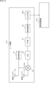
- FIG. 16 is a block diagram showing a specific example of a processing unit for point cloud data obtained by the FFT unit 51 in the radar device 11-2 of FIG. 12, which is the second embodiment of the radar device 11. As shown in FIG. In the figure, parts common to the radar device 11-2 of FIG. 12 are denoted by the same reference numerals, and detailed description thereof will be omitted.
- the radar device 11-2 of FIG. 16 includes a signal generation unit 21, a transmission antenna 22, a reception antenna 23, a mixing unit 24, an ADC 25, an FFT unit 51, a noise detection unit 71, a coordinate conversion unit 72, a data compression unit 73, and It has an output I/F section 26-2. Therefore, the radar device 11-2 of FIG. 16 has a signal generating section 21, a transmitting antenna 22, a receiving antenna 23, a mixing section 24, an ADC 25, an FFT section 51, and an output I/F section 26-2. 12 in common with the radar device 11-2. However, the radar device 11-2 of FIG. 16 differs from the radar device 11-2 of FIG. 12 in that it newly includes a noise detection unit 71, a coordinate conversion unit 72, and a data compression unit 73.
- the noise detection unit 71, the coordinate conversion unit 72, and the data compression unit 73 are specific examples of processing units for the point cloud data detected by the FFT unit 51.
- the radar device 11-2 may have one or more of the noise detection unit 71, the coordinate conversion unit 72, and the data compression unit 73, or may have none of them. may
- the noise detection unit 71 executes noise detection processing on the point cloud data from the FFT unit 51 .
- the point cloud data includes data of "Power” (hereinafter simply referred to as "intensity") corresponding to the radio wave intensity of the received radio wave.
- the noise detection unit 71 detects whether or not the intensity at each position and velocity is noise, and removes (or 0) intensity data at positions and velocities that are detected to be noise.
- CFAR Constant False. Alarm Rate
- CFAR Constant False. Alarm Rate
- CFAR noise detection by the noise detection unit 71
- CA-CFAR Cell Averaging Constant False Alarm Rate
- the noise detection unit 71 Each time one (one set) of point cloud data is supplied from the FFT unit 51, the noise detection unit 71 successively focuses on each position and velocity of the point cloud data as a target position and velocity.
- the noise detection unit 71 calculates a threshold based on the intensity at the position and speed in the surrounding range with respect to the position and speed of interest.
- the position and velocity in the peripheral range are positions and velocities that are greater than the first distance and less than or equal to the second distance from the position of interest and greater than the first velocity difference and less than or equal to the second velocity difference from the velocity of interest.
- the first distance is smaller than the second distance, and the first speed difference is smaller than the second speed difference.
- a value (average value of intensity, etc.) corresponding to the sum of intensities at positions and velocities in the surrounding range with respect to the position and velocity of interest is calculated.
- the noise detection unit 71 compares the intensity at the position and velocity of interest with a threshold, and determines that the intensity at the position and velocity of interest is not noise when the intensity at the position and velocity of interest is equal to or greater than the threshold, If it is less than the threshold, it is determined that the intensity at the target position and velocity is noise.
- data corresponding to noise is removed (invalidated) from the point cloud data detected by the FFT unit 51.
- FIG. The setting of such a threshold is not limited to a specific method such as CA-CFAR. For example, even if the threshold is set to a value according to the distance or a fixed value good.
- the coordinate transformation unit 72 coordinate-transforms each position and velocity of the point cloud data from the FFT unit 51 or the noise detection unit 71 from the polar coordinate system to the component value data in the rectangular coordinate system based on the distance and angle of each position. do. Note that only one of the position and velocity may be transformed into the orthogonal coordinate system.
- the coordinate conversion processing of the coordinate conversion section 72 may be performed prior to the noise detection processing of the noise detection section 71 .
- the data compression unit 73 performs data compression processing on the point cloud data from the FFT unit 51, the noise detection unit 71, or the coordinate conversion unit 72 to reduce the amount of data, and supplies it to the output IF unit 26-2. do.
- the output I/F unit 26-2 outputs the compressed point cloud data from the data compression unit 73 to the signal processing device 41-2, which is an external device, as the second type detection data. If the radar device 11-2 has the data compression unit 73, the signal processing device 41-2 has a decoding unit that decodes the compressed type 2 detection data from the radar device 11-2.
- any one of the noise detection unit 71, the coordinate conversion unit 72, and the data compression unit 73 described above is the radar device 11-1 according to the first embodiment in FIG. 12 or the third embodiment in FIG. may be arranged in the radar device 11-3 in the form of
- FIG. 17 illustrates an output data format (first form format) of detection data (second type detection data) that is point cloud data output by the output I/F unit 26-2 of the radar device 11-2 of FIG. It is a diagram of The first form format is at least the case where noise detection processing is not performed by the noise detection unit 71, and the second type detection data output by the output I/F unit 26-2 of the radar device 11-2 in FIG. corresponds to the output data format of
- the item “Frame” indicates that the detection data output from the output I/F unit 26-2 is divided into frames, which are basic structural units, as in FIG. .
- the item “Scan (mode)” under the item “Frame” indicates that the data areas divided for each frame are further divided into scan mode data areas, as in FIG.
- “Scan (mode)”, “Scan1”, “Scan2”, and “Scan3” indicate data areas of scan modes 1, 2, and 3, respectively. Note that the scan mode has already been described with reference to FIGS. 8 to 11, so description thereof will be omitted here.
- the item “Range” under the item “Scan (mode)” indicates that the data area divided by the scan mode is further divided into distance data areas.
- “Range”, “Range 1", “Range 2", ..., and “Range A” are data areas where point cloud data at corresponding distances indicates that "Range 1", “Range 2", ..., and “Range A” are assigned sections with different distances.
- the range of distances that can be scanned by the radar device 11-2 is divided into a plurality of (A) sections, and the respective sections are "Range 1", “Range 2", ..., and “Range A”. assigned to.
- the item “Velocity” under the item “Range” indicates that the data area divided by distance is further divided into the data area for velocity.
- “Velocity”, “Velocity 1", “Velocity 2", . indicates that “Velocity 1”, “Velocity 2”, . . . , and “Velocity B” are assigned different speed sections.
- the range of relative velocities between the radar device 11-2 and the object is divided into a plurality of (B) sections, and the respective sections are "Velocity 1", “Velocity 2", ..., and “Velocity B ”.
- the velocity obtained by the velocity FFT of the FFT unit 51 is the relative velocity in the direction connecting the position (point) where the object exists and the radar device 11-2.
- the velocity of the point cloud data is represented by the velocity in each of the XYZ axial directions (XYZ components) of the orthogonal coordinate system.
- the radar device 11-2 has the coordinate transformation unit 72 of FIG. is coordinate-transformed to calculate the velocity in each of the X, Y, and Z axes of the orthogonal coordinate system.
- the data area for the item "Velocity" may be hierarchized into data areas for each XYZ component.
- the item “Angle” under the item “Velocity” indicates that the data area divided by velocity is further divided into an angle data area.
- “Angle” indicates that "Angle 1", “Angle 2", ..., and “Angle C” are assigned different angular intervals.
- the range of angles that can be scanned by the radar device 11-2 is divided into a plurality of (C) sections, and the respective sections are "Angle 1", “Angle 2", ..., and "Angle C”. assigned to.
- the item “Data” under the item “Angle” indicates that the data area divided by angle is further divided into data areas for strength and acceleration data. Data of "Power” (strength) and “Acceleration” (acceleration) are arranged in this data area. Acceleration data may be calculated based on changes in velocity between frames, but may not be included in the point cloud data. Acceleration data may also be converted into component value data in an orthogonal coordinate system by the coordinate conversion unit 72 in FIG.
- the data structure of the point cloud data can be represented by the "Radar Cube” in Fig. 18.
- the vertical direction (vertical direction) represents “Range” (distance)
- the horizontal direction (horizontal direction) represents “Velocity” (velocity)
- the depth direction (front-rear direction) represents “Angle” (angle).
- represents “Range” (distance) is divided into sections corresponding to “Range 1", “Range 2", ..., and “Range A” in FIG. It is divided into intervals corresponding to “Velocity 1”, “Velocity 2”, . . . , and an interval corresponding to “Angle C”.
- the “Radar Cube” is divided into boxes each having a length of one section in the vertical direction, horizontal direction, and front-rear direction. acceleration) are associated with each other.
- the first form format shown in FIG. 17 is a format for sequentially outputting the intensity and acceleration data of each box of "Radar Cube" shown in FIG. 18 within one frame.
- FIG. 19 illustrates an output data format (second form format) of detection data (second type detection data) that is point cloud data output by the output I/F unit 26-2 of the radar device 11-2 of FIG. It is a diagram of The second form format corresponds at least to the output data format of the second type detection data output by the output I/F unit 26-2 when the noise detection unit 71 performs noise detection processing.
- the item "Detection” under the item “Scan (mode)” indicates that the data area divided by the scan mode is further divided into data areas for each detection point.
- the point cloud data relating to the object present at the detection point is position (distance and angle), velocity, strength, and acceleration data determined to be non-noise by the noise detection unit 71 in FIG.
- each box corresponds to a detection point, and the point cloud data on the object existing at the detection point specifies the box having an intensity judged to be non-noise among each box.
- Data (position and velocity data) and strength and acceleration data associated with the box. Boxes (detection points) with intensities determined to be non-noise are assigned to "Detection 1", “Detection 2", ... and "Detection X”.
- the item “Data” under the item “Detection” indicates that the data area divided for each detection point is further divided into data areas for distance, velocity, angle, strength, and acceleration.
- the data area of each detection point contains “Range bin” (distance), “Velocity bin” (velocity), “Angle bin” (angle), “Power” (strength), and “Acceleration” (acceleration) data. is placed.
- “Range bin” distance
- Velocity bin velocity
- Angle bin angle
- Power stress
- “Acceleration” acceleration
- the detection point Data of section numbers corresponding to speeds are arranged.
- the "Angle bin” (angle) data area when the range of angles that can be scanned by the radar device 11-2 is divided into a plurality of sections and each section is assigned a number, Section number data is arranged.
- the intensity and acceleration data of the detection point are arranged, respectively.
- FIG. 20 shows "Range bin” (distance), “Velocity bin” (velocity), “Angle bin” (angle), “Power” (strength), and “Acceleration bin” arranged in the data area of item “Data”. ” (acceleration) data.
- the data arranged in the respective data areas of "Detection 1", “Detection 2", . . . and “Detection X” are shown in the row direction.
- the “Detection 1” data area there are 10 “Range bin” data, 13 “Velocity bin” data, 5 “Angle bin” data, and 5 “Power bin” data.
- strength data is placed as -40.2 (dB)
- “Acceleration” (acceleration) data is placed as 0.12 (m/s).
- the information may be included as header information or the like in the second type detection data together with the point cloud data.
- the radar device 11-2 and the signal processing device 41-2 possess the structural information in advance so that the structural information can be included in the type 2 detection data. may be omitted.
- the number of data and the like may be limited so that the structure information in each frame is common.
- the number of detection points determined to be non-noise may vary from frame to frame.
- the data of the detection points with high intensity are preferentially included in the type 2 detection data so that the number of detection points included in the type 2 detection data is constant regardless of the frame. good too.
- the type 2 detection data may include arbitrary information such as time information indicating the time when the point cloud data was acquired.
- the present technology can also take the following configurations.
- a first interface for outputting, in a first output data format, RAW data immediately after sampling a signal received from a receiving antenna at a predetermined cycle and A/D converting the signal; a second interface for outputting point cloud data generated by performing predetermined signal processing on the RAW data in a second output data format; at least the first interface or the second interface among a third interface that outputs object recognition result data obtained by subjecting the point cloud data to object recognition processing in a third output data format.
- the first output data format includes IQ data as the RAW data.
- radar equipment The receiving antenna has a plurality of antennas, any one of (1) to (3) above, wherein the first output data format divides the RAW data obtained by sampling the received signal of each of the plurality of antennas for a predetermined period by the antenna; The radar device as described.
- the receiving antenna has a plurality of antennas, The radar apparatus according to (3), wherein the first output data format divides the RAW data obtained from each of the plurality of antennas for a plurality of cycles of the chirp signal by the antenna.
- the radar device according to (5), wherein data is divided by the antenna.
- the second interface outputs the point cloud data generated by performing FFT processing as the signal processing on the RAW data in the second output data format.
- the radar device according to any one of the above.
- the radar device according to any one of (1) to (9), wherein the second output data format includes position data indicating a position where an object exists.
- the second output data format uses data indicating the distance and direction of the position where the object exists as the position data.
- the radar device according to any one of (1) to (11), wherein the second output data format includes speed data indicating a relative speed of the position of the object with respect to the object.
- the radar device according to any one of (1) to (12) above, wherein the second output data format includes acceleration data indicating relative acceleration with respect to the object at a position where the object exists.
- the second output data format includes data indicating reception intensity of radio waves reflected at a position where an object exists.
- the second interface outputs the noise-removed point cloud data in a second output data format.
- the noise detection unit uses CFAR (Constant False. Alarm Rate) processing.
- the threshold is changed according to a position where the radio wave is reflected.
- the threshold to be compared with the received intensity of the radio wave reflected at the first position is calculated based on the received intensity of the radio wave reflected at positions around the first position.
- a first interface, a second interface, and a third interface wherein the first interface of the radar device samples a signal received from a receiving antenna at a predetermined period; output the RAW data immediately after A/D conversion with the first output data format, the second interface outputs point cloud data generated by performing predetermined signal processing on the RAW data in a second output data format;
- a data output method for a radar device wherein the third interface outputs object recognition result data obtained by subjecting the point cloud data to object recognition processing in a third output data format.
Landscapes
- Engineering & Computer Science (AREA)
- Radar, Positioning & Navigation (AREA)
- Remote Sensing (AREA)
- Computer Networks & Wireless Communication (AREA)
- Physics & Mathematics (AREA)
- General Physics & Mathematics (AREA)
- Radar Systems Or Details Thereof (AREA)
Priority Applications (5)
| Application Number | Priority Date | Filing Date | Title |
|---|---|---|---|
| KR1020237041159A KR20240072090A (ko) | 2021-09-29 | 2022-09-27 | 레이더 장치 및 레이더 장치의 데이터 출력 방법 |
| CN202280064134.2A CN117980776A (zh) | 2021-09-29 | 2022-09-27 | 雷达装置及雷达装置的数据输出方法 |
| US18/554,187 US20240192348A1 (en) | 2021-09-29 | 2022-09-27 | Radar device and data output method for radar device |
| EP22876227.4A EP4411416A4 (en) | 2021-09-29 | 2022-09-27 | RADAR DEVICE AND METHOD FOR OUTPUTTING DATA FROM A RADAR DEVICE |
| JP2023551526A JPWO2023054361A1 (https=) | 2021-09-29 | 2022-09-27 |
Applications Claiming Priority (2)
| Application Number | Priority Date | Filing Date | Title |
|---|---|---|---|
| JP2021159435 | 2021-09-29 | ||
| JP2021-159435 | 2021-09-29 |
Publications (1)
| Publication Number | Publication Date |
|---|---|
| WO2023054361A1 true WO2023054361A1 (ja) | 2023-04-06 |
Family
ID=85782760
Family Applications (1)
| Application Number | Title | Priority Date | Filing Date |
|---|---|---|---|
| PCT/JP2022/035948 Ceased WO2023054361A1 (ja) | 2021-09-29 | 2022-09-27 | レーダ装置、及び、レーダ装置のデータ出力方法 |
Country Status (6)
| Country | Link |
|---|---|
| US (1) | US20240192348A1 (https=) |
| EP (1) | EP4411416A4 (https=) |
| JP (1) | JPWO2023054361A1 (https=) |
| KR (1) | KR20240072090A (https=) |
| CN (1) | CN117980776A (https=) |
| WO (1) | WO2023054361A1 (https=) |
Cited By (1)
| Publication number | Priority date | Publication date | Assignee | Title |
|---|---|---|---|---|
| JP2025530621A (ja) * | 2023-07-24 | 2025-09-17 | 加特▲蘭▼微▲電▼子科技(上海)有限公司 | 目標検出方法、集積回路、センサ、装置及び媒体 |
Citations (5)
| Publication number | Priority date | Publication date | Assignee | Title |
|---|---|---|---|---|
| US20190285725A1 (en) * | 2018-03-14 | 2019-09-19 | Infineon Technologies Ag | Processing radar signals |
| US20200400810A1 (en) * | 2019-06-19 | 2020-12-24 | Samsung Electronics Co., Ltd. | Method and device with improved radar resolution |
| WO2021033479A1 (ja) * | 2019-08-20 | 2021-02-25 | パナソニックIpマネジメント株式会社 | 測距装置、情報処理方法、および情報処理装置 |
| JP2021042989A (ja) | 2019-09-06 | 2021-03-18 | 株式会社東芝 | レーダ装置 |
| US20210255279A1 (en) * | 2018-10-29 | 2021-08-19 | Texas Instruments Incorporated | Fmcw radar reduced power mode |
Family Cites Families (14)
| Publication number | Priority date | Publication date | Assignee | Title |
|---|---|---|---|---|
| US3651486A (en) * | 1968-11-06 | 1972-03-21 | Sixten Abrahamsson | Time interval generating apparatus |
| US8597034B2 (en) * | 2011-04-06 | 2013-12-03 | Hypertronics Corporation | Interface system having an interface with signal and ground traces connected to interface pins |
| EP2857860A4 (en) * | 2012-06-05 | 2015-06-17 | Panasonic Ip Man Co Ltd | SIGNAL PROCESSING DEVICE |
| US20170371492A1 (en) * | 2013-03-14 | 2017-12-28 | Rich IP Technology Inc. | Software-defined sensing system capable of responding to cpu commands |
| US10078131B2 (en) * | 2015-09-15 | 2018-09-18 | Texas Instruments Incorporated | Method and apparatus for FMCW radar processing |
| DE102016101901A1 (de) * | 2016-02-03 | 2017-08-03 | Deutsches Zentrum für Luft- und Raumfahrt e.V. | Fahrerassistenzsystem |
| US10942256B2 (en) * | 2017-06-05 | 2021-03-09 | Metawave Corporation | Intelligent metamaterial radar for target identification |
| DE102017117729B4 (de) * | 2017-08-04 | 2024-10-24 | Infineon Technologies Ag | Verteiltes Radarsystem |
| US11119186B2 (en) * | 2017-12-07 | 2021-09-14 | Texas Instruments Incorporated | Radar processing chain for frequency-modulated continuous wave radar systems |
| US10830880B2 (en) * | 2018-03-20 | 2020-11-10 | Panosense Inc. | Selecting LIDAR pulse detector depending on pulse type |
| US11448745B2 (en) * | 2018-06-22 | 2022-09-20 | Asahi Kasei Microdevices Corporation | Sensor device and system, and biometric sensing method and system |
| JP6735801B2 (ja) * | 2018-10-16 | 2020-08-05 | 三菱電機株式会社 | 物体認識装置およびこれを用いた車両制御装置並びに物体認識方法およびこれを用いた車両制御方法 |
| CN113365878B (zh) * | 2019-09-03 | 2025-06-06 | 北京航迹科技有限公司 | 自动驾驶系统的冗余结构 |
| JP6995258B2 (ja) * | 2019-12-05 | 2022-01-14 | 三菱電機株式会社 | レーダ信号処理器、レーダセンサシステム及び信号処理方法 |
-
2022
- 2022-09-27 KR KR1020237041159A patent/KR20240072090A/ko active Pending
- 2022-09-27 JP JP2023551526A patent/JPWO2023054361A1/ja active Pending
- 2022-09-27 US US18/554,187 patent/US20240192348A1/en active Pending
- 2022-09-27 WO PCT/JP2022/035948 patent/WO2023054361A1/ja not_active Ceased
- 2022-09-27 CN CN202280064134.2A patent/CN117980776A/zh active Pending
- 2022-09-27 EP EP22876227.4A patent/EP4411416A4/en active Pending
Patent Citations (5)
| Publication number | Priority date | Publication date | Assignee | Title |
|---|---|---|---|---|
| US20190285725A1 (en) * | 2018-03-14 | 2019-09-19 | Infineon Technologies Ag | Processing radar signals |
| US20210255279A1 (en) * | 2018-10-29 | 2021-08-19 | Texas Instruments Incorporated | Fmcw radar reduced power mode |
| US20200400810A1 (en) * | 2019-06-19 | 2020-12-24 | Samsung Electronics Co., Ltd. | Method and device with improved radar resolution |
| WO2021033479A1 (ja) * | 2019-08-20 | 2021-02-25 | パナソニックIpマネジメント株式会社 | 測距装置、情報処理方法、および情報処理装置 |
| JP2021042989A (ja) | 2019-09-06 | 2021-03-18 | 株式会社東芝 | レーダ装置 |
Non-Patent Citations (1)
| Title |
|---|
| MANO YOSHIHISA: "Mathematics and Programming Part 2 Practical Example Millimeter-Wave Radar Chapter 5 Mastering FFT through 1000 Trials and Errors Using Numerical Calculation Tools Instead of Textbooks Examples of mathematics becoming weapons…millimeter-wave radar.", INTERFACE, 1 September 2021 (2021-09-01), pages 90, XP093053759 * |
Cited By (2)
| Publication number | Priority date | Publication date | Assignee | Title |
|---|---|---|---|---|
| JP2025530621A (ja) * | 2023-07-24 | 2025-09-17 | 加特▲蘭▼微▲電▼子科技(上海)有限公司 | 目標検出方法、集積回路、センサ、装置及び媒体 |
| JP7847889B2 (ja) | 2023-07-24 | 2026-04-20 | 加特▲蘭▼微▲電▼子科技(上海)有限公司 | 目標検出方法、集積回路、センサ、装置及び媒体 |
Also Published As
| Publication number | Publication date |
|---|---|
| US20240192348A1 (en) | 2024-06-13 |
| CN117980776A (zh) | 2024-05-03 |
| JPWO2023054361A1 (https=) | 2023-04-06 |
| EP4411416A1 (en) | 2024-08-07 |
| EP4411416A4 (en) | 2024-12-25 |
| KR20240072090A (ko) | 2024-05-23 |
Similar Documents
| Publication | Publication Date | Title |
|---|---|---|
| Skaria et al. | Deep-Learning Methods for Hand-Gesture Recognition Using Ultra-Wideband Radar. | |
| CN112859033B (zh) | 目标探测的方法、装置及相关设备 | |
| EP1303767B1 (en) | Method and apparatus for recognising a radar target | |
| TWI646342B (zh) | 車載用雷達裝置 | |
| KR20200144862A (ko) | 레이더의 해상도 향상 방법 및 장치 | |
| Zheng et al. | Deep-neural-network-enabled vehicle detection using high-resolution automotive radar imaging | |
| CN111566506B (zh) | 用于确定对象的至少一个参数的方法和装置 | |
| CN114609626A (zh) | 一种车载毫米波雷达多目标检测方法 | |
| Li et al. | Wireless sensing with deep spectrogram network and primitive based autoregressive hybrid channel model | |
| KR102788287B1 (ko) | 레이더 신호로부터 표적 정보를 추출하는 방법 및 컴퓨터 판독가능 저장 매체 | |
| JP2019168255A (ja) | パルス圧縮レーダ装置及びそのレーダ信号処理方法 | |
| Roldan et al. | See further than cfar: a data-driven radar detector trained by lidar | |
| Qu et al. | Dynamic hand gesture classification based on multichannel radar using multistream fusion 1-D convolutional neural network | |
| Saarinen et al. | Radar waveform synthesis using generative adversarial networks | |
| WO2023054361A1 (ja) | レーダ装置、及び、レーダ装置のデータ出力方法 | |
| Wang et al. | A unified anti-jamming design in complex environments based on cross-modal fusion and intelligent decision-making | |
| Trinh et al. | Hand gesture recognition using mimo radar and lightweight convolutional neural network | |
| WO2022191197A1 (ja) | 物体位置検出装置及び方法 | |
| CN115754969B (zh) | 基于宽窄带结合和差单脉冲雷达智能目标识别系统及方法 | |
| CN209496136U (zh) | 基于mimo的毫米波雷达有轨电车防碰撞预警系统 | |
| JP2019200082A (ja) | 方位演算装置及び方位演算方法 | |
| Liu et al. | Radar-stda: A high-performance spatial-temporal denoising autoencoder for interference mitigation of fmcw radars | |
| Ren et al. | Research and Implementation of 77GHz Automotive Radar Target Detection Technology | |
| Zhu et al. | Trajectory-based physical target discrimination method for 4D mmWave vehicular radar | |
| JP2022180111A (ja) | 情報処理装置、及び、情報処理方法 |
Legal Events
| Date | Code | Title | Description |
|---|---|---|---|
| 121 | Ep: the epo has been informed by wipo that ep was designated in this application |
Ref document number: 22876227 Country of ref document: EP Kind code of ref document: A1 |
|
| WWE | Wipo information: entry into national phase |
Ref document number: 18554187 Country of ref document: US |
|
| WWE | Wipo information: entry into national phase |
Ref document number: 2023551526 Country of ref document: JP |
|
| WWE | Wipo information: entry into national phase |
Ref document number: 202280064134.2 Country of ref document: CN |
|
| NENP | Non-entry into the national phase |
Ref country code: DE |
|
| ENP | Entry into the national phase |
Ref document number: 2022876227 Country of ref document: EP Effective date: 20240429 |