WO2023054303A1 - 二次電池用正極および二次電池 - Google Patents
二次電池用正極および二次電池 Download PDFInfo
- Publication number
- WO2023054303A1 WO2023054303A1 PCT/JP2022/035822 JP2022035822W WO2023054303A1 WO 2023054303 A1 WO2023054303 A1 WO 2023054303A1 JP 2022035822 W JP2022035822 W JP 2022035822W WO 2023054303 A1 WO2023054303 A1 WO 2023054303A1
- Authority
- WO
- WIPO (PCT)
- Prior art keywords
- positive electrode
- active material
- electrode active
- region
- mixture layer
- Prior art date
- Legal status (The legal status is an assumption and is not a legal conclusion. Google has not performed a legal analysis and makes no representation as to the accuracy of the status listed.)
- Ceased
Links
Images

Classifications
-
- H—ELECTRICITY
- H01—ELECTRIC ELEMENTS
- H01M—PROCESSES OR MEANS, e.g. BATTERIES, FOR THE DIRECT CONVERSION OF CHEMICAL ENERGY INTO ELECTRICAL ENERGY
- H01M4/00—Electrodes
- H01M4/02—Electrodes composed of, or comprising, active material
- H01M4/13—Electrodes for accumulators with non-aqueous electrolyte, e.g. for lithium-accumulators; Processes of manufacture thereof
-
- H—ELECTRICITY
- H01—ELECTRIC ELEMENTS
- H01M—PROCESSES OR MEANS, e.g. BATTERIES, FOR THE DIRECT CONVERSION OF CHEMICAL ENERGY INTO ELECTRICAL ENERGY
- H01M4/00—Electrodes
- H01M4/02—Electrodes composed of, or comprising, active material
- H01M4/13—Electrodes for accumulators with non-aqueous electrolyte, e.g. for lithium-accumulators; Processes of manufacture thereof
- H01M4/131—Electrodes based on mixed oxides or hydroxides, or on mixtures of oxides or hydroxides, e.g. LiCoOx
-
- H—ELECTRICITY
- H01—ELECTRIC ELEMENTS
- H01M—PROCESSES OR MEANS, e.g. BATTERIES, FOR THE DIRECT CONVERSION OF CHEMICAL ENERGY INTO ELECTRICAL ENERGY
- H01M10/00—Secondary cells; Manufacture thereof
- H01M10/05—Accumulators with non-aqueous electrolyte
- H01M10/052—Li-accumulators
-
- H—ELECTRICITY
- H01—ELECTRIC ELEMENTS
- H01M—PROCESSES OR MEANS, e.g. BATTERIES, FOR THE DIRECT CONVERSION OF CHEMICAL ENERGY INTO ELECTRICAL ENERGY
- H01M10/00—Secondary cells; Manufacture thereof
- H01M10/05—Accumulators with non-aqueous electrolyte
- H01M10/056—Accumulators with non-aqueous electrolyte characterised by the materials used as electrolytes, e.g. mixed inorganic/organic electrolytes
- H01M10/0564—Accumulators with non-aqueous electrolyte characterised by the materials used as electrolytes, e.g. mixed inorganic/organic electrolytes the electrolyte being constituted of organic materials only
- H01M10/0566—Liquid materials
-
- H—ELECTRICITY
- H01—ELECTRIC ELEMENTS
- H01M—PROCESSES OR MEANS, e.g. BATTERIES, FOR THE DIRECT CONVERSION OF CHEMICAL ENERGY INTO ELECTRICAL ENERGY
- H01M4/00—Electrodes
- H01M4/02—Electrodes composed of, or comprising, active material
- H01M4/36—Selection of substances as active materials, active masses, active liquids
-
- H—ELECTRICITY
- H01—ELECTRIC ELEMENTS
- H01M—PROCESSES OR MEANS, e.g. BATTERIES, FOR THE DIRECT CONVERSION OF CHEMICAL ENERGY INTO ELECTRICAL ENERGY
- H01M4/00—Electrodes
- H01M4/02—Electrodes composed of, or comprising, active material
- H01M4/36—Selection of substances as active materials, active masses, active liquids
- H01M4/362—Composites
- H01M4/364—Composites as mixtures
-
- H—ELECTRICITY
- H01—ELECTRIC ELEMENTS
- H01M—PROCESSES OR MEANS, e.g. BATTERIES, FOR THE DIRECT CONVERSION OF CHEMICAL ENERGY INTO ELECTRICAL ENERGY
- H01M4/00—Electrodes
- H01M4/02—Electrodes composed of, or comprising, active material
- H01M4/36—Selection of substances as active materials, active masses, active liquids
- H01M4/48—Selection of substances as active materials, active masses, active liquids of inorganic oxides or hydroxides
- H01M4/52—Selection of substances as active materials, active masses, active liquids of inorganic oxides or hydroxides of nickel, cobalt or iron
- H01M4/525—Selection of substances as active materials, active masses, active liquids of inorganic oxides or hydroxides of nickel, cobalt or iron of mixed oxides or hydroxides containing iron, cobalt or nickel for inserting or intercalating light metals, e.g. LiNiO2, LiCoO2 or LiCoOxFy
-
- H—ELECTRICITY
- H01—ELECTRIC ELEMENTS
- H01M—PROCESSES OR MEANS, e.g. BATTERIES, FOR THE DIRECT CONVERSION OF CHEMICAL ENERGY INTO ELECTRICAL ENERGY
- H01M4/00—Electrodes
- H01M4/02—Electrodes composed of, or comprising, active material
- H01M2004/021—Physical characteristics, e.g. porosity, surface area
-
- H—ELECTRICITY
- H01—ELECTRIC ELEMENTS
- H01M—PROCESSES OR MEANS, e.g. BATTERIES, FOR THE DIRECT CONVERSION OF CHEMICAL ENERGY INTO ELECTRICAL ENERGY
- H01M4/00—Electrodes
- H01M4/02—Electrodes composed of, or comprising, active material
- H01M2004/026—Electrodes composed of, or comprising, active material characterised by the polarity
- H01M2004/028—Positive electrodes
-
- Y—GENERAL TAGGING OF NEW TECHNOLOGICAL DEVELOPMENTS; GENERAL TAGGING OF CROSS-SECTIONAL TECHNOLOGIES SPANNING OVER SEVERAL SECTIONS OF THE IPC; TECHNICAL SUBJECTS COVERED BY FORMER USPC CROSS-REFERENCE ART COLLECTIONS [XRACs] AND DIGESTS
- Y02—TECHNOLOGIES OR APPLICATIONS FOR MITIGATION OR ADAPTATION AGAINST CLIMATE CHANGE
- Y02E—REDUCTION OF GREENHOUSE GAS [GHG] EMISSIONS, RELATED TO ENERGY GENERATION, TRANSMISSION OR DISTRIBUTION
- Y02E60/00—Enabling technologies; Technologies with a potential or indirect contribution to GHG emissions mitigation
- Y02E60/10—Energy storage using batteries
Definitions
- the present disclosure relates to secondary batteries, and in particular to improvements in positive electrodes used in secondary batteries.
- Secondary batteries especially lithium-ion secondary batteries, have high output and high energy density, so they are expected to be used as power sources for small consumer applications, power storage devices, and electric vehicles.
- Patent Document 1 a positive electrode current collector and a positive electrode mixture layer containing a positive electrode active material and provided on the surface of the positive electrode current collector are provided.
- No. 1 positive electrode active material and a second positive electrode active material having a compressive strength of 250 MPa or less have been proposed.
- the positive electrode mixture layer is divided into the first region and the second region having the same thickness, by varying the content ratio of the first positive electrode active material and the second positive electrode active material between the first region and the second region, A secondary battery using this positive electrode for a secondary battery can achieve both high energy density and high cycle characteristics.
- one aspect of the present disclosure includes a positive electrode current collector, and a positive electrode mixture layer containing a positive electrode active material and provided on the surface of the positive electrode current collector, wherein the positive electrode mixture layer is A first positive electrode active material having a compressive strength of 400 MPa or less and a second positive electrode active material having a compressive strength lower than that of the first positive electrode active material are included, and the positive electrode mixture layer is separated from the first region and the second positive electrode active material having the same thickness. When divided into two regions, more of the first positive electrode active material is contained in the first region than in the second region, and more of the second positive electrode active material is contained in the second region than in the first region. It relates to positive electrodes for secondary batteries, which are often included.
- Another aspect of the present disclosure relates to a secondary battery including the positive electrode for a secondary battery, a separator, a negative electrode facing the positive electrode for a secondary battery via the separator, and an electrolytic solution.
- FIG. 1 is a cross-sectional view schematically showing the structure of a positive electrode for a secondary battery according to one embodiment of the present disclosure
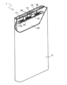
- FIG. 1 is a schematic perspective view of a partially cutaway secondary battery according to an embodiment of the present disclosure
- the present disclosure encompasses a combination of matters described in two or more claims arbitrarily selected from the multiple claims described in the attached claims. In other words, as long as there is no technical contradiction, the matters described in two or more claims arbitrarily selected from the multiple claims described in the attached claims can be combined.
- containing or “including” include expressions that include “containing (or including),” “consisting essentially of,” and “consisting of.” is.
- Secondary batteries include at least nonaqueous electrolyte secondary batteries such as lithium ion batteries and lithium metal secondary batteries.
- a positive electrode for a secondary battery includes a positive electrode current collector and a positive electrode mixture layer containing a positive electrode active material and provided on the surface of the positive electrode current collector.
- the positive electrode mixture layer includes a first positive electrode active material having a compressive strength of 400 MPa or less and a second positive electrode active material having a lower compressive strength than the first positive electrode active material.
- the first positive electrode active material is contained more in the first region than in the second region
- the second positive electrode active material is contained more in the second region than in the first region. That is, the first positive electrode active material and the second positive electrode active material have concentration distributions in the thickness direction of the positive electrode mixture layer.
- the concentration of the first positive electrode active material is high in the first region
- the concentration of the second positive electrode active material is high in the second region.
- concentration here means the content rate on a mass basis.
- the first region may not substantially contain the second positive electrode active material.
- the second region may not substantially contain the first positive electrode active material.
- the first positive electrode active material is difficult to expand and contract, and is difficult to be crushed. Therefore, when the first positive electrode active material is used as the positive electrode active material, expansion and contraction of the positive electrode active material due to charging and discharging are suppressed, and crushing of the positive electrode active material is suppressed. As a result, it is thought that the generation of new surfaces that cause electrochemical reactions including side reactions is suppressed, and the cycle retention rate is improved. However, there is a limit to improving the capacity in order to obtain a high energy density battery.
- the positive electrode material mixture layer is generally rolled during fabrication of the positive electrode.
- the positive electrode active materials are brought closer to each other and partially crushed, and the fine particles generated by the crushing can fill the gaps between the active materials. Thereby, a higher energy density can be obtained.
- the first positive electrode active material is difficult to crush, it is difficult to obtain a high energy density battery using only the first positive electrode active material.
- the second positive electrode active material is more easily compressed than the first positive electrode active material. More specifically, during rolling, fine particles generated by crushing the second positive electrode active material are filled in gaps between the second positive electrode active materials, or the second positive electrode active material is deformed. By filling the gaps between the second positive electrode active materials by using the second positive electrode active material, the apparent volume is likely to be reduced. Therefore, it is easy to obtain a secondary battery with a high energy density.
- the compression makes it difficult for the electrolytic solution to permeate deep into the positive electrode mixture layer on the positive electrode current collector side, and the circulation of the liquid may decrease. As a result, it is difficult to obtain a battery with high cycle characteristics.
- the positive electrode mixture layer has the first region and the second region in which the content ratios of the first positive electrode active material and the second positive electrode active material are different, the pressure applied to the positive electrode mixture layer during compression is dispersed, The active material density in the positive electrode mixture layer can be increased appropriately. This results in a high energy density battery. Furthermore, this battery has good liquid circulation and excellent cycle characteristics.
- Both the compressive strengths of the first positive electrode active material and the second positive electrode active material are 400 MPa or less.
- the first region may contain a second positive electrode active material.
- the second region may contain the first positive electrode active material.
- the first positive electrode active material and the second positive electrode active material can be distinguished from each other by differences in shape, size, and morphology in a cross-sectional SEM photograph of the surface of the positive electrode mixture layer, or by composition analysis (elemental mapping). In that case, the compressive strength is an average value for 20 or more positive electrode active material particles.
- the compressive strength is measured for each particle of the positive electrode active material in the positive electrode mixture layer, and the compression is When the strength distribution is obtained, two peaks corresponding to the first positive electrode active material and the second positive electrode active material appear in the compressive strength distribution.
- the first positive electrode active material and the second positive electrode active material are made of the same material, or when it is difficult to distinguish them from SEM photographs, they can be analyzed separately. Identify the contours of the particles of the positive electrode active material in the SEM photograph.
- the compressive strength is obtained by the method described later, and the distribution of the compressive strength is obtained.
- the compressive strength distribution has two peaks in the region of 400 MPa or less, the presence of the first positive electrode active material and the second positive electrode active material is presumed.
- the compressive strength (minimum compressive strength) at which the distribution is minimized between the two peaks is determined, and the active material having a compressive strength of 400 MPa or less at the minimum compressive strength or more is used as the first positive electrode active material, and the minimum compressive strength or more and 400 MPa or less.
- An active material having a compressive strength less than the minimum compressive strength is defined as a second positive electrode active material, and the average value of the compressive strengths of the active materials having a compressive strength less than the minimum compressive strength is defined as the compressive strength of the second positive electrode active material.
- the compressive strength of both the first positive electrode active material and the second positive electrode active material is 400 MPa or less, the positive electrode mixture layer as a whole is easily compressed, and a high energy density battery is easily obtained.
- the positive electrode mixture layer has, for example, a laminated structure of a first layer containing a large amount of the first positive electrode active material and a second layer containing a large amount of the second positive electrode active material.
- the thickness of the first layer and the thickness of the second layer do not necessarily have to be the same. If there is a difference in the concentration of the first positive electrode active material and the concentration of the second positive electrode active material between the first layer and the second layer, the entire first layer and the second layer are formed to have the same thickness as the first region and the second layer. When divided into two regions, a difference occurs in the concentration of the first positive electrode active material and the concentration of the second positive electrode active material between the first region and the second region.
- the compressive strength of the first positive electrode active material is large, for example, exceeding 400 MPa, and the difference in compressive strength between the first positive electrode active material and the second positive electrode active material is too large, A large compressive force is applied to , and the positive electrode active material (for example, the second positive electrode active material) may be crushed at the boundary between the first layer and the second layer to fill the gaps between the particles. As a result, the flow of the electrolytic solution is hindered, and the cycle characteristics may deteriorate.
- the compressive strengths of the first positive electrode active material and the second positive electrode active material are both 400 MPa or less, so the difference in compressive strength between the first positive electrode active material and the second positive electrode active material is It is small and can maintain high cycle characteristics.
- a difference in compressive strength between the first positive electrode active material and the second positive electrode active material may be, for example, 50 MPa or more and less than 150 MPa.
- the compressive strength of the second positive electrode active material may be 150 MPa or less.
- the compressive strength of the first positive electrode active material may be 150 MPa or more, or may be 200 MPa or more.
- the compressive strength of the second positive electrode active material is, for example, 3/4 times or less the compressive strength of the first positive electrode active material (in other words, the compressive strength of the first positive electrode active material is 1.33 times the compressive strength of the second positive electrode active material. times or more).
- the compressive strength is the compressive strength per primary particle in the case of primary particles, and the compressive strength per secondary particle in the case of secondary particles.
- d is the particle diameter of the secondary particles or primary particles, and the secondary particle diameter is used to calculate the compressive strength of the secondary particles, and the primary particle diameter is used to calculate the compressive strength of the primary particles. . Observe with a CCD or the like, and measure the compressive strength of the selected primary particles or secondary particles with a microcompression tester.
- the second region may be closer to the positive current collector than the first region. That is, the first positive electrode active material may be contained more on the surface side of the positive electrode than on the positive electrode current collector side, and the second positive electrode active material may be contained more on the positive electrode current collector side than on the positive electrode surface side. .
- the first region containing a large amount of the first positive electrode active material having high compressive strength is located on the surface layer side of the positive electrode, the surface of the positive electrode may be blocked when the positive electrode is expanded and compressed due to discharge.
- the electrolyte can penetrate to the second region through the gaps interposed between the first positive electrode active materials. Therefore, the liquid circulation property is good, and the cycle maintenance rate can be improved.
- the first positive electrode active material may be, for example, non-aggregated particles (composite oxide particles) or aggregated particles (composite oxide particles). preferable.
- the second positive electrode active material may be aggregated particles (composite oxide particles). Both the first positive electrode active material and the second positive electrode active material are preferably aggregated particles (composite oxide particles).
- Composite oxide particles in a non-aggregated state include the case where the composite oxide particles are separated as one primary particle, and the number of primary particles is several to ten and several (specifically, 2 to 19). Including huddled states.
- Non-agglomerated composite oxide particles are difficult to crush and have excellent cycle characteristics because the increase in surface area is suppressed.
- the compressive force applied to the first positive electrode mixture layer is alleviated by the second region containing a large amount of the second positive electrode active material, and a high cycle retention rate can be achieved even when a large compressive force is applied to the positive electrode mixture layer. It is also easy to increase the density of the positive electrode mixture layer by increasing the pressure during rolling.
- Composite oxide particles in an aggregated state refer to a state in which a plurality of primary particles (specifically, 20 or more) of composite oxide particles gather together to form secondary particles.
- the aggregated composite oxide particles may consist of 20 to 5,000,000 (more generally 10,000 to 5,000,000) primary particles.
- Aggregated complex oxide particles have a small primary particle size and are easily crushed, and thus have a large reaction area with the electrolytic solution. Therefore, it is easy to obtain a high capacity.
- side reactions with the electrolyte tend to increase, and the cycle retention rate may decrease due to repeated charging and discharging.
- the concentrations of the first positive electrode active material and the second positive electrode active material are distributed between the first region and the second region, and the first positive electrode active material is more concentrated than the second region.
- the particle size of the primary particles contained in the aggregated particles may be, for example, 500 nm or less, or may be in the range of 200 nm to 500 nm.
- the particle size of the primary particles can be obtained by observing the grain boundaries of the primary particles based on the SEM photograph of the aggregated composite oxide particles.
- the outline is specified from the grain boundaries of a plurality of (for example, 20 or more) selected primary particles, the major axis of each primary particle is obtained from the outline, and the average value of the major axis is taken as the particle size of the primary particle.
- the particle size of the aggregated particles may be in the range of 5 ⁇ m to 20 ⁇ m, or 5 ⁇ m to 15 ⁇ m. In this case, a high cycle maintenance rate is likely to be achieved.
- the particle size of the secondary particles is obtained by observing the grain boundaries of the secondary particles based on the SEM photograph of the composite oxide particles.
- the outline is specified from the grain boundaries of a plurality of (for example, 20 or more) selected secondary particles, the major axis of each primary particle is obtained from the outline, and the average value of the major axis is taken as the particle size of the secondary particle.
- the first region may contain a second positive electrode active material and/or a positive electrode active material having a compressive strength exceeding 400 MPa.
- the content of the first positive electrode active material in the first region may be 50% by mass or more, or may be 70% by mass or more.
- the second region may contain the first positive electrode active material and/or the positive electrode active material having a compressive strength exceeding 400 MPa.
- the content of the second positive electrode active material in the second region may be 50% by mass or more, or may be 70% by mass or more.
- the particle size of the first positive electrode active material and the second positive electrode active material and the content in the positive electrode mixture layer can be obtained by image analysis of the SEM photograph of the cross section of the positive electrode by the following method.
- the area surrounded by the contours is obtained.
- the diameter of a circle (equivalent circle) having the same area as the contour area of the first positive electrode active material particle is obtained and taken as the particle diameter of each particle i, and the volume of a sphere having the same diameter is regarded as the volume Vi of each particle i.
- the diameter of a circle (equivalent circle) having the same area as the contour area of the second positive electrode active material particle is obtained, and the particle size of each particle j is determined.
- the density of the first positive electrode active material is ⁇ 1, and the density of the second positive electrode active material is ⁇ 2.
- the content C1 of the first positive electrode active material in the predetermined region is obtained by dividing Vi or Vj for each particle existing in the predetermined region of the cross-sectional SEM image of the first positive electrode mixture layer. By deriving, it is obtained by the following formula.
- the content C2 of the second positive electrode active material in the predetermined region is obtained by the following formula by deriving Vi or Vj for each particle present in the predetermined region of the cross-sectional SEM image of the second positive electrode mixture layer. be done.
- C1 ⁇ i ⁇ 1Vi /( ⁇ i ⁇ 1Vi + ⁇ j ⁇ 2Vj )
- C2 ⁇ j ⁇ 2Vj /( ⁇ i ⁇ 1Vi + ⁇ j ⁇ 2Vj )
- a plurality of (for example, 20 or more) small regions are arbitrarily selected in the first region or the second region, and C1 is selected in each small region. It may be derived by calculating and obtaining an average value.
- a plurality of (for example, 20 or more) small regions are arbitrarily selected in the first region or the second region, and each small region may be derived by calculating C2 in and calculating the average value.
- C1 and C2 may be C1>C2 in the first region and C1 ⁇ C2 in the second region. More specifically, C1 may be 0.5 or more, 0.7 or more, or 0.8 or more in the first region. C2 may be 0.5 or more, 0.7 or more, or 0.8 or more in the second region.
- FIG. 1 is a cross-sectional view schematically showing the structure of the positive electrode for a secondary battery according to this embodiment.
- the secondary battery positive electrode 20 includes a positive electrode current collector 21 and positive electrode mixture layers 22 (22a, 22b).
- the positive electrode mixture layers 22 can be formed on both main surfaces of the positive electrode current collector 21 .
- FIG. 1 shows the positive electrode mixture layer 22 formed on the main surface A1 of the positive electrode current collector 21, and the positive electrode mixture layer formed on the main surface A2 of the positive electrode current collector 21 opposite to the main surface A1. is omitted.
- the positive electrode mixture layer 22 is divided into a first region R1 and a second region R2 each having the same thickness. That is, each of the first region R1 and the second region R2 has a thickness half the thickness of the positive electrode mixture layer 22 .
- the first positive electrode mixture layer 22a is formed in the first region R1
- the second positive electrode mixture layer 22b is formed in the second region R2.
- the second positive electrode mixture layer 22b is interposed between the positive electrode current collector 21 and the first positive electrode mixture layer 22a. That is, the first positive electrode mixture layer 22a is on the surface side of the positive electrode and faces the negative electrode.
- the second positive electrode mixture layer 22b is located on the positive electrode current collector 21 side and faces the main surface A1 of the positive electrode current collector 21 .
- the first positive electrode mixture layer 22a contains the first positive electrode active material 23 having a compressive strength of 400 MPa or less.
- the second positive electrode mixture layer 22 b includes a second positive electrode active material 24 having a lower compressive strength than the first positive electrode active material 23 .
- the first positive electrode active material 23 and the second positive electrode active material 24 may be, for example, non-aggregated particles. In FIG. 1, the boundaries between the primary particles in the first positive electrode active material 23 and the second positive electrode active material 24 are indicated by dashed lines.
- the second positive electrode active material 24 may be contained in the first positive electrode mixture layer 22a. However, the content ratio of the second positive electrode active material 24 contained in the first positive electrode mixture layer 22a is smaller than the content ratio of the second positive electrode active material 24 contained in the second positive electrode mixture layer 22b. Similarly, the first positive electrode active material 23 may be included in the second positive electrode mixture layer 22b. However, the content ratio of the first positive electrode active material 23 contained in the second positive electrode mixture layer 22b is smaller than the content ratio of the first positive electrode active material 23 contained in the first positive electrode mixture layer 22a.
- the second positive electrode mixture layer 22b formed in the second region is closer to the positive electrode current collector 21 than the first positive electrode mixture layer 22a formed in the first region.
- the positional relationship between the first positive electrode mixture layer 22a and the second positive electrode mixture layer 22b may be reversed. That is, the first positive electrode mixture layer 22a may be closer to the positive electrode current collector 21 than the second positive electrode mixture layer 22b.
- both the first positive electrode mixture layer 22a and the second positive electrode mixture layer 22b have a thickness half the thickness of the entire positive electrode mixture layer 22, and the first positive electrode mixture layer 22a and the second positive electrode mixture layer 22b
- the boundary with the positive electrode mixture layer 22b coincides with the boundary between the first region and the second region.
- the first positive electrode mixture layer 22a may be formed thicker than the second positive electrode mixture layer 22b, or conversely, the second positive electrode mixture layer 22b may be formed thicker than the first positive electrode mixture layer 22a. good.
- the content ratios of the first positive electrode active material 23 and the second positive electrode active material 24 between the first positive electrode mixture layer 22a and the second positive electrode mixture layer 22b are respectively
- An intermediate layer having a range between the content ratio and the content ratio in the second positive electrode mixture layer 22b may be interposed.
- the positive electrode 20 described above can be manufactured by preparing a plurality of kinds of positive electrode slurries having different content ratios of the second positive electrode active material 24 to the first positive electrode active material 23 and applying them to the surface of the positive electrode current collector 21 .
- a secondary battery includes, for example, a positive electrode, a negative electrode, an electrolytic solution, and a separator as described below.
- the positive electrode includes a positive electrode current collector and a positive electrode mixture layer formed on the surface of the positive electrode current collector and containing a positive electrode active material.
- a positive electrode for a secondary battery having the first positive electrode mixture layer and the second positive electrode mixture layer is used.
- a positive electrode slurry in which a positive electrode mixture containing a positive electrode active material, a binder, etc. is dispersed in a dispersion medium is applied to the surface of the positive electrode current collector. It can be formed by coating and drying. The dried coating film may be rolled if necessary.
- the positive electrode material mixture layer may be formed on one surface of the positive electrode current collector, or may be formed on both surfaces.
- the positive electrode active material (the first positive electrode active material and the second positive electrode active material), a lithium-containing composite oxide having a layered rock salt crystal structure containing lithium and a transition metal can be used.
- the lithium-containing composite oxide is, for example, Li a Ni 1-xy Co x M y O 2 (where 0 ⁇ a ⁇ 1.2, 0 ⁇ x ⁇ 0.1, 0 ⁇ y ⁇ 0.1, 0 ⁇ x+y ⁇ 0.1, and M is selected from the group consisting of Na, Mg, Sc, Y, Mn, Fe, Cu, Zn, Al, Cr, Pb, Sb and B at least one type.) may be used.
- Al may be included as M from the viewpoint of the stability of the crystal structure.
- the value a which indicates the molar ratio of lithium, increases or decreases due to charging and discharging.
- Specific examples of such composite oxides include lithium-nickel-cobalt-aluminum composite oxides (LiNi 0.88 Co 0.09 Al 0.03 O 2 , LiNi 0.9 Co 0.05 Al 0.05 O 2 , LiNi0.91Co0.06Al0.03O2 , etc. ) .
- the first positive electrode active material and the second positive electrode active material have different compressive strengths as described above. However, the material and composition may be the same or different between the first positive electrode active material and the second positive electrode active material.
- a predetermined amount of a positive electrode active material other than the first positive electrode active material and the second positive electrode active material (that is, an active material having a compressive strength exceeding 400 MPa) may be contained in the positive electrode mixture layer.
- a method for producing a lithium-containing composite oxide will be described below, taking a composite oxide mainly composed of lithium, nickel, and cobalt as an example.
- a method for producing a lithium-containing composite oxide includes, for example, a composite hydroxide synthesis step for obtaining a Ni, Co, Al composite hydroxide or a Ni, Co, Mn composite hydroxide, etc., and a composite hydroxide and a lithium compound. and a sintering step of sintering the raw material mixture to obtain composite oxide particles.
- the composite hydroxide synthesis step for example, by a coprecipitation method, while stirring a metal salt solution containing Ni, Co, Al (or Mn), etc., an alkaline solution such as sodium hydroxide is added dropwise to adjust the pH to alkaline.
- Ni, Co, Al composite hydroxide or Ni, Co, Mn composite hydroxide is precipitated (coprecipitated) by adjusting to the side (for example, 8.5 to 11.5).
- the composite hydroxide synthesizing step may include an aging step in which the composite hydroxide is left as it is in the reaction solution after precipitation of the composite hydroxide. This makes it easier to obtain composite oxide particles with greater compressive strength.
- a raw material mixture is obtained by mixing the composite hydroxide with lithium compounds such as lithium hydroxide, lithium carbonate, and lithium nitrate.
- lithium compounds such as lithium hydroxide, lithium carbonate, and lithium nitrate.
- the mixing ratio of the composite hydroxide and the lithium compound is such that the molar ratio of metal elements (Ni + Co + Al or Mn): Li is 1.0: 1.02 to 1.0: The ratio may be in the range of 1.2.
- the raw material mixture is fired in an oxygen atmosphere to obtain composite oxide particles. It is also possible to control the compressive strength of the finally obtained composite oxide particles by adjusting the firing temperature of the raw material mixture.
- the firing temperature of the raw material mixture may be in the range of 750° C. or more and 1100° C. or less, for example.
- the firing temperature is preferably 20 hours to 150 hours, more preferably 20 hours to 100 hours.
- the shape and thickness of the positive electrode current collector can be selected from the shape and range according to the negative electrode current collector.
- Examples of materials for the positive electrode current collector include stainless steel, aluminum, aluminum alloys, and titanium.
- the negative electrode may include, for example, at least a negative electrode current collector and a negative electrode active material layer formed on the surface of the negative electrode current collector.
- the negative electrode active material layer can be formed, for example, by applying a negative electrode slurry in which a negative electrode mixture containing a negative electrode active material, a binder and the like is dispersed in a dispersion medium on the surface of the negative electrode current collector and drying the slurry. The dried coating film may be rolled if necessary. That is, the negative electrode active material may be a mixture layer. Also, a lithium metal foil or a lithium alloy foil may be attached to the negative electrode current collector.
- the negative electrode active material layer may be formed on one surface of the negative electrode current collector, or may be formed on both surfaces.
- the negative electrode active material layer contains the negative electrode active material as an essential component, and may contain a binder, a conductive agent, a thickener, etc. as optional components. Known materials can be used as the binder, conductive agent, and thickener.
- the negative electrode active material includes materials that electrochemically absorb and release lithium ions, lithium metal, and/or lithium alloys.
- Materials that electrochemically occlude and release lithium ions include carbon materials, silicon-containing materials, and alloy materials.
- carbon materials include graphite, graphitizable carbon (soft carbon), and non-graphitizable carbon (hard carbon). Among them, graphite is preferable because it has excellent charging/discharging stability and low irreversible capacity.
- Examples of alloy materials include those containing at least one metal capable of forming an alloy with lithium, such as silicon, tin, silicon alloys, tin alloys, and silicon compounds. Silicon oxide, tin oxide, or the like in which these are combined with oxygen may also be used.
- Materials containing silicon or alloy-based materials include, for example, silicon oxide and alloy compounds containing silicon, but are not particularly limited.
- a non-porous conductive substrate metal foil, etc.
- a porous conductive substrate meh body, net body, punching sheet, etc.
- materials for the negative electrode current collector include stainless steel, nickel, nickel alloys, copper, and copper alloys.
- the electrolyte contains a solvent and a solute dissolved in the solvent.
- a solute is an electrolyte salt that ionically dissociates in the electrolyte.
- Solutes can include, for example, lithium salts.
- Components of electrolytes other than solvents and solutes are additives.
- the electrolyte may contain various additives.
- aqueous solvent or a non-aqueous solvent is used as the solvent.
- non-aqueous solvents include cyclic carbonates, chain carbonates, cyclic carboxylates, chain carboxylates, and the like.
- Cyclic carbonates include propylene carbonate (PC), ethylene carbonate (EC), vinylene carbonate (VC) and the like.
- Chain carbonates include diethyl carbonate (DEC), ethyl methyl carbonate (EMC), dimethyl carbonate (DMC) and the like.
- cyclic carboxylic acid esters include ⁇ -butyrolactone (GBL) and ⁇ -valerolactone (GVL).
- Chain carboxylic acid esters include methyl acetate, ethyl acetate, propyl acetate, methyl propionate (MP), ethyl propionate (EP) and the like.
- the non-aqueous solvent may be used singly or in combination of two or more.
- non-aqueous solvents include cyclic ethers, chain ethers, nitriles such as acetonitrile, and amides such as dimethylformamide.
- cyclic ethers examples include 1,3-dioxolane, 4-methyl-1,3-dioxolane, tetrahydrofuran, 2-methyltetrahydrofuran, propylene oxide, 1,2-butylene oxide, 1,3-dioxane, 1,4- dioxane, 1,3,5-trioxane, furan, 2-methylfuran, 1,8-cineol, crown ether and the like.
- linear ethers examples include 1,2-dimethoxyethane, dimethyl ether, diethyl ether, dipropyl ether, diisopropyl ether, dibutyl ether, dihexyl ether, ethyl vinyl ether, butyl vinyl ether, methylphenyl ether, ethylphenyl ether, butylphenyl ether.
- pentylphenyl ether methoxytoluene, benzyl ethyl ether, diphenyl ether, dibenzyl ether, o-dimethoxybenzene, 1,2-diethoxyethane, 1,2-dibutoxyethane, diethylene glycol dimethyl ether, diethylene glycol diethyl ether, diethylene glycol dibutyl ether, 1,1-dimethoxymethane, 1,1-diethoxyethane, triethylene glycol dimethyl ether, tetraethylene glycol dimethyl ether and the like.
- These solvents may be fluorinated solvents in which some of the hydrogen atoms are substituted with fluorine atoms.
- Fluoroethylene carbonate (FEC) may be used as a fluorinated solvent.
- lithium salts include lithium salts of chlorine-containing acids ( LiClO4 , LiAlCl4 , LiB10Cl10 , etc.), lithium salts of fluorine-containing acids ( LiPF6 , LiPF2O2 , LiBF4 , LiSbF6 , LiAsF6 , LiCF3SO3 , LiCF3CO2 , etc.), lithium salts of fluorine-containing acid imides ( LiN( FSO2 ) 2 , LiN( CF3SO2 ) 2 , LiN( CF3SO2 ) ( C4F9SO 2 ) , LiN ( C2F5SO2 ) 2, etc.), lithium halides (LiCl, LiBr, LiI, etc.) can be used. Lithium salts may be used singly or in combination of two or more.
- the concentration of the lithium salt in the electrolytic solution may be 1 mol/liter or more and 2 mol/liter or less, or may be 1 mol/liter or more and 1.5 mol/liter or less.
- the lithium salt concentration is not limited to the above.
- the electrolytic solution may contain other known additives.
- Additives include 1,3-propanesultone, methylbenzenesulfonate, cyclohexylbenzene, biphenyl, diphenyl ether, fluorobenzene and the like.
- a separator is interposed between the positive electrode and the negative electrode.
- the separator has high ion permeability and moderate mechanical strength and insulation.
- a microporous thin film, a woven fabric, a nonwoven fabric, or the like can be used as the separator.
- Polyolefins such as polypropylene and polyethylene are preferable as the material of the separator.
- An example of the structure of a secondary battery is a structure in which an electrode group in which a positive electrode and a negative electrode are wound with a separator interposed therebetween, and a non-aqueous electrolyte are accommodated in an exterior body.
- another type of electrode group may be applied, such as a laminated electrode group in which a positive electrode and a negative electrode are laminated with a separator interposed therebetween.
- the secondary battery may be of any shape such as cylindrical, square, coin, button, and laminate.
- FIG. 2 is a partially cutaway schematic perspective view of a prismatic secondary battery according to an embodiment of the present disclosure.
- the battery includes a prismatic battery case 11 with a bottom, and an electrode group 10 and a non-aqueous electrolyte (not shown) housed in the battery case 11 .
- the electrode group 10 has a long strip-shaped negative electrode, a long strip-shaped positive electrode, and a separator interposed therebetween to prevent direct contact.
- the electrode group 10 is formed by winding a negative electrode, a positive electrode, and a separator around a flat core and extracting the core.
- One end of the negative electrode lead 15 is attached to the negative electrode current collector of the negative electrode by welding or the like.
- One end of the positive electrode lead 14 is attached to the positive electrode current collector of the positive electrode by welding or the like.
- the other end of the negative lead 15 is electrically connected to the negative terminal 13 provided on the sealing plate 12 .
- a gasket 16 is arranged between the sealing plate 12 and the negative terminal 13 to insulate them.
- the other end of the positive electrode lead 14 is connected to the sealing plate 12 and electrically connected to the battery case 11 which also serves as a positive electrode terminal.
- a resin frame 18 is arranged above the electrode group 10 to separate the electrode group 10 and the sealing plate 12 and to separate the negative electrode lead 15 and the battery case 11 .
- the opening of the battery case 11 is sealed with a sealing plate 12 .
- An injection hole 17a is formed in the sealing plate 12, and the electrolyte is injected into the prismatic battery case 11 through the injection hole 17a. After that, the liquid injection hole 17 a is closed by the sealing
- the structure of the secondary battery may be cylindrical, coin-shaped, button-shaped, etc., each having a metal battery case, or a laminate having a battery case made of a laminate sheet, which is a laminate of a barrier layer and a resin sheet. type battery.
- the type, shape, etc. of the secondary battery are not particularly limited.
- the first positive electrode active material was embedded in resin, cross-sections of the particles were prepared by cross-section polisher (CP) processing, and the cross-sections were observed with an SEM. As a result, the composite oxide particles existed in an aggregated state.
- the particle size of the particles of the second positive electrode active material (secondary particle size) calculated by the method described above was about 10 ⁇ m, and the particle size of the primary particles was about 300 nm.
- the obtained second positive electrode active material was embedded in a resin, a cross-section was prepared by cross-section polisher (CP) processing, and the cross-section was observed with an SEM. As a result, the second positive electrode active material existed in an aggregated state.
- the particle size of the particles of the second positive electrode active material (secondary particle size) calculated by the method described above was about 10 ⁇ m, and the particle size of the primary particles was about 300 nm.
- a first positive electrode slurry was prepared by mixing at a predetermined mass ratio of 8:2.
- the first positive electrode active material, the second positive electrode active material, acetylene black, polyvinylidene fluoride, and N-methyl-2-pyrrolidone (NMP) are combined into the first positive electrode active material and the second positive electrode active material. and mixed at a predetermined mass ratio of 2:8 to prepare a second positive electrode slurry.
- the second positive electrode slurry was applied to the surface of the aluminum foil as the positive electrode current collector, and the first positive electrode slurry was further applied.
- the amounts of the first positive electrode slurry and the second positive electrode slurry applied were the same.
- After drying the coating film it is rolled to form a first positive electrode mixture layer (upper layer) containing the first positive electrode active material and a second positive electrode mixture layer (lower layer) containing the second positive electrode active material on both sides of the aluminum foil.
- a positive electrode mixture layer comprising The density of the positive electrode mixture layer after rolling was set to 3.5 g/cm 3 in total for the first positive electrode mixture layer and the second positive electrode mixture layer.
- the thickness of the first positive electrode mixture layer and the thickness of the second positive electrode mixture layer are substantially the same. Therefore, the first positive electrode mixture layer corresponds to the first region, and the second positive electrode mixture layer corresponds to the second region.
- LiPF 6 was added as a lithium salt to a mixed solvent containing ethyl methyl carbonate (EMC) and ethylene carbonate (EC) at a volume ratio of 70:30 to prepare an electrolytic solution.
- EMC ethyl methyl carbonate
- EC ethylene carbonate
- the concentration of LiPF 6 in the non-aqueous electrolyte was set to 1.0 mol/liter.
- a lead tab was attached to each electrode, and a positive electrode and a lithium metal foil as a counter electrode were spirally wound with a separator interposed therebetween so that the lead was positioned at the outermost periphery, thereby producing an electrode group.
- a non-aqueous electrolyte was injected, the opening of the outer package was sealed, and evaluated.
- a battery A1 for was obtained.
- ⁇ Comparative Example 1> In the production of the positive electrode, only the first positive electrode slurry was applied, the coating film was dried, and then rolled to form positive electrode mixture layers having first positive electrode mixture layers on both sides of an aluminum foil.
- the coating amount of the first positive electrode slurry was the same as the total coating amount of the first positive electrode slurry and the second positive electrode slurry in Example 1. Except for this, a secondary battery was produced in the same manner as in Example 1, and a battery B1 for evaluation was obtained.
- Example 2 In preparing the positive electrode, the first positive electrode slurry was applied to the surface of an aluminum foil as a positive electrode current collector, and then the second positive electrode slurry was applied. The coating amounts of the first positive electrode slurry and the second positive electrode slurry were the same as in Example 1, respectively. After drying the coating film, it is rolled to form a first positive electrode mixture layer (lower layer) containing the first positive electrode active material and a second positive electrode mixture layer (lower layer) containing the second positive electrode active material on both sides of the aluminum foil.
- a positive electrode mixture layer comprising In this example, the stacking order of the first positive electrode mixture layer and the second positive electrode mixture layer is reversed, and the first positive electrode mixture layer is on the positive electrode current collector side.
- the density of the positive electrode mixture layer after rolling was set to 3.5 g/cm 3 in total for the first positive electrode mixture layer and the second positive electrode mixture layer.
- the first positive electrode mixture layer and the second positive electrode mixture layer have substantially the same thickness, the first positive electrode mixture layer corresponds to the second region, and the second positive electrode mixture layer corresponds to the first region, respectively. Except for this, a secondary battery was produced in the same manner as in Example 1, and a battery A2 for evaluation was obtained.
- Table 1 shows the evaluation results of the deterioration rate R of batteries A1, A2, B1, and B2.
- Table 1 also shows the compressive strength of the positive electrode active material in the positive electrode mixture layer used in each battery. From Table 1, batteries A1 and A2 having two positive electrode mixture layers, a first positive electrode mixture layer containing a first positive electrode active material and a second positive electrode mixture layer containing a second positive electrode active material, As compared with the batteries B1 and B2 in which the positive electrode mixture layer is composed of a first positive electrode mixture layer or a second positive electrode mixture layer, deterioration of the cycle characteristics can be suppressed and the deterioration rate can be reduced.
- Battery A1 in which the first positive electrode active material is arranged on the surface layer side (upper layer) of the positive electrode mixture layer and the second positive electrode active material is arranged on the collector side (lower layer) of the positive electrode mixture layer has the first positive electrode active material on the collector side of the positive electrode mixture layer.
- the deterioration rate was lower than that of Battery A2 in which the positive electrode active material was arranged and the second positive electrode active material was arranged on the surface side.
- the reason why the deterioration rate of battery B1 is greater than that of battery B2 is that the positive electrode of battery B1 has a high compressive strength, and the positive electrode must be compressed very strongly. It is presumed that this is due to the deterioration of smoothness.
- a secondary battery according to the present disclosure it is possible to provide a non-aqueous electrolyte secondary battery with high capacity and excellent cycle characteristics.
- a secondary battery according to the present disclosure is useful as a main power source for mobile communication devices, portable electronic devices, and the like.
Landscapes
- Chemical & Material Sciences (AREA)
- General Chemical & Material Sciences (AREA)
- Chemical Kinetics & Catalysis (AREA)
- Electrochemistry (AREA)
- Engineering & Computer Science (AREA)
- Inorganic Chemistry (AREA)
- Materials Engineering (AREA)
- Composite Materials (AREA)
- Manufacturing & Machinery (AREA)
- Physics & Mathematics (AREA)
- Condensed Matter Physics & Semiconductors (AREA)
- General Physics & Mathematics (AREA)
- Battery Electrode And Active Subsutance (AREA)
- Secondary Cells (AREA)
Priority Applications (4)
| Application Number | Priority Date | Filing Date | Title |
|---|---|---|---|
| EP22876170.6A EP4411855A4 (en) | 2021-09-30 | 2022-09-27 | POSITIVE ELECTRODE FOR RECHARGEABLE BATTERY AND RECHARGEABLE BATTERY |
| CN202280065859.3A CN118020164A (zh) | 2021-09-30 | 2022-09-27 | 二次电池用正极和二次电池 |
| JP2023551496A JPWO2023054303A1 (https=) | 2021-09-30 | 2022-09-27 | |
| US18/696,472 US20240405192A1 (en) | 2021-09-30 | 2022-09-27 | Positive electrode for secondary battery, and secondary battery |
Applications Claiming Priority (2)
| Application Number | Priority Date | Filing Date | Title |
|---|---|---|---|
| JP2021-162327 | 2021-09-30 | ||
| JP2021162327 | 2021-09-30 |
Publications (1)
| Publication Number | Publication Date |
|---|---|
| WO2023054303A1 true WO2023054303A1 (ja) | 2023-04-06 |
Family
ID=85782661
Family Applications (1)
| Application Number | Title | Priority Date | Filing Date |
|---|---|---|---|
| PCT/JP2022/035822 Ceased WO2023054303A1 (ja) | 2021-09-30 | 2022-09-27 | 二次電池用正極および二次電池 |
Country Status (5)
| Country | Link |
|---|---|
| US (1) | US20240405192A1 (https=) |
| EP (1) | EP4411855A4 (https=) |
| JP (1) | JPWO2023054303A1 (https=) |
| CN (1) | CN118020164A (https=) |
| WO (1) | WO2023054303A1 (https=) |
Cited By (2)
| Publication number | Priority date | Publication date | Assignee | Title |
|---|---|---|---|---|
| KR20240001062A (ko) * | 2022-06-24 | 2024-01-03 | 주식회사 엘지화학 | 리튬 이차전지용 양극재, 이를 포함하는 양극 및 리튬 이차전지 |
| WO2024247795A1 (ja) * | 2023-05-29 | 2024-12-05 | 株式会社Gsユアサ | 蓄電素子用正極、蓄電素子及び蓄電装置 |
Citations (5)
| Publication number | Priority date | Publication date | Assignee | Title |
|---|---|---|---|---|
| JP2013065468A (ja) * | 2011-09-16 | 2013-04-11 | Panasonic Corp | リチウムイオン二次電池 |
| JP2016058309A (ja) * | 2014-09-11 | 2016-04-21 | トヨタ自動車株式会社 | 非水電解質二次電池 |
| WO2019198351A1 (ja) * | 2018-04-10 | 2019-10-17 | パナソニックIpマネジメント株式会社 | 非水電解質二次電池 |
| WO2021153397A1 (ja) | 2020-01-31 | 2021-08-05 | パナソニックIpマネジメント株式会社 | 二次電池用正極および二次電池 |
| JP2021114408A (ja) * | 2020-01-17 | 2021-08-05 | 住友化学株式会社 | 全固体リチウムイオン電池用正極活物質、電極及び全固体リチウムイオン電池 |
Family Cites Families (5)
| Publication number | Priority date | Publication date | Assignee | Title |
|---|---|---|---|---|
| CN100334758C (zh) * | 2003-08-21 | 2007-08-29 | 清美化学股份有限公司 | 锂二次电池用的正极活性物质粉末 |
| JP5924541B2 (ja) * | 2013-01-23 | 2016-05-25 | トヨタ自動車株式会社 | 二次電池 |
| JP6486653B2 (ja) * | 2014-01-31 | 2019-03-20 | パナソニック株式会社 | 非水電解質二次電池用正極活物質及び非水電解質二次電池 |
| JP2019160573A (ja) * | 2018-03-13 | 2019-09-19 | 住友化学株式会社 | リチウム金属複合酸化物粉末、リチウム二次電池用正極活物質、正極、及びリチウム二次電池 |
| CN110660961B (zh) * | 2018-06-28 | 2021-09-21 | 宁德时代新能源科技股份有限公司 | 正极片及锂离子电池 |
-
2022
- 2022-09-27 US US18/696,472 patent/US20240405192A1/en active Pending
- 2022-09-27 JP JP2023551496A patent/JPWO2023054303A1/ja active Pending
- 2022-09-27 WO PCT/JP2022/035822 patent/WO2023054303A1/ja not_active Ceased
- 2022-09-27 EP EP22876170.6A patent/EP4411855A4/en active Pending
- 2022-09-27 CN CN202280065859.3A patent/CN118020164A/zh active Pending
Patent Citations (5)
| Publication number | Priority date | Publication date | Assignee | Title |
|---|---|---|---|---|
| JP2013065468A (ja) * | 2011-09-16 | 2013-04-11 | Panasonic Corp | リチウムイオン二次電池 |
| JP2016058309A (ja) * | 2014-09-11 | 2016-04-21 | トヨタ自動車株式会社 | 非水電解質二次電池 |
| WO2019198351A1 (ja) * | 2018-04-10 | 2019-10-17 | パナソニックIpマネジメント株式会社 | 非水電解質二次電池 |
| JP2021114408A (ja) * | 2020-01-17 | 2021-08-05 | 住友化学株式会社 | 全固体リチウムイオン電池用正極活物質、電極及び全固体リチウムイオン電池 |
| WO2021153397A1 (ja) | 2020-01-31 | 2021-08-05 | パナソニックIpマネジメント株式会社 | 二次電池用正極および二次電池 |
Non-Patent Citations (2)
| Title |
|---|
| "Journal of the Mining and Metallurgical Institute of Japan", vol. 81, December 1965, pages: 1024 - 1030 |
| See also references of EP4411855A4 |
Cited By (4)
| Publication number | Priority date | Publication date | Assignee | Title |
|---|---|---|---|---|
| KR20240001062A (ko) * | 2022-06-24 | 2024-01-03 | 주식회사 엘지화학 | 리튬 이차전지용 양극재, 이를 포함하는 양극 및 리튬 이차전지 |
| EP4447158A4 (en) * | 2022-06-24 | 2025-05-07 | LG Chem, Ltd. | CATHODE MATERIAL FOR LITHIUM SECONDARY BATTERY, CATHODE COMPRISING SAME AND LITHIUM SECONDARY BATTERY |
| KR102853104B1 (ko) | 2022-06-24 | 2025-09-02 | 주식회사 엘지화학 | 리튬 이차전지용 양극재, 이를 포함하는 양극 및 리튬 이차전지 |
| WO2024247795A1 (ja) * | 2023-05-29 | 2024-12-05 | 株式会社Gsユアサ | 蓄電素子用正極、蓄電素子及び蓄電装置 |
Also Published As
| Publication number | Publication date |
|---|---|
| CN118020164A (zh) | 2024-05-10 |
| JPWO2023054303A1 (https=) | 2023-04-06 |
| EP4411855A1 (en) | 2024-08-07 |
| US20240405192A1 (en) | 2024-12-05 |
| EP4411855A4 (en) | 2025-07-23 |
Similar Documents
| Publication | Publication Date | Title |
|---|---|---|
| JP7653632B2 (ja) | 二次電池用正極および二次電池 | |
| EP4207355B1 (en) | Positive electrode for nonaqueous electrolyte secondary batteries, and nonaqueous electrolyte secondary battery | |
| JP7289058B2 (ja) | 非水電解質二次電池用正極活物質及び非水電解質二次電池 | |
| EP3758122A1 (en) | Nonaqueous electrolyte secondary battery | |
| US20230187629A1 (en) | Positive electrode active material for non-aqueous electrolyte secondary battery, and non-aqueous electrolyte secondary battery | |
| US20200168907A1 (en) | Nonaqueous electrolyte secondary battery | |
| WO2019131194A1 (ja) | 非水電解質二次電池用正極活物質、非水電解質二次電池用正極及び非水電解質二次電池 | |
| JP2003203631A (ja) | 正極活物質及びこれを用いた非水電解質二次電池 | |
| WO2023054303A1 (ja) | 二次電池用正極および二次電池 | |
| CN114375518B (zh) | 锂二次电池 | |
| US20230290941A1 (en) | Positive-electrode active material for nonaqueous-electrolyte secondary cell, and nonaqueous-electrolyte secondary cell | |
| CN112005410B (zh) | 非水电解质二次电池用正极活性物质和非水电解质二次电池 | |
| US20240379952A1 (en) | Positive electrode active material for secondary batteries, and secondary battery | |
| US20210083325A1 (en) | Non-aqueous electrolyte secondary cell | |
| EP4138157A1 (en) | Positive electrode active material for nonaqueous electrolyte secondary batteries, and nonaqueous electrolyte secondary battery | |
| CN116601786A (zh) | 非水电解质二次电池用正极活性物质和非水电解质二次电池 | |
| US20240396000A1 (en) | Positive electrode for secondary battery, method for producing same, and secondary battery | |
| US20250192234A1 (en) | Non-aqueous electrolyte secondary battery | |
| US20250183258A1 (en) | Positive electrode active material for non-aqueous electrolyte secondary battery, and non-aqueous electrolyte secondary battery | |
| EP4270519A1 (en) | Positive electrode active material for nonaqueous electrolyte secondary batteries, and nonaqueous electrolyte secondary battery | |
| US20230014664A1 (en) | Nonaqueous electrolyte secondary battery positive electrode, and nonaqueous electrolyte secondary battery | |
| CN119604992A (zh) | 非水电解质二次电池用正极活性物质、和非水电解质二次电池 | |
| CN116601785A (zh) | 非水电解质二次电池用正极活性物质和非水电解质二次电池 | |
| CN114342120A (zh) | 非水电解质二次电池 |
Legal Events
| Date | Code | Title | Description |
|---|---|---|---|
| 121 | Ep: the epo has been informed by wipo that ep was designated in this application |
Ref document number: 22876170 Country of ref document: EP Kind code of ref document: A1 |
|
| WWE | Wipo information: entry into national phase |
Ref document number: 2023551496 Country of ref document: JP |
|
| WWE | Wipo information: entry into national phase |
Ref document number: 202280065859.3 Country of ref document: CN |
|
| WWE | Wipo information: entry into national phase |
Ref document number: 202447029069 Country of ref document: IN |
|
| NENP | Non-entry into the national phase |
Ref country code: DE |
|
| ENP | Entry into the national phase |
Ref document number: 2022876170 Country of ref document: EP Effective date: 20240430 |