WO2023054248A1 - ヘッドレスト - Google Patents
ヘッドレスト Download PDFInfo
- Publication number
- WO2023054248A1 WO2023054248A1 PCT/JP2022/035665 JP2022035665W WO2023054248A1 WO 2023054248 A1 WO2023054248 A1 WO 2023054248A1 JP 2022035665 W JP2022035665 W JP 2022035665W WO 2023054248 A1 WO2023054248 A1 WO 2023054248A1
- Authority
- WO
- WIPO (PCT)
- Prior art keywords
- headrest
- pad
- support plate
- case
- speaker
- Prior art date
- Legal status (The legal status is an assumption and is not a legal conclusion. Google has not performed a legal analysis and makes no representation as to the accuracy of the status listed.)
- Ceased
Links
Images





Classifications
-
- B—PERFORMING OPERATIONS; TRANSPORTING
- B60—VEHICLES IN GENERAL
- B60N—SEATS SPECIALLY ADAPTED FOR VEHICLES; VEHICLE PASSENGER ACCOMMODATION NOT OTHERWISE PROVIDED FOR
- B60N2/00—Seats specially adapted for vehicles; Arrangement or mounting of seats in vehicles
- B60N2/80—Head-rests
- B60N2/879—Head-rests with additional features not related to head-rest positioning, e.g. heating or cooling devices or loudspeakers
-
- B—PERFORMING OPERATIONS; TRANSPORTING
- B60—VEHICLES IN GENERAL
- B60N—SEATS SPECIALLY ADAPTED FOR VEHICLES; VEHICLE PASSENGER ACCOMMODATION NOT OTHERWISE PROVIDED FOR
- B60N2/00—Seats specially adapted for vehicles; Arrangement or mounting of seats in vehicles
- B60N2/80—Head-rests
- B60N2/806—Head-rests movable or adjustable
- B60N2/809—Head-rests movable or adjustable vertically slidable
- B60N2/812—Head-rests movable or adjustable vertically slidable characterised by their locking devices
- B60N2/818—Head-rests movable or adjustable vertically slidable characterised by their locking devices with stepwise positioning
Definitions
- the present invention relates to a headrest of a vehicle seat.
- Patent Document 1 discloses a headrest having a speaker inside.
- the headrest has a frame forming a cavity, a pad provided on the outer surface of the frame, and a skin material covering the pad.
- a speaker is arranged facing the cavity, and an opening is formed in the frame. Ventilation holes communicating with the opening are formed in the pad and the skin material. Sound output from the speaker is transmitted to the outside of the headrest through the cavity, the opening, and the ventilation hole.
- an object of the present invention is to suppress local deformation of a pad in a headrest with built-in speakers.
- one aspect of the present invention is a headrest (4) of a vehicle seat (1), comprising a headrest pillar (11) supported by a seat back (3), and A combined headrest body (12), at least one speaker (13) supported by the headrest body, and at least one pad opening (121) covering the headrest body and facing the speaker.
- a mesh shape retainer (15) provided along the outer surface of the pad so as to cover the pad opening and bonded to the outer surface of the pad at the edge; It has a pad and a skin material (16) covering the shape retaining material.
- the edge of the shape retainer may be provided with a frame (125) having higher rigidity than the shape retainer, and the frame may be coupled to the pad.
- deformation of the pad opening is further suppressed by the shape retainer and the frame.
- the pad opening may open on the front surface of the pad
- the shape retainer may extend vertically on the front surface of the pad and be coupled to the upper and lower ends of the pad.
- the shape retainer is arranged in a relatively wide range, the load applied to the pad is dispersed, and local deformation of the pad is further suppressed.
- the headrest body includes a support plate (35) coupled to the headrest pillar and facing forward and backward, and an internal space (36) provided in front of the support plate to form an internal space (36) between the support plate and the support plate. and a rear case (38) provided on the rear side of the support plate, wherein the speaker is supported on the front surface of the support plate, is arranged in the internal space, and is arranged in the front case. has at least one case opening (66) penetrating back and forth in a portion facing the speaker, and a first sound absorbing material (117) may be provided around the speaker.
- the vibration transmitted from the speaker to the support plate, the front case, and the rear case is suppressed by the first sound absorbing material.
- the speakers are provided at the left and right ends of the front surface of the support plate, respectively, and a partition wall (69) is provided at the central portion of the internal space in the horizontal direction to divide the internal space into left and right.
- the edge of the case opening may be provided with a funnel (81) extending toward the speaker.
- the direction of sound output from each speaker is regulated by the funnel. This suppresses interference between sounds output from the left and right speakers.
- a second sound absorbing material may be provided between the partition wall and the left and right speakers.
- the partition wall may be made of a flexible sound absorbing material.
- the front case and the rear case are coupled to each other so that the support plate is sandwiched between the front case and the rear case, and the front case and the rear case and the support plate are separated from each other. , may be in contact with each other via cushioning materials (111 to 114).
- vibration transmitted from the support plate to the front case and the rear case can be suppressed.
- a rear cover (130) may be coupled to the rear surface of the rear case, and a damping material (138) may be provided on the front surface of the rear cover.
- One aspect of the present invention is a headrest (4) for a vehicle seat (1), comprising a headrest pillar (11) supported by a seat back (3) and a headrest body (12) coupled to the headrest pillar. at least one speaker (13) supported by the headrest body; a pad (14) covering the headrest body and having at least one pad opening (121) in a portion facing the speaker; A mesh-like shape retainer (15) provided along the outer surface of the pad so as to cover the pad opening and bonded to the outer surface of the pad at the edge, and covering the pad and the shape retainer. and a skin material (16).
- the edge of the shape retainer may be provided with a frame (125) having higher rigidity than the shape retainer, and the frame may be coupled to the pad.
- deformation of the pad opening is further suppressed by the shape retainer and the frame.
- the pad opening may open on the front surface of the pad
- the shape retainer may extend vertically on the front surface of the pad and be coupled to the upper and lower ends of the pad.
- the shape retainer is arranged in a relatively wide range, the load applied to the pad is dispersed, and local deformation of the pad is further suppressed.
- the headrest body includes a support plate (35) coupled to the headrest pillar and facing forward and backward, and an internal space (36) provided in front of the support plate to form an internal space (36) between the support plate and the support plate. and a rear case (38) provided on the rear side of the support plate, wherein the speaker is supported on the front surface of the support plate, is arranged in the internal space, and is arranged in the front case. has at least one case opening (66) penetrating back and forth in a portion facing the speaker, and a first sound absorbing material (117) may be provided around the speaker.
- the vibration transmitted from the speaker to the support plate, the front case, and the rear case is suppressed by the first sound absorbing material.
- the speakers are provided at the left and right ends of the front surface of the support plate, respectively, and a partition wall (69) is provided at the central portion of the internal space in the horizontal direction to divide the internal space into left and right.
- the edge of the case opening may be provided with a funnel (81) extending toward the speaker.
- the direction of sound output from each speaker is regulated by the funnel. This suppresses interference between sounds output from the left and right speakers.
- a second sound absorbing material may be provided between the partition wall and the left and right speakers.
- the partition wall may be made of a flexible sound absorbing material.
- the front case and the rear case are coupled to each other so that the support plate is sandwiched between the front case and the rear case, and the front case and the rear case and the support plate are separated from each other. , may be in contact with each other via cushioning materials (111 to 114).
- vibration transmitted from the support plate to the front case and the rear case can be suppressed.
- a rear cover (130) may be coupled to the rear surface of the rear case, and a damping material (138) may be provided on the front surface of the rear cover.
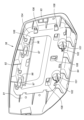
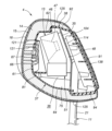
- a perspective view of a seat according to an embodiment Perspective view of headrest Disassembled perspective view of headrest A perspective view showing a headrest main body and a headrest pillar Perspective view of the support plate seen from the rear Front perspective view of support plate Perspective view of the front case seen from the rear Perspective view of the rear case seen from the front Perspective view of the rear case viewed from the rear Longitudinal cross-sectional view of the headrest (X-X cross-sectional view in Fig. 2) Longitudinal cross-sectional view of the headrest (XI-XI cross-sectional view in Fig. 2) Horizontal sectional view of the headrest (XII-XII sectional view in Fig. 2)
- Headrests are applied to vehicle seats. In the following embodiments, an example of a headrest of an automobile seat will be described.
- the seat 1 has a seat cushion 2, a seat back 3, and a headrest 4.
- the seat cushion 2 supports the user's buttocks from below.
- the seatback 3 extends upward from the rear portion of the seat cushion 2 .
- the seat back 3 supports the user's back from behind.
- a headrest 4 is provided at the upper end of the seat back 3 .
- the headrest 4 supports the user's head from behind.
- the headrest 4 has a headrest pillar 11, a headrest body 12, at least one speaker 13, a pad 14, at least one shape retainer 15, and a skin material 16. .
- the headrest pillar 11 is supported by the seat back 3.
- the headrest pillar 11 has left and right vertical portions 21 extending in the vertical direction, and horizontal portions 22 extending in the horizontal direction and connected to upper ends of the left and right vertical portions 21 .
- Passage holes 25 in which wire harnesses 24 are arranged are formed inside the left and right vertical portions 21 and the horizontal portions 22 .
- the passage hole 25 has lower openings 26 at the lower ends of the left and right vertical portions 21 .
- the passage hole 25 also has an upper opening 27 in the lateral portion 22 .
- Grommets 28 are attached to the lower opening 26 and the upper opening 27 .
- the grommet 28 is preferably made of a resin material.
- the headrest pillar 11 is preferably formed by bending a metal pipe.
- the left and right vertical portions 21 are supported by a seatback frame 29 forming the skeleton of the seatback 3 .
- the seat back frame 29 is provided with left and right pillar support portions 30 for receiving the vertical portion 21 .
- the pillar support portion 30 is formed in a tubular shape with both ends opened.
- the pillar support portion 30 is preferably made of a resin material.
- the vertical portions 21 are inserted into corresponding pillar supports 30 .
- a lower end of the vertical portion 21 protrudes from a lower end of the pillar support portion 30 .
- the outer surface of the vertical portion 21 is formed with a plurality of locking grooves 31 arranged at intervals in the longitudinal direction. As shown in FIG.
- the pillar support portion 30 is provided with a locking device 32 that selectively locks one of the plurality of locking grooves 31 .
- the height of the headrest 4 with respect to the seat back 3 is determined by locking one of the locking grooves 31 with the locking device 32 .
- the headrest body 12 is coupled to the headrest pillar 11.
- the headrest body 12 includes a support plate 35 coupled to the headrest pillar 11 and facing forward and backward, a front case 37 provided on the front side of the support plate 35 and forming an internal space 36 between the support plate 35 and the support plate 35 . and a rear case 38 provided on the rear side of the.
- the support plate 35 is preferably made of a metal plate.
- the front case 37 and the rear case 38 are preferably made of a resin material.
- the support plate 35 faces forward and backward and extends left and right. Headrest pillar 11 is coupled to the rear surface of support plate 35 . More specifically, the horizontal portion 22 and the left and right vertical portions 21 are preferably welded to the rear surface of the support plate 35 .
- At least one central opening 41 penetrating in the thickness direction is formed in the central portion of the support plate 35 .
- Left and right engagement grooves 42 recessed downward are formed in the upper edge of the support plate 35 .
- At least one first fastening hole 43 is formed through the lower portion of the support plate 35 in the thickness direction.
- a pair of left and right speakers 13 are supported by the headrest body 12 .
- a pair of left and right speakers 13 are provided at the left and right ends of the front surface of the support plate 35 .
- Each speaker 13 has a vertically elongated rectangular parallelepiped speaker case 46 .
- a speaker unit 47 for outputting sound is provided inside the speaker case 46 .
- the speaker unit 47 is exposed on the front surface of the speaker case 46 and outputs sound toward the front of the speaker case 46 .
- Each speaker 13 preferably has a sound absorbing material 48 attached to the front surface of the support plate 35 .
- the sound absorbing material 48 may be a vibration isolating material such as a rubber sheet or felt. The sound absorbing material 48 suppresses transmission of vibration of the speaker 13 to the support plate 35 .
- a microphone unit 51 is coupled to the lower end of each speaker 13 .
- the microphone unit 51 may be omitted.
- the control device 53 is an electronic control device and an arithmetic device having a microprocessor (MPU), a nonvolatile memory, a volatile memory, and an interface.
- MPU microprocessor
- the control device 53 realizes various applications by the microprocessor executing programs stored in the nonvolatile memory.
- the control device 53 may be arranged inside the seat back 3 or below the seat cushion 2 or the like.
- the wire harness 24 passes through the lower opening 26 , the passage hole 25 and the upper opening 27 from inside the seat back 3 and reaches the inside of the headrest 4 .
- the wire harness 24 is supported by a harness locking portion 59 coupled to the back surface of the support plate 35 .
- the harness locking portion 59 is a resin clip having a ring portion through which the wire harness 24 passes.
- the harness locking portion 59 is locked in a locking hole formed in the support plate 35 by a locking claw.
- An upper end portion of the wire harness 24 branches into a plurality of branch portions 54 . Each branch 54 passes through the central opening 41 and extends to the front side of the support plate 35 .
- Each branch portion 54 is provided with a connector 55 .
- each speaker 13 has a harness 13B with a connector 13A at its tip.
- each microphone unit 51 has a harness 51B having a connector 51A at its tip.
- Each connector 13A, 51A is provided with locking claws 13C, 51C. The locking claws 13C and 51C are engaged with locking holes formed in the support plate 35.
- each connector 13A, 51A is attached to the front surface of the support plate 35.
- Each connector 13 A, 51 A may be arranged around a plurality of central openings 41 .
- a pair of connectors 13A are arranged on the left and right of the central opening 41 on the upper side, and a pair of connectors 51A are arranged on the left and right of the central opening 41 on the lower side.
- Each connector 55 is connected to the corresponding connector 13A, 51A.
- the front case 37 is formed in a box shape that opens toward the rear.
- the front case 37 includes a front wall portion 61 facing front and back, an upper wall portion 62 extending rearward from the upper edge of the front wall portion 61, and left and right side wall portions extending rearward from the left and right side edges of the front wall portion 61. 63 and a lower wall portion 64 extending rearward from the lower edge of the front wall portion 61 . Left and right side portions of the front wall portion 61 are inclined forward toward the sides.
- the front case 37 has at least one case opening 66 penetrating back and forth in a portion facing the speaker 13 .
- case openings 66 are formed on the left and right side portions of the front wall portion 61 .
- Grids 67 are provided in the left and right case openings 66 .
- a partition wall 69 that protrudes rearward and extends vertically is provided in the central portion of the rear surface of the front wall portion 61 .
- the partition wall 69 is preferably connected to the upper wall portion 62 and the lower wall portion 64 .
- the partition wall 69 may be formed integrally with the front case 37 .
- the partition wall 69 is a member independent of the front case 37 and may be formed of a different member.
- the partition wall 69 may be made of a sound absorbing material such as urethane foam and attached to the front case 37 .
- a pair of left and right upper bosses 71 projecting rearward are provided on the upper portion of the back surface of the front wall portion 61 .
- the left and right upper bosses 71 are arranged on the left and right sides of the partition wall 69 .
- Rear ends of the left and right upper bosses 71 are provided with connecting pieces 72 extending rearward.
- the coupling piece 72 has a claw portion extending downward.
- Lightening portions 73 are formed inside the left and right upper bosses 71, respectively. Each lightening portion 73 opens to the front surface of the front wall portion 61 .
- a pair of left and right lower bosses 75 projecting rearward are provided on the lower part of the back surface of the front wall part 61 .
- the left and right lower bosses 75 are arranged on the left and right sides of the partition wall 69 .
- the left and right lower bosses 75 are cylindrical and have bottom plate portions 76 at their rear ends.
- a second fastening hole 77 is formed through the bottom plate portion 76 in the thickness direction.
- funnels 81 extending toward the speaker 13 are provided at the edges of the case opening 66, respectively.
- the funnel 81 is cylindrical and extends rearward from the back surface of the front wall portion 61 .
- the rear end of the funnel 81 faces the speaker unit 47 which is the output section of the speaker 13 .
- a plurality of first cover locking holes 83 are formed in each of the left and right side wall portions 63 of the front case 37 .
- the plurality of first cover locking holes 83 pass through the corresponding side wall portions 63 in the thickness direction.
- the rear case 38 is shaped like a box that opens forward.
- the rear case 38 includes a rear wall portion 91 facing forward and backward, an upper wall portion 92 extending forward from the upper edge of the rear wall portion 91, and left and right side wall portions extending rearward from the left and right side edges of the rear wall portion 91. and a lower wall portion 94 extending rearward from the lower edge of the rear wall portion 91 .
- a pair of left and right rear hooks 96 projecting forward and extending downward are provided on the upper portion of the front surface of the rear wall portion 91 .
- a coupling hole 97 recessed rearward is formed at the front end of the rear hook 96 .
- the coupling hole 97 receives the coupling piece 72 .
- a pair of left and right rear bosses 101 projecting forward are provided at the lower portion of the front surface of the rear wall portion 91 .
- a female threaded hole 102 is formed in each rear boss 101 .
- Female screw hole 102 extends rearward from the front end surface of rear boss 101 .
- At least one convex portion 104 projecting forward is formed on the front surface of the rear wall portion 91 .
- At least one protrusion 104 may be connected to each other or may be independent of each other.
- the convex portion 104 is annularly formed in the central portion of the front surface of the rear lower portion.
- the projections 104 are connected to the left and right rear hooks 96 and the left and right rear bosses 101 .
- a recess 105 recessed forward is formed in a portion corresponding to the protrusion 104 on the rear surface of the rear wall portion 91 .
- a plurality of skin hooks 106 are provided on the sidewall of the recess 105 forming the edge of the recess 105 .
- a plurality of second cover locking holes 108 penetrating in the thickness direction are formed in the bottom of the recess 105 forming the bottom of the recess 105 .
- the left and right rear hooks 96 are hooked on the left and right engagement grooves 42 of the support plate 35 .
- the rear case 38 is thereby supported by the support plate 35 .
- the convex portion 104 contacts the rear surface of the support plate 35 and the left and right vertical portions 21 of the headrest pillar 11 .
- the front ends of the left and right rear bosses 101 abut on the edges of the corresponding first fastening holes 43 on the rear surface of the support plate 35 .
- each female screw hole 102 faces the corresponding first fastening hole 43 .
- the rear case 38 is thus supported by the support plate 35 . Front ends of the left and right rear hooks 96 protrude forward from the support plate 35 .
- each bottom plate portion 76 of each lower boss 75 of the front case 37 contacts the edge of the first fastening hole 43 on the front surface of the support plate 35 .
- the left and right second fastening holes 77 face the corresponding first fastening holes 43 .
- the front case 37, the support plate 35, and the rear case 38 are fastened together by a screw 103 that passes through the second fastening hole 77 and the first fastening hole 43 from the front side of the front case 37 and is screwed into the female screw hole 102. there is By connecting the front case 37 and the rear case 38 to each other in this manner, the support plate 35 is sandwiched between the front case 37 and the rear case 38 .
- first cushioning materials 111 may be provided between the left and right rear hooks 96 and the left and right engagement grooves 42 .
- a second cushioning material 112 may be provided between the bottom plate portion 76 of the lower boss 75 and the support plate 35 .
- a third cushioning material 113 may be provided between the front end of the rear boss 101 and the support plate 35 .
- a fourth cushioning material 114 may be provided between the convex portion 104 and the rear surface of the support plate 35 and between the convex portion 104 and the headrest pillar 11 .
- the first to fourth cushioning materials 114 are preferably made of a flexible material such as rubber or felt. The first to fourth cushioning materials 111 to 114 suppress the transmission of vibrations among the support plate 35, the front case 37 and the rear case .
- an internal space 36 is formed between the support plate 35 and the front case 37 when the front case 37 and the rear case 38 are coupled to the support plate 35 .
- a partition wall 69 of the front case 37 partitions the internal space 36 into left and right portions.
- the left and right speakers 13 are arranged in the internal space 36 .
- the partition wall 69 is made of a flexible sound absorbing material, the rear end of the partition wall 69 is preferably in contact with the front surface of the support plate 35 .
- the partition 69 is formed integrally with the front case 37 , the rear end of the partition 69 is preferably separated from the front surface of the support plate 35 .
- a flexible sound absorbing material may be filled between the rear end of the partition wall 69 and the support plate 35 .
- a sound absorbing material 117 is provided around each speaker 13 .
- the sound absorbing material 117 may be annularly provided so as to surround the upper surface, the lower surface, and the left and right side surfaces of the speaker 13 .
- Sound absorbing material 117 may be, for example, urethane foam.
- a sound absorbing material 118 is provided between the partition wall 69 and the left and right speakers 13 .
- the sound absorbing material 118 is preferably provided along the left and right side surfaces of the partition wall 69 .
- Each sound absorbing material 118 is preferably filled in a space between the partition wall 69 and the sound absorbing material 117 attached to the speaker 13 .
- the sound absorbing material 118 may be made of felt, for example.
- the pad 14 covers the headrest body 12. As shown in FIGS. That is, the pads 14 are provided along the outer surfaces of the front case 37 and the rear case 38 .
- the pad 14 includes at least the front surface of the front wall portion 61 of the front case 37, the upper wall portion 62 of the front case 37 and the upper wall portion 92 of the rear case 38, the lower wall portion 64 of the front case 37 and the lower wall of the rear case 38. 94 , along the left and right side wall portions 63 of the front case 37 and the left and right side wall portions 93 of the rear case 38 .
- Pad 14 is formed from a material having mobility.
- the pad 14 may be made of foamed urethane, for example.
- the pad 14 has at least one pad opening 121 in a portion facing the speaker 13 .
- a plurality of pad openings 121 are arranged in front of the left and right case openings 66 of the front case 37 .
- Each pad opening 121 opens in front of the pad 14 .
- Each pad opening 121 penetrates the pad 14 in the thickness direction.
- One pad opening 121 may be formed for one case opening 66 , or a plurality of pad openings 121 may be formed for one case opening 66 .
- a plurality of pad openings 121 communicate with corresponding case openings 66 .
- a pair of left and right shape retainers 15 are provided on the outer surface of the pad 14. As shown in FIGS. Each shape retainer 15 is provided along the outer surface of the pad 14 so as to cover the pad opening 121 . The shape retainer 15 is bonded to the outer surface of the pad 14 at the edges. The shape retainer 15 is preferably formed in a mesh shape. Shape retainer 15 has higher rigidity than pad 14 . The shape retainer 15 preferably has a Young's modulus higher than that of the pad 14 .
- a frame portion 125 having higher rigidity than the shape retainer 15 is provided at the edge of the shape retainer 15 .
- the frame portion 125 is preferably made of a sheet material such as woven fabric.
- the frame portion 125 preferably has a Young's modulus higher than that of the shape retainer 15 .
- the shape retainer 15 is preferably coupled to the outer surface of the pad 14 via the frame portion 125 . That is, it is preferable that the frame portion 125 is coupled to the pad 14 .
- the frame portion 125 may be coupled to the pad 14 by, for example, an adhesive or double-sided tape.
- Each shape retainer 15 preferably extends vertically along the front surface of the pad 14 and is coupled to the upper and lower ends of the pad 14 .
- the upper end of shape retainer 15 may extend rearward beyond the upper rear end of pad 14 and be coupled to rear case 38 .
- the lower end of the shape retainer 15 may extend rearward beyond the lower rear end of the pad 14 and be coupled to the rear case 38 .
- the skin material 16 covers the pad 14 and the shape retaining material 15 .
- the upholstery material 16 is preferably formed in the shape of a bag that is open to the rear. Edges of the skin material 16 are engaged with a plurality of skin hooks 106 formed on the rear surface of the rear case 38 .
- a plurality of through-holes 126 penetrating in the thickness direction are preferably formed in portions of the skin material 16 facing the plurality of pad openings 121 .
- a rear cover 130 is attached to the rear surface of the rear case 38, as shown in FIGS.
- the rear cover 130 has a cover center portion 131 extending left and right, and left and right cover side portions 132 extending forward from both left and right ends of the cover center portion 131 .
- the cover central portion 131 is formed in a plate shape facing forward and backward.
- the left and right cover side portions 132 are formed in plate shapes facing left and right.
- the left and right cover side portions 132 are provided with first locking claws 134 that are locked to the left and right first cover locking holes 83 of the front case 37, respectively. Through holes through which the left and right first locking claws 134 pass are formed in the pad 14 and the skin material 16 .
- a plurality of second locking claws 135 formed in the plurality of second cover locking holes 108 of the rear case 38 are provided in the cover central portion 131 .
- a cover central portion 131 of the rear cover 130 covers the concave portion 105 of the rear case 38 and hides the edge of the skin material 16 .
- the left and right cover side portions 132 constitute left and right end portions of the headrest 4 .
- a damping material 138 is provided on the front surface of the rear cover 130 .
- a plurality of damping materials 138 may be attached to the front surface of the central portion 131 of the cover.
- the damping material 138 may be, for example, a rubber sheet.
- the damping material 138 is preferably sandwiched between the rear cover 130 and the rear case 38 .
- the damping material 138 suppresses vibration of the rear case 38 and suppresses transmission of sound rearward from the headrest 4 .
- the headrest pillar 11 is joined to the support plate 35 by welding or the like.
- the speaker 13 and the microphone unit 51 are fastened to the support plate 35 via the sound absorbing material 48 .
- a connector 13A of the speaker 13 is coupled to the support plate 35 by a locking claw 13C.
- a connector 51A of the microphone unit 51 is coupled to the support plate 35 by a locking claw 51C.
- the wire harness 24 is inserted into the passage hole 25 of the headrest pillar 11 and the pillar support portion 30 .
- at least one connector at both ends of the wire harness 24 is removed.
- the end of the wire harness 24 on the control device 53 side may be inserted into the passage hole 25 from the upper opening 27 .
- the end of the wire harness 24 on the control device 53 side is pulled out from the lower opening 26 and passes through the pillar support portion 30 , the end of the wire harness 24 on the control device 53 side is connected to the control device 53 .
- a connector may be attached for Also, each connector 55 is connected to the corresponding connector 13A, 51A.
- the rear case 38 is locked to the support plate 35.
- the front case 37 is coupled to the rear case 38.
- the front case 37 and the rear case 38 sandwich the support plate 35 .
- the headrest body 12 is formed by the support plate 35 , the front case 37 and the rear case 38 .
- the front case 37 and the rear case 38 are covered with the pad 14 .
- the shape retainer 15 having the frame portion 125 is bonded to the surface of the pad 14 .
- the pad 14 , the shape retaining material 15 and the frame portion 125 are covered with the skin material 16 . Edges of the skin material 16 are engaged with a plurality of skin hooks 106 of the rear case 38 .
- the headrest 4 is formed by the above assembly procedure.
- the shape retainer 15 is provided on the outer surface side of the opening of the pad 14, local deformation can be suppressed. Since the shape retainer 15 imparts rigidity to the pad 14, deformation of the opening of the pad 14 is suppressed. By providing the frame portion 125 at the edge portion of the shape retainer 15, the rigidity of the shape retainer 15 is increased, and the deformation of the pad opening 121 is further suppressed. By arranging the shape retainer 15 over a relatively wide range, the load applied to the pad 14 is dispersed, and local deformation of the pad 14 is further suppressed.
- the sound absorbing material 117 suppresses vibrations transmitted from the speaker 13 to the support plate 35, the front case 37, and the rear case 38.
- the sound absorbing material 118 and the partition wall 69 suppress interference of sounds output from the left and right speakers 13 .
- the funnel 81 regulates the direction of sound output from each speaker 13 and transmits the sound forward to the headrest 4 . This suppresses interference between sounds output from the left and right speakers 13 .
- the shape retainer 15 may be provided over the entire surface of the pad 14 . Also, the shape retaining material 15 may be bonded to the back surface of the skin material 16 .
Landscapes
- Engineering & Computer Science (AREA)
- Aviation & Aerospace Engineering (AREA)
- Transportation (AREA)
- Mechanical Engineering (AREA)
- Fittings On The Vehicle Exterior For Carrying Loads, And Devices For Holding Or Mounting Articles (AREA)
- Chair Legs, Seat Parts, And Backrests (AREA)
- Seats For Vehicles (AREA)
Priority Applications (3)
| Application Number | Priority Date | Filing Date | Title |
|---|---|---|---|
| US18/685,299 US20250121757A1 (en) | 2021-09-28 | 2022-09-26 | Headrest |
| JP2023551467A JP7656231B2 (ja) | 2021-09-28 | 2022-09-26 | ヘッドレスト |
| JP2025035681A JP2025074360A (ja) | 2021-09-28 | 2025-03-06 | ヘッドレスト |
Applications Claiming Priority (2)
| Application Number | Priority Date | Filing Date | Title |
|---|---|---|---|
| US202163261755P | 2021-09-28 | 2021-09-28 | |
| US63/261,755 | 2021-09-28 |
Publications (1)
| Publication Number | Publication Date |
|---|---|
| WO2023054248A1 true WO2023054248A1 (ja) | 2023-04-06 |
Family
ID=85782645
Family Applications (1)
| Application Number | Title | Priority Date | Filing Date |
|---|---|---|---|
| PCT/JP2022/035665 Ceased WO2023054248A1 (ja) | 2021-09-28 | 2022-09-26 | ヘッドレスト |
Country Status (3)
| Country | Link |
|---|---|
| US (1) | US20250121757A1 (https=) |
| JP (2) | JP7656231B2 (https=) |
| WO (1) | WO2023054248A1 (https=) |
Citations (3)
| Publication number | Priority date | Publication date | Assignee | Title |
|---|---|---|---|---|
| JPH0369466U (https=) * | 1989-11-11 | 1991-07-10 | ||
| JP2009247388A (ja) * | 2008-04-01 | 2009-10-29 | Toyota Boshoku Corp | ヘッドレスト |
| JP2009291454A (ja) * | 2008-06-06 | 2009-12-17 | Inoac Corp | スピーカ付きヘッドレスト |
Family Cites Families (3)
| Publication number | Priority date | Publication date | Assignee | Title |
|---|---|---|---|---|
| JPS62119859U (https=) * | 1986-01-22 | 1987-07-30 | ||
| JPH0994129A (ja) * | 1995-09-28 | 1997-04-08 | Suzuki Motor Corp | 自動車シートのヘッドレスト取付装置 |
| US10271119B2 (en) * | 2015-02-14 | 2019-04-23 | Delta Tooling Co., Ltd. | Headrest having speaker |
-
2022
- 2022-09-26 JP JP2023551467A patent/JP7656231B2/ja active Active
- 2022-09-26 US US18/685,299 patent/US20250121757A1/en active Pending
- 2022-09-26 WO PCT/JP2022/035665 patent/WO2023054248A1/ja not_active Ceased
-
2025
- 2025-03-06 JP JP2025035681A patent/JP2025074360A/ja active Pending
Patent Citations (3)
| Publication number | Priority date | Publication date | Assignee | Title |
|---|---|---|---|---|
| JPH0369466U (https=) * | 1989-11-11 | 1991-07-10 | ||
| JP2009247388A (ja) * | 2008-04-01 | 2009-10-29 | Toyota Boshoku Corp | ヘッドレスト |
| JP2009291454A (ja) * | 2008-06-06 | 2009-12-17 | Inoac Corp | スピーカ付きヘッドレスト |
Also Published As
| Publication number | Publication date |
|---|---|
| JPWO2023054248A1 (https=) | 2023-04-06 |
| JP7656231B2 (ja) | 2025-04-03 |
| JP2025074360A (ja) | 2025-05-13 |
| US20250121757A1 (en) | 2025-04-17 |
Similar Documents
| Publication | Publication Date | Title |
|---|---|---|
| JP6650477B2 (ja) | 乗物用シート | |
| EP3257402B1 (en) | Headrest having speaker | |
| EP3003777B1 (en) | Vehicle seat | |
| JP7307353B2 (ja) | 乗物用シート | |
| JP2008295597A (ja) | ヘッドレスト及びその製造方法 | |
| US7413248B2 (en) | Acoustic structure of seat back | |
| JP6495358B2 (ja) | 乗物用シート | |
| JP2014201244A (ja) | 車両用シート | |
| JP2026031675A (ja) | 乗り物用シート | |
| WO2023054248A1 (ja) | ヘッドレスト | |
| JP2022162037A (ja) | 乗物用シート | |
| WO2018154828A1 (ja) | シート | |
| JP6920622B2 (ja) | 乗物用シート | |
| JP2021181302A (ja) | 乗物用シート | |
| WO2023228961A1 (ja) | 乗り物用シート | |
| JP2005199936A (ja) | クッションパッド | |
| JP2017124690A (ja) | ヘッドレスト装置、及びヘッドレスト装置の製造方法 | |
| JP2022104030A (ja) | シート | |
| JP6224430B2 (ja) | ヘッドレスト、車両用シート及びヘッドレスト一体型車両用シート | |
| JP2018135073A (ja) | 乗物用シート | |
| JP2012056481A (ja) | シートバックボード及びこれを用いた車両用シート | |
| JP4627734B2 (ja) | 骨振動式音響シート | |
| JP6898571B2 (ja) | 乗物用シート | |
| JP6440301B2 (ja) | 椅子用遮蔽部材、及び、椅子 | |
| JP2024072781A (ja) | ヘッドレスト |
Legal Events
| Date | Code | Title | Description |
|---|---|---|---|
| 121 | Ep: the epo has been informed by wipo that ep was designated in this application |
Ref document number: 22876115 Country of ref document: EP Kind code of ref document: A1 |
|
| WWE | Wipo information: entry into national phase |
Ref document number: 2023551467 Country of ref document: JP |
|
| WWE | Wipo information: entry into national phase |
Ref document number: 18685299 Country of ref document: US |
|
| NENP | Non-entry into the national phase |
Ref country code: DE |
|
| 122 | Ep: pct application non-entry in european phase |
Ref document number: 22876115 Country of ref document: EP Kind code of ref document: A1 |
|
| WWP | Wipo information: published in national office |
Ref document number: 18685299 Country of ref document: US |