WO2023054248A1 - Headrest - Google Patents
Headrest Download PDFInfo
- Publication number
- WO2023054248A1 WO2023054248A1 PCT/JP2022/035665 JP2022035665W WO2023054248A1 WO 2023054248 A1 WO2023054248 A1 WO 2023054248A1 JP 2022035665 W JP2022035665 W JP 2022035665W WO 2023054248 A1 WO2023054248 A1 WO 2023054248A1
- Authority
- WO
- WIPO (PCT)
- Prior art keywords
- headrest
- pad
- support plate
- case
- speaker
- Prior art date
Links
- 239000000463 material Substances 0.000 claims abstract description 58
- 239000011358 absorbing material Substances 0.000 claims description 31
- 238000005192 partition Methods 0.000 claims description 29
- 238000013016 damping Methods 0.000 claims description 9
- 230000000149 penetrating effect Effects 0.000 claims description 7
- 230000008878 coupling Effects 0.000 claims description 5
- 238000010168 coupling process Methods 0.000 claims description 5
- 238000005859 coupling reaction Methods 0.000 claims description 5
- 210000000078 claw Anatomy 0.000 description 9
- 230000005540 biological transmission Effects 0.000 description 5
- 239000011347 resin Substances 0.000 description 4
- 229920005989 resin Polymers 0.000 description 4
- 238000009423 ventilation Methods 0.000 description 4
- JOYRKODLDBILNP-UHFFFAOYSA-N Ethyl urethane Chemical compound CCOC(N)=O JOYRKODLDBILNP-UHFFFAOYSA-N 0.000 description 3
- 239000006260 foam Substances 0.000 description 2
- 239000002184 metal Substances 0.000 description 2
- 238000000034 method Methods 0.000 description 2
- 230000001105 regulatory effect Effects 0.000 description 2
- 239000000853 adhesive Substances 0.000 description 1
- 230000001070 adhesive effect Effects 0.000 description 1
- 238000005452 bending Methods 0.000 description 1
- 210000001217 buttock Anatomy 0.000 description 1
- 238000004519 manufacturing process Methods 0.000 description 1
- 238000003466 welding Methods 0.000 description 1
- 239000002759 woven fabric Substances 0.000 description 1
Images


Classifications
-
- B—PERFORMING OPERATIONS; TRANSPORTING
- B60—VEHICLES IN GENERAL
- B60N—SEATS SPECIALLY ADAPTED FOR VEHICLES; VEHICLE PASSENGER ACCOMMODATION NOT OTHERWISE PROVIDED FOR
- B60N2/00—Seats specially adapted for vehicles; Arrangement or mounting of seats in vehicles
- B60N2/80—Head-rests
- B60N2/879—Head-rests with additional features not related to head-rest positioning, e.g. heating or cooling devices or loudspeakers
Definitions
- the present invention relates to a headrest of a vehicle seat.
- Patent Document 1 discloses a headrest having a speaker inside.
- the headrest has a frame forming a cavity, a pad provided on the outer surface of the frame, and a skin material covering the pad.
- a speaker is arranged facing the cavity, and an opening is formed in the frame. Ventilation holes communicating with the opening are formed in the pad and the skin material. Sound output from the speaker is transmitted to the outside of the headrest through the cavity, the opening, and the ventilation hole.
- an object of the present invention is to suppress local deformation of a pad in a headrest with built-in speakers.
- one aspect of the present invention is a headrest (4) of a vehicle seat (1), comprising a headrest pillar (11) supported by a seat back (3), and A combined headrest body (12), at least one speaker (13) supported by the headrest body, and at least one pad opening (121) covering the headrest body and facing the speaker.
- a mesh shape retainer (15) provided along the outer surface of the pad so as to cover the pad opening and bonded to the outer surface of the pad at the edge; It has a pad and a skin material (16) covering the shape retaining material.
- the edge of the shape retainer may be provided with a frame (125) having higher rigidity than the shape retainer, and the frame may be coupled to the pad.
- deformation of the pad opening is further suppressed by the shape retainer and the frame.
- the pad opening may open on the front surface of the pad
- the shape retainer may extend vertically on the front surface of the pad and be coupled to the upper and lower ends of the pad.
- the shape retainer is arranged in a relatively wide range, the load applied to the pad is dispersed, and local deformation of the pad is further suppressed.
- the headrest body includes a support plate (35) coupled to the headrest pillar and facing forward and backward, and an internal space (36) provided in front of the support plate to form an internal space (36) between the support plate and the support plate. and a rear case (38) provided on the rear side of the support plate, wherein the speaker is supported on the front surface of the support plate, is arranged in the internal space, and is arranged in the front case. has at least one case opening (66) penetrating back and forth in a portion facing the speaker, and a first sound absorbing material (117) may be provided around the speaker.
- the vibration transmitted from the speaker to the support plate, the front case, and the rear case is suppressed by the first sound absorbing material.
- the speakers are provided at the left and right ends of the front surface of the support plate, respectively, and a partition wall (69) is provided at the central portion of the internal space in the horizontal direction to divide the internal space into left and right.
- the edge of the case opening may be provided with a funnel (81) extending toward the speaker.
- the direction of sound output from each speaker is regulated by the funnel. This suppresses interference between sounds output from the left and right speakers.
- a second sound absorbing material may be provided between the partition wall and the left and right speakers.
- the partition wall may be made of a flexible sound absorbing material.
- the front case and the rear case are coupled to each other so that the support plate is sandwiched between the front case and the rear case, and the front case and the rear case and the support plate are separated from each other. , may be in contact with each other via cushioning materials (111 to 114).
- vibration transmitted from the support plate to the front case and the rear case can be suppressed.
- a rear cover (130) may be coupled to the rear surface of the rear case, and a damping material (138) may be provided on the front surface of the rear cover.
- One aspect of the present invention is a headrest (4) for a vehicle seat (1), comprising a headrest pillar (11) supported by a seat back (3) and a headrest body (12) coupled to the headrest pillar. at least one speaker (13) supported by the headrest body; a pad (14) covering the headrest body and having at least one pad opening (121) in a portion facing the speaker; A mesh-like shape retainer (15) provided along the outer surface of the pad so as to cover the pad opening and bonded to the outer surface of the pad at the edge, and covering the pad and the shape retainer. and a skin material (16).
- the edge of the shape retainer may be provided with a frame (125) having higher rigidity than the shape retainer, and the frame may be coupled to the pad.
- deformation of the pad opening is further suppressed by the shape retainer and the frame.
- the pad opening may open on the front surface of the pad
- the shape retainer may extend vertically on the front surface of the pad and be coupled to the upper and lower ends of the pad.
- the shape retainer is arranged in a relatively wide range, the load applied to the pad is dispersed, and local deformation of the pad is further suppressed.
- the headrest body includes a support plate (35) coupled to the headrest pillar and facing forward and backward, and an internal space (36) provided in front of the support plate to form an internal space (36) between the support plate and the support plate. and a rear case (38) provided on the rear side of the support plate, wherein the speaker is supported on the front surface of the support plate, is arranged in the internal space, and is arranged in the front case. has at least one case opening (66) penetrating back and forth in a portion facing the speaker, and a first sound absorbing material (117) may be provided around the speaker.
- the vibration transmitted from the speaker to the support plate, the front case, and the rear case is suppressed by the first sound absorbing material.
- the speakers are provided at the left and right ends of the front surface of the support plate, respectively, and a partition wall (69) is provided at the central portion of the internal space in the horizontal direction to divide the internal space into left and right.
- the edge of the case opening may be provided with a funnel (81) extending toward the speaker.
- the direction of sound output from each speaker is regulated by the funnel. This suppresses interference between sounds output from the left and right speakers.
- a second sound absorbing material may be provided between the partition wall and the left and right speakers.
- the partition wall may be made of a flexible sound absorbing material.
- the front case and the rear case are coupled to each other so that the support plate is sandwiched between the front case and the rear case, and the front case and the rear case and the support plate are separated from each other. , may be in contact with each other via cushioning materials (111 to 114).
- vibration transmitted from the support plate to the front case and the rear case can be suppressed.
- a rear cover (130) may be coupled to the rear surface of the rear case, and a damping material (138) may be provided on the front surface of the rear cover.
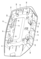
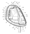
- a perspective view of a seat according to an embodiment Perspective view of headrest Disassembled perspective view of headrest A perspective view showing a headrest main body and a headrest pillar Perspective view of the support plate seen from the rear Front perspective view of support plate Perspective view of the front case seen from the rear Perspective view of the rear case seen from the front Perspective view of the rear case viewed from the rear Longitudinal cross-sectional view of the headrest (X-X cross-sectional view in Fig. 2) Longitudinal cross-sectional view of the headrest (XI-XI cross-sectional view in Fig. 2) Horizontal sectional view of the headrest (XII-XII sectional view in Fig. 2)
- Headrests are applied to vehicle seats. In the following embodiments, an example of a headrest of an automobile seat will be described.
- the seat 1 has a seat cushion 2, a seat back 3, and a headrest 4.
- the seat cushion 2 supports the user's buttocks from below.
- the seatback 3 extends upward from the rear portion of the seat cushion 2 .
- the seat back 3 supports the user's back from behind.
- a headrest 4 is provided at the upper end of the seat back 3 .
- the headrest 4 supports the user's head from behind.
- the headrest 4 has a headrest pillar 11, a headrest body 12, at least one speaker 13, a pad 14, at least one shape retainer 15, and a skin material 16. .
- the headrest pillar 11 is supported by the seat back 3.
- the headrest pillar 11 has left and right vertical portions 21 extending in the vertical direction, and horizontal portions 22 extending in the horizontal direction and connected to upper ends of the left and right vertical portions 21 .
- Passage holes 25 in which wire harnesses 24 are arranged are formed inside the left and right vertical portions 21 and the horizontal portions 22 .
- the passage hole 25 has lower openings 26 at the lower ends of the left and right vertical portions 21 .
- the passage hole 25 also has an upper opening 27 in the lateral portion 22 .
- Grommets 28 are attached to the lower opening 26 and the upper opening 27 .
- the grommet 28 is preferably made of a resin material.
- the headrest pillar 11 is preferably formed by bending a metal pipe.
- the left and right vertical portions 21 are supported by a seatback frame 29 forming the skeleton of the seatback 3 .
- the seat back frame 29 is provided with left and right pillar support portions 30 for receiving the vertical portion 21 .
- the pillar support portion 30 is formed in a tubular shape with both ends opened.
- the pillar support portion 30 is preferably made of a resin material.
- the vertical portions 21 are inserted into corresponding pillar supports 30 .
- a lower end of the vertical portion 21 protrudes from a lower end of the pillar support portion 30 .
- the outer surface of the vertical portion 21 is formed with a plurality of locking grooves 31 arranged at intervals in the longitudinal direction. As shown in FIG.
- the pillar support portion 30 is provided with a locking device 32 that selectively locks one of the plurality of locking grooves 31 .
- the height of the headrest 4 with respect to the seat back 3 is determined by locking one of the locking grooves 31 with the locking device 32 .
- the headrest body 12 is coupled to the headrest pillar 11.
- the headrest body 12 includes a support plate 35 coupled to the headrest pillar 11 and facing forward and backward, a front case 37 provided on the front side of the support plate 35 and forming an internal space 36 between the support plate 35 and the support plate 35 . and a rear case 38 provided on the rear side of the.
- the support plate 35 is preferably made of a metal plate.
- the front case 37 and the rear case 38 are preferably made of a resin material.
- the support plate 35 faces forward and backward and extends left and right. Headrest pillar 11 is coupled to the rear surface of support plate 35 . More specifically, the horizontal portion 22 and the left and right vertical portions 21 are preferably welded to the rear surface of the support plate 35 .
- At least one central opening 41 penetrating in the thickness direction is formed in the central portion of the support plate 35 .
- Left and right engagement grooves 42 recessed downward are formed in the upper edge of the support plate 35 .
- At least one first fastening hole 43 is formed through the lower portion of the support plate 35 in the thickness direction.
- a pair of left and right speakers 13 are supported by the headrest body 12 .
- a pair of left and right speakers 13 are provided at the left and right ends of the front surface of the support plate 35 .
- Each speaker 13 has a vertically elongated rectangular parallelepiped speaker case 46 .
- a speaker unit 47 for outputting sound is provided inside the speaker case 46 .
- the speaker unit 47 is exposed on the front surface of the speaker case 46 and outputs sound toward the front of the speaker case 46 .
- Each speaker 13 preferably has a sound absorbing material 48 attached to the front surface of the support plate 35 .
- the sound absorbing material 48 may be a vibration isolating material such as a rubber sheet or felt. The sound absorbing material 48 suppresses transmission of vibration of the speaker 13 to the support plate 35 .
- a microphone unit 51 is coupled to the lower end of each speaker 13 .
- the microphone unit 51 may be omitted.
- the control device 53 is an electronic control device and an arithmetic device having a microprocessor (MPU), a nonvolatile memory, a volatile memory, and an interface.
- MPU microprocessor
- the control device 53 realizes various applications by the microprocessor executing programs stored in the nonvolatile memory.
- the control device 53 may be arranged inside the seat back 3 or below the seat cushion 2 or the like.
- the wire harness 24 passes through the lower opening 26 , the passage hole 25 and the upper opening 27 from inside the seat back 3 and reaches the inside of the headrest 4 .
- the wire harness 24 is supported by a harness locking portion 59 coupled to the back surface of the support plate 35 .
- the harness locking portion 59 is a resin clip having a ring portion through which the wire harness 24 passes.
- the harness locking portion 59 is locked in a locking hole formed in the support plate 35 by a locking claw.
- An upper end portion of the wire harness 24 branches into a plurality of branch portions 54 . Each branch 54 passes through the central opening 41 and extends to the front side of the support plate 35 .
- Each branch portion 54 is provided with a connector 55 .
- each speaker 13 has a harness 13B with a connector 13A at its tip.
- each microphone unit 51 has a harness 51B having a connector 51A at its tip.
- Each connector 13A, 51A is provided with locking claws 13C, 51C. The locking claws 13C and 51C are engaged with locking holes formed in the support plate 35.
- each connector 13A, 51A is attached to the front surface of the support plate 35.
- Each connector 13 A, 51 A may be arranged around a plurality of central openings 41 .
- a pair of connectors 13A are arranged on the left and right of the central opening 41 on the upper side, and a pair of connectors 51A are arranged on the left and right of the central opening 41 on the lower side.
- Each connector 55 is connected to the corresponding connector 13A, 51A.
- the front case 37 is formed in a box shape that opens toward the rear.
- the front case 37 includes a front wall portion 61 facing front and back, an upper wall portion 62 extending rearward from the upper edge of the front wall portion 61, and left and right side wall portions extending rearward from the left and right side edges of the front wall portion 61. 63 and a lower wall portion 64 extending rearward from the lower edge of the front wall portion 61 . Left and right side portions of the front wall portion 61 are inclined forward toward the sides.
- the front case 37 has at least one case opening 66 penetrating back and forth in a portion facing the speaker 13 .
- case openings 66 are formed on the left and right side portions of the front wall portion 61 .
- Grids 67 are provided in the left and right case openings 66 .
- a partition wall 69 that protrudes rearward and extends vertically is provided in the central portion of the rear surface of the front wall portion 61 .
- the partition wall 69 is preferably connected to the upper wall portion 62 and the lower wall portion 64 .
- the partition wall 69 may be formed integrally with the front case 37 .
- the partition wall 69 is a member independent of the front case 37 and may be formed of a different member.
- the partition wall 69 may be made of a sound absorbing material such as urethane foam and attached to the front case 37 .
- a pair of left and right upper bosses 71 projecting rearward are provided on the upper portion of the back surface of the front wall portion 61 .
- the left and right upper bosses 71 are arranged on the left and right sides of the partition wall 69 .
- Rear ends of the left and right upper bosses 71 are provided with connecting pieces 72 extending rearward.
- the coupling piece 72 has a claw portion extending downward.
- Lightening portions 73 are formed inside the left and right upper bosses 71, respectively. Each lightening portion 73 opens to the front surface of the front wall portion 61 .
- a pair of left and right lower bosses 75 projecting rearward are provided on the lower part of the back surface of the front wall part 61 .
- the left and right lower bosses 75 are arranged on the left and right sides of the partition wall 69 .
- the left and right lower bosses 75 are cylindrical and have bottom plate portions 76 at their rear ends.
- a second fastening hole 77 is formed through the bottom plate portion 76 in the thickness direction.
- funnels 81 extending toward the speaker 13 are provided at the edges of the case opening 66, respectively.
- the funnel 81 is cylindrical and extends rearward from the back surface of the front wall portion 61 .
- the rear end of the funnel 81 faces the speaker unit 47 which is the output section of the speaker 13 .
- a plurality of first cover locking holes 83 are formed in each of the left and right side wall portions 63 of the front case 37 .
- the plurality of first cover locking holes 83 pass through the corresponding side wall portions 63 in the thickness direction.
- the rear case 38 is shaped like a box that opens forward.
- the rear case 38 includes a rear wall portion 91 facing forward and backward, an upper wall portion 92 extending forward from the upper edge of the rear wall portion 91, and left and right side wall portions extending rearward from the left and right side edges of the rear wall portion 91. and a lower wall portion 94 extending rearward from the lower edge of the rear wall portion 91 .
- a pair of left and right rear hooks 96 projecting forward and extending downward are provided on the upper portion of the front surface of the rear wall portion 91 .
- a coupling hole 97 recessed rearward is formed at the front end of the rear hook 96 .
- the coupling hole 97 receives the coupling piece 72 .
- a pair of left and right rear bosses 101 projecting forward are provided at the lower portion of the front surface of the rear wall portion 91 .
- a female threaded hole 102 is formed in each rear boss 101 .
- Female screw hole 102 extends rearward from the front end surface of rear boss 101 .
- At least one convex portion 104 projecting forward is formed on the front surface of the rear wall portion 91 .
- At least one protrusion 104 may be connected to each other or may be independent of each other.
- the convex portion 104 is annularly formed in the central portion of the front surface of the rear lower portion.
- the projections 104 are connected to the left and right rear hooks 96 and the left and right rear bosses 101 .
- a recess 105 recessed forward is formed in a portion corresponding to the protrusion 104 on the rear surface of the rear wall portion 91 .
- a plurality of skin hooks 106 are provided on the sidewall of the recess 105 forming the edge of the recess 105 .
- a plurality of second cover locking holes 108 penetrating in the thickness direction are formed in the bottom of the recess 105 forming the bottom of the recess 105 .
- the left and right rear hooks 96 are hooked on the left and right engagement grooves 42 of the support plate 35 .
- the rear case 38 is thereby supported by the support plate 35 .
- the convex portion 104 contacts the rear surface of the support plate 35 and the left and right vertical portions 21 of the headrest pillar 11 .
- the front ends of the left and right rear bosses 101 abut on the edges of the corresponding first fastening holes 43 on the rear surface of the support plate 35 .
- each female screw hole 102 faces the corresponding first fastening hole 43 .
- the rear case 38 is thus supported by the support plate 35 . Front ends of the left and right rear hooks 96 protrude forward from the support plate 35 .
- each bottom plate portion 76 of each lower boss 75 of the front case 37 contacts the edge of the first fastening hole 43 on the front surface of the support plate 35 .
- the left and right second fastening holes 77 face the corresponding first fastening holes 43 .
- the front case 37, the support plate 35, and the rear case 38 are fastened together by a screw 103 that passes through the second fastening hole 77 and the first fastening hole 43 from the front side of the front case 37 and is screwed into the female screw hole 102. there is By connecting the front case 37 and the rear case 38 to each other in this manner, the support plate 35 is sandwiched between the front case 37 and the rear case 38 .
- first cushioning materials 111 may be provided between the left and right rear hooks 96 and the left and right engagement grooves 42 .
- a second cushioning material 112 may be provided between the bottom plate portion 76 of the lower boss 75 and the support plate 35 .
- a third cushioning material 113 may be provided between the front end of the rear boss 101 and the support plate 35 .
- a fourth cushioning material 114 may be provided between the convex portion 104 and the rear surface of the support plate 35 and between the convex portion 104 and the headrest pillar 11 .
- the first to fourth cushioning materials 114 are preferably made of a flexible material such as rubber or felt. The first to fourth cushioning materials 111 to 114 suppress the transmission of vibrations among the support plate 35, the front case 37 and the rear case .
- an internal space 36 is formed between the support plate 35 and the front case 37 when the front case 37 and the rear case 38 are coupled to the support plate 35 .
- a partition wall 69 of the front case 37 partitions the internal space 36 into left and right portions.
- the left and right speakers 13 are arranged in the internal space 36 .
- the partition wall 69 is made of a flexible sound absorbing material, the rear end of the partition wall 69 is preferably in contact with the front surface of the support plate 35 .
- the partition 69 is formed integrally with the front case 37 , the rear end of the partition 69 is preferably separated from the front surface of the support plate 35 .
- a flexible sound absorbing material may be filled between the rear end of the partition wall 69 and the support plate 35 .
- a sound absorbing material 117 is provided around each speaker 13 .
- the sound absorbing material 117 may be annularly provided so as to surround the upper surface, the lower surface, and the left and right side surfaces of the speaker 13 .
- Sound absorbing material 117 may be, for example, urethane foam.
- a sound absorbing material 118 is provided between the partition wall 69 and the left and right speakers 13 .
- the sound absorbing material 118 is preferably provided along the left and right side surfaces of the partition wall 69 .
- Each sound absorbing material 118 is preferably filled in a space between the partition wall 69 and the sound absorbing material 117 attached to the speaker 13 .
- the sound absorbing material 118 may be made of felt, for example.
- the pad 14 covers the headrest body 12. As shown in FIGS. That is, the pads 14 are provided along the outer surfaces of the front case 37 and the rear case 38 .
- the pad 14 includes at least the front surface of the front wall portion 61 of the front case 37, the upper wall portion 62 of the front case 37 and the upper wall portion 92 of the rear case 38, the lower wall portion 64 of the front case 37 and the lower wall of the rear case 38. 94 , along the left and right side wall portions 63 of the front case 37 and the left and right side wall portions 93 of the rear case 38 .
- Pad 14 is formed from a material having mobility.
- the pad 14 may be made of foamed urethane, for example.
- the pad 14 has at least one pad opening 121 in a portion facing the speaker 13 .
- a plurality of pad openings 121 are arranged in front of the left and right case openings 66 of the front case 37 .
- Each pad opening 121 opens in front of the pad 14 .
- Each pad opening 121 penetrates the pad 14 in the thickness direction.
- One pad opening 121 may be formed for one case opening 66 , or a plurality of pad openings 121 may be formed for one case opening 66 .
- a plurality of pad openings 121 communicate with corresponding case openings 66 .
- a pair of left and right shape retainers 15 are provided on the outer surface of the pad 14. As shown in FIGS. Each shape retainer 15 is provided along the outer surface of the pad 14 so as to cover the pad opening 121 . The shape retainer 15 is bonded to the outer surface of the pad 14 at the edges. The shape retainer 15 is preferably formed in a mesh shape. Shape retainer 15 has higher rigidity than pad 14 . The shape retainer 15 preferably has a Young's modulus higher than that of the pad 14 .
- a frame portion 125 having higher rigidity than the shape retainer 15 is provided at the edge of the shape retainer 15 .
- the frame portion 125 is preferably made of a sheet material such as woven fabric.
- the frame portion 125 preferably has a Young's modulus higher than that of the shape retainer 15 .
- the shape retainer 15 is preferably coupled to the outer surface of the pad 14 via the frame portion 125 . That is, it is preferable that the frame portion 125 is coupled to the pad 14 .
- the frame portion 125 may be coupled to the pad 14 by, for example, an adhesive or double-sided tape.
- Each shape retainer 15 preferably extends vertically along the front surface of the pad 14 and is coupled to the upper and lower ends of the pad 14 .
- the upper end of shape retainer 15 may extend rearward beyond the upper rear end of pad 14 and be coupled to rear case 38 .
- the lower end of the shape retainer 15 may extend rearward beyond the lower rear end of the pad 14 and be coupled to the rear case 38 .
- the skin material 16 covers the pad 14 and the shape retaining material 15 .
- the upholstery material 16 is preferably formed in the shape of a bag that is open to the rear. Edges of the skin material 16 are engaged with a plurality of skin hooks 106 formed on the rear surface of the rear case 38 .
- a plurality of through-holes 126 penetrating in the thickness direction are preferably formed in portions of the skin material 16 facing the plurality of pad openings 121 .
- a rear cover 130 is attached to the rear surface of the rear case 38, as shown in FIGS.
- the rear cover 130 has a cover center portion 131 extending left and right, and left and right cover side portions 132 extending forward from both left and right ends of the cover center portion 131 .
- the cover central portion 131 is formed in a plate shape facing forward and backward.
- the left and right cover side portions 132 are formed in plate shapes facing left and right.
- the left and right cover side portions 132 are provided with first locking claws 134 that are locked to the left and right first cover locking holes 83 of the front case 37, respectively. Through holes through which the left and right first locking claws 134 pass are formed in the pad 14 and the skin material 16 .
- a plurality of second locking claws 135 formed in the plurality of second cover locking holes 108 of the rear case 38 are provided in the cover central portion 131 .
- a cover central portion 131 of the rear cover 130 covers the concave portion 105 of the rear case 38 and hides the edge of the skin material 16 .
- the left and right cover side portions 132 constitute left and right end portions of the headrest 4 .
- a damping material 138 is provided on the front surface of the rear cover 130 .
- a plurality of damping materials 138 may be attached to the front surface of the central portion 131 of the cover.
- the damping material 138 may be, for example, a rubber sheet.
- the damping material 138 is preferably sandwiched between the rear cover 130 and the rear case 38 .
- the damping material 138 suppresses vibration of the rear case 38 and suppresses transmission of sound rearward from the headrest 4 .
- the headrest pillar 11 is joined to the support plate 35 by welding or the like.
- the speaker 13 and the microphone unit 51 are fastened to the support plate 35 via the sound absorbing material 48 .
- a connector 13A of the speaker 13 is coupled to the support plate 35 by a locking claw 13C.
- a connector 51A of the microphone unit 51 is coupled to the support plate 35 by a locking claw 51C.
- the wire harness 24 is inserted into the passage hole 25 of the headrest pillar 11 and the pillar support portion 30 .
- at least one connector at both ends of the wire harness 24 is removed.
- the end of the wire harness 24 on the control device 53 side may be inserted into the passage hole 25 from the upper opening 27 .
- the end of the wire harness 24 on the control device 53 side is pulled out from the lower opening 26 and passes through the pillar support portion 30 , the end of the wire harness 24 on the control device 53 side is connected to the control device 53 .
- a connector may be attached for Also, each connector 55 is connected to the corresponding connector 13A, 51A.
- the rear case 38 is locked to the support plate 35.
- the front case 37 is coupled to the rear case 38.
- the front case 37 and the rear case 38 sandwich the support plate 35 .
- the headrest body 12 is formed by the support plate 35 , the front case 37 and the rear case 38 .
- the front case 37 and the rear case 38 are covered with the pad 14 .
- the shape retainer 15 having the frame portion 125 is bonded to the surface of the pad 14 .
- the pad 14 , the shape retaining material 15 and the frame portion 125 are covered with the skin material 16 . Edges of the skin material 16 are engaged with a plurality of skin hooks 106 of the rear case 38 .
- the headrest 4 is formed by the above assembly procedure.
- the shape retainer 15 is provided on the outer surface side of the opening of the pad 14, local deformation can be suppressed. Since the shape retainer 15 imparts rigidity to the pad 14, deformation of the opening of the pad 14 is suppressed. By providing the frame portion 125 at the edge portion of the shape retainer 15, the rigidity of the shape retainer 15 is increased, and the deformation of the pad opening 121 is further suppressed. By arranging the shape retainer 15 over a relatively wide range, the load applied to the pad 14 is dispersed, and local deformation of the pad 14 is further suppressed.
- the sound absorbing material 117 suppresses vibrations transmitted from the speaker 13 to the support plate 35, the front case 37, and the rear case 38.
- the sound absorbing material 118 and the partition wall 69 suppress interference of sounds output from the left and right speakers 13 .
- the funnel 81 regulates the direction of sound output from each speaker 13 and transmits the sound forward to the headrest 4 . This suppresses interference between sounds output from the left and right speakers 13 .
- the shape retainer 15 may be provided over the entire surface of the pad 14 . Also, the shape retaining material 15 may be bonded to the back surface of the skin material 16 .
Abstract
[Problem] To reduce local deformations of a pad in a headrest incorporating speakers. [Solution] A headrest (4) of a vehicle seat (1) includes: headrest pillars (11) supported by a seat back (3); a headrest body (12) connected to the headrest pillars; at least one speaker (13) supported by the headrest body; a pad (14) covering the headrest body and having at least one pad opening (121) in a portion that faces the speaker; a shape-keeping material (15) in a mesh form provided along the outer surface of the pad so as to cover the pad opening and coupled to the outer surface of the pad at edges; and a skin material (16) covering the pad and the shape-keeping material.
Description
本発明は、乗物用シートのヘッドレストに関する。
The present invention relates to a headrest of a vehicle seat.
特許文献1には、内部にスピーカを有するヘッドレストが開示されている。ヘッドレストは、空洞部を形成する枠体と、枠体の外面に設けられたパッドと、パッドを覆う表皮材とを有する。スピーカは空洞部に向けて配置され、枠体には開口部が形成されている。パッド及び表皮材には、開口部に連通する通気孔が形成されている。スピーカから出力された音は、空洞部、開口部、通気孔を介してヘッドレストの外部に伝達する。
Patent Document 1 discloses a headrest having a speaker inside. The headrest has a frame forming a cavity, a pad provided on the outer surface of the frame, and a skin material covering the pad. A speaker is arranged facing the cavity, and an opening is formed in the frame. Ventilation holes communicating with the opening are formed in the pad and the skin material. Sound output from the speaker is transmitted to the outside of the headrest through the cavity, the opening, and the ventilation hole.
パッド及び表皮材に形成された通気孔は、パッド及び表皮材の剛性を低下させるという問題がある。その結果、ヘッドレストは通気孔が位置する部分で局所的に柔らかさが変化し、使用者の頭部に違和感を与える虞がある。
There is a problem that the ventilation holes formed in the pad and skin material reduce the rigidity of the pad and skin material. As a result, the softness of the headrest is locally changed at the portion where the ventilation hole is located, and there is a possibility that the user's head feels uncomfortable.
本発明は、以上の背景に鑑み、スピーカが内蔵されたヘッドレストにおいて、パッドの局所的な変形を抑制することを課題とする。
In view of the above background, an object of the present invention is to suppress local deformation of a pad in a headrest with built-in speakers.
上記課題を解決するために、本発明の一態様は、乗物用シート(1)のヘッドレスト(4)であって、シートバック(3)に支持されるヘッドレストピラー(11)と、前記ヘッドレストピラーに結合されたヘッドレスト本体(12)と、前記ヘッドレスト本体に支持された少なくとも1つのスピーカ(13)と、前記ヘッドレスト本体に被せられ、前記スピーカと対向する部分に少なくとも1つのパッド開口部(121)を有するパッド(14)と、前記パッド開口部を覆うように、前記パッドの外面に沿って設けられ、縁部において、前記パッドの外面に結合されたメッシュ状の保形材(15)と、前記パッド及び前記保形材に被せられた表皮材(16)とを有する。
In order to solve the above problems, one aspect of the present invention is a headrest (4) of a vehicle seat (1), comprising a headrest pillar (11) supported by a seat back (3), and A combined headrest body (12), at least one speaker (13) supported by the headrest body, and at least one pad opening (121) covering the headrest body and facing the speaker. a mesh shape retainer (15) provided along the outer surface of the pad so as to cover the pad opening and bonded to the outer surface of the pad at the edge; It has a pad and a skin material (16) covering the shape retaining material.
この態様によれば、スピーカが内蔵されたヘッドレストにおいて、局所的な変形を抑制することができる。保形材がパッドに剛性を付与するため、パッドの開口部の変形が抑制される。
According to this aspect, it is possible to suppress local deformation in the headrest with built-in speakers. Since the shape retainer imparts rigidity to the pad, deformation of the opening of the pad is suppressed.
上記の態様において、前記保形材の縁部には、前記保形材よりも剛性が高い枠部(125)が設けられ、前記枠部が前記パッドに結合されてもよい。
In the above aspect, the edge of the shape retainer may be provided with a frame (125) having higher rigidity than the shape retainer, and the frame may be coupled to the pad.
この態様によれば、保形材及び枠部によって、パッド開口部の変形が一層抑制される。
According to this aspect, deformation of the pad opening is further suppressed by the shape retainer and the frame.
上記の態様において、前記パッド開口部は前記パッドの前面に開口し、前記保形材は、前記パッドの前記前面を上下に延び、前記パッドの上端及び下端に結合されてもよい。
In the above aspect, the pad opening may open on the front surface of the pad, and the shape retainer may extend vertically on the front surface of the pad and be coupled to the upper and lower ends of the pad.
この態様によれば、保形材が比較的広い範囲に配置されているため、パッドに加わる荷重が分散され、パッドの局所的な変形が一層抑制される。
According to this aspect, since the shape retainer is arranged in a relatively wide range, the load applied to the pad is dispersed, and local deformation of the pad is further suppressed.
上記の態様において、前記ヘッドレスト本体は、前記ヘッドレストピラーに結合され、前後を向く支持プレート(35)と、前記支持プレートの前側に設けられ、前記支持プレートとの間に内部空間(36)を形成する前ケース(37)と、前記支持プレートの後側に設けられた後ケース(38)とを有し、前記スピーカは前記支持プレートの前面に支持され、前記内部空間に配置され、前記前ケースは、前記スピーカと対向する部分に前後に貫通する少なくとも1つのケース開口部(66)を有し、前記スピーカの周囲には第1吸音材(117)が設けられてもよい。
In the above aspect, the headrest body includes a support plate (35) coupled to the headrest pillar and facing forward and backward, and an internal space (36) provided in front of the support plate to form an internal space (36) between the support plate and the support plate. and a rear case (38) provided on the rear side of the support plate, wherein the speaker is supported on the front surface of the support plate, is arranged in the internal space, and is arranged in the front case. has at least one case opening (66) penetrating back and forth in a portion facing the speaker, and a first sound absorbing material (117) may be provided around the speaker.
この態様によれば、第1吸音材によって、スピーカから支持プレート、前ケース、及び後ケースに伝達する振動が抑制される。
According to this aspect, the vibration transmitted from the speaker to the support plate, the front case, and the rear case is suppressed by the first sound absorbing material.
上記の態様において、前記支持プレートの前記前面の左端及び右端に前記スピーカがそれぞれ設けられ、前記内部空間の左右方向における中央部には、前記内部空間を左右に区画する隔壁(69)が設けられてもよい。
In the above aspect, the speakers are provided at the left and right ends of the front surface of the support plate, respectively, and a partition wall (69) is provided at the central portion of the internal space in the horizontal direction to divide the internal space into left and right. may
この態様によれば、左右のスピーカから出力される音の干渉が抑制される。
According to this aspect, interference between sounds output from the left and right speakers is suppressed.
上記の態様において、前記ケース開口部の縁部には、前記スピーカに向けて延びるファンネル(81)が設けられてもよい。
In the above aspect, the edge of the case opening may be provided with a funnel (81) extending toward the speaker.
この態様によれば、ファンネルによって各スピーカから出力される音の向きが規制される。これにより、左右のスピーカから出力される音の干渉が抑制される。
According to this aspect, the direction of sound output from each speaker is regulated by the funnel. This suppresses interference between sounds output from the left and right speakers.
上記の態様において、前記隔壁と左右の前記スピーカとの間には第2吸音材(118)が設けられてもよい。
In the above aspect, a second sound absorbing material (118) may be provided between the partition wall and the left and right speakers.
この態様によれば、左右のスピーカから出力される音の干渉が抑制される。
According to this aspect, interference between sounds output from the left and right speakers is suppressed.
上記の態様において、前記隔壁は、可撓性の吸音材によって形成されてもよい。
In the above aspect, the partition wall may be made of a flexible sound absorbing material.
この態様によれば、左右のスピーカから出力される音の干渉が抑制される。
According to this aspect, interference between sounds output from the left and right speakers is suppressed.
上記の態様において、前記前ケースと前記後ケースとが互いに結合することによって、前記前ケース及び前記後ケースの間に前記支持プレートが挟持され、前記前ケース及び前記後ケースと前記支持プレートとは、緩衝材(111~114)を介して互いに当接してもよい。
In the above aspect, the front case and the rear case are coupled to each other so that the support plate is sandwiched between the front case and the rear case, and the front case and the rear case and the support plate are separated from each other. , may be in contact with each other via cushioning materials (111 to 114).
この態様によれば、支持プレートから前ケース及び後ケースに伝達される振動を抑制することができる。
According to this aspect, vibration transmitted from the support plate to the front case and the rear case can be suppressed.
上記の態様において、前記後ケースの後面には後カバー(130)が結合され、前記後カバーの前面には制振材(138)が設けられてもよい。
In the above aspect, a rear cover (130) may be coupled to the rear surface of the rear case, and a damping material (138) may be provided on the front surface of the rear cover.
この態様によれば、ヘッドレストから後方に音が伝達されることを抑制することができる。
According to this aspect, it is possible to suppress the rearward transmission of sound from the headrest.
本発明の一態様は、乗物用シート(1)のヘッドレスト(4)であって、シートバック(3)に支持されるヘッドレストピラー(11)と、前記ヘッドレストピラーに結合されたヘッドレスト本体(12)と、前記ヘッドレスト本体に支持された少なくとも1つのスピーカ(13)と、前記ヘッドレスト本体に被せられ、前記スピーカと対向する部分に少なくとも1つのパッド開口部(121)を有するパッド(14)と、前記パッド開口部を覆うように、前記パッドの外面に沿って設けられ、縁部において、前記パッドの外面に結合されたメッシュ状の保形材(15)と、前記パッド及び前記保形材に被せられた表皮材(16)とを有する。
One aspect of the present invention is a headrest (4) for a vehicle seat (1), comprising a headrest pillar (11) supported by a seat back (3) and a headrest body (12) coupled to the headrest pillar. at least one speaker (13) supported by the headrest body; a pad (14) covering the headrest body and having at least one pad opening (121) in a portion facing the speaker; A mesh-like shape retainer (15) provided along the outer surface of the pad so as to cover the pad opening and bonded to the outer surface of the pad at the edge, and covering the pad and the shape retainer. and a skin material (16).
この態様によれば、スピーカが内蔵されたヘッドレストにおいて、局所的な変形を抑制することができる。保形材がパッドに剛性を付与するため、パッドの開口部の変形が抑制される。
According to this aspect, it is possible to suppress local deformation in the headrest with built-in speakers. Since the shape retainer imparts rigidity to the pad, deformation of the opening of the pad is suppressed.
上記の態様において、前記保形材の縁部には、前記保形材よりも剛性が高い枠部(125)が設けられ、前記枠部が前記パッドに結合されてもよい。
In the above aspect, the edge of the shape retainer may be provided with a frame (125) having higher rigidity than the shape retainer, and the frame may be coupled to the pad.
この態様によれば、保形材及び枠部によって、パッド開口部の変形が一層抑制される。
According to this aspect, deformation of the pad opening is further suppressed by the shape retainer and the frame.
上記の態様において、前記パッド開口部は前記パッドの前面に開口し、前記保形材は、前記パッドの前記前面を上下に延び、前記パッドの上端及び下端に結合されてもよい。
In the above aspect, the pad opening may open on the front surface of the pad, and the shape retainer may extend vertically on the front surface of the pad and be coupled to the upper and lower ends of the pad.
この態様によれば、保形材が比較的広い範囲に配置されているため、パッドに加わる荷重が分散され、パッドの局所的な変形が一層抑制される。
According to this aspect, since the shape retainer is arranged in a relatively wide range, the load applied to the pad is dispersed, and local deformation of the pad is further suppressed.
上記の態様において、前記ヘッドレスト本体は、前記ヘッドレストピラーに結合され、前後を向く支持プレート(35)と、前記支持プレートの前側に設けられ、前記支持プレートとの間に内部空間(36)を形成する前ケース(37)と、前記支持プレートの後側に設けられた後ケース(38)とを有し、前記スピーカは前記支持プレートの前面に支持され、前記内部空間に配置され、前記前ケースは、前記スピーカと対向する部分に前後に貫通する少なくとも1つのケース開口部(66)を有し、前記スピーカの周囲には第1吸音材(117)が設けられてもよい。
In the above aspect, the headrest body includes a support plate (35) coupled to the headrest pillar and facing forward and backward, and an internal space (36) provided in front of the support plate to form an internal space (36) between the support plate and the support plate. and a rear case (38) provided on the rear side of the support plate, wherein the speaker is supported on the front surface of the support plate, is arranged in the internal space, and is arranged in the front case. has at least one case opening (66) penetrating back and forth in a portion facing the speaker, and a first sound absorbing material (117) may be provided around the speaker.
この態様によれば、第1吸音材によって、スピーカから支持プレート、前ケース、及び後ケースに伝達する振動が抑制される。
According to this aspect, the vibration transmitted from the speaker to the support plate, the front case, and the rear case is suppressed by the first sound absorbing material.
上記の態様において、前記支持プレートの前記前面の左端及び右端に前記スピーカがそれぞれ設けられ、前記内部空間の左右方向における中央部には、前記内部空間を左右に区画する隔壁(69)が設けられてもよい。
In the above aspect, the speakers are provided at the left and right ends of the front surface of the support plate, respectively, and a partition wall (69) is provided at the central portion of the internal space in the horizontal direction to divide the internal space into left and right. may
この態様によれば、左右のスピーカから出力される音の干渉が抑制される。
According to this aspect, interference between sounds output from the left and right speakers is suppressed.
上記の態様において、前記ケース開口部の縁部には、前記スピーカに向けて延びるファンネル(81)が設けられてもよい。
In the above aspect, the edge of the case opening may be provided with a funnel (81) extending toward the speaker.
この態様によれば、ファンネルによって各スピーカから出力される音の向きが規制される。これにより、左右のスピーカから出力される音の干渉が抑制される。
According to this aspect, the direction of sound output from each speaker is regulated by the funnel. This suppresses interference between sounds output from the left and right speakers.
上記の態様において、前記隔壁と左右の前記スピーカとの間には第2吸音材(118)が設けられてもよい。
In the above aspect, a second sound absorbing material (118) may be provided between the partition wall and the left and right speakers.
この態様によれば、左右のスピーカから出力される音の干渉が抑制される。
According to this aspect, interference between sounds output from the left and right speakers is suppressed.
上記の態様において、前記隔壁は、可撓性の吸音材によって形成されてもよい。
In the above aspect, the partition wall may be made of a flexible sound absorbing material.
この態様によれば、左右のスピーカから出力される音の干渉が抑制される。
According to this aspect, interference between sounds output from the left and right speakers is suppressed.
上記の態様において、前記前ケースと前記後ケースとが互いに結合することによって、前記前ケース及び前記後ケースの間に前記支持プレートが挟持され、前記前ケース及び前記後ケースと前記支持プレートとは、緩衝材(111~114)を介して互いに当接してもよい。
In the above aspect, the front case and the rear case are coupled to each other so that the support plate is sandwiched between the front case and the rear case, and the front case and the rear case and the support plate are separated from each other. , may be in contact with each other via cushioning materials (111 to 114).
この態様によれば、支持プレートから前ケース及び後ケースに伝達される振動を抑制することができる。
According to this aspect, vibration transmitted from the support plate to the front case and the rear case can be suppressed.
上記の態様において、前記後ケースの後面には後カバー(130)が結合され、前記後カバーの前面には制振材(138)が設けられてもよい。
In the above aspect, a rear cover (130) may be coupled to the rear surface of the rear case, and a damping material (138) may be provided on the front surface of the rear cover.
この態様によれば、ヘッドレストから後方に音が伝達されることを抑制することができる。
According to this aspect, it is possible to suppress the rearward transmission of sound from the headrest.
以下、図面を参照して、本発明に係るヘッドレストの実施形態について説明する。ヘッドレストは、乗物用シートに適用される。以下の実施形態では、自動車用のシートのヘッドレストの例について説明する。
An embodiment of a headrest according to the present invention will be described below with reference to the drawings. Headrests are applied to vehicle seats. In the following embodiments, an example of a headrest of an automobile seat will be described.
図1に示すように、シート1は、シートクッション2と、シートバック3と、ヘッドレスト4とを有する。シートクッション2は、使用者の臀部を下方から支持する。シートバック3は、シートクッション2の後部から上方に延びている。シートバック3は、使用者の背部を後方から支持する。ヘッドレスト4は、シートバック3の上端に設けられている。ヘッドレスト4は使用者の頭部を後方から支持する。
As shown in FIG. 1, the seat 1 has a seat cushion 2, a seat back 3, and a headrest 4. The seat cushion 2 supports the user's buttocks from below. The seatback 3 extends upward from the rear portion of the seat cushion 2 . The seat back 3 supports the user's back from behind. A headrest 4 is provided at the upper end of the seat back 3 . The headrest 4 supports the user's head from behind.
図2~図4に示すように、ヘッドレスト4は、ヘッドレストピラー11と、ヘッドレスト本体12と、少なくとも1つのスピーカ13と、パッド14と、少なくとも1つの保形材15と、表皮材16とを有する。
As shown in FIGS. 2 to 4, the headrest 4 has a headrest pillar 11, a headrest body 12, at least one speaker 13, a pad 14, at least one shape retainer 15, and a skin material 16. .
図1に示すように、ヘッドレストピラー11は、シートバック3に支持される。図3及び図5に示すように、ヘッドレストピラー11は、上下方向に延びる左右の縦部21と、左右方向に延び、左右の縦部21の上端に接続した横部22とを有する。左右の縦部21及び横部22の内部にはワイヤハーネス24が配置される通路孔25が形成されている。通路孔25は、左右の縦部21の下端に下開口部26を有する。また、通路孔25は、横部22に上開口部27を有する。下開口部26及び上開口部27には、グロメット28が装着されている。グロメット28は樹脂材料によって形成されているとよい。ヘッドレストピラー11は、金属製のパイプを折曲することによって形成されているとよい。
As shown in FIG. 1, the headrest pillar 11 is supported by the seat back 3. As shown in FIGS. 3 and 5 , the headrest pillar 11 has left and right vertical portions 21 extending in the vertical direction, and horizontal portions 22 extending in the horizontal direction and connected to upper ends of the left and right vertical portions 21 . Passage holes 25 in which wire harnesses 24 are arranged are formed inside the left and right vertical portions 21 and the horizontal portions 22 . The passage hole 25 has lower openings 26 at the lower ends of the left and right vertical portions 21 . The passage hole 25 also has an upper opening 27 in the lateral portion 22 . Grommets 28 are attached to the lower opening 26 and the upper opening 27 . The grommet 28 is preferably made of a resin material. The headrest pillar 11 is preferably formed by bending a metal pipe.
図1に示すように、左右の縦部21は、シートバック3の骨格をなすシートバックフレーム29に支持される。シートバックフレーム29には、縦部21を受容する左右のピラー支持部30が設けられている。ピラー支持部30は、両端が開口した筒形に形成されている。ピラー支持部30は樹脂材料によって形成されているとよい。縦部21は、対応するピラー支持部30に挿入される。縦部21の下端はピラー支持部30の下端から突出している。図2に示すように、縦部21の外面には、長手方向に間隔をおいて配列された複数の係止溝31が形成されている。図1に示すように、ピラー支持部30には、複数の係止溝31の1つを選択的に係止するロック装置32が設けられている。ロック装置32が複数の係止溝31の1つを係止することによって、シートバック3に対するヘッドレスト4の高さが定まる。
As shown in FIG. 1 , the left and right vertical portions 21 are supported by a seatback frame 29 forming the skeleton of the seatback 3 . The seat back frame 29 is provided with left and right pillar support portions 30 for receiving the vertical portion 21 . The pillar support portion 30 is formed in a tubular shape with both ends opened. The pillar support portion 30 is preferably made of a resin material. The vertical portions 21 are inserted into corresponding pillar supports 30 . A lower end of the vertical portion 21 protrudes from a lower end of the pillar support portion 30 . As shown in FIG. 2, the outer surface of the vertical portion 21 is formed with a plurality of locking grooves 31 arranged at intervals in the longitudinal direction. As shown in FIG. 1 , the pillar support portion 30 is provided with a locking device 32 that selectively locks one of the plurality of locking grooves 31 . The height of the headrest 4 with respect to the seat back 3 is determined by locking one of the locking grooves 31 with the locking device 32 .
図3~図6に示すように、ヘッドレスト本体12は、ヘッドレストピラー11に結合されている。ヘッドレスト本体12は、ヘッドレストピラー11に結合され、前後を向く支持プレート35と、支持プレート35の前側に設けられ、支持プレート35との間に内部空間36を形成する前ケース37と、支持プレート35の後側に設けられた後ケース38とを有する。支持プレート35は、金属板によって形成されているとよい。前ケース37及び後ケース38は、樹脂材料によって形成されているとよい。
As shown in FIGS. 3 to 6, the headrest body 12 is coupled to the headrest pillar 11. As shown in FIGS. The headrest body 12 includes a support plate 35 coupled to the headrest pillar 11 and facing forward and backward, a front case 37 provided on the front side of the support plate 35 and forming an internal space 36 between the support plate 35 and the support plate 35 . and a rear case 38 provided on the rear side of the. The support plate 35 is preferably made of a metal plate. The front case 37 and the rear case 38 are preferably made of a resin material.
支持プレート35は、面が前後を向き、左右に延びている。ヘッドレストピラー11は、支持プレート35の後面に結合されている。詳細には横部22及び左右の縦部21が支持プレート35の後面に溶接されているとよい。
The support plate 35 faces forward and backward and extends left and right. Headrest pillar 11 is coupled to the rear surface of support plate 35 . More specifically, the horizontal portion 22 and the left and right vertical portions 21 are preferably welded to the rear surface of the support plate 35 .
支持プレート35の中央部には、厚み方向に貫通する少なくとも1つの中央開口部41が形成されている。支持プレート35の上縁には、下方に向けて凹んだ左右の係合溝42が形成されている。支持プレート35の下部には、厚み方向に貫通する少なくとも1つの第1締結孔43が形成されている。
At least one central opening 41 penetrating in the thickness direction is formed in the central portion of the support plate 35 . Left and right engagement grooves 42 recessed downward are formed in the upper edge of the support plate 35 . At least one first fastening hole 43 is formed through the lower portion of the support plate 35 in the thickness direction.
ヘッドレスト本体12には、左右一対のスピーカ13が支持されている。左右一対のスピーカ13は支持プレート35の前面の左端及び右端に設けられている。各スピーカ13は、上下に長い、直方体のスピーカケース46を有する。スピーカケース46の内部には音を出力するスピーカユニット47が設けられている。スピーカユニット47はスピーカケース46の前面に露出しており、スピーカケース46の前方に向けて音を出力する。各スピーカ13は吸音材48を支持プレート35の前面に取り付けられているとよい。吸音材48は、防振材であってよく、例えばゴムシートやフェルト等であってよい。吸音材48は、スピーカ13の振動が支持プレート35に伝達することを抑制する。
A pair of left and right speakers 13 are supported by the headrest body 12 . A pair of left and right speakers 13 are provided at the left and right ends of the front surface of the support plate 35 . Each speaker 13 has a vertically elongated rectangular parallelepiped speaker case 46 . A speaker unit 47 for outputting sound is provided inside the speaker case 46 . The speaker unit 47 is exposed on the front surface of the speaker case 46 and outputs sound toward the front of the speaker case 46 . Each speaker 13 preferably has a sound absorbing material 48 attached to the front surface of the support plate 35 . The sound absorbing material 48 may be a vibration isolating material such as a rubber sheet or felt. The sound absorbing material 48 suppresses transmission of vibration of the speaker 13 to the support plate 35 .
各スピーカ13の下端には、マイクユニット51が結合されている。マイクユニット51は省略されてもよい。
A microphone unit 51 is coupled to the lower end of each speaker 13 . The microphone unit 51 may be omitted.
各スピーカ13及び各マイクユニット51は、ワイヤハーネス24によって制御装置53と接続されている。制御装置53は、電子制御装置であり、マイクロプロセッサ(MPU)、不揮発性メモリ、揮発性メモリ、及びインターフェースを有する演算装置である。制御装置53は、不揮発性メモリに記憶されたプログラムをマイクロプロセッサが実行することによって、各種のアプリケーションを実現する。制御装置53は、シートバック3の内部又はシートクッション2の下方等に配置されているとよい。
Each speaker 13 and each microphone unit 51 are connected to a control device 53 by a wire harness 24 . The control device 53 is an electronic control device and an arithmetic device having a microprocessor (MPU), a nonvolatile memory, a volatile memory, and an interface. The control device 53 realizes various applications by the microprocessor executing programs stored in the nonvolatile memory. The control device 53 may be arranged inside the seat back 3 or below the seat cushion 2 or the like.
図5に示すように、ワイヤハーネス24は、シートバック3内部から、下開口部26、通路孔25、上開口部27を通過して、ヘッドレスト4の内部に到達する。ワイヤハーネス24は、支持プレート35の裏面に結合されたハーネス係止部59に支持されている。ハーネス係止部59は、ワイヤハーネス24が通過するリング部を有する樹脂製のクリップである。ハーネス係止部59は、係止爪によって支持プレート35に形成された係止孔に係止されている。ワイヤハーネス24の上端部は、複数の分岐部54に分岐している。各分岐部54は中央開口部41を通過して支持プレート35の前面側に延びている。各分岐部54には、それぞれコネクタ55が設けられている。
As shown in FIG. 5 , the wire harness 24 passes through the lower opening 26 , the passage hole 25 and the upper opening 27 from inside the seat back 3 and reaches the inside of the headrest 4 . The wire harness 24 is supported by a harness locking portion 59 coupled to the back surface of the support plate 35 . The harness locking portion 59 is a resin clip having a ring portion through which the wire harness 24 passes. The harness locking portion 59 is locked in a locking hole formed in the support plate 35 by a locking claw. An upper end portion of the wire harness 24 branches into a plurality of branch portions 54 . Each branch 54 passes through the central opening 41 and extends to the front side of the support plate 35 . Each branch portion 54 is provided with a connector 55 .
図6に示すように、各スピーカ13は、先端にコネクタ13Aを有するハーネス13Bを有する。同様に、各マイクユニット51は、先端にコネクタ51Aを有するハーネス51Bを有する。各コネクタ13A、51Aには係止爪13C、51Cが設けられている。係止爪13C、51Cは、支持プレート35に形成された係止孔に係合する。これにより、各コネクタ13A、51Aは、支持プレート35の前面に取り付けられている。各コネクタ13A、51Aは、複数の中央開口部41の周囲に配置されているとよい。本実施形態では、上側の中央開口部41の左右に一対のコネクタ13Aが配置され、下側の中央開口部41の左右に一対のコネクタ51Aが配置されている。各コネクタ55は、対応するコネクタ13A、51Aに接続されている。
As shown in FIG. 6, each speaker 13 has a harness 13B with a connector 13A at its tip. Similarly, each microphone unit 51 has a harness 51B having a connector 51A at its tip. Each connector 13A, 51A is provided with locking claws 13C, 51C. The locking claws 13C and 51C are engaged with locking holes formed in the support plate 35. As shown in FIG. Thus, each connector 13A, 51A is attached to the front surface of the support plate 35. As shown in FIG. Each connector 13 A, 51 A may be arranged around a plurality of central openings 41 . In this embodiment, a pair of connectors 13A are arranged on the left and right of the central opening 41 on the upper side, and a pair of connectors 51A are arranged on the left and right of the central opening 41 on the lower side. Each connector 55 is connected to the corresponding connector 13A, 51A.
図4及び図7に示すように、前ケース37は、後方に向けて開口した箱形に形成されている。前ケース37は、面が前後を向く前壁部61と、前壁部61の上縁から後方に延びる上壁部62と、前壁部61の左右の側縁から後方に延びる左右の側壁部63と、前壁部61の下縁から後方に延びる下壁部64とを有する。前壁部61の左右の側部は、側方に向けて前方に傾斜している。
As shown in FIGS. 4 and 7, the front case 37 is formed in a box shape that opens toward the rear. The front case 37 includes a front wall portion 61 facing front and back, an upper wall portion 62 extending rearward from the upper edge of the front wall portion 61, and left and right side wall portions extending rearward from the left and right side edges of the front wall portion 61. 63 and a lower wall portion 64 extending rearward from the lower edge of the front wall portion 61 . Left and right side portions of the front wall portion 61 are inclined forward toward the sides.
前ケース37は、スピーカ13と対向する部分に前後に貫通する少なくとも1つのケース開口部66を有する。本実施形態では、前壁部61の左右の側部のそれぞれに、ケース開口部66が形成されている。左右のケース開口部66には、格子67が設けられている。
The front case 37 has at least one case opening 66 penetrating back and forth in a portion facing the speaker 13 . In this embodiment, case openings 66 are formed on the left and right side portions of the front wall portion 61 . Grids 67 are provided in the left and right case openings 66 .
前壁部61の裏面の中央部には、後方に突出し、上下に延びた隔壁69が設けられている。隔壁69は、上壁部62及び下壁部64に接続しているとよい。隔壁69は前ケース37と一体に形成されてよい。また、隔壁69は、前ケース37と独立した部材であり、異なる部材によって形成されてもよい。隔壁69は、例えば発泡ウレタン等の吸音材によって形成され、前ケース37に取り付けられてもよい。
A partition wall 69 that protrudes rearward and extends vertically is provided in the central portion of the rear surface of the front wall portion 61 . The partition wall 69 is preferably connected to the upper wall portion 62 and the lower wall portion 64 . The partition wall 69 may be formed integrally with the front case 37 . Moreover, the partition wall 69 is a member independent of the front case 37 and may be formed of a different member. The partition wall 69 may be made of a sound absorbing material such as urethane foam and attached to the front case 37 .
前壁部61の裏面の上部には、後方に突出する左右一対の上ボス71が設けられている。左右の上ボス71は隔壁69の左右に配置されている。左右の上ボス71の後端には、後方に延びる結合片72が設けられている。結合片72は下方に延びる爪部を有する。左右の上ボス71の内側にはそれぞれ肉抜き部73が形成されている。各肉抜き部73は、前壁部61の前面に開口している。
A pair of left and right upper bosses 71 projecting rearward are provided on the upper portion of the back surface of the front wall portion 61 . The left and right upper bosses 71 are arranged on the left and right sides of the partition wall 69 . Rear ends of the left and right upper bosses 71 are provided with connecting pieces 72 extending rearward. The coupling piece 72 has a claw portion extending downward. Lightening portions 73 are formed inside the left and right upper bosses 71, respectively. Each lightening portion 73 opens to the front surface of the front wall portion 61 .
前壁部61の裏面の下部には、後方に突出する左右一対の下ボス75が設けられている。左右の下ボス75は隔壁69の左右に配置されている。左右の下ボス75は、円筒形に形成され、後端に底板部76を有する。底板部76には、厚み方向に貫通する第2締結孔77が形成されている。
A pair of left and right lower bosses 75 projecting rearward are provided on the lower part of the back surface of the front wall part 61 . The left and right lower bosses 75 are arranged on the left and right sides of the partition wall 69 . The left and right lower bosses 75 are cylindrical and have bottom plate portions 76 at their rear ends. A second fastening hole 77 is formed through the bottom plate portion 76 in the thickness direction.
図7、及び図10~図12に示すように、ケース開口部66の縁部のそれぞれには、スピーカ13に向けて延びるファンネル81がそれぞれ設けられている。ファンネル81は、筒形に形成され、前壁部61の裏面から後方に延びている。ファンネル81の後端は、スピーカ13の出力部であるスピーカユニット47に対向している。
As shown in FIGS. 7 and 10 to 12, funnels 81 extending toward the speaker 13 are provided at the edges of the case opening 66, respectively. The funnel 81 is cylindrical and extends rearward from the back surface of the front wall portion 61 . The rear end of the funnel 81 faces the speaker unit 47 which is the output section of the speaker 13 .
図4及び図7に示すように、前ケース37の左右の側壁部63のそれぞれには、複数の第1カバー係止孔83が形成されている。複数の第1カバー係止孔83は、対応する側壁部63を厚み方向に貫通している。
As shown in FIGS. 4 and 7, a plurality of first cover locking holes 83 are formed in each of the left and right side wall portions 63 of the front case 37 . The plurality of first cover locking holes 83 pass through the corresponding side wall portions 63 in the thickness direction.
図8及び図9に示すように、後ケース38は、前方に向けて開口した箱形に形成されている。後ケース38は、面が前後を向く後壁部91と、後壁部91の上縁から前方に延びる上壁部92と、後壁部91の左右の側縁から後方に延びる左右の側壁部93と、後壁部91の下縁から後方に延びる下壁部94とを有する。
As shown in FIGS. 8 and 9, the rear case 38 is shaped like a box that opens forward. The rear case 38 includes a rear wall portion 91 facing forward and backward, an upper wall portion 92 extending forward from the upper edge of the rear wall portion 91, and left and right side wall portions extending rearward from the left and right side edges of the rear wall portion 91. and a lower wall portion 94 extending rearward from the lower edge of the rear wall portion 91 .
後壁部91の前面の上部には、前方に突出すると共に、下方に延びた左右一対の後フック96が設けられている。後フック96の前端には、後方に凹む結合孔97が形成されている。結合孔97は結合片72を受容する。
A pair of left and right rear hooks 96 projecting forward and extending downward are provided on the upper portion of the front surface of the rear wall portion 91 . A coupling hole 97 recessed rearward is formed at the front end of the rear hook 96 . The coupling hole 97 receives the coupling piece 72 .
後壁部91の前面の下部には、前方に向けて突出する左右一対の後ボス101が設けられている。各後ボス101には、雌ねじ孔102が形成されている。雌ねじ孔102は、後ボス101の前端面から後方に延びている。
A pair of left and right rear bosses 101 projecting forward are provided at the lower portion of the front surface of the rear wall portion 91 . A female threaded hole 102 is formed in each rear boss 101 . Female screw hole 102 extends rearward from the front end surface of rear boss 101 .
後壁部91の前面には、前方に突出する少なくとも1つの凸部104が形成されている。少なくとも1つの凸部104は、互いに接続してもよく、互いに独立していてもよい。本実施形態では、凸部104は、後ろ下部の前面の中央部に環状に形成されている。凸部104は、左右の後フック96及び左右の後ボス101に接続している。後壁部91の後面において凸部104と対応する部分には、前方に凹む凹部105が形成されている。凹部105の縁部を形成する凹部105側壁には、複数の表皮フック106が設けられている。凹部105の底部を形成する凹部105底部には、厚み方向に貫通する複数の第2カバー係止孔108が形成されている。
At least one convex portion 104 projecting forward is formed on the front surface of the rear wall portion 91 . At least one protrusion 104 may be connected to each other or may be independent of each other. In this embodiment, the convex portion 104 is annularly formed in the central portion of the front surface of the rear lower portion. The projections 104 are connected to the left and right rear hooks 96 and the left and right rear bosses 101 . A recess 105 recessed forward is formed in a portion corresponding to the protrusion 104 on the rear surface of the rear wall portion 91 . A plurality of skin hooks 106 are provided on the sidewall of the recess 105 forming the edge of the recess 105 . A plurality of second cover locking holes 108 penetrating in the thickness direction are formed in the bottom of the recess 105 forming the bottom of the recess 105 .
図10に示すように、左右の後フック96は支持プレート35の左右の係合溝42に引っ掛かる。これにより、後ケース38は支持プレート35に支持される。このとき、凸部104は、支持プレート35の後面及びヘッドレストピラー11の左右の縦部21に当接する。また、左右の後ボス101の前端は、支持プレート35の後面の対応する第1締結孔43の縁部に当接する。また、各雌ねじ孔102が対応する第1締結孔43と対向する。このようにして、後ケース38は、支持プレート35に支持されている。左右の後フック96の前端部は、支持プレート35よりも前方に突出する。
As shown in FIG. 10 , the left and right rear hooks 96 are hooked on the left and right engagement grooves 42 of the support plate 35 . The rear case 38 is thereby supported by the support plate 35 . At this time, the convex portion 104 contacts the rear surface of the support plate 35 and the left and right vertical portions 21 of the headrest pillar 11 . Also, the front ends of the left and right rear bosses 101 abut on the edges of the corresponding first fastening holes 43 on the rear surface of the support plate 35 . Also, each female screw hole 102 faces the corresponding first fastening hole 43 . The rear case 38 is thus supported by the support plate 35 . Front ends of the left and right rear hooks 96 protrude forward from the support plate 35 .
前ケース37の左右の結合片72は、対応する後フック96の結合孔97に挿入され、結合する。これにより、前ケース37の上部が後ケース38の上部に結合する。この状態で、前ケース37の各下ボス75の各底板部76が支持プレート35の前面の第1締結孔43の縁部に当接する。また、左右の第2締結孔77は、対応する第1締結孔43と対向する。前ケース37の前側から、第2締結孔77及び第1締結孔43を通過して雌ねじ孔102に螺合するねじ103によって、前ケース37、支持プレート35、及び後ケース38は互いに締結されている。このように、前ケース37と後ケース38とが互いに結合することによって、前ケース37及び後ケース38の間に支持プレート35が挟持される。
The left and right connecting pieces 72 of the front case 37 are inserted into the corresponding connecting holes 97 of the rear hooks 96 and connected. As a result, the upper portion of the front case 37 is joined to the upper portion of the rear case 38 . In this state, each bottom plate portion 76 of each lower boss 75 of the front case 37 contacts the edge of the first fastening hole 43 on the front surface of the support plate 35 . Also, the left and right second fastening holes 77 face the corresponding first fastening holes 43 . The front case 37, the support plate 35, and the rear case 38 are fastened together by a screw 103 that passes through the second fastening hole 77 and the first fastening hole 43 from the front side of the front case 37 and is screwed into the female screw hole 102. there is By connecting the front case 37 and the rear case 38 to each other in this manner, the support plate 35 is sandwiched between the front case 37 and the rear case 38 .
前ケース37及び後ケース38と支持プレート35とは、緩衝材を介して互いに当接しているとよい。図10に示すように、左右の後フック96と左右の係合溝42との間には、第1緩衝材111が設けられているとよい。下ボス75の底板部76と支持プレート35との間には、第2緩衝材112が設けられているとよい。後ボス101の前端部と支持プレート35との間には、第3緩衝材113が設けられているとよい。図11に示すように、凸部104と支持プレート35の後面との間及び凸部104とヘッドレストピラー11との間には第4緩衝材114が設けられているとよい。第1~第4緩衝材114は、ゴムやフェルト等の可撓性を有する材料から形成されているとよい。第1~第4緩衝材111~114は、支持プレート35、前ケース37、及び後ケース38の間での振動の伝達を抑制する。
The front case 37, the rear case 38, and the support plate 35 are preferably in contact with each other via a cushioning material. As shown in FIG. 10 , first cushioning materials 111 may be provided between the left and right rear hooks 96 and the left and right engagement grooves 42 . A second cushioning material 112 may be provided between the bottom plate portion 76 of the lower boss 75 and the support plate 35 . A third cushioning material 113 may be provided between the front end of the rear boss 101 and the support plate 35 . As shown in FIG. 11 , a fourth cushioning material 114 may be provided between the convex portion 104 and the rear surface of the support plate 35 and between the convex portion 104 and the headrest pillar 11 . The first to fourth cushioning materials 114 are preferably made of a flexible material such as rubber or felt. The first to fourth cushioning materials 111 to 114 suppress the transmission of vibrations among the support plate 35, the front case 37 and the rear case .
図12に示すように、前ケース37及び後ケース38が支持プレート35に結合された状態において、支持プレート35と前ケース37との間には内部空間36が形成される。前ケース37の隔壁69は、内部空間36を左右の部分に区画する。左右のスピーカ13は、内部空間36に配置されている。隔壁69が可撓性の吸音材によって形成されている場合には、隔壁69の後端は支持プレート35の前面に当接しているとよい。隔壁69が前ケース37と一体に形成されている場合には、隔壁69の後端は支持プレート35の前面から離れているとよい。この場合、隔壁69の後端と支持プレート35の間に、可撓性の吸音材が充填されてもよい。
As shown in FIG. 12, an internal space 36 is formed between the support plate 35 and the front case 37 when the front case 37 and the rear case 38 are coupled to the support plate 35 . A partition wall 69 of the front case 37 partitions the internal space 36 into left and right portions. The left and right speakers 13 are arranged in the internal space 36 . If the partition wall 69 is made of a flexible sound absorbing material, the rear end of the partition wall 69 is preferably in contact with the front surface of the support plate 35 . When the partition 69 is formed integrally with the front case 37 , the rear end of the partition 69 is preferably separated from the front surface of the support plate 35 . In this case, a flexible sound absorbing material may be filled between the rear end of the partition wall 69 and the support plate 35 .
各スピーカ13の周囲には吸音材117が設けられている。吸音材117は、スピーカ13の上面、下面、及び左右の側面を囲むように環状に設けられているとよい。吸音材117は、例えば発泡ウレタンであるとよい。
A sound absorbing material 117 is provided around each speaker 13 . The sound absorbing material 117 may be annularly provided so as to surround the upper surface, the lower surface, and the left and right side surfaces of the speaker 13 . Sound absorbing material 117 may be, for example, urethane foam.
隔壁69と左右のスピーカ13との間には吸音材118が設けられている。吸音材118は、隔壁69の左側面及び右側面に沿って設けられているとよい。各吸音材118は、隔壁69とスピーカ13に装着された吸音材117との間の空間に充填されているとよい。吸音材118は、例えば、フェルトによって形成されているとよい。
A sound absorbing material 118 is provided between the partition wall 69 and the left and right speakers 13 . The sound absorbing material 118 is preferably provided along the left and right side surfaces of the partition wall 69 . Each sound absorbing material 118 is preferably filled in a space between the partition wall 69 and the sound absorbing material 117 attached to the speaker 13 . The sound absorbing material 118 may be made of felt, for example.
図10~図12に示すように、パッド14は、ヘッドレスト本体12に被せられている。すなわち、パッド14は、前ケース37及び後ケース38の外面に沿って設けられている。パッド14は、少なくとも、前ケース37の前壁部61の前面、前ケース37の上壁部62及び後ケース38の上壁部92、前ケース37の下壁部64及び後ケース38の下壁部94、前ケース37の左右の側壁部63及び後ケース38の左右の側壁部93に沿って設けられている。パッド14は、可動性を有する材料から形成されている。パッド14は、例えば発泡ウレタンによって形成されているとよい。
As shown in FIGS. 10 to 12, the pad 14 covers the headrest body 12. As shown in FIGS. That is, the pads 14 are provided along the outer surfaces of the front case 37 and the rear case 38 . The pad 14 includes at least the front surface of the front wall portion 61 of the front case 37, the upper wall portion 62 of the front case 37 and the upper wall portion 92 of the rear case 38, the lower wall portion 64 of the front case 37 and the lower wall of the rear case 38. 94 , along the left and right side wall portions 63 of the front case 37 and the left and right side wall portions 93 of the rear case 38 . Pad 14 is formed from a material having mobility. The pad 14 may be made of foamed urethane, for example.
パッド14は、スピーカ13と対向する部分に少なくとも1つのパッド開口部121を有する。本実施形態では、複数のパッド開口部121が、前ケース37の左右のケース開口部66の前方に配置されている。各パッド開口部121はパッド14の前面に開口している。各パッド開口部121は、パッド14を厚み方向に貫通している。1つのケース開口部66に対して1つのパッド開口部121が形成されてもよく、1つのケース開口部66に対して複数のパッド開口部121が形成されてもよい。複数のパッド開口部121は、対応するケース開口部66に連通している。
The pad 14 has at least one pad opening 121 in a portion facing the speaker 13 . In this embodiment, a plurality of pad openings 121 are arranged in front of the left and right case openings 66 of the front case 37 . Each pad opening 121 opens in front of the pad 14 . Each pad opening 121 penetrates the pad 14 in the thickness direction. One pad opening 121 may be formed for one case opening 66 , or a plurality of pad openings 121 may be formed for one case opening 66 . A plurality of pad openings 121 communicate with corresponding case openings 66 .
図3、図11、及び図12に示すように、本実施形態では、左右一対の保形材15がパッド14の外面に設けられている。各保形材15は、パッド開口部121を覆うように、パッド14の外面に沿って設けられている。保形材15は、縁部において、パッド14の外面に結合されている。保形材15は、メッシュ状に形成されているとよい。保形材15は、パッド14よりも高い剛性を有する。保形材15は、パッド14よりも高いヤング率を有するとよい。
As shown in FIGS. 3, 11, and 12, in this embodiment, a pair of left and right shape retainers 15 are provided on the outer surface of the pad 14. As shown in FIGS. Each shape retainer 15 is provided along the outer surface of the pad 14 so as to cover the pad opening 121 . The shape retainer 15 is bonded to the outer surface of the pad 14 at the edges. The shape retainer 15 is preferably formed in a mesh shape. Shape retainer 15 has higher rigidity than pad 14 . The shape retainer 15 preferably has a Young's modulus higher than that of the pad 14 .
保形材15の縁部には、保形材15よりも剛性が高い枠部125が設けられている。枠部125は、織布等のシート材によって形成されているとよい。枠部125は、保形材15よりも高いヤング率を有するとよい。保形材15は、枠部125を介してパッド14の外面に結合されているとよい。すなわち、枠部125がパッド14に結合されているとよい。枠部125は、例えば接着剤や両面テープによってパッド14に結合されているとよい。
A frame portion 125 having higher rigidity than the shape retainer 15 is provided at the edge of the shape retainer 15 . The frame portion 125 is preferably made of a sheet material such as woven fabric. The frame portion 125 preferably has a Young's modulus higher than that of the shape retainer 15 . The shape retainer 15 is preferably coupled to the outer surface of the pad 14 via the frame portion 125 . That is, it is preferable that the frame portion 125 is coupled to the pad 14 . The frame portion 125 may be coupled to the pad 14 by, for example, an adhesive or double-sided tape.
各保形材15は、パッド14の前面を上下に延び、パッド14の上端及び下端に結合されているとよい。他の実施形態では、保形材15の上端は、パッド14の上側の後端を越えて後方に延び、後ケース38に結合されていてもよい。同様に、保形材15の下端は、パッド14の下側の後端を越えて後方に延び、後ケース38に結合されていてもよい。
Each shape retainer 15 preferably extends vertically along the front surface of the pad 14 and is coupled to the upper and lower ends of the pad 14 . In other embodiments, the upper end of shape retainer 15 may extend rearward beyond the upper rear end of pad 14 and be coupled to rear case 38 . Similarly, the lower end of the shape retainer 15 may extend rearward beyond the lower rear end of the pad 14 and be coupled to the rear case 38 .
表皮材16は、パッド14及び保形材15に被せられている。表皮材16は、後方に開口した袋状に形成されているとよい。表皮材16の縁部は、後ケース38の後面に形成された複数の表皮フック106に係止されている。表皮材16の、複数のパッド開口部121と対向する部分には、厚み方向に貫通する複数の透孔126が形成されているとよい。
The skin material 16 covers the pad 14 and the shape retaining material 15 . The upholstery material 16 is preferably formed in the shape of a bag that is open to the rear. Edges of the skin material 16 are engaged with a plurality of skin hooks 106 formed on the rear surface of the rear case 38 . A plurality of through-holes 126 penetrating in the thickness direction are preferably formed in portions of the skin material 16 facing the plurality of pad openings 121 .
図3及び図10~図12に示すように、後ケース38の後面には後カバー130が取り付けられている。後カバー130は、左右に延びたカバー中央部131と、カバー中央部131の左右の両端から前方に延びた左右のカバー側部132とを有する。カバー中央部131は、前後を向く板状に形成されている。左右のカバー側部132は、左右を向く板状に形成されている。左右のカバー側部132には、前ケース37の左右の第1カバー係止孔83に係止される第1係止爪134がそれぞれ設けられている。パッド14及び表皮材16には、左右の第1係止爪134が通過する貫通孔が形成されている。カバー中央部131には、後ケース38の複数の第2カバー係止孔108に形成される複数の第2係止爪135が設けられている。
A rear cover 130 is attached to the rear surface of the rear case 38, as shown in FIGS. The rear cover 130 has a cover center portion 131 extending left and right, and left and right cover side portions 132 extending forward from both left and right ends of the cover center portion 131 . The cover central portion 131 is formed in a plate shape facing forward and backward. The left and right cover side portions 132 are formed in plate shapes facing left and right. The left and right cover side portions 132 are provided with first locking claws 134 that are locked to the left and right first cover locking holes 83 of the front case 37, respectively. Through holes through which the left and right first locking claws 134 pass are formed in the pad 14 and the skin material 16 . A plurality of second locking claws 135 formed in the plurality of second cover locking holes 108 of the rear case 38 are provided in the cover central portion 131 .
後カバー130のカバー中央部131は、後ケース38の凹部105を覆い、表皮材16の縁部を隠す。左右のカバー側部132は、ヘッドレスト4の左右の端部を構成する。後カバー130の前面には制振材138が設けられている。例えば、カバー中央部131の前面に、複数の制振材138が貼り付けられているとよい。制振材138は、例えばゴムシートであるとよい。制振材138は、後カバー130と後ケース38とに挟持されているとよい。制振材138は後ケース38の振動を抑制し、ヘッドレスト4から後方に音が伝達されることを抑制する。
A cover central portion 131 of the rear cover 130 covers the concave portion 105 of the rear case 38 and hides the edge of the skin material 16 . The left and right cover side portions 132 constitute left and right end portions of the headrest 4 . A damping material 138 is provided on the front surface of the rear cover 130 . For example, a plurality of damping materials 138 may be attached to the front surface of the central portion 131 of the cover. The damping material 138 may be, for example, a rubber sheet. The damping material 138 is preferably sandwiched between the rear cover 130 and the rear case 38 . The damping material 138 suppresses vibration of the rear case 38 and suppresses transmission of sound rearward from the headrest 4 .
次に、実施形態に係るヘッドレスト4の製造方法について説明する。最初に、ヘッドレストピラー11が支持プレート35に溶接等によって結合される。次に、スピーカ13及びマイクユニット51が、吸音材48を介して支持プレート35に締結される。そして、スピーカ13のコネクタ13Aが係止爪13Cによって支持プレート35に結合される。同様に、マイクユニット51のコネクタ51Aが係止爪51Cによって支持プレート35に結合される。
Next, a method for manufacturing the headrest 4 according to the embodiment will be described. First, the headrest pillar 11 is joined to the support plate 35 by welding or the like. Next, the speaker 13 and the microphone unit 51 are fastened to the support plate 35 via the sound absorbing material 48 . A connector 13A of the speaker 13 is coupled to the support plate 35 by a locking claw 13C. Similarly, a connector 51A of the microphone unit 51 is coupled to the support plate 35 by a locking claw 51C.
次に、ワイヤハーネス24がヘッドレストピラー11の通路孔25及びピラー支持部30に挿入される。このとき、ワイヤハーネス24の両端の少なくとも一方のコネクタは取り外されている。例えば、ワイヤハーネス24に複数のコネクタ55が取り付けられた状態で、ワイヤハーネス24の制御装置53側の端部が、上開口部27から通路孔25に挿入されるとよい。そして、ワイヤハーネス24の制御装置53側の端部が、下開口部26から引き出され、かつピラー支持部30を通過した後に、ワイヤハーネス24の制御装置53側の端部に制御装置53と接続するためのコネクタが取り付けられるとよい。また、各コネクタ55は、対応するコネクタ13A、51Aに接続される。
Next, the wire harness 24 is inserted into the passage hole 25 of the headrest pillar 11 and the pillar support portion 30 . At this time, at least one connector at both ends of the wire harness 24 is removed. For example, with the plurality of connectors 55 attached to the wire harness 24 , the end of the wire harness 24 on the control device 53 side may be inserted into the passage hole 25 from the upper opening 27 . After the end of the wire harness 24 on the control device 53 side is pulled out from the lower opening 26 and passes through the pillar support portion 30 , the end of the wire harness 24 on the control device 53 side is connected to the control device 53 . A connector may be attached for Also, each connector 55 is connected to the corresponding connector 13A, 51A.
次に、後ケース38が支持プレート35に係止される。この状態で、前ケース37が後ケース38に結合される。これにより、前ケース37と後ケース38とが支持プレート35を挟持する。これにより、支持プレート35、前ケース37、及び後ケース38によってヘッドレスト本体12が形成される。
Next, the rear case 38 is locked to the support plate 35. In this state, the front case 37 is coupled to the rear case 38. As shown in FIG. Thereby, the front case 37 and the rear case 38 sandwich the support plate 35 . Thereby, the headrest body 12 is formed by the support plate 35 , the front case 37 and the rear case 38 .
次に、前ケース37及び後ケース38にパッド14が被せられる。次に、パッド14の表面に、枠部125を備えた保形材15が結合される。次に、パッド14、保形材15、及び枠部125に表皮材16が被せられる。表皮材16の縁部は、後ケース38の複数の表皮フック106に係止される。
Next, the front case 37 and the rear case 38 are covered with the pad 14 . Next, the shape retainer 15 having the frame portion 125 is bonded to the surface of the pad 14 . Next, the pad 14 , the shape retaining material 15 and the frame portion 125 are covered with the skin material 16 . Edges of the skin material 16 are engaged with a plurality of skin hooks 106 of the rear case 38 .
次に、後カバー130が前ケース37及び後ケース38に結合され、表皮材16の縁部が隠される。以上の組立手順によって、ヘッドレスト4が形成される。
Next, the rear cover 130 is joined to the front case 37 and the rear case 38 to hide the edges of the skin material 16 . The headrest 4 is formed by the above assembly procedure.
実施形態に係るヘッドレスト4では、パッド14開口の外面側に保形材15が設けられているため、局所的な変形を抑制することができる。保形材15がパッド14に剛性を付与するため、パッド14の開口部の変形が抑制される。保形材15の縁部に枠部125が設けられることによって、保形材15の剛性が高められ、パッド開口部121の変形が一層抑制される。保形材15が比較的広い範囲に配置されることによって、パッド14に加わる荷重が分散され、パッド14の局所的な変形が一層抑制される。
In the headrest 4 according to the embodiment, since the shape retainer 15 is provided on the outer surface side of the opening of the pad 14, local deformation can be suppressed. Since the shape retainer 15 imparts rigidity to the pad 14, deformation of the opening of the pad 14 is suppressed. By providing the frame portion 125 at the edge portion of the shape retainer 15, the rigidity of the shape retainer 15 is increased, and the deformation of the pad opening 121 is further suppressed. By arranging the shape retainer 15 over a relatively wide range, the load applied to the pad 14 is dispersed, and local deformation of the pad 14 is further suppressed.
吸音材117は、スピーカ13から支持プレート35、前ケース37、及び後ケース38に伝達する振動を抑制する。吸音材118及び隔壁69は、左右のスピーカ13から出力される音の干渉を抑制する。ファンネル81は各スピーカ13から出力される音の向きを規制し、音をヘッドレスト4に前方に向けて伝達させる。これにより、左右のスピーカ13から出力される音の干渉が抑制される。
The sound absorbing material 117 suppresses vibrations transmitted from the speaker 13 to the support plate 35, the front case 37, and the rear case 38. The sound absorbing material 118 and the partition wall 69 suppress interference of sounds output from the left and right speakers 13 . The funnel 81 regulates the direction of sound output from each speaker 13 and transmits the sound forward to the headrest 4 . This suppresses interference between sounds output from the left and right speakers 13 .
以上、本発明の実施形態について説明したが、本発明はそれに限定されることなく、その要旨を逸脱しない範囲で種々の設計変更が可能である。保形材15は、パッド14の表面の全域に設けられてもよい。また、保形材15は、表皮材16の裏面に結合されてもよい。
Although the embodiments of the present invention have been described above, the present invention is not limited thereto, and various design changes are possible without departing from the gist thereof. The shape retainer 15 may be provided over the entire surface of the pad 14 . Also, the shape retaining material 15 may be bonded to the back surface of the skin material 16 .
1 :シート
4 :ヘッドレスト
11 :ヘッドレストピラー
12 :ヘッドレスト本体
13 :スピーカ
14 :パッド
15 :保形材
16 :表皮材
24 :ワイヤハーネス
35 :支持プレート
36 :内部空間
37 :前ケース
38 :後ケース
48 :吸音材
51 :マイクユニット
66 :ケース開口部
69 :隔壁
81 :ファンネル
111 :第1緩衝材
112 :第2緩衝材
113 :第3緩衝材
114 :第4緩衝材
117 :第1吸音材
118 :第2吸音材
121 :パッド開口部
125 :枠部
130 :後カバー
138 :制振材 1 : Seat 4 : Headrest 11 : Headrest pillar 12 : Headrest body 13 : Speaker 14 : Pad 15 : Shape retainer 16 : Skin material 24 : Wire harness 35 : Support plate 36 : Internal space 37 : Front case 38 : Rear case 48 : Sound absorbing material 51 : Microphone unit 66 : Case opening 69 : Partition wall 81 : Funnel 111 : First buffer material 112 : Second buffer material 113 : Third buffer material 114 : Fourth buffer material 117 : First sound absorbing material 118 : Second sound absorbing material 121 : Pad opening 125 : Frame 130 : Rear cover 138 : Damping material
Claims (10)
- 乗物用シートのヘッドレストであって、
シートバックに支持されるヘッドレストピラーと、
前記ヘッドレストピラーに結合されたヘッドレスト本体と、
前記ヘッドレスト本体に支持された少なくとも1つのスピーカと、
前記ヘッドレスト本体に被せられ、前記スピーカと対向する部分に少なくとも1つのパッド開口部を有するパッドと、
前記パッド開口部を覆うように、前記パッドの外面に沿って設けられ、縁部において、前記パッドの外面に結合されたメッシュ状の保形材と、
前記パッド及び前記保形材に被せられた表皮材とを有するヘッドレスト。 A headrest for a vehicle seat,
A headrest pillar supported by the seat back,
a headrest body coupled to the headrest pillar;
at least one speaker supported by the headrest body;
a pad covering the headrest body and having at least one pad opening in a portion facing the speaker;
a mesh-like shape retainer provided along the outer surface of the pad so as to cover the pad opening and bonded to the outer surface of the pad at the edge;
A headrest comprising the pad and a skin covering the shape-retaining material. - 前記保形材の縁部には、前記保形材よりも剛性が高い枠部が設けられ、
前記枠部が前記パッドに結合されている請求項1に記載のヘッドレスト。 A frame portion having higher rigidity than the shape retaining material is provided at the edge of the shape retaining material,
2. The headrest of claim 1, wherein said frame is attached to said pad. - 前記パッド開口部は前記パッドの前面に開口し、
前記保形材は、前記パッドの前記前面を上下に延び、前記パッドの上端及び下端に結合されている請求項2に記載のヘッドレスト。 The pad opening opens to the front surface of the pad,
3. The headrest according to claim 2, wherein said shape retainer extends vertically along said front surface of said pad and is coupled to upper and lower ends of said pad. - 前記ヘッドレスト本体は、
前記ヘッドレストピラーに結合され、前後を向く支持プレートと、
前記支持プレートの前側に設けられ、前記支持プレートとの間に内部空間を形成する前ケースと、
前記支持プレートの後側に設けられた後ケースとを有し、
前記スピーカは前記支持プレートの前面に支持され、前記内部空間に配置され、
前記前ケースは、前記スピーカと対向する部分に前後に貫通する少なくとも1つのケース開口部を有し、
前記スピーカの周囲には第1吸音材が設けられている請求項1~3のいずれか1つの項に記載のヘッドレスト。 The headrest body is
a support plate coupled to the headrest pillar and facing forward and backward;
a front case provided on the front side of the support plate and forming an internal space with the support plate;
a rear case provided on the rear side of the support plate,
the speaker is supported on the front surface of the support plate and disposed in the internal space;
The front case has at least one case opening penetrating back and forth in a portion facing the speaker,
The headrest according to any one of claims 1 to 3, wherein a first sound absorbing material is provided around the speaker. - 前記支持プレートの前記前面の左端及び右端に前記スピーカがそれぞれ設けられ、
前記内部空間の左右方向における中央部には、前記内部空間を左右に区画する隔壁が設けられている請求項4に記載のヘッドレスト。 The speakers are respectively provided at the left end and the right end of the front surface of the support plate,
5. The headrest according to claim 4, wherein a partition wall that partitions the internal space into left and right is provided at a central portion of the internal space in the left-right direction. - 前記ケース開口部の縁部には、前記スピーカに向けて延びるファンネルが設けられている請求項5に記載のヘッドレスト。 The headrest according to claim 5, wherein the edge of the case opening is provided with a funnel extending toward the speaker.
- 前記隔壁と左右の前記スピーカとの間には第2吸音材が設けられている請求項5に記載のヘッドレスト。 The headrest according to claim 5, wherein a second sound absorbing material is provided between the partition wall and the left and right speakers.
- 前記隔壁は、可撓性の吸音材によって形成されている請求項6に記載のヘッドレスト。 The headrest according to claim 6, wherein the partition wall is made of a flexible sound absorbing material.
- 前記前ケースと前記後ケースとが互いに結合することによって、前記前ケース及び前記後ケースの間に前記支持プレートが挟持され、
前記前ケース及び前記後ケースと前記支持プレートとは、緩衝材を介して互いに当接している請求項4に記載のヘッドレスト。 The support plate is sandwiched between the front case and the rear case by coupling the front case and the rear case to each other,
5. The headrest according to claim 4, wherein said front case, said rear case and said support plate are in contact with each other via a cushioning material. - 前記後ケースの後面には後カバーが結合され、
前記後カバーの前面には制振材が設けられている請求項4に記載のヘッドレスト。 A rear cover is coupled to the rear surface of the rear case,
5. The headrest according to claim 4, wherein a damping material is provided on the front surface of the rear cover.
Priority Applications (1)
| Application Number | Priority Date | Filing Date | Title |
|---|---|---|---|
| JP2023551467A JPWO2023054248A1 (en) | 2021-09-28 | 2022-09-26 |
Applications Claiming Priority (2)
| Application Number | Priority Date | Filing Date | Title |
|---|---|---|---|
| US202163261755P | 2021-09-28 | 2021-09-28 | |
| US63/261,755 | 2021-09-28 |
Publications (1)
| Publication Number | Publication Date |
|---|---|
| WO2023054248A1 true WO2023054248A1 (en) | 2023-04-06 |
Family
ID=85782645
Family Applications (1)
| Application Number | Title | Priority Date | Filing Date |
|---|---|---|---|
| PCT/JP2022/035665 WO2023054248A1 (en) | 2021-09-28 | 2022-09-26 | Headrest |
Country Status (2)
| Country | Link |
|---|---|
| JP (1) | JPWO2023054248A1 (en) |
| WO (1) | WO2023054248A1 (en) |
Citations (3)
| Publication number | Priority date | Publication date | Assignee | Title |
|---|---|---|---|---|
| JPH0369466U (en) * | 1989-11-11 | 1991-07-10 | ||
| JP2009247388A (en) * | 2008-04-01 | 2009-10-29 | Toyota Boshoku Corp | Headrest |
| JP2009291454A (en) * | 2008-06-06 | 2009-12-17 | Inoac Corp | Headrest with speakers |
-
2022
- 2022-09-26 JP JP2023551467A patent/JPWO2023054248A1/ja active Pending
- 2022-09-26 WO PCT/JP2022/035665 patent/WO2023054248A1/en active Application Filing
Patent Citations (3)
| Publication number | Priority date | Publication date | Assignee | Title |
|---|---|---|---|---|
| JPH0369466U (en) * | 1989-11-11 | 1991-07-10 | ||
| JP2009247388A (en) * | 2008-04-01 | 2009-10-29 | Toyota Boshoku Corp | Headrest |
| JP2009291454A (en) * | 2008-06-06 | 2009-12-17 | Inoac Corp | Headrest with speakers |
Also Published As
| Publication number | Publication date |
|---|---|
| JPWO2023054248A1 (en) | 2023-04-06 |
Similar Documents
| Publication | Publication Date | Title |
|---|---|---|
| EP3257402B1 (en) | Headrest having speaker | |
| EP3003777B1 (en) | Vehicle seat | |
| JP6608428B2 (en) | Headrest with speaker and method of manufacturing headrest cushion member | |
| JP6650477B2 (en) | Vehicle seat | |
| US7413248B2 (en) | Acoustic structure of seat back | |
| JP2008295597A (en) | Headrest and its manufacturing method | |
| JP2014201244A (en) | Vehicular seat | |
| JP2023115231A (en) | Seat for vehicle | |
| JP2016105868A (en) | Vehicle seat | |
| WO2023054248A1 (en) | Headrest | |
| WO2018154828A1 (en) | Seat | |
| JP6495358B2 (en) | Vehicle seat | |
| JP5435554B2 (en) | Trunk through part structure of seat back | |
| WO2023228961A1 (en) | Vehicle seat | |
| WO2023228960A1 (en) | Vehicle seat | |
| US10286819B2 (en) | Vehicle interior structure | |
| JP2023172817A (en) | vehicle seat | |
| JP2005199936A (en) | Cushion pad | |
| JP4627734B2 (en) | Bone vibration type acoustic sheet | |
| JP6920622B2 (en) | Vehicle seat | |
| JP2012056481A (en) | Seat back board, and vehicular seat with the same | |
| JP6898571B2 (en) | Vehicle seat | |
| JP7077041B2 (en) | Vehicle seat | |
| JP6440301B2 (en) | Shielding member for chair and chair | |
| JP2017124690A (en) | Headrest device and manufacturing method of headrest device |
Legal Events
| Date | Code | Title | Description |
|---|---|---|---|
| 121 | Ep: the epo has been informed by wipo that ep was designated in this application |
Ref document number: 22876115 Country of ref document: EP Kind code of ref document: A1 |
|
| WWE | Wipo information: entry into national phase |
Ref document number: 2023551467 Country of ref document: JP |