JP6920622B2 - Vehicle seat - Google Patents
Vehicle seat Download PDFInfo
- Publication number
- JP6920622B2 JP6920622B2 JP2019075607A JP2019075607A JP6920622B2 JP 6920622 B2 JP6920622 B2 JP 6920622B2 JP 2019075607 A JP2019075607 A JP 2019075607A JP 2019075607 A JP2019075607 A JP 2019075607A JP 6920622 B2 JP6920622 B2 JP 6920622B2
- Authority
- JP
- Japan
- Prior art keywords
- support
- groove
- frame
- vehicle seat
- right direction
- Prior art date
- Legal status (The legal status is an assumption and is not a legal conclusion. Google has not performed a legal analysis and makes no representation as to the accuracy of the status listed.)
- Active
Links
Images


Description
本発明は、自動車などの乗物に搭載される乗物用シートに関する。 The present invention relates to a vehicle seat mounted on a vehicle such as an automobile.
乗物用シートとして、例えば、特許文献1には、クッションフレームと、クッションフレームの内側に架け渡されたS字ばねと、S字ばねとともにパッドを支持する左右の傾斜板とを備えたものが開示されている。
As a vehicle seat, for example,
ところで、従来の乗物用シートは、S字ばねをクッションフレームに配置して架け渡すように取り付け、さらに、左右の傾斜板をクッションフレームに配置してねじにより固定する必要があったので、組立工数が多いという問題があった。 By the way, in the conventional vehicle seat, it is necessary to arrange the S-shaped spring on the cushion frame and attach it so as to bridge it, and further, arrange the left and right inclined plates on the cushion frame and fix them with screws, so that the assembly man-hours are required. There was a problem that there were many.
そこで、本発明は、組立工数を減らすことができる乗物用シートを提供することを目的とする。
また、本発明は、人がシートに座ったときに快適な座り心地を実現することを目的とする。
また、本発明は、部材をクッションフレームに容易に取り付けることを目的とする。
Therefore, an object of the present invention is to provide a vehicle seat capable of reducing assembly man-hours.
Another object of the present invention is to realize a comfortable sitting comfort when a person sits on a seat.
Another object of the present invention is to easily attach the member to the cushion frame.
前記した目的を達成するため、本発明の乗物用シートは、左右に離間して配置された左右のサイドフレーム、および、前記左右のサイドフレームを連結する前後のクロスメンバを有するクッションフレームと、左右に離間して配置され、前記前後のクロスメンバに架設された左右の線状部材と、樹脂からなり、前記線状部材と一体に形成された左右の第1支持部材と、を備え、前記第1支持部材は、前記サイドフレームに係合する係合部を有することを特徴とする。 In order to achieve the above object, the vehicle seat of the present invention includes left and right side frames arranged apart from each other on the left and right, and a cushion frame having front and rear cross members connecting the left and right side frames, and left and right. The left and right linear members arranged apart from each other and erected on the front and rear cross members, and the left and right first support members made of resin and integrally formed with the linear members are provided. 1 The support member is characterized by having an engaging portion that engages with the side frame.
このような構成によれば、線状部材を前後のクロスメンバに架設し、第1支持部材の係合部をサイドフレームに係合することで、線状部材と第1支持部材の両方をクッションフレームに取り付けることができるので、線状部材とは別に第1支持部材を取付位置に配置したり、第1支持部材をねじで固定したりする必要がなくなる。これにより、組立工数を減らすことができる。 According to such a configuration, the linear member is erected on the front and rear cross members, and the engaging portion of the first support member is engaged with the side frame to cushion both the linear member and the first support member. Since it can be attached to the frame, it is not necessary to arrange the first support member at the attachment position separately from the linear member or to fix the first support member with screws. As a result, the assembly man-hours can be reduced.
前記した乗物用シートにおいて、前記第1支持部材は、前記サイドフレームよりも左右方向内側に位置する第1支持面を有し、前記第1支持面は、左右方向外側にいくほど上に位置している構成とすることができる。 In the vehicle seat described above, the first support member has a first support surface located inside the side frame in the left-right direction, and the first support surface is located higher toward the outside in the left-right direction. Can be configured as
これによれば、前後方向から見て線状部材と左右の第1支持部材の第1支持面とによって人体の形状に沿った凹形状が形成されるので、人がシートに座ったときに快適な座り心地を実現することができる。 According to this, since the linear member and the first support surfaces of the left and right first support members form a concave shape along the shape of the human body when viewed from the front-rear direction, it is comfortable when a person sits on the seat. It is possible to realize a comfortable sitting comfort.
前記した乗物用シートにおいて、前記第1支持部材は、前記サイドフレームよりも左右方向内側に位置する板状の支持部を有し、前記支持部は、少なくとも一部の前後方向の幅が、左右方向内側にいくほど大きくなっている構成とすることができる。 In the vehicle seat described above, the first support member has a plate-shaped support portion located inside the side frame in the left-right direction, and the support portion has at least a part of the width in the front-rear direction left and right. The configuration can be increased toward the inside of the direction.
これによれば、支持部の左右方向外側の前後幅が相対的に小さくなるので、支持部を適度に撓ませることが可能となり、また、支持部の左右方向内側の前後幅が相対的に大きくなるので、荷重を幅の大きい部分で支持することができる。これにより、人がシートに座ったときに快適な座り心地を実現することができる。 According to this, since the front-rear width on the outside in the left-right direction of the support portion is relatively small, the support portion can be flexed appropriately, and the front-rear width on the inside in the left-right direction of the support portion is relatively large. Therefore, the load can be supported by a wide portion. As a result, it is possible to realize a comfortable sitting comfort when a person sits on the seat.
前記した乗物用シートにおいて、前記係合部は、前記サイドフレームに上から引っ掛かることにより前記サイドフレームに係合する構成とすることができる。 In the vehicle seat described above, the engaging portion can be configured to engage with the side frame by being hooked on the side frame from above.
これによれば、第1支持部材をクッションフレームに容易に取り付けることができる。 According to this, the first support member can be easily attached to the cushion frame.
前記した乗物用シートにおいて、前記左右の第1支持部材は、左右に延びる連結部でつながって一体に形成されている構成とすることができる。 In the vehicle seat described above, the left and right first support members may be integrally formed by being connected by connecting portions extending to the left and right.
これによれば、左右の第1支持部材と左右の線状部材を一体の部品として取り扱えるので、組立工数をより減らすことができる。 According to this, since the left and right first support members and the left and right linear members can be handled as an integral part, the assembly man-hours can be further reduced.
前記した乗物用シートにおいては、樹脂からなり、前記左右の線状部材の後端部と一体に形成されて前記左右の線状部材を連結する第2支持部材を備える構成とすることができる。 The vehicle seat described above may be configured to include a second support member made of resin, which is integrally formed with the rear end portions of the left and right linear members and connects the left and right linear members.
これによれば、左右の線状部材が第2支持部材によって連結されるので、左右の線状部材と左右の第1支持部材を一体の部品として取り扱うことができる。これにより、組立工数をより減らすことができる。 According to this, since the left and right linear members are connected by the second support member, the left and right linear members and the left and right first support members can be handled as an integral part. As a result, the assembly man-hours can be further reduced.
前記した乗物用シートにおいて、前記第2支持部材は、後側の前記クロスメンバよりも前側に位置する第2支持面を有し、前記第2支持面は、後にいくほど上に位置している構成とすることができる。 In the vehicle seat described above, the second support member has a second support surface located on the front side of the cross member on the rear side, and the second support surface is located higher toward the rear. It can be configured.
これによれば、左右方向から見て線状部材と第2支持部材の第2支持面とによって人体の形状に沿った形状が形成されるので、人がシートに座ったときに快適な座り心地を実現することができる。 According to this, since the linear member and the second support surface of the second support member form a shape that follows the shape of the human body when viewed from the left-right direction, it is comfortable to sit when a person sits on the seat. Can be realized.
前記した乗物用シートにおいて、前記左右の第1支持部材は、前記第2支持部材とつながって一体に形成されている構成とすることができる。 In the vehicle seat described above, the left and right first support members may be connected to the second support member and integrally formed.
これによれば、左右の第1支持部材、第2支持部材および左右の線状部材を一体の部品として取り扱いやすくなるので、これらをクッションフレームに容易に取り付けることができる。 According to this, since the left and right first support members, the second support members, and the left and right linear members can be easily handled as an integral part, they can be easily attached to the cushion frame.
前記した乗物用シートにおいては、樹脂からなり、前記サイドフレームの後端部の少なくとも左右方向内側を覆う左右のカバー部材を備え、前記第1支持部材は、前記カバー部材とつながって一体に形成されている構成とすることができる。 The vehicle seat described above is made of resin and includes left and right cover members that cover at least the inside of the rear end portion of the side frame in the left-right direction, and the first support member is integrally formed by being connected to the cover member. Can be configured as
これによれば、カバー部材、第1支持部材および線状部材を一体の部品として取り扱えるので、組立工数をより減らすことができる。 According to this, since the cover member, the first support member, and the linear member can be handled as an integral part, the assembly man-hours can be further reduced.
本発明によれば、組立工数を減らすことができる。 According to the present invention, the assembly man-hours can be reduced.
また、本発明によれば、第1支持部材の第1支持面を左右方向外側にいくほど上に位置する構成とすることで、人がシートに座ったときに快適な座り心地を実現することができる。 Further, according to the present invention, by configuring the first support surface of the first support member so as to be located upward as it goes outward in the left-right direction, it is possible to realize a comfortable sitting comfort when a person sits on a seat. Can be done.
また、本発明によれば、第1支持部材の支持部の少なくとも一部の前後方向の幅を左右方向内側にいくほど大きくすることで、人がシートに座ったときに快適な座り心地を実現することができる。 Further, according to the present invention, by increasing the width of at least a part of the support portion of the first support member in the front-rear direction toward the inside in the left-right direction, a comfortable sitting comfort is realized when a person sits on the seat. can do.
また、本発明によれば、係合部をサイドフレームに上から引っ掛かる構成とすることで、第1支持部材をクッションフレームに容易に取り付けることができる。 Further, according to the present invention, the first support member can be easily attached to the cushion frame by having the engaging portion hooked on the side frame from above.
また、本発明によれば、左右の第1支持部材を連結部でつなげて一体に形成することで、組立工数をより減らすことができる。 Further, according to the present invention, the assembly man-hours can be further reduced by connecting the left and right first support members with the connecting portion to form them integrally.
また、本発明によれば、左右の線状部材を連結する第2支持部材を設けることで、組立工数をより減らすことができる。 Further, according to the present invention, the number of assembly steps can be further reduced by providing the second support member that connects the left and right linear members.
また、本発明によれば、第2支持部材の第2支持面を後にいくほど上に位置する構成とすることで、人がシートに座ったときに快適な座り心地を実現することができる。 Further, according to the present invention, by configuring the second support surface of the second support member to be positioned higher toward the rear, it is possible to realize a comfortable sitting comfort when a person sits on the seat.
また、本発明によれば、左右の第1支持部材と第2支持部材をつなげて一体に形成することで、これらをクッションフレームに容易に取り付けることができる。 Further, according to the present invention, the left and right first support members and the second support members are connected and integrally formed, so that these can be easily attached to the cushion frame.
また、本発明によれば、第1支持部材をカバー部材とつなげて一体に形成することで、組立工数をより減らすことができる。 Further, according to the present invention, the assembly man-hours can be further reduced by connecting the first support member to the cover member and forming the first support member integrally.
以下、添付の図面を参照しながら、発明の一実施形態について説明する。なお、本明細書において、前後、左右、上下は、乗物用シートに座った者(着座者)から見た、前後、左右、上下を基準とする。
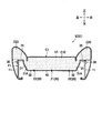
図1に示すように、本実施形態の乗物用シートは、自動車に搭載される車両用シートSとして構成されており、シートクッションS1と、シートバックS2と、ヘッドレストS3とを備えている。
Hereinafter, an embodiment of the invention will be described with reference to the accompanying drawings. In this specification, the front / rear, left / right, and up / down are based on the front / rear, left / right, and up / down as seen from the person sitting on the vehicle seat (seat person).
As shown in FIG. 1, the vehicle seat of the present embodiment is configured as a vehicle seat S mounted on an automobile, and includes a seat cushion S1, a seat back S2, and a headrest S3.
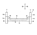
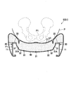
シートクッションS1の内部には、図2に示すようなクッションフレームF1が内蔵されている。クッションフレームF1は、シートクッションS1の骨格を構成する部材である。図3に示すように、シートクッションS1は、クッションフレームF1に、ウレタンフォームなどからなるクッションパッドC1と、布地や皮革などからなる表皮材U1を被せることで構成されている。 A cushion frame F1 as shown in FIG. 2 is built in the seat cushion S1. The cushion frame F1 is a member that constitutes the skeleton of the seat cushion S1. As shown in FIG. 3, the seat cushion S1 is configured by covering the cushion frame F1 with a cushion pad C1 made of urethane foam or the like and a skin material U1 made of cloth or leather.
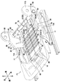
図2に示すように、クッションフレームF1は、左右のサイドフレーム11と、前後のクロスメンバの一例としてのフロントフレーム12およびリアフレーム13と、パンフレーム14とを有している。
As shown in FIG. 2, the cushion frame F1 has left and right side frames 11, a
左右のサイドフレーム11は、金属板から形成されたフレームであり、左右に離間して配置されている。各サイドフレーム11は、略前後方向に延びるサイドフレーム本体11Aと、サイドフレーム本体11Aの後端部から略上方に延びるバック取付部11Bとを有し、周縁部が左右方向内側に延出した断面形状をなしている。バック取付部11Bには、シートバックS2の骨格を構成する図示しないバックフレームがリクライニング機構を介して回動可能に取り付けられる。なお、シートバックS2は、シートクッションS1と同様に、バックフレームに、ウレタンフォームなどからなるパッド材と、表皮材を被せることで構成されている。
The left and right side frames 11 are frames formed of a metal plate, and are arranged so as to be separated from each other on the left and right. Each
フロントフレーム12とリアフレーム13は、金属製のパイプ材から形成されたフレームであり、前後に離間して配置されている。フロントフレーム12は、左右のサイドフレーム11(サイドフレーム本体11A)の前部同士を連結しており、リアフレーム13は、左右のサイドフレーム11(サイドフレーム本体11A)の後部同士を連結している。
パンフレーム14は、金属板から形成されたフレームであり、左右のサイドフレーム11の前端部同士を連結するように配置されている。
The
The
左右のサイドフレーム11の間には、クッションパッドC1(図3参照)を下から支持する3つの支持ワイヤ20が配置されている。各支持ワイヤ20は、フロントフレーム12とリアフレーム13に架設されて前後方向に延びるように配置されている。支持ワイヤ20は、金属製の線材から形成されている。支持ワイヤ20の前端は、前斜め上方に屈曲して延びた後、フロントフレーム12の外周面に沿うように略円弧状に曲げられている。また、支持ワイヤ20の後端は、上方に屈曲して延びた後、リアフレーム13の外周面に沿うように略円弧状に曲げられている。
Three
支持ワイヤ20は、1つの第1支持ワイヤ21と、左右の線状部材の一例としての2つの第2支持ワイヤ22とを含んでいる。第1支持ワイヤ21は、クッションフレームF1の内側の左右方向中央に配置されている。また、左右の第2支持ワイヤ22は、クッションフレームF1の内側で第1支持ワイヤ21の左右両側に1つずつ配置されている。言い換えると、左右の第2支持ワイヤ22は、左右に離間して配置されており、その間に第1支持ワイヤ21が配置されている。
The
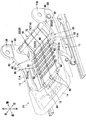
支持ワイヤ20の左右両側には、第1支持部材の一例としてのサイド支持部材30が配置されている。左右のサイド支持部材30は、支持ワイヤ20とともにクッションパッドC1(図3参照)を支持する部材であり、樹脂からなる。図4に示すように、左右のサイド支持部材30は、着座者のヒップポイントHPの左右に1つずつ配置されている。各サイド支持部材30は、前後方向においてヒップポイントHPを含む範囲に配置されている。言い換えると、サイド支持部材30は、ヒップポイントHPの左右両側で、上下方向から見てヒップポイントHPを挟むように配置されている。なお、本明細書において、ヒップポイントHPは、SAE J−826に基づく3Dマネキンをシートに着座させたときのヒップポイントの位置である。図2に示すように、各サイド支持部材30は、支持部の一例としてサイド支持部31と、接続部32と、係合部33とを有している。
サイド支持部31は、サイドフレーム11よりも左右方向内側に位置する板状の部分であり、左右方向外側にいくほど上に位置するように傾斜した状態で配置されている。各サイド支持部31は、前後方向の幅が、左右方向内側にいくほど大きくなる略台形状をなしている(図4も参照)。サイド支持部31は、一例として、前後方向の幅が10cm以上であることが望ましい。詳しくは、サイド支持部31は、前後方向の幅が最も小さい上端の幅が10cm以上であることが望ましい。
The
各サイド支持部31は、上側の面である第1支持面31Aを有している。本実施形態において、第1支持面31Aは、板状のサイド支持部31が左右外側にいくほど上に位置するように傾斜して配置されていることで、左右方向外側にいくほど上に位置する傾斜面となっている。また、各サイド支持部31の下端部は、三叉状に分岐している。
Each
接続部32は、サイド支持部31の下端、詳しくは、三叉状に分岐した部分の先端のそれぞれから、左右方向内側に延びるように設けられている。接続部32の左右方向内側の端部は、第2支持ワイヤ22に連結されている。詳しくは、接続部32は、図3に示すように、左右方向内側の端部が、第2支持ワイヤ22の一部の全周を覆った状態で、第2支持ワイヤ22の一部を包むように設けられている。言い換えると、第2支持ワイヤ22は、接続部32の左右方向内側の端部を貫通するように配置されている。樹脂製のサイド支持部材30は、このように接続部32が第2支持ワイヤ22に連結されていることで、金属製の第2支持ワイヤ22と一体に形成されている。
The connecting
係合部33は、サイドフレーム11に係合する部分である。詳しくは、係合部33は、サイド支持部31の上端から上方に延びた後、サイドフレーム11の上面に沿って左右方向外側に延び、さらに下方に延びる略U字の断面形状(フック形状)をなしている。係合部33は、サイドフレーム11の上端部に上から引っ掛かることにより、サイドフレーム11に係合する。
The engaging
本実施形態において、左右のサイド支持部材30は、連結部40でつながっている。連結部40は、樹脂からなる略板状の部材であり、左右のサイド支持部材30の接続部32の間で左右に延びるように配置されている。連結部40は、サイド支持部材30の接続部32と一体に形成されて左右のサイド支持部材30をつないでいる。
In the present embodiment, the left and right
図2に示すように、連結部40は、前後に並ぶ3組の接続部32に対応して1つずつ、合計3つ設けられている。各連結部40の左右方向中央部は、第1支持ワイヤ21に連結されて第1支持ワイヤ21と一体に形成されている。詳しくは、各連結部40は、左右方向中央部が、第1支持ワイヤ21の一部の全周を覆った状態で、第1支持ワイヤ21の一部を包むように設けられている(図3も参照)。言い換えると、第1支持ワイヤ21は、各連結部40の左右方向中央部を貫通するように配置されている。
As shown in FIG. 2, a total of three connecting
また、本実施形態において、3つの支持ワイヤ20は、前後に並ぶ複数のワイヤ連結部材50によって連結部40よりも前側の部分同士が連結されている。ワイヤ連結部材50は、樹脂からなる略板状の部材である。各ワイヤ連結部材50は、左右方向中央部が、第1支持ワイヤ21の一部の全周を覆った状態で、第1支持ワイヤ21の一部を包むように設けられている。また、各ワイヤ連結部材50は、左右方向両端部が、第2支持ワイヤ22の一部の全周を覆った状態で、第2支持ワイヤ22の一部を包むように設けられている。これにより、第1支持ワイヤ21は、各ワイヤ連結部材50の左右方向中央部を貫通するように配置され、第2支持ワイヤ22は、各ワイヤ連結部材50の左右方向両端部を貫通するように配置されている。
Further, in the present embodiment, the three
なお、サイド支持部材30の接続部32、連結部40およびワイヤ連結部材50には、上下に貫通した略矩形の貫通孔(符号省略)が形成されている。本実施形態の車両用シートSは、接続部32、連結部40およびワイヤ連結部材50の貫通孔に、ワイヤハーネスなどを留めるためのクリップを係合させることで、ワイヤハーネスなどを取付可能となっている。言い換えると、接続部32、連結部40およびワイヤ連結部材50は、ワイヤハーネスなどが取り付けられる取付座となっている。
The connecting
3つの支持ワイヤ20の前部には、それぞれ被覆部材60が配置されている。被覆部材60は、樹脂からなり、支持ワイヤ20の前端の略円弧状に曲げられた部分を覆って包むように設けられて支持ワイヤ20と一体に形成されている。被覆部材60は、左右方向にわたって切れ目が形成されたような略C字の筒状をなしている。各支持ワイヤ20の前端は、被覆部材60に覆われた状態でフロントフレーム12に掛止されている。
A covering
また、3つの支持ワイヤ20の後部には、第2支持部材の一例としてのリア支持部材70が配置されている。リア支持部材70は、支持ワイヤ20やサイド支持部材30とともにクッションパッドC1を支持する部材であり、樹脂からなる。リア支持部材70は、左右の第2支持ワイヤ22を含む支持ワイヤ20の後端部を覆って包むように設けられて支持ワイヤ20と一体に形成されている。リア支持部材70は、リア支持部71と、掛止部72とを有している。
Further, a
リア支持部71は、後側のクロスメンバであるリアフレーム13よりも前側に位置する板状の部分であり、左右方向から見て略L字形状をなしている。
掛止部72は、支持ワイヤ20の後端を覆う部分であり、左右方向から見て略U字形状をなしている。
リア支持部71と掛止部72の後端部とは、左右に延びており、左右の第2支持ワイヤ22を含む3つの支持ワイヤ20の後端部同士を連結している。
The
The
The
各支持ワイヤ20の後端は、リア支持部材70の掛止部72に覆われた状態でリアフレーム13に掛止されている。本実施形態の車両用シートSにおいては、金属製の支持ワイヤ20の前端が樹脂製の被覆部材60に覆われた状態で金属製のフロントフレーム12に掛止され、後端が樹脂製の掛止部72に覆われた状態で金属製のリアフレーム13に掛止されているので、金属製の部材同士の接触音が発生しないようになっている。
The rear end of each
以上説明した、金属からなる支持ワイヤ20と、樹脂からなるサイド支持部材30、連結部40、ワイヤ連結部材50、被覆部材60およびリア支持部材70とは、例えば、インサート成形により一体に形成されている。
The
各サイドフレーム11の後端部は、例えば、人が金属製のサイドフレーム11に触れることができないように、それぞれカバー部材80によって覆われている。左右のカバー部材80は、樹脂からなり、それぞれインナカバー部81と、アッパカバー部82と、リアカバー部83とを有している。
The rear end portion of each
インナカバー部81は、サイドフレーム11の後端部の左右方向内側を覆う部分である。インナカバー部81は、バック取付部11Bの下側の位置であって、サイド支持部材30の後側の位置からサイドフレーム本体11Aの後縁部までの範囲にわたるように配置されている。
The
アッパカバー部82は、サイドフレーム11の後端部のバック取付部11Bよりも前側の部分を上側から覆う部分であり、インナカバー部81の上端の前側部分から左右方向外側に延びるように設けられている。本実施形態において、アッパカバー部82は、左右方向外側の端部がサイドフレーム11の側面に沿うように下方に延びていることで略L字の断面形状をなしており、インナカバー部81とともにフック形状を形成している。カバー部材80は、インナカバー部81およびアッパカバー部82によって形成されるフック形状部分がサイドフレーム11の上端部に上から引っ掛かることにより、サイドフレーム11に係合している。
The
リアカバー部83は、図5に示すように、サイドフレーム11の後端を後側から覆う部分であり、インナカバー部81の後端から左右方向外側に延びるように設けられている。
As shown in FIG. 5, the
図4に示すように、クッションパッドC1は、中央部C10と、中央部C10の左右両側に設けられて中央部C10よりも上側に張り出した左右の側部C20とを有している。また、クッションパッドC1は、表皮材U1(図3参照)を吊り込むための吊り込み溝C30を有している。 As shown in FIG. 4, the cushion pad C1 has a central portion C10 and left and right side portions C20 provided on both left and right sides of the central portion C10 and projecting above the central portion C10. Further, the cushion pad C1 has a hanging groove C30 for hanging the skin material U1 (see FIG. 3).
吊り込み溝C30は、前後方向に延びる左右の第1溝C31と、左右方向に延びる第2溝C32および第3溝C33とを含んでいる。
左右の第1溝C31は、ヒップポイントHPの左右両側において、中央部C10と各側部C20との境界部に沿って延びるように形成されている。
第2溝C32は、ヒップポイントHPの前側において、左右の第1溝C31の前後方向中央部付近同士をつなぐように形成されている。
第3溝C33は、ヒップポイントHPの後側において、左右の第1溝C31の後部同士をつなぐように形成されている。
The suspension groove C30 includes left and right first grooves C31 extending in the front-rear direction, and second grooves C32 and third grooves C33 extending in the left-right direction.
The left and right first grooves C31 are formed so as to extend along the boundary between the central portion C10 and each side portion C20 on both the left and right sides of the hip point HP.
The second groove C32 is formed on the front side of the hip point HP so as to connect the vicinity of the central portion in the front-rear direction of the left and right first grooves C31.
The third groove C33 is formed on the rear side of the hip point HP so as to connect the rear portions of the left and right first grooves C31.
また、クッションパッドC1には、表皮材U1を吊り込み溝C30内に吊り込むための図示しない吊りワイヤがインサート成形により埋設されている。吊りワイヤは、吊り込み溝C30に沿うように配置され、吊り込み溝C30の底部に形成された複数の穴C50から部分的に露出している。表皮材U1は、当該表皮材U1に設けられた図示しないフックを、吊りワイヤの穴C50から露出した部分に係合させることでクッションパッドC1に留められている。 Further, in the cushion pad C1, a suspension wire (not shown) for suspending the skin material U1 into the suspension groove C30 is embedded by insert molding. The suspension wire is arranged along the suspension groove C30 and is partially exposed from a plurality of holes C50 formed in the bottom of the suspension groove C30. The skin material U1 is fastened to the cushion pad C1 by engaging a hook (not shown) provided on the skin material U1 with a portion exposed from the hole C50 of the hanging wire.
サイド支持部材30のサイド支持部31は、左右方向において、対応する第1溝C31をまたぐように、第1溝C31の下に配置されている。すなわち、サイド支持部31と第1溝C31とは、交差するように配置されている。また、サイド支持部31は、前後方向において、第2溝C32と第3溝C33の間の位置に配置されている。
The
次に、以上のように構成された車両用シートSの作用効果について説明する。
図6に示すように、車両用シートSに人(着座者P)が座ると、ヒップポイントHPの左右両側でヒップポイントHPを挟むように配置された左右のサイド支持部材30のサイド支持部31によって着座者Pの臀部および大腿部の側部を左右外側から挟むように支持することができる。これにより、サイド支持部31が配置されていない場合と比較して、着座者Pの臀部および大腿部の側部をしっかりと支えることができる。その結果、坐骨P1(正確には、坐骨P1の最も下に突出したところ。以下同様。)の周辺の圧力が相対的に下がるので、坐骨P1の周辺と臀部および大腿部の全体で着座者Pをバランス良く支持することができる。これにより、着座者Pの坐骨P1の周辺の血行が悪くなりにくくなるので、長時間座っても着座者Pの疲労感を少なくすることができる。
Next, the action and effect of the vehicle seat S configured as described above will be described.
As shown in FIG. 6, when a person (seat P) sits on the vehicle seat S, the
また、第2支持ワイヤ22と一体に形成された左右のサイド支持部材30が、サイドフレーム11に係合する係合部33を有するので、第2支持ワイヤ22などをフロントフレーム12とリアフレーム13に架設し、係合部33をサイドフレーム11に係合することで、支持ワイヤ20とサイド支持部材30の両方をクッションフレームF1に取り付けることができる。これにより、支持ワイヤとは別にサイド支持部材を取付位置に配置したり、サイド支持部材をねじなどで固定したりする必要がなくなるため、車両用シートSの組立工数を減らすことができる。
Further, since the left and right
また、サイド支持部材30の第1支持面31Aが左右外側にいくほど上に位置する傾斜面なので、前後方向から見て、支持ワイヤ20と左右の第1支持面31Aとによって人体(着座者P)の形状に沿った凹形状を形成することができる。これにより、着座者Pが車両用シートSに座ったときに、着座者Pを安定して支持することができるので、快適な座り心地を実現することができる。
Further, since the
また、サイド支持部31の前後方向の幅が左右内側にいくほど大きくなっていることで、サイド支持部31の左右外側の前後幅が相対的に小さくなり、サイド支持部31を上下に適度に撓ませることが可能となるため、適度なクッション性を持たせることができる。また、サイド支持部31の左右内側の前後幅が相対的に大きくなるので、荷重を幅の大きい部分で支持することができるため、着座者Pを安定して支持することができる。これにより、着座者Pが車両用シートSに座ったときにより快適な座り心地を実現することができる。なお、サイド支持部31の前後幅が最も小さい上端の前後幅を10cm以上とすることで、サイド支持部31の、撓む際に大きな荷重がかかる上端付近の強度を向上させることができる。
Further, since the width of the
また、係合部33がサイドフレーム11に上から引っ掛かることによってサイドフレーム11に係合するので、サイド支持部材30をクッションフレームF1に容易に取り付けることができる。
Further, since the engaging
また、左右のサイド支持部材30が連結部40でつながって一体に形成されているので、左右のサイド支持部材30と支持ワイヤ20を一体の部品として取り扱うことができる。これにより、左右のサイド支持部材をそれぞれ配置して取り付ける場合と比較して、車両用シートSの組立工数をより減らすことができる。
Further, since the left and right
また、支持ワイヤ20の後端部がリア支持部材70によって連結されているので、これによっても、支持ワイヤ20と左右のサイド支持部材30を一体の部品として取り扱うことができる。これにより、複数の支持ワイヤの後端部を1つずつリアフレーム13に掛止する場合と比較して、車両用シートSの組立工数をより減らすことができる。
Further, since the rear end portion of the
また、左右のサイド支持部材30が連結部40やリア支持部材70などでつながって一体に形成されているので、支持ワイヤ20、左右のサイド支持部材30およびリア支持部材70を一体の部品として取り扱いやすくなっている。これにより、これらをクッションフレームF1に容易に取り付けることができる。
Further, since the left and right
以上、発明の一実施形態について説明したが、本発明は前記実施形態に限定されるものではない。具体的な構成については、下記のように発明の趣旨を逸脱しない範囲で適宜変更が可能である。なお、以下では、先に説明した構成と同様の構成については同一符号を付して適宜説明を省略し、先に説明した構成と異なる点について詳細に説明する。 Although one embodiment of the invention has been described above, the present invention is not limited to the above embodiment. The specific configuration can be appropriately changed as described below without departing from the spirit of the invention. In the following, the same configurations as those described above will be designated by the same reference numerals, and the description thereof will be omitted as appropriate, and the points different from the configurations described above will be described in detail.
例えば、図7および図8に示すように、支持ワイヤ20の後部が、後斜め上方に屈曲して延びた後、リアフレーム13の外周面に沿うように略円弧状に曲げられている構成で、リア支持部材70の板状のリア支持部71は、後にいくほど上に位置するように傾斜した状態で配置されていてもよい。さらに説明すると、図7および図8に示す形態では、リア支持部材70のリア支持部71は、上側の面である第2支持面71Aを有している。第2支持面71Aは、板状のリア支持部71が後にいくほど上に位置するように傾斜して配置されていることで、後にいくほど上に位置する傾斜面となっている。このような構成によれば、左右方向から見て支持ワイヤ20と第2支持面71Aとによって人体の形状に沿った形状が形成されるので、着座者がシートクッションS1に座ったときに、着座者Pを安定して支持することができ、快適な座り心地を実現することができる。
For example, as shown in FIGS. 7 and 8, the rear portion of the
また、図9に示すように、左右のサイド支持部材30は、リア支持部材70とつながって一体に形成されていてもよい。詳しくは、左右のサイド支持部材30は、サイド支持部31とリア支持部71とが板状のサイド連結部90によってつながっている。サイド連結部90は、上側の面である第3支持面90Aを有しており、第3支持面90Aは、クッションフレームF1の外側に行くほど上に位置する傾斜面となっていて、第1支持面31Aと第2支持面71Aをなめらかにつないでいる。このような構成によれば、左右のサイド支持部材30、リア支持部材70および支持ワイヤ20を一体の部品として取り扱いやすくなるので、これらをクッションフレームF1に容易に取り付けることができる。
Further, as shown in FIG. 9, the left and right
また、図10に示すように、サイド支持部材30は、カバー部材80とつながって一体に形成されていてもよい。詳しくは、左右のサイド支持部材30は、係合部33の後端が、カバー部材80のアッパカバー部82の前端とつながって一体に形成されている。このような構成によれば、カバー部材80、サイド支持部材30および支持ワイヤ20を一体の部品として取り扱えるので、車両用シートSの組立工数をより減らすことができる。
Further, as shown in FIG. 10, the
また、前記実施形態では、カバー部材80が、インナカバー部81、アッパカバー部82およびリアカバー部83を有していたが、これに限定されない。例えば、カバー部材は、インナカバー部81とリアカバー部83を有し、アッパカバー部82を備えないものであってもよいし、インナカバー部81とアッパカバー部82を有し、リアカバー部83を備えないものであってもよい。また、カバー部材は、インナカバー部81を有し、アッパカバー部82およびリアカバー部83を備えないものであってもよい。すなわち、カバー部材は、サイドフレームの後端部の少なくとも左右方向内側を覆う部材であればよい。
Further, in the above-described embodiment, the
また、前記実施形態では、車両用シートSが支持ワイヤ20を連結するリア支持部材70を備えていたが、これに限定されない。例えば、車両用シートは、リア支持部材を備えないものであってもよい。この場合であっても、支持ワイヤの、リアフレームに掛止される後端は、樹脂製の部材で覆われていることが望ましい。これによれば、金属製の部材同士が接触することによって発生する接触音を防ぐことができる。
Further, in the above-described embodiment, the vehicle seat S includes a
また、前記実施形態では、左右のサイド支持部材30が連結部40でつながって一体に形成されていたが、これに限定されず、例えば、左右のサイド支持部材は、つながっていない構成であってもよい。
Further, in the above-described embodiment, the left and right
また、前記実施形態では、係合部33が、サイドフレーム11に上から引っ掛かる構成であったが、これに限定されない。例えば、係合部は、サイドフレームに形成された穴に係合する構成であってもよい。また、係合部は、サイドフレームに形成されたフック状の部分に係合する構成などであってもよい。
Further, in the above-described embodiment, the engaging
また、前記実施形態では、サイド支持部31は、前後方向の幅が左右方向内側にいくほど大きくなる略台形状をなしていたが、これに限定されない。例えば、サイド支持部は、その全体ではなく、一部の前後方向の幅が左右方向内側にいくほど大きくなっている形状であってもよい。また、サイド支持部は、前後方向の幅がほとんど変化しない、例えば、略矩形状をなしていてもよい。
Further, in the above-described embodiment, the
また、前記実施形態では、第1支持面31Aを有するサイド支持部31が板状であったが、これに限定されない。例えば、サイド支持部は、前後方向に沿って見た断面で、略三角形状をなすような厚みを有するものであってもよい。
Further, in the above-described embodiment, the
また、前記実施形態では、第1支持面31Aが左右外側にいくほど上に位置する傾斜面であったが、これに限定されず、例えば、第1支持面は、上を向いた面などであってもよい。なお、第1支持面は、平面であってもよいし、曲面であってもよい。
Further, in the above-described embodiment, the
また、前記実施形態では、第1支持部材としてのサイド支持部材30や、第2支持部材としてのリア支持部材70が、支持ワイヤ20の一部の全周を覆って包むように設けられて支持ワイヤ20と一体に形成されていたが、これに限定されない。例えば、第1支持部材や第2支持部材は、断面視U字状やC字状の部分が支持ワイヤの一部に係合することで支持ワイヤと一体に形成されていてもよい。すなわち、第1支持部材や第2支持部材は、支持ワイヤ20の全周を覆っていない(包んでいない)構成であってもよい。
Further, in the above-described embodiment, the
また、前記実施形態では、第1支持ワイヤ21が左右方向中央に1つだけ配置されていたが、これに限定されず、例えば、左右方向に並んで複数配置されていてもよい。また、前記実施形態では、線状部材として第2支持ワイヤ22(支持ワイヤ20)を例示したが、これに限定されず、例えば、線状部材は、Sバネのような、少なくとも一部が左右方向に交互に屈曲した弾性変形可能な部材などであってもよい。
Further, in the above-described embodiment, only one
また、前記実施形態では、前後のクロスメンバとしてフロントフレーム12およびリアフレーム13を例示したが、これに限定されない。例えば、前側のクロスメンバは、図2に示したパンフレーム14などであってもよい。また、後側のクロスメンバは、パイプ材から形成された部材ではなく、金属板から形成された部材などであってもよい。また、前記実施形態では、サイドフレームとして、金属板から形成されたものを例示したが、これに限定されず、例えば、パイプ材などから形成されたものであってもよい。
Further, in the above-described embodiment, the
また、前記実施形態では、乗物用シートとして自動車に搭載される車両用シートSを例示したが、これに限定されず、自動車以外の乗物、例えば、鉄道車両や船舶、航空機などに搭載されるシートであってもよい。 Further, in the above-described embodiment, the vehicle seat S mounted on an automobile is exemplified as a vehicle seat, but the present invention is not limited to this, and a seat mounted on a vehicle other than an automobile, for example, a railroad vehicle, a ship, an aircraft, or the like. It may be.
また、前記した実施形態および変形例で説明した各要素を、任意に組み合わせて実施してもよい。 In addition, each element described in the above-described embodiment and modification may be arbitrarily combined and implemented.
11 サイドフレーム
12 フロントフレーム
13 リアフレーム
22 第2支持ワイヤ
30 サイド支持部材
31 サイド支持部
31A 第1支持面
33 係合部
40 連結部
70 リア支持部材
71A 第2支持面
80 カバー部材
F1 クッションフレーム
S 車両用シート
11
Claims (7)
左右に離間して配置され、前記前後のクロスメンバに架設された左右の線状部材と、
前記クッションフレームに被せられたクッションパッドと、
前記クッションパッドに被せられた表皮材と、
樹脂からなり、前記線状部材と一体に形成された左右の第1支持部材と、を備え、
前記クッションパッドは、前記表皮材を吊り込むための吊り込み溝を有し、
前記第1支持部材は、前記サイドフレームに係合する係合部を有するとともに、左右方向において、前記吊り込み溝をまたぐように配置され、左右方向において、前記吊り込み溝より内側の部分が、前記吊り込み溝より外側の部分よりも大きいことを特徴とする乗物用シート。 A cushion frame having left and right side frames arranged apart from each other on the left and right, and front and rear cross members connecting the left and right side frames.
The left and right linear members, which are arranged apart from each other on the left and right and erected on the front and rear cross members,
The cushion pad over the cushion frame and
The skin material covered on the cushion pad and
The left and right first support members made of resin and integrally formed with the linear member are provided.
The cushion pad has a hanging groove for hanging the skin material, and has a hanging groove.
The first support member has an engaging portion that engages with the side frame, and is arranged so as to straddle the suspension groove in the left-right direction, and a portion inside the suspension groove in the left-right direction is formed. A vehicle seat characterized in that it is larger than a portion outside the hanging groove.
左右に離間して配置され、前記前後のクロスメンバに架設された左右の線状部材と、
前記クッションフレームに被せられたクッションパッドと、
前記クッションパッドに被せられた表皮材と、
樹脂からなり、前記線状部材と一体に形成された左右の第1支持部材と、を備え、
前記クッションパッドは、前記表皮材を吊り込むための吊り込み溝を有し、
前記第1支持部材は、左右方向において外側にいくほど上に位置するように傾斜する第1支持面を有し、前記吊り込み溝をまたぐように配置され、左右方向において、前記吊り込み溝より内側の部分が、前記吊り込み溝より外側の部分よりも大きいことを特徴とする乗物用シート。 A cushion frame having left and right side frames arranged apart from each other on the left and right, and front and rear cross members connecting the left and right side frames.
The left and right linear members, which are arranged apart from each other on the left and right and erected on the front and rear cross members,
The cushion pad over the cushion frame and
The skin material covered on the cushion pad and
The left and right first support members made of resin and integrally formed with the linear member are provided.
The cushion pad has a hanging groove for hanging the skin material, and has a hanging groove.
The first support member has a first support surface that is inclined so as to be located upward toward the outside in the left-right direction, is arranged so as to straddle the suspension groove, and is arranged from the suspension groove in the left-right direction. A vehicle seat characterized in that the inner portion is larger than the outer portion of the hanging groove.
前記第1支持部材は、上から見て、前記第1溝と重なり、前記第2溝と重ならないことを特徴とする請求項1から請求項4のいずれか1項に記載の乗物用シート。 The hanging groove includes a first groove extending in the front-rear direction and a second groove extending in the left-right direction.
The vehicle seat according to any one of claims 1 to 4, wherein the first support member overlaps with the first groove and does not overlap with the second groove when viewed from above.
前記第1支持部材は、前記第2溝より後ろで、かつ、前記第3溝より前に位置することを特徴とする請求項5に記載の乗物用シート。 The hanging groove is located behind the second groove and further includes a third groove extending in the left-right direction.
The vehicle seat according to claim 5, wherein the first support member is located behind the second groove and before the third groove.
前記シートバックは、シートバックフレームと、当該シートバックフレームに被せられるパッド材および表皮材と、を備えて構成されることを特徴とする請求項1から請求項6のいずれか1項に記載の乗物用シート。 With a seat back and a headrest,
The method according to any one of claims 1 to 6 , wherein the seat back includes a seat back frame, a pad material and a skin material that cover the seat back frame. Vehicle seat.
Priority Applications (1)
| Application Number | Priority Date | Filing Date | Title |
|---|---|---|---|
| JP2019075607A JP6920622B2 (en) | 2017-02-23 | 2019-04-11 | Vehicle seat |
Applications Claiming Priority (2)
| Application Number | Priority Date | Filing Date | Title |
|---|---|---|---|
| JP2017032689A JP6513726B2 (en) | 2017-02-23 | 2017-02-23 | Vehicle seat |
| JP2019075607A JP6920622B2 (en) | 2017-02-23 | 2019-04-11 | Vehicle seat |
Related Parent Applications (1)
| Application Number | Title | Priority Date | Filing Date |
|---|---|---|---|
| JP2017032689A Division JP6513726B2 (en) | 2017-02-23 | 2017-02-23 | Vehicle seat |
Publications (3)
| Publication Number | Publication Date |
|---|---|
| JP2019108128A JP2019108128A (en) | 2019-07-04 |
| JP2019108128A5 JP2019108128A5 (en) | 2019-12-26 |
| JP6920622B2 true JP6920622B2 (en) | 2021-08-18 |
Family
ID=67178884
Family Applications (1)
| Application Number | Title | Priority Date | Filing Date |
|---|---|---|---|
| JP2019075607A Active JP6920622B2 (en) | 2017-02-23 | 2019-04-11 | Vehicle seat |
Country Status (1)
| Country | Link |
|---|---|
| JP (1) | JP6920622B2 (en) |
Family Cites Families (3)
| Publication number | Priority date | Publication date | Assignee | Title |
|---|---|---|---|---|
| JPS5638665U (en) * | 1979-09-04 | 1981-04-11 | ||
| JP6085546B2 (en) * | 2013-09-26 | 2017-02-22 | 日本発條株式会社 | Vehicle seat and trim cover |
| JP6446284B2 (en) * | 2015-02-06 | 2018-12-26 | テイ・エス テック株式会社 | Vehicle seat |
-
2019
- 2019-04-11 JP JP2019075607A patent/JP6920622B2/en active Active
Also Published As
| Publication number | Publication date |
|---|---|
| JP2019108128A (en) | 2019-07-04 |
Similar Documents
| Publication | Publication Date | Title |
|---|---|---|
| US9028004B2 (en) | Vehicle seat | |
| JP7112005B2 (en) | seat | |
| JP6085546B2 (en) | Vehicle seat and trim cover | |
| WO2018154828A1 (en) | Seat | |
| JP6495358B2 (en) | Vehicle seat | |
| JP6669973B2 (en) | Sheet | |
| JP6920622B2 (en) | Vehicle seat | |
| JP6898571B2 (en) | Vehicle seat | |
| JP5861570B2 (en) | Vehicle seat | |
| JP6513726B2 (en) | Vehicle seat | |
| CN112848990B (en) | Vehicle seat | |
| JP2021181302A (en) | Vehicle seat | |
| JP7085134B2 (en) | Vehicle seat | |
| JP6053465B2 (en) | Vehicle seat | |
| JP7453565B2 (en) | sheet | |
| JP6492918B2 (en) | Vehicle seat cover and vehicle seat | |
| JP7193704B2 (en) | vehicle seat | |
| JP7077041B2 (en) | Vehicle seat | |
| JP7106857B2 (en) | vehicle seat | |
| JP2020124980A (en) | Vehicular seat | |
| JP6433055B2 (en) | Chair | |
| CN111845491A (en) | Chair back | |
| JP2011147550A (en) | Vehicle seat |
Legal Events
| Date | Code | Title | Description |
|---|---|---|---|
| A521 | Written amendment |
Free format text: JAPANESE INTERMEDIATE CODE: A523 Effective date: 20191115 |
|
| A621 | Written request for application examination |
Free format text: JAPANESE INTERMEDIATE CODE: A621 Effective date: 20200221 |
|
| A977 | Report on retrieval |
Free format text: JAPANESE INTERMEDIATE CODE: A971007 Effective date: 20201209 |
|
| A131 | Notification of reasons for refusal |
Free format text: JAPANESE INTERMEDIATE CODE: A131 Effective date: 20201215 |
|
| A601 | Written request for extension of time |
Free format text: JAPANESE INTERMEDIATE CODE: A601 Effective date: 20210126 |
|
| A521 | Written amendment |
Free format text: JAPANESE INTERMEDIATE CODE: A523 Effective date: 20210406 |
|
| TRDD | Decision of grant or rejection written | ||
| A01 | Written decision to grant a patent or to grant a registration (utility model) |
Free format text: JAPANESE INTERMEDIATE CODE: A01 Effective date: 20210622 |
|
| A61 | First payment of annual fees (during grant procedure) |
Free format text: JAPANESE INTERMEDIATE CODE: A61 Effective date: 20210705 |
|
| R150 | Certificate of patent or registration of utility model |
Ref document number: 6920622 Country of ref document: JP Free format text: JAPANESE INTERMEDIATE CODE: R150 |