JP6433055B2 - Chair - Google Patents
Chair Download PDFInfo
- Publication number
- JP6433055B2 JP6433055B2 JP2014213598A JP2014213598A JP6433055B2 JP 6433055 B2 JP6433055 B2 JP 6433055B2 JP 2014213598 A JP2014213598 A JP 2014213598A JP 2014213598 A JP2014213598 A JP 2014213598A JP 6433055 B2 JP6433055 B2 JP 6433055B2
- Authority
- JP
- Japan
- Prior art keywords
- frame
- seat
- chair
- leg
- backrest
- Prior art date
- Legal status (The legal status is an assumption and is not a legal conclusion. Google has not performed a legal analysis and makes no representation as to the accuracy of the status listed.)
- Active
Links
Images


Classifications
-
- A—HUMAN NECESSITIES
- A47—FURNITURE; DOMESTIC ARTICLES OR APPLIANCES; COFFEE MILLS; SPICE MILLS; SUCTION CLEANERS IN GENERAL
- A47C—CHAIRS; SOFAS; BEDS
- A47C11/00—Benches not otherwise provided for
- A47C11/005—Benches not otherwise provided for having multiple separate seats
-
- A—HUMAN NECESSITIES
- A47—FURNITURE; DOMESTIC ARTICLES OR APPLIANCES; COFFEE MILLS; SPICE MILLS; SUCTION CLEANERS IN GENERAL
- A47C—CHAIRS; SOFAS; BEDS
- A47C1/00—Chairs adapted for special purposes
- A47C1/12—Theatre, auditorium, or similar chairs
-
- A—HUMAN NECESSITIES
- A47—FURNITURE; DOMESTIC ARTICLES OR APPLIANCES; COFFEE MILLS; SPICE MILLS; SUCTION CLEANERS IN GENERAL
- A47C—CHAIRS; SOFAS; BEDS
- A47C1/00—Chairs adapted for special purposes
- A47C1/12—Theatre, auditorium, or similar chairs
- A47C1/124—Separate chairs, connectible together into a row
-
- A—HUMAN NECESSITIES
- A47—FURNITURE; DOMESTIC ARTICLES OR APPLIANCES; COFFEE MILLS; SPICE MILLS; SUCTION CLEANERS IN GENERAL
- A47C—CHAIRS; SOFAS; BEDS
- A47C1/00—Chairs adapted for special purposes
- A47C1/16—Chairs or seats detachably mounted on stadium benches
-
- A—HUMAN NECESSITIES
- A47—FURNITURE; DOMESTIC ARTICLES OR APPLIANCES; COFFEE MILLS; SPICE MILLS; SUCTION CLEANERS IN GENERAL
- A47C—CHAIRS; SOFAS; BEDS
- A47C4/00—Foldable, collapsible or dismountable chairs
- A47C4/02—Dismountable chairs
Description
この発明は、例えば、公共施設の待合室等で用いられる椅子に関するものである。 The present invention relates to a chair used in a waiting room of a public facility, for example.
公共施設の待合室等で用いられる椅子として、略水平に延出する支持杆に、座を有する椅子本体が複数並列に並んで設置されたものが知られている(例えば、特許文献1,2参照)。
As a chair used in a waiting room of a public facility, a chair in which a plurality of chair bodies having a seat are arranged in parallel on a supporting rod extending substantially horizontally is known (see, for example,
特許文献1に記載の椅子は、断面矩形状の支持杆が一対の脚体によって略水平に支持され、その支持杆の長手方向の適所に椅子本体が溶接やボルト締結によって固定されている。椅子本体は、座の骨格を成す座フレームの下面に金属製の連結脚(ブラケット)が固定され、その連結脚の下端領域に形成された嵌合凹部が支持杆の略上半部に嵌合され、その状態で支持杆に対して溶接やボルト締結によって固定されている。また、椅子本体は、相互に固定される座と背凭れとを有し、座と背凭れは、いずれもフレームにスプリングやクッション材が取り付けられ、クッション材の外側が表皮材によって覆われた構造とされている。
In the chair described in
特許文献2に記載の椅子は、特許文献1に記載の椅子と同様に、連結脚の嵌合凹部が断面矩形状の支持杆に嵌合状態で固定されるものであるが、連結脚の下端部から座の側部フレームに接続される上端部に向かって水平断面が滑らかに漸増する形状とされるとともに、側部フレームと連結脚とが同様の剛体によって形成され、両者が上下方向に沿うボルトによって相互に結合されている。
Similarly to the chair described in
この種の椅子の外観として、支持杆に向かって、椅子本体から連結脚にかかる領域を滑らかに連続するデザインとすることが望まれることがある。 As an appearance of this type of chair, it may be desired that the region extending from the chair main body to the connecting leg is smoothly continuous toward the support rod.
しかし、特許文献1に記載の椅子においては、椅子本体の座の下面から金属製の連結脚が下方に突出し、その連結脚の下端領域が支持杆に嵌合状態で結合される構造とされているため、座から連結脚にかかる領域を連続感のある形状とすることがむずかしい。
However, in the chair described in
また、特許文献2に記載の椅子においては、連結脚の下端部から座の側部フレームに接続される上端部に向かって水平断面が滑らかに漸増する形状とされるとともに、側部フレームと連結脚とが同様の剛体によって形成され、両者が上下方向に沿うボルトによって相互に結合されているため、座から連結脚にかかる領域にある程度の連続感をもたせることができる。
しかし、特許文献2に記載の椅子の場合、連結脚のブロックの容量が大きくなって製造コストが嵩むうえ、座の側部フレームに幅方向側方に変位させる力(振動等)が入力されたときに、側部フレームと連結脚とが剛体であることから、両者を締結する締結部(ボルト)に強いせん断応力が作用し、締結部が経年劣化し易くなることが懸念される。
Moreover, in the chair described in
However, in the case of the chair described in
そこでこの発明は、製造コストの高騰を招くなく、座から連結脚にかかる領域に連続感を持たせることができる椅子を提供しようとするものである。 Therefore, the present invention is intended to provide a chair capable of giving a continuity to an area from a seat to a connecting leg without causing an increase in manufacturing cost.
この発明に係る椅子は、上記課題を解決するために、着座者の臀部を支持する座と、該座の下面から下方に延出する連結脚と、を有する椅子本体と、略水平に延出し前記連結脚の下端領域が固定される支持杆と、を備えた椅子において、前記座の骨格を成す座フレームと前記連結脚の骨格を成す脚フレームとが一体に結合され、前記座フレームと前記脚フレームが、弾性を有する一体のモールド樹脂によって被覆されるようにした。 In order to solve the above-described problem, a chair according to the present invention has a chair body having a seat for supporting a seated person's buttocks and a connecting leg extending downward from the lower surface of the seat, and extends substantially horizontally. In a chair provided with a support rod to which a lower end region of the connecting leg is fixed, a seat frame forming the skeleton of the seat and a leg frame forming the skeleton of the connecting leg are integrally coupled, and the seat frame and the The leg frame was covered with an integral mold resin having elasticity.
これにより、座から連結脚にかけての外観が形状的に連続するとともに、質感も同じで不連続感のないものとなる。また、脚フレームが座から連続する弾性を有するモールド樹脂によってほぼ隙間なく覆われるため、連結脚の剛性を高めることができるとともに、連結脚の振動や異音の発生等をモールド樹脂によって抑制することができる。したがって、連結脚を、脚フレームを持ち比較的低コストでの製造が可能な構造としつつも、連結脚の剛性低下と振動や異音の発生を抑制することができる。 Thereby, the appearance from the seat to the connecting leg is continuous in shape, the texture is the same, and there is no discontinuity. In addition, since the leg frame is covered with a mold resin having elasticity continuously from the seat without any gaps, the rigidity of the connecting leg can be increased, and the vibration of the connecting leg and the generation of abnormal noise are suppressed by the mold resin. Can do. Therefore, it is possible to suppress the decrease in rigidity of the connecting leg and the generation of vibration and noise while the connecting leg has a leg frame and can be manufactured at a relatively low cost.
前記連結脚の下端領域には、前記支持杆に嵌合される嵌合凹部が設けられ、前記嵌合凹部の少なくとも底部は、前記脚フレームが前記モールド樹脂によって被覆されずに露出し、前記連結脚は、前記嵌合凹部を前記支持杆に嵌合した状態で当該嵌合凹部と受け部材で前記支持杆を挟み込み、前記受け部材が前記脚フレームに締結固定されることによって前記支持杆に固定されるようにしても良い。
この場合、脚フレームが露出する嵌合凹部の底部が支持杆に直接当接するため、連結脚が支持杆に正確にかつ安定的に位置決めされるようになる。
A fitting recess to be fitted to the support rod is provided at a lower end region of the connecting leg, and at least a bottom portion of the fitting recess is exposed without the leg frame being covered with the molding resin, The leg is fixed to the support rod by sandwiching the support rod between the fitting recess and the receiving member in a state where the fitting recess is fitted to the support rod, and the receiving member is fastened and fixed to the leg frame. You may be made to do.
In this case, since the bottom of the fitting recess where the leg frame is exposed directly contacts the support rod, the connecting leg is accurately and stably positioned on the support rod.
前記脚フレームの下部領域は、前記受け部材の締結固定時に、前記受け部材の座面に前記脚フレームとともに接触するように前記モールド樹脂が被覆されることが望ましい。
この場合、使用時に椅子本体に偏った荷重が作用したとき等にモールド樹脂が受け部材の座面との間で弾性変形し、椅子本体のガタツキが抑制されるようになる。
The lower region of the leg frame is preferably covered with the mold resin so that the seating surface of the receiving member comes into contact with the leg frame when the receiving member is fastened and fixed.
In this case, when a biased load is applied to the chair main body during use, the mold resin is elastically deformed between the seating surface of the receiving member and rattling of the chair main body is suppressed.
前記椅子本体は、着座者の背部を支持する背凭れをさらに有し、前記背凭れは、背凭れの骨格を成す背凭れフレームが、弾性を有するモールド樹脂によって被覆され、前記背凭れフレームの下縁と前記座フレームの後縁には、前記モールド樹脂によって被覆されずに相互に当接する当接面が設けられ、前記座フレームの後縁部の下面を被覆するモールド樹脂には、座の裏面側に開口する締結作業孔が設けられ、前記背凭れフレームと前記座フレームとは、前記当接面を突き合わせた状態で、前記締結作業孔を通して締結固定されるようにしても良い。
この場合、座フレームと脚フレームだけでなく、背凭れフレームもモールド樹脂によって被覆されるため、背凭れから座、連結脚にかけてを連続した外観とすることができる。また、背凭れフレームと座フレームを締結する締結部材の頭部は、座の裏面側に開口する締結作業孔内に位置されるため、締結部材が外部から見えにくくなり、外観がさらに良好なものとなる。
The chair body further includes a backrest that supports a back of a seated person, and the backrest includes a backrest frame that forms a skeleton of the backrest and is covered with an elastic mold resin. An abutting surface that abuts on each other without being covered with the mold resin is provided on the edge and the rear edge of the seat frame, and the mold resin that covers the lower surface of the rear edge portion of the seat frame has a back surface of the seat. A fastening work hole that opens to the side may be provided, and the backrest frame and the seat frame may be fastened and fixed through the fastening work hole in a state in which the abutment surface is abutted.
In this case, since not only the seat frame and the leg frame but also the backrest frame is covered with the mold resin, a continuous appearance can be obtained from the backrest to the seat and the connecting leg. In addition, since the head of the fastening member that fastens the backrest frame and the seat frame is located in the fastening work hole that opens to the back side of the seat, the fastening member is difficult to see from the outside, and the appearance is even better It becomes.
前記当接面は、鉛直方向に対して、上部が前記座の前方側を向くように傾斜し、前記背凭れフレームと前記座フレームを締結固定する締結部材の軸は前記当接面の傾斜と略直交する方向を指向するようにしても良い。
この場合、背凭れフレームと座フレームを締結固定する締結部材の軸が鉛直方向に対して傾斜することになるため、椅子本体の使用時に着座者が背凭れによりかかったときに、締結部材の軸にせん断方向の分力が作用しにくくなる。したがって、締結部材の強度上有利となる。
The contact surface is inclined with respect to a vertical direction so that an upper portion faces the front side of the seat, and a shaft of a fastening member for fastening and fixing the backrest frame and the seat frame is inclined with respect to the contact surface. You may make it point in the substantially orthogonal direction.
In this case, since the axis of the fastening member that fastens and fixes the back frame and the seat frame is inclined with respect to the vertical direction, the axis of the fastening member when the seated person is seated by the backrest when using the chair body. Therefore, the component force in the shearing direction becomes difficult to act on. Therefore, it is advantageous in terms of strength of the fastening member.
前記背凭れフレームと前記座フレームの当接面の少なくとも一部は、前記連結脚の延出位置よりも幅方向外側に延出し、前記背凭れフレームと前記座フレームとは、少なくとも前記連結脚の延出位置よりも幅方向外側位置において相互に締結固定されるようにしても良い。
着座時には、通常、連結脚の延出位置よりも幅方向内側領域において、座と背凭れの間に大きな応力が生じ易くなる。しかし、この構造の場合、座と背凭れは、少なくとも連結脚の延出位置よりも幅方向外側において締結固定されているため、その締結固定部に大きな負荷が作用しにくくなる。したがって、この構造を採用した場合には、座と背凭れの間に位置ずれが生じにくくなる。
At least a part of the contact surface between the back frame and the seat frame extends outward in the width direction from the extending position of the connecting leg, and the back frame and the seat frame are at least of the connecting leg. You may make it mutually fasten and fix in the width direction outer side position rather than the extension position.
At the time of sitting, usually, a large stress is likely to occur between the seat and the backrest in the inner region in the width direction than the extension position of the connecting leg. However, in the case of this structure, the seat and the backrest are fastened and fixed at least on the outer side in the width direction from the extension position of the connecting leg, so that a large load is unlikely to act on the fastening and fixing portion. Therefore, when this structure is adopted, it is difficult for positional deviation to occur between the seat and the backrest.
この発明によれば、座フレームと脚フレームとが、弾性を有する一体のモールド樹脂によって被覆されることから、製造コストの高騰を招くことなく、座から連結脚にかかる領域を形状的にも質感的にも連続感をもったものとすることができる。 According to the present invention, since the seat frame and the leg frame are covered with the integral molded resin having elasticity, the area extending from the seat to the connecting leg can be textured without causing an increase in manufacturing cost. Therefore, it can have a continuous feeling.
以下、この発明の一実施形態を図面に基づいて説明する。
図1は、この実施形態に係る椅子1の全体構成を示す図である。
この実施形態に係る椅子1は、待合室等で用いられる長椅子であり、略水平に直線的に延出する断面矩形状の支持杆2に、複数の椅子本体10(単体椅子)が支持固定されている。支持杆2は、長手方向の複数箇所に脚体3A,3B,3Cが取り付けられ、その脚体3A,3B,3Cを介してフロア上に設置されるようになっている。また、支持杆2は、複数の椅子本体10と着座者の荷重を支える関係上、剛性の高い金属材料によって形成されている。支持杆2に取り付けられる椅子本体10はいずれも同一構造とされている。したがって、以下では、一の椅子本体10と、その椅子本体10と支持杆2の取付部の構造のみを代表として説明するものとする。
この実施形態の椅子1の場合、各椅子本体10の両側には、支持杆2に支持固定される肘掛け4が配置されている。また、一部の隣接する椅子本体10,10の間には、脚体3Cに支持された物品載置台5が配置されている。
Hereinafter, an embodiment of the present invention will be described with reference to the drawings.
FIG. 1 is a diagram showing an overall configuration of a
The
In the case of the
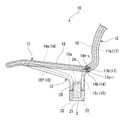
図2は、支持杆2に取り付けられた椅子本体10を示す図であり、図3は、支持杆2に取り付けられた椅子本体10の骨格部を示す図である。
椅子本体10は、着座者の臀部を支持する座11と、着座者の背部を支持する背凭れ12と、座11の左右の側縁部の下面から下方に延出して下端領域が支持杆2に固定される一対の連結脚13と、を備えている。
FIG. 2 is a view showing the
The
座11と連結脚13は、それぞれ骨格を成す金属製の座フレーム14と脚フレーム15を有している。脚フレーム15は、座フレーム14の左右両側の縁部に一体に結合されている。座フレーム14と左右の脚フレーム15,15とは、これらのほぼ全域が弾性を有する一体のモールド樹脂16によって被覆されている。モールド樹脂16としては、例えば、ウレタン等が用いられる。
The
モールド樹脂16は、一体に結合した座フレーム14と左右の脚フレーム15,15とを成形型内に設置し、その状態で溶融したウレタン等の樹脂を射出充填して形成される。モールド樹脂16は、この成形時に、表面に微細な凹凸(シボ模様)を有する加飾層を成形型内にセットして、モールド樹脂16の表面に加飾層を一体に形成することが望ましい。これにより、成形されたモールド樹脂16の外表面には、外観や手触りの良い微細な凹凸模様が形成されることになる。
The
背凭れ12は、骨格を成す金属製の背凭れフレーム17を有し、座11や連結脚13と同様に背凭れフレーム17の外側のほぼ全域がモールド樹脂16によって被覆されている。この背凭れ12のモールド樹脂16の外表面についても、座11や連結脚13と同様にして微細な凹凸模様を形成することが望ましい。
The
図3に示すように、座フレーム14は、座11の左右両側の側辺と前辺に沿う略コ字状のフレームロッド14aと、座11の後端部に配置されてフレームロッド14aの左右の後端部に溶接固定される平板状の接合プレート14bと、を有している。略コ字状のフレームロッド14aの内側には、S字状の屈曲部が複数連なる金属製のクッションバネ18が複数並列に張設されている。
As shown in FIG. 3, the
図4は、図3のIV−IV断面に対応する断面を示す図である。
接合プレート14bは、鉛直方向に対して上部が座11の前方側に向くように傾斜している。接合プレート14bの後部上方側を向く面は、背凭れフレーム17との当接面14b−uを構成している。当接面14b−uは、モールド樹脂16によって被覆されずに金属面として露出している。また、接合プレート14bは、図3に示すように、左右の両縁部が座11の下面の連結脚13の延出位置よりも幅方向外側に延出している。さらに、接合プレート14bは、幅方向の略中央位置が下方に最大に膨出するように、下縁部が略円弧状に湾曲して形成されている。
FIG. 4 is a view showing a cross section corresponding to the IV-IV cross section of FIG. 3.
The joining
また、脚フレーム15は、一端部側がフレームロッド14aの側辺の下面に溶接され、その一端部側から斜め後ろ下方に延出した後に他端部側が鉛直下方に屈曲する前部ロッド15fと、一端部側が接合プレート14bに接合され、その一端部側から斜め前下方に延出した後に他端部側が鉛直下方に屈曲する後部ロッド15rと、前部ロッド15fと後部ロッド15rの鉛直下方に延出する領域の中間部同士を接続する接続プレート15aと、を有している。ここで、前部ロッド15fと後部ロッド15rの鉛直下方に延出する領域をそれぞれ下方延出部15f−e,15r−eと呼ぶものとすると、図4に示すように、各下方延出部15f−e,15r−eの下面側には雌ねじの切られたボルト締結孔19が形成されている。
Further, the
図5は、座11を下面側から見た斜視図である。
脚フレーム15は、前部ロッド15fと後部ロッド15rの各下方延出部15f−e,15r−eの下面と、接続プレート15aの下面を除くほぼ全域がモールド樹脂16によって被覆されている。接続プレート15aの下面と、モールド樹脂16によって被覆された前後の下方延出部15f−e,15r−eの間には、下向きに略コ字状に開口する嵌合凹部20が形成されている。嵌合凹部20は、断面矩形状の支持杆2の略上半部に嵌合される。
FIG. 5 is a perspective view of the
The
断面矩形状の支持杆2の略下半部には、図2〜図4に示すように、上向きに開口する略コ字の受け金具21(受け部材)が嵌合され、受け金具21がその状態において連結脚13にボルト22によって締結固定されるようになっている。具体的には、受け金具21には、上下方向に貫通する一対のボルト挿通孔21a,21aが形成されており、受け金具21の下方からボルト挿通孔21a,21aにボルト22が挿入され、そのボルト22の先端部が連結脚13の対応するボルト締結孔19,19に締め込まれるようになっている。
受け金具21の前後の上端面は、ボルト22による締結時に連結脚13の下面が当接する座面21bとなる。座面21bには、脚フレーム15の下方延出部15f−e,15r−eの端面と、その下方延出部15f−e,15r−eの周域を覆うモールド樹脂16が当接する。
As shown in FIGS. 2 to 4, a substantially U-shaped receiving metal fitting 21 (receiving member) that opens upward is fitted into the substantially lower half of the
The upper and lower upper and lower surfaces of the
図3に示すように、背凭れフレーム17は、複数のロッド材が溶接されて形成されたロッド骨格体17aと、ロッド骨格体17aの下端に溶接された接合プレート17bと、を有している。ロッド骨格体17aの上部には、S字状の屈曲部が複数連なる金属製のクッションバネ23が張設されている。
接合プレート17bは、その下面が座フレーム14との当接面17b−lを構成し、座フレーム14側の当接面14b−uと当接するようになっている。当接面17b−uは、モールド樹脂16によって被覆されずに金属面として露出している。当接面17b−uは、座フレーム14側の当接面14b−uと略同形状に形成されている。
As shown in FIG. 3, the
The lower surface of the joining
図6は、図3のVI−VI断面に対応する断面を示す図である。
背凭れフレーム17と座フレーム14は、当接面17b−l,14b−uを相互に突き合わせた状態において、接合プレート17b,14b同士が複数のボルト24(締結部材)によって締結固定されている。接合プレート17b,14b同士のボルト24による締結箇所は、幅方向に離間した複数箇所に設けられている。ただし、接合プレート17b,14bの左右両側の各一つの締結箇所は、連結脚13の延出位置よりも幅方向外側位置に設けられている。また、接合プレート17b,14bを締結するボルト24の軸は、当接面17b−l,14b−uの傾斜と略直交する方向を指向している。
FIG. 6 is a view showing a cross section corresponding to the VI-VI cross section of FIG. 3.
The
また、座フレーム14の後縁部の下面を被覆するモールド樹脂16には、座11の裏面側に開口する締結作業孔25が形成されている。締結作業孔25は、接合プレート17b,14b同士を締結するボルト24を脱着するための作業孔であり、ボルト24による締結箇所に対応して、図5に示すように、モールド樹脂16上の複数箇所に設けられている。
Further, a
以上のように、この実施形態に係る椅子1は、椅子本体10の座フレーム14と脚フレーム15とが一体に結合され、座フレーム14と脚フレーム15とが弾性を有する一体のモールド樹脂16によって被覆されている。このため、この実施形態に係る椅子1においては、座11から連結脚13にかけての外観を形状的に連続させることができるとともに、質感も同じで不連続感のないものとすることができる。
As described above, in the
さらに、この実施形態に係る椅子1の場合、脚フレーム15の周囲のほぼ全域が、座11から連続するモールド樹脂16によってほぼ隙間なく覆われている。このため、連結脚13の脚フレーム15や、座フレーム14と脚フレーム15の連結部の周域をモールド樹脂16によって密に包み込み、連結脚13や、座11と連結脚13の連結部の剛性を効率良く高めることができる。また、脚フレーム15や、座フレーム14と脚フレーム15の連結部の周域がモールド樹脂16によって密に包み込まれることから、振動や異音の発生等をモールド樹脂16によって抑制することができる。
したがって、この実施形態に係る椅子1においては、低コストでの製造が可能な脚フレーム15を用いつつ、連結脚13の剛性低下と振動や異音の発生を抑制することができるため、連結脚全体を金属ブロックで形成する場合に比較して、機能面での不具合を招くことなく製造コストの低減を図ることができる。
Furthermore, in the case of the
Therefore, in the
また、この実施形態に係る椅子1では、連結脚13に嵌合凹部20が設けられ、接続プレート15aの金属面が嵌合凹部20の底部でモールド樹脂16に被覆されずに露出している。そして、連結脚13は、嵌合凹部20を支持杆2に嵌合した状態で嵌合凹部20と受け金具21で支持杆2を挟み込み、その状態で受け金具21が脚フレーム15にボルト締結されることで支持杆2に固定されている。このため、金属製の接続プレート15aが露出する嵌合凹部20の底部が支持杆2の上面に直接当接するようになる。したがって、この実施形態に係る椅子1においては、椅子本体10を支持杆2に対して正確にかつ安定的に位置決めすることができる。
Further, in the
さらに、この実施形態に係る椅子1の場合、脚フレーム15の下部領域は、受け金具21のボルト締結時に、受け金具21の座面21bに脚フレーム15とともに接触するようにモールド樹脂16が被覆されている。このため、この椅子1の場合、使用時に椅子本体10に偏った荷重が作用したとき等にモールド樹脂16が受け金具21の座面21bとの間で弾性変形し、それによって椅子本体10の支持杆2回りのガタツキや振動を抑制することができる。
Furthermore, in the case of the
また、この実施形態に係る椅子1においては、背凭れフレーム17が弾性を有するモールド樹脂16によって被覆され、背凭れフレーム17の下縁と座フレーム14の後縁には、モールド樹脂16によって被覆されずに相互に当接する当接面17b−l,14b−uが設けられている。そして、座フレーム14の後縁部の下面を被覆するモールド樹脂16には、座11の裏面側に開口する締結作業孔25が設けられ、背凭れフレーム17と座フレーム14とが、当接面17b−l,14b−uを突き合わせた状態で締結作業孔25を通して締結固定されている。このため、この実施形態に係る椅子1の場合、背凭れ12から座11、連結脚13にかけてを連続した外観とすることができるうえ、背凭れフレーム17と座フレーム14を締結するボルト24の頭部が締結作業孔25内に位置されることから、ボルト24の頭部が外部から見えにくく、外観をさらに良好なものとすることができる。
In the
また、この実施形態に係る椅子1の場合、背凭れフレーム17と座フレーム14の当接面17b−l,14b−uが、鉛直方向に対して、上部が座11の前方側を向くように傾斜し、背凭れフレーム17と座フレーム14を締結するボルト24の軸が当接面17b−l,14b−uの傾斜と略直交する方向を指向している。このため、着座者の背中から背凭れ12を後方に押す方向の力が作用したときに、ボルト24の軸にせん断方向の分力が作用しにくくなる。したがって、この構造を採用することにより、ボルト締結部の強度低下を抑制することができる。
In the case of the
さらに、この実施形態に係る椅子1においては、背凭れフレーム17と座フレーム14の当接面17b−l,14b−uの左右の縁部が、連結脚13の延出位置よりも幅方向外側に延出し、背凭れフレーム17と座フレーム14とが、連結脚13の延出位置よりも幅方向外側位置において各一カ所以上で相互にボルト締結されている。このため、椅子本体10への着座時に、座11と背凭れ17の間で応力の作用しにくい連結脚13の延出位置よりも幅方向外側部分で、当接面17b−l,14b−u同士が確実に締結状態を維持できるようになる。したがって、この構造を採用することにより、座11と背凭れ12の間に位置ずれが防止することができる。
Furthermore, in the
なお、この発明は上記の実施形態に限定されるものではなく、その要旨を逸脱しない範囲で種々の設計変更が可能である。例えば、上記の実施形態においては、直線上に延出する支持杆2に複数の椅子本体10…が横並びに設置されているが、図7に示す変形例の椅子101ように、水平方向で湾曲させた支持杆102に複数の椅子本体10…を取り付けるようにしても良い。
In addition, this invention is not limited to said embodiment, A various design change is possible in the range which does not deviate from the summary. For example, in the above-described embodiment, a plurality of chair
2 支持杆
10 単体椅子
11 座
12 背凭れ
13 連結脚
14 座フレーム
14b−u 当接面
15 脚フレーム
16 モールド樹脂
17 背凭れフレーム
17b−1 当接面
20 嵌合凹部
21 受け金具
21b 座面
24 ボルト(締結部材)
25 締結作業孔
2
25 Fastening hole
Claims (6)
略水平に延出し前記連結脚の下端領域が固定される支持杆と、を備えた椅子において、
前記座の骨格を成す座フレームと前記連結脚の骨格を成す脚フレームとが一体に結合され、
前記座フレームと前記脚フレームが、弾性を有する一体のモールド樹脂によって被覆されていることを特徴とする椅子。 A chair body having a seat for supporting a seated person's buttocks, and a connecting leg extending downward from the lower surface of the seat;
In a chair provided with a support rod that extends substantially horizontally and to which a lower end region of the connecting leg is fixed,
The seat frame forming the skeleton of the seat and the leg frame forming the skeleton of the connecting leg are integrally coupled,
The chair, wherein the seat frame and the leg frame are covered with an integral mold resin having elasticity.
前記嵌合凹部の少なくとも底部は、前記脚フレームが前記モールド樹脂によって被覆されずに露出し、
前記連結脚は、前記嵌合凹部を前記支持杆に嵌合した状態で当該嵌合凹部と受け部材で前記支持杆を挟み込み、前記受け部材が前記脚フレームに締結固定されることによって前記支持杆に固定されていることを特徴とする請求項1に記載の椅子。 The lower end region of the connecting leg is provided with a fitting recess to be fitted to the support rod,
At least the bottom of the fitting recess is exposed without the leg frame being covered with the mold resin,
The connecting leg sandwiches the support rod between the fitting recess and the receiving member in a state where the fitting recess is fitted to the support rod, and the receiving member is fastened and fixed to the leg frame. The chair according to claim 1, wherein the chair is fixed to the chair.
前記背凭れは、背凭れの骨格を成す背凭れフレームが、弾性を有するモールド樹脂によって被覆され、
前記背凭れフレームの下縁と前記座フレームの後縁には、前記モールド樹脂によって被覆されずに相互に当接する当接面が設けられ、
前記座フレームの後縁部の下面を被覆するモールド樹脂には、座の裏面側に開口する締結作業孔が設けられ、
前記背凭れフレームと前記座フレームとは、前記当接面を突き合わせた状態で、前記締結作業孔を通して締結固定されていることを特徴とする請求項1〜3のいずれか1項に記載の椅子。 The chair body further includes a backrest that supports the back of the seated person,
In the backrest, the backrest frame forming the backbone of the backrest is covered with an elastic mold resin,
The lower edge of the backrest frame and the rear edge of the seat frame are provided with contact surfaces that contact each other without being covered with the mold resin,
The mold resin that covers the lower surface of the rear edge portion of the seat frame is provided with a fastening work hole that opens on the back side of the seat,
The chair according to any one of claims 1 to 3, wherein the backrest frame and the seat frame are fastened and fixed through the fastening work hole in a state where the contact surfaces are abutted with each other. .
前記背凭れフレームと前記座フレームを締結固定する締結部材の軸は前記当接面の傾斜と略直交する方向を指向していることを特徴とする請求項4に記載の椅子。 The contact surface is inclined with respect to the vertical direction so that the upper part faces the front side of the seat,
The chair according to claim 4, wherein an axis of a fastening member that fastens and fixes the backrest frame and the seat frame is oriented in a direction substantially orthogonal to the inclination of the contact surface.
前記背凭れフレームと前記座フレームとは、少なくとも前記連結脚の延出位置よりも幅方向外側位置において相互に締結固定されていることを特徴とする請求項4または5に記載の椅子。 At least a part of the contact surface between the backrest frame and the seat frame extends outward in the width direction from the extending position of the connecting leg,
The chair according to claim 4 or 5, wherein the backrest frame and the seat frame are fastened and fixed to each other at least at a position on the outer side in the width direction from the extended position of the connecting leg.
Priority Applications (4)
| Application Number | Priority Date | Filing Date | Title |
|---|---|---|---|
| JP2014213598A JP6433055B2 (en) | 2014-10-20 | 2014-10-20 | Chair |
| PCT/JP2015/079415 WO2016063826A1 (en) | 2014-10-20 | 2015-10-19 | Chair |
| GB1706099.7A GB2546045B (en) | 2014-10-20 | 2015-10-19 | Chair |
| CN201580056881.1A CN107072399A (en) | 2014-10-20 | 2015-10-19 | Chair |
Applications Claiming Priority (1)
| Application Number | Priority Date | Filing Date | Title |
|---|---|---|---|
| JP2014213598A JP6433055B2 (en) | 2014-10-20 | 2014-10-20 | Chair |
Publications (2)
| Publication Number | Publication Date |
|---|---|
| JP2016077668A JP2016077668A (en) | 2016-05-16 |
| JP6433055B2 true JP6433055B2 (en) | 2018-12-05 |
Family
ID=55760862
Family Applications (1)
| Application Number | Title | Priority Date | Filing Date |
|---|---|---|---|
| JP2014213598A Active JP6433055B2 (en) | 2014-10-20 | 2014-10-20 | Chair |
Country Status (4)
| Country | Link |
|---|---|
| JP (1) | JP6433055B2 (en) |
| CN (1) | CN107072399A (en) |
| GB (1) | GB2546045B (en) |
| WO (1) | WO2016063826A1 (en) |
Family Cites Families (11)
| Publication number | Priority date | Publication date | Assignee | Title |
|---|---|---|---|---|
| CN2039938U (en) * | 1988-10-22 | 1989-06-28 | 刘世明 | Integrated sofa and bed head made of frame and plastic-foam |
| CN2270418Y (en) * | 1996-08-26 | 1997-12-17 | 韩进忠 | Sofa with once forming frame structure |
| JP2008061783A (en) * | 2006-09-06 | 2008-03-21 | Itoki Corp | Support device of lobby chair |
| JP5259993B2 (en) * | 2007-07-09 | 2013-08-07 | 株式会社岡村製作所 | Chair |
| JP5259995B2 (en) * | 2007-07-09 | 2013-08-07 | 株式会社岡村製作所 | Chair |
| JP5378870B2 (en) * | 2009-04-28 | 2013-12-25 | 株式会社岡村製作所 | Connection structure between seat and backrest |
| CN201499866U (en) * | 2009-08-21 | 2010-06-09 | 典立塑胶股份有限公司 | Rest chair |
| CN102273841B (en) * | 2010-06-09 | 2013-09-11 | 亲亲贸易有限公司 | Seat and molding method thereof |
| CN102525173B (en) * | 2010-12-31 | 2014-10-29 | 厦门大端工业设计有限公司 | Sofa with built-in frames |
| CN202264672U (en) * | 2011-08-22 | 2012-06-06 | 上海龙洲塑料模具有限公司 | Double-injection molding automobile interior decoration seat back plate structure |
| JP6355883B2 (en) * | 2012-10-10 | 2018-07-11 | 株式会社オカムラ | Chair |
-
2014
- 2014-10-20 JP JP2014213598A patent/JP6433055B2/en active Active
-
2015
- 2015-10-19 GB GB1706099.7A patent/GB2546045B/en not_active Expired - Fee Related
- 2015-10-19 CN CN201580056881.1A patent/CN107072399A/en active Pending
- 2015-10-19 WO PCT/JP2015/079415 patent/WO2016063826A1/en active Application Filing
Also Published As
| Publication number | Publication date |
|---|---|
| CN107072399A (en) | 2017-08-18 |
| GB2546045B (en) | 2020-07-15 |
| JP2016077668A (en) | 2016-05-16 |
| GB201706099D0 (en) | 2017-05-31 |
| GB2546045A (en) | 2017-07-05 |
| WO2016063826A1 (en) | 2016-04-28 |
Similar Documents
| Publication | Publication Date | Title |
|---|---|---|
| WO2018154828A1 (en) | Seat | |
| WO2017213229A1 (en) | Load support structure for chair, load support body for chair, and chair | |
| JP6433055B2 (en) | Chair | |
| JP2018001900A (en) | Vehicle seat | |
| JP6495358B2 (en) | Vehicle seat | |
| JP6355883B2 (en) | Chair | |
| JP2019076590A (en) | table | |
| JP6343801B2 (en) | Chair face material mounting structure, chair body support member and chair | |
| JP4383788B2 (en) | Chair | |
| JP6898571B2 (en) | Vehicle seat | |
| JP6188541B2 (en) | Chair | |
| JP5767010B2 (en) | Chair | |
| JP4951776B2 (en) | Chair | |
| JP6355238B2 (en) | Chair | |
| JP6920622B2 (en) | Vehicle seat | |
| JP4238083B2 (en) | Chair seat shell structure | |
| CN111845491B (en) | Chair backrest | |
| JP5461877B2 (en) | Chair backrest structure | |
| JP4238082B2 (en) | Chair | |
| JP2021181302A (en) | Vehicle seat | |
| JP6513726B2 (en) | Vehicle seat | |
| JP2017217375A (en) | Load bearing structure for chair and chair | |
| JP6226700B2 (en) | Chair | |
| JP2022073407A (en) | Chair structure and chair | |
| JP6758933B2 (en) | Load support for chairs and chairs |
Legal Events
| Date | Code | Title | Description |
|---|---|---|---|
| A621 | Written request for application examination |
Free format text: JAPANESE INTERMEDIATE CODE: A621 Effective date: 20171004 |
|
| TRDD | Decision of grant or rejection written | ||
| A01 | Written decision to grant a patent or to grant a registration (utility model) |
Free format text: JAPANESE INTERMEDIATE CODE: A01 Effective date: 20181009 |
|
| A61 | First payment of annual fees (during grant procedure) |
Free format text: JAPANESE INTERMEDIATE CODE: A61 Effective date: 20181105 |
|
| R150 | Certificate of patent or registration of utility model |
Ref document number: 6433055 Country of ref document: JP Free format text: JAPANESE INTERMEDIATE CODE: R150 |
|
| R250 | Receipt of annual fees |
Free format text: JAPANESE INTERMEDIATE CODE: R250 |
|
| R250 | Receipt of annual fees |
Free format text: JAPANESE INTERMEDIATE CODE: R250 |
|
| R250 | Receipt of annual fees |
Free format text: JAPANESE INTERMEDIATE CODE: R250 |