WO2023054208A1 - 乗り物用シート - Google Patents
乗り物用シート Download PDFInfo
- Publication number
- WO2023054208A1 WO2023054208A1 PCT/JP2022/035530 JP2022035530W WO2023054208A1 WO 2023054208 A1 WO2023054208 A1 WO 2023054208A1 JP 2022035530 W JP2022035530 W JP 2022035530W WO 2023054208 A1 WO2023054208 A1 WO 2023054208A1
- Authority
- WO
- WIPO (PCT)
- Prior art keywords
- lock
- seat
- lever
- cover
- fitting portion
- Prior art date
Links
- 239000000463 material Substances 0.000 claims description 31
- 230000003014 reinforcing effect Effects 0.000 claims description 22
- 230000002093 peripheral effect Effects 0.000 claims description 7
- 230000005540 biological transmission Effects 0.000 description 46
- 238000005452 bending Methods 0.000 description 14
- 238000012986 modification Methods 0.000 description 12
- 230000004048 modification Effects 0.000 description 12
- 210000000078 claw Anatomy 0.000 description 8
- 238000010586 diagram Methods 0.000 description 5
- 239000011347 resin Substances 0.000 description 5
- 229920005989 resin Polymers 0.000 description 5
- 238000003780 insertion Methods 0.000 description 4
- 230000037431 insertion Effects 0.000 description 4
- 239000002184 metal Substances 0.000 description 4
- 230000002787 reinforcement Effects 0.000 description 4
- 230000000149 penetrating effect Effects 0.000 description 2
- 239000011162 core material Substances 0.000 description 1
- 238000007790 scraping Methods 0.000 description 1
- 230000037303 wrinkles Effects 0.000 description 1
Images


Classifications
-
- B—PERFORMING OPERATIONS; TRANSPORTING
- B60—VEHICLES IN GENERAL
- B60N—SEATS SPECIALLY ADAPTED FOR VEHICLES; VEHICLE PASSENGER ACCOMMODATION NOT OTHERWISE PROVIDED FOR
- B60N2/00—Seats specially adapted for vehicles; Arrangement or mounting of seats in vehicles
- B60N2/90—Details or parts not otherwise provided for
-
- B—PERFORMING OPERATIONS; TRANSPORTING
- B60—VEHICLES IN GENERAL
- B60N—SEATS SPECIALLY ADAPTED FOR VEHICLES; VEHICLE PASSENGER ACCOMMODATION NOT OTHERWISE PROVIDED FOR
- B60N2/00—Seats specially adapted for vehicles; Arrangement or mounting of seats in vehicles
- B60N2/005—Arrangement or mounting of seats in vehicles, e.g. dismountable auxiliary seats
- B60N2/015—Attaching seats directly to vehicle chassis
- B60N2/01508—Attaching seats directly to vehicle chassis using quick release attachments
- B60N2/01516—Attaching seats directly to vehicle chassis using quick release attachments with locking mechanisms
- B60N2/01583—Attaching seats directly to vehicle chassis using quick release attachments with locking mechanisms locking on transversal elements on the vehicle floor or rail, e.g. transversal rods
-
- B—PERFORMING OPERATIONS; TRANSPORTING
- B60—VEHICLES IN GENERAL
- B60N—SEATS SPECIALLY ADAPTED FOR VEHICLES; VEHICLE PASSENGER ACCOMMODATION NOT OTHERWISE PROVIDED FOR
- B60N2/00—Seats specially adapted for vehicles; Arrangement or mounting of seats in vehicles
- B60N2/24—Seats specially adapted for vehicles; Arrangement or mounting of seats in vehicles for particular purposes or particular vehicles
- B60N2/30—Non-dismountable or dismountable seats storable in a non-use position, e.g. foldable spare seats
- B60N2/3002—Non-dismountable or dismountable seats storable in a non-use position, e.g. foldable spare seats back-rest movements
- B60N2/3004—Non-dismountable or dismountable seats storable in a non-use position, e.g. foldable spare seats back-rest movements by rotation only
- B60N2/3009—Non-dismountable or dismountable seats storable in a non-use position, e.g. foldable spare seats back-rest movements by rotation only about transversal axis
- B60N2/3011—Non-dismountable or dismountable seats storable in a non-use position, e.g. foldable spare seats back-rest movements by rotation only about transversal axis the back-rest being hinged on the cushion, e.g. "portefeuille movement"
-
- B—PERFORMING OPERATIONS; TRANSPORTING
- B60—VEHICLES IN GENERAL
- B60N—SEATS SPECIALLY ADAPTED FOR VEHICLES; VEHICLE PASSENGER ACCOMMODATION NOT OTHERWISE PROVIDED FOR
- B60N2/00—Seats specially adapted for vehicles; Arrangement or mounting of seats in vehicles
- B60N2/24—Seats specially adapted for vehicles; Arrangement or mounting of seats in vehicles for particular purposes or particular vehicles
- B60N2/30—Non-dismountable or dismountable seats storable in a non-use position, e.g. foldable spare seats
- B60N2/3038—Cushion movements
- B60N2/304—Cushion movements by rotation only
- B60N2/3045—Cushion movements by rotation only about transversal axis
- B60N2/305—Cushion movements by rotation only about transversal axis the cushion being hinged on the vehicle frame
-
- B—PERFORMING OPERATIONS; TRANSPORTING
- B60—VEHICLES IN GENERAL
- B60N—SEATS SPECIALLY ADAPTED FOR VEHICLES; VEHICLE PASSENGER ACCOMMODATION NOT OTHERWISE PROVIDED FOR
- B60N2/00—Seats specially adapted for vehicles; Arrangement or mounting of seats in vehicles
- B60N2/24—Seats specially adapted for vehicles; Arrangement or mounting of seats in vehicles for particular purposes or particular vehicles
- B60N2/32—Seats specially adapted for vehicles; Arrangement or mounting of seats in vehicles for particular purposes or particular vehicles convertible for other use
- B60N2/36—Seats specially adapted for vehicles; Arrangement or mounting of seats in vehicles for particular purposes or particular vehicles convertible for other use into a loading platform
- B60N2/366—Seats specially adapted for vehicles; Arrangement or mounting of seats in vehicles for particular purposes or particular vehicles convertible for other use into a loading platform characterised by the locking device
-
- B—PERFORMING OPERATIONS; TRANSPORTING
- B60—VEHICLES IN GENERAL
- B60N—SEATS SPECIALLY ADAPTED FOR VEHICLES; VEHICLE PASSENGER ACCOMMODATION NOT OTHERWISE PROVIDED FOR
- B60N2/00—Seats specially adapted for vehicles; Arrangement or mounting of seats in vehicles
- B60N2/58—Seat coverings
- B60N2/60—Removable protective coverings
- B60N2/6009—Removable protective coverings covering more than only the seat
Definitions
- the present invention relates to a vehicle seat, and more particularly to a vehicle seat capable of switching a seat body having a seat back and a seat cushion from a normal state.
- a vehicle seat in which a seat body can be switched between a "normal state” and a “moving state” in which the seat body is moved from the normal state.
- the “moving state” includes, for example, a “storage state” in which the seat body is stored and moved to the vehicle body floor side, a “sliding state” in which the seat body is slid from the normal state to a predetermined position in the seat front-rear direction, and a “slide movement state”.
- a "reclining state” in which the (seat back) is tilted backward from a normal state to a predetermined position, and the like can be mentioned.
- the vehicle seat includes a lock device (lock member) that locks the movement of the seat body in the "normal state” and an operation lever that is operated to release the locked state of the lock device.
- a vehicle seat provided with such an arrangement (see, for example, Patent Document 1).
- the vehicle seat described in Patent Document 1 is a seat whose seat body can be switched between a "normal state” and a “storage state.”
- the vehicle seat includes a lock device (lock member), a lock cover that covers the lock device, a lever attachment member that is attached to the vehicle seat, and a lever attachment member that is attached to unlock the lock device. and an operable operating lever.
- the lock cover and the lever mounting member are assembled by a plurality of fitting portions in the seat width direction, and these fitting portions extend in the same direction when viewed from the side of the seat.
- the present invention has been made in view of the above problems, and an object of the present invention is to provide a vehicle seat in which the components of the device for switching the state of the seat body can be more firmly assembled in a well-balanced manner than before. to do. Another object of the present invention is to provide a vehicle seat in which the assembly structure of the components in the device for switching the state of the seat body is simplified.
- the seat body has a seat back and a seat cushion, and the seat body is switchable between a normal state and a moving state in which the seat body is moved from the normal state.
- a vehicle seat comprising: a lock device for locking movement of the seat body in the normal state; a lock cover covering the lock device; a lever attachment member attached to the vehicle seat; an operation lever attached to a member and operated to release the locked state of the lock device, wherein the lever attachment member is a first engagement member that is engaged with a first engagement portion provided on the lock cover; A fitting portion and a second fitting portion that fits into a second fitted portion provided on the lock cover, wherein the first fitting portion and the second fitting portion It extends in a direction orthogonal to the fitting direction of the lock cover and extends in directions crossing each other.
- the lever mounting member is fitted to the lock cover by a plurality of fitting portions, and the first fitting portion and the second fitting portion each extend in a direction orthogonal to the fitting direction of the lock cover. and extend in directions that intersect each other. Since the first fitting portion and the second fitting portion extend in different directions in this way, even when loads are applied from various directions, for example, the fitting structure is stronger than the conventional structure. can do.
- the moving state is a stowed state in which the seat back is stowed and moved toward the floor of the vehicle body, and the locking device is detachably engaged with a striker provided on the vehicle body or the vehicle seat. and a locking member that moves between a locking position for locking the storage operation of the seatback and an unlocking position, wherein the first fitting portion and the second fitting portion extend in directions perpendicular to each other.
- the lock cover is assembled to the lever mounting member in the seat width direction, the first fitting portion and the second fitting portion are arranged at different positions in the vertical direction, and It is good if they are placed in different positions.
- a connecting member is provided which connects the locking device and the operating lever and acts to switch the locking device from the locked state to the unlocked state in response to the operation of the operating lever, and the lever attachment member
- the lock cover further includes a third fitting portion that fits into a third fitted portion provided on the lock cover, and the third fitting portion is attached to the first fitting portion and the second fitting portion with respect to the connecting member. It is preferable that it is arranged on the side opposite to the fitting portion side.
- the first fitting portion and the third fitting portion are elongated in the same direction.
- the lock cover is assembled to the lever mounting member in the seat width direction, and the second fitting portion is arranged between the first fitting portion and the third fitting portion in the seat front-rear direction. It's good to be With the above configuration, the lever mounting member and the lock cover can be firmly assembled in a well-balanced manner.
- the lock cover has a first lock cover that covers the lock device, and a second lock cover that is attached to a side surface of the first lock cover, and the first fitted portion and the third lock cover.
- the fitted portion may be formed in the first lock cover, and the second fitted portion may be formed in the second lock cover. Since the lever mounting member, the first lock cover, and the second lock cover are fitted to each other by the plurality of fitting portions as described above, these components can be assembled stably and firmly.
- the lever mounting member and the lock cover are assembled by fitting the first fitting portion, the second fitting portion, and the third fitting portion in the same direction.
- the above configuration facilitates the operation of assembling the lock cover to the lever mounting member. In addition, it becomes easy to automate the assembly work.
- the lock cover has a cover flange formed so as to protrude from the side surface of the outer edge portion of the lock cover toward the lock device and arranged to surround the lock device.
- the joint portion, the second fitting portion, and the third fitting portion may be arranged outside the cover flange on the side surface of the lock cover.
- the lock cover is formed so as to protrude from the side surface of the outer edge portion of the lock cover toward the lock device, and includes a first reinforcing portion that connects the cover flange and the first fitting portion, and the lock. It is preferable to have a second reinforcing portion formed so as to protrude from the side surface of the outer edge portion of the cover toward the locking device and connect the cover flange and the third fitting portion.
- a connecting member that connects the locking device and the operating lever and acts to switch the locking device from the locked state to the unlocked state in response to the operation of the operating lever, and attached to the connecting member, a position holding member that holds the position of the connecting member, the connecting member extending between the lock device and the operating lever, and the position holding member extending in the extending direction of the connecting member. and attached to the connecting member along the connecting member.
- the moving state is a stowed state in which the seat back is stowed and moved toward the floor of the vehicle body, and the locking device is detachably engaged with a striker provided on the vehicle body or the vehicle seat. and a lock member that moves between a lock position for locking the storage operation of the seat back and an unlock position, wherein the position holding member has flexibility and extends in the extending direction of the position holding member. It is preferable that the position of the connecting member is held by bending in a direction perpendicular to .
- a connecting member that connects the locking device and the operating lever and acts to switch the locking device from the locked state to the unlocked state in response to the operation of the operating lever, and is assembled to the connecting member, a biasing member that biases the connecting member toward the locking device side or the operating lever side, the connecting member having an assembly portion for mounting the biasing member, and a body portion of the connecting member. and the assembly portion are preferably formed integrally.
- the moving state is a stowed state in which the seat back is stowed and moved toward the floor of the vehicle body, and the locking device is detachably engaged with a striker provided on the vehicle body or the vehicle seat. and a lock member that moves between a lock position for locking the storage operation of the seat back and an unlock position, wherein the assembly portion extends from the side surface of the main body portion of the connection member toward the biasing member. preferably an assembly projection projecting from the bottom and assembled to one end of the biasing member.
- a cover member is arranged between the lever mounting member and the operating lever and covers the operating lever, and a cover member is provided between the lever mounting member and the cover member and is arranged so as to surround the operating lever.
- a plate-like plate member wherein the operation lever is provided so as to be exposed from a skin opening hole formed in an outer surface of a skin material serving as a covering material for the seat body, and the skin material has the skin opening hole. is sandwiched between the cover member and the plate member, and the lever mounting member protrudes from the main body portion of the lever mounting member toward the plate member side and contacts the side surface of the plate member. to support the plate member.
- the lever mounting member has a plate supporting portion that protrudes from the main body portion of the lever mounting member toward the plate member side and supports the plate member by contacting the side surface of the plate member. Therefore, when assembling the plate member to the lever mounting member, there is no need to perform separate processing on the plate member side. That is, it is possible to simplify the assembly structure compared to the conventional art.
- each component of the device for switching the state of the seat body can be firmly assembled in a well-balanced manner.
- the assembly structure of the components of the device can be simplified.
- each component in a vehicle seat capable of storing the seat body, each component can be firmly assembled in a well-balanced manner.
- the lever mounting member and the lock cover can be assembled firmly with good balance. Also, these components can be stably assembled.
- the operation of assembling the lock cover to the lever mounting member is facilitated. In addition, it becomes easy to automate the assembly work. Further, according to the present invention, the fitting strength of the lock cover can be increased.
- each component can be compactly arranged in the vehicle seat that can accommodate the seat body.
- the locking device has a simple structure.
- the assembly structure of the components of the device can be simplified.
- each component can be compactly arranged in the vehicle seat that can accommodate the seat body.
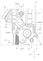
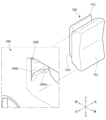
- FIG. 1 is a perspective view of a vehicle seat according to a first embodiment
- FIG. It is a perspective view of a seat frame.
- 3 is a perspective view of an operating lever, a cover member, a plate member, a lever attachment member, a lock member and a lock cover
- FIG. FIG. 4 is a perspective view when FIG. 3 is viewed from another angle
- FIG. 4 is an exploded perspective view of FIG. 3 (No. 1);
- FIG. 4 is an exploded perspective view of FIG. 3 (No. 2); It is a figure which shows the assembly
- FIG. 4 is a perspective view of a connecting link and a position holding member; FIG. It is a side view of a connecting link and a position holding member.
- FIG. 4 is a perspective view of a lever mounting member, a connecting link, and a position holding member, showing a state where the position holding member is in contact with the lever mounting member;
- FIG. 4 is a perspective view of a connecting link, a locking member, and a biasing spring, showing an assembled state of the connecting link;
- FIG. 10 is a diagram showing a state in which the lever mounting member and the lock cover are fitted; It is a figure which shows the fitting part of a lock cover and a 2nd lock cover.
- FIG. 10 is a diagram showing a state in which the operating lever and lock member are in the "locked position”;
- FIG. 10 is a diagram showing a state in which the operating lever and lock member are in the "intermediate position”;
- FIG. 10 is a diagram showing a state in which the operating lever and the lock member are in the "unlocked position”; It is a side view of the cover member of a modification, and a lever attachment member.
- FIG. 10 is a perspective view of a vehicle seat according to a second embodiment; 1 is a perspective view of a switching device; FIG. FIG.
- FIG. 23 is a perspective view when FIG. 22 is viewed from another angle;
- FIG. 4 is a side view of the switching device, showing a state in which a cushioning member is attached to the lock device (lock cover); 3 is an exploded perspective view of a cushioning member and a lock cover (first lock cover); FIG. It is an assembly drawing of a buffer member and a lock cover. It is a perspective view of a cushioning member.
- FIG. 27 is a cross-sectional view taken along line XXVIII-XXVIII of FIG. 26;
- FIG. 10 is a diagram showing a state in which the cushioning member of Modification 1 is attached to the lock cover; 4 is an exploded perspective view of a cushioning member and a lock cover; FIG.
- FIG. 11 is an exploded perspective view of a buffer member and a lock cover of Modification 2; It is a perspective view of a cushioning member.
- FIG. 11 is an exploded perspective view of a buffer member and a lock cover of Modified Example 3; It is a perspective view of a cushioning member.
- FIG. 11 is an exploded perspective view of a buffer member and a lock cover of Modification 4; It is a perspective view of a cushioning member.
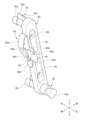
- FIG. This embodiment is a vehicle seat that can switch the seat body between a "normal state” and a "moving state", and includes a locking member that locks the movement of the seat body and a lock member that unlocks the locking member. a connecting link that connects the lock member and the operating lever and acts to unlock the locking member in response to the operation of the operating lever; and a connecting link that is attached to the connecting link to change the position of the connecting link. and a position holding member for holding the position holding member, wherein the position holding member extends in the extending direction of the connecting link and is attached to the connecting link along the connecting link. It relates to a sheet for Note that the side of the seat back of the vehicle seat on which the passenger sits is the front side of the seat.
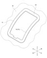
- the vehicle seat S of this embodiment is, as shown in FIG. 1, a rear seat corresponding to, for example, a rear seat of a vehicle. It can also be used as a second row middle seat in a vehicle having three rows of seats in the longitudinal direction of the vehicle.
- the vehicle seat S is a seat that can be arranged in two types, a "normal state” in which a occupant can be seated, and a "storage state” in which the seat body is stored on the floor side of the vehicle body. Specifically, when the vehicle seat S is in the "normal state”, when the occupant operates the operation lever 50 shown in FIG. switch to the "storage state". In addition, when the seat body is in the "storage state", the occupant manually raises the seat body to return to the "normal state”.
- the vehicle seat S is mounted between a seat body having a seat back 1, a seat cushion 2, and a headrest 3, a seat cushion 2, and a vehicle floor.
- a support leg 30 for supporting the seat back 1 a support base 35 for rotatably supporting the seat back 1, and a support base 35 attached to the outer surface of the seat back 1 in the seat width direction to move the seat body from the "normal state” to the "storage state”.
- a switching device 40 for switching.
- the seat back 1 is a backrest portion that supports the back of the occupant from behind. Constructed by covering.
- An operation lever 50 is attached to the left side portion of the upper surface of the seat back 1 in the seat width direction.
- the seat cushion 2 is a seating portion that supports an occupant from below, and is constructed by placing a pad material 2a on a cushion frame 20 shown in FIG.
- the headrest 3 is a head portion that supports the occupant's head from behind, and is constructed by placing a pad material on a pillar (not shown) serving as a core material and covering it with a skin material.
- the back frame 10 is composed of a rectangular frame-like body, and includes a frame-like main frame 11 made of a pipe material and a plate-like panel frame 12 attached to the rear of the seat of the main frame 11. , a vertically extending connecting frame 13 mounted in the frame of the main frame 11, and an elastic support member 14 extending in the seat width direction for supporting a seated person.
- Left and right vehicle body connection brackets 15 for connecting with the support base 35 are attached to the outer surface of the lower portion of the main frame 11 .
- the vehicle body connection bracket 15 is made of a sheet metal member that extends in the vertical direction. It is mounted so that it can be rotated by The vehicle body connection bracket 15 is sandwiched between the back frame 10 and the cushion frame 20 in the seat width direction.
- a seat rotation shaft 16 pivotally supported by a support base 35 in the seat width direction is provided at the lower portion of the left vehicle body connection bracket 15 , and a seat rotation shaft 16 is provided at the lower end of the right vehicle body connection bracket 15 relative to the support base 35 .
- a reclining device 17 that rotatably connects the back frame 10 is attached.
- the reclining device 17 is attached to the outer surface of the right vehicle body connection bracket 15 in the seat width direction.
- the reclining device 17 includes a spiral spring (not shown) that rotates the back frame 10 forward about the seat rotation shaft 16 to urge the seat in the retracted state.
- This spiral spring is configured such that one end thereof is locked to the back frame 10 side and the other end is locked to the support base 35 side.
- the reclining device 17 is actuated by releasing the locked state of the seat back 1 by operating the operation lever 50, and rotates the back frame 10 forward by the biasing force of the spiral spring to fold it toward the floor of the vehicle body. be able to.
- the cushion frame 20 is formed of a rectangular frame, and includes left and right side frames 21 arranged on the left and right sides, and a front connecting frame 22 connecting the front portions of the side frames 21 . , and a pan frame 24 as a plate-like frame connecting the front connecting frame 22 and the central connecting frame 23. .
- the side frame 21 is made of a sheet metal member having a U-shaped cross section extending in the seat front-rear direction. installed.
- a cushion rotating device 25 is attached to the rear end portion of the left side frame 21 to connect the cushion frame 20 to the back frame 10 so as to be rotatable about a cushion rotating shaft 26 .
- the front connection frame 22 is a U-shaped pipe member, and the support leg 30 is rotatably connected to the cushion frame 20 about the leg rotation shaft 28 on the inner surface in the seat width direction.
- a leg rotating device 27 is attached.
- the support leg 30 is a U-shaped pipe member that supports the seat cushion 2 from below. and a leg connecting portion 32 that connects the lower end portion.
- the upper end portion of the leg body portion 31 is connected to the inner surface of the central portion of the cushion frame 20 in the front-rear direction.
- a central portion of the leg connecting portion 32 in the seat width direction is detachably held by a leg holding member (not shown) on the floor of the vehicle body.
- the upper end of the support leg 30 projects further toward the front of the seat than the lower end of the support leg 30, and is inclined upward forward from the lower end of the support leg 30 toward the upper end thereof.
- the support base 35 is a member that supports the seat back 1 from below, and is made of an L-shaped sheet metal member elongated in the seat front-rear direction.
- the support base 35 is arranged laterally in the seat width direction and connected to the vehicle body floor.
- the support base 35 includes a connecting wall portion 36 connected to the upper surface of the vehicle body floor, and an upwardly bending and extending portion extending from the inner end portion of the connecting wall portion 36 . and an outer wall portion 37 connected via the driving shaft 16 .
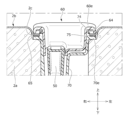
- the switching device 40 is a device for switching the vehicle seat S from the "normal state” to the “storage state", and is mounted on the upper portion of the seat back 1 (back frame 10). installed.
- the occupant operates the operating lever 50 from the "normal state (usage state)" of the vehicle seat S
- the locked state of the seat back 1 by the switching device 40 is released.
- the reclining device 17 shown in FIG. 2 operates, and specifically, the seatback 1 can be folded forward by rotating it forward by the biasing force of a spiral spring (not shown).
- the cushion rotation device 25 and leg rotation device 27 shown in FIG. It can be folded by rotating toward the seat cushion 2 around the rotating shaft 28 .
- the seat body is stored in the vehicle body floor, and the vehicle seat S is switched from the "normal state” to the "storage state".
- the vehicle seat S is to be returned from the "storage state” to the "normal state"
- the occupant lifts the seat body by hand against the urging force of a spiral spring (not shown), thereby disengaging the switching device 40.
- the locking member 91 is engaged with the striker 41 to switch the seat back 1 to the locked state.
- the striker 41 is a part of the vehicle body member and fixed to the vehicle body.
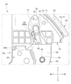
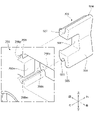
- the switching device 40 includes a lock device 90 that locks the movement of the seat body in the "normal state” and an operation lever that operates to release the locked state of the lock device 90.
- a connecting link 80 that connects the locking device 90 and the operating lever 50 and acts to unlock the locking device 90 in response to the operation of the operating lever 50; and a position holding member 89 that holds the position.
- the operating lever 50 is housed in a cover member 60 and a lever mounting member 70 provided on the upper surface of the seat back 1 . It is rotatably attached to the lever attachment member 70 via the lever rotation shaft 51 .
- the lock device 90 is covered with lock covers 98 and 99 and stored in the lock covers 98 and 99 .
- the operating lever 50 is a lever that is rotated to release the locked state of the locking device 90, and is attached to the side portion of the seatback 1.
- the operating lever 50 is housed in a cover member 60 and a lever mounting member 70 provided on the outer surface of the seat back 1 . It is rotatably attached to the lever attachment member 70 via the lever rotation shaft 51 .
- the operation lever 50 is a lever elongated in the seat front-rear direction, the front end portion of which corresponds to the "base end portion", and the rear end portion of which corresponds to the "tip end portion".
- the operating lever 50 is rotatable between a "normal position (locked position)" shown in FIGS. 3 and 17 and a “rotating position (unlocked position)” shown in FIG. 19 rotated from the normal position. It is installed so that The operating lever 50 is urged from the rotating position side to the normal position side by a connecting link 80 interposed between the operating lever 50 and the lock device 90 .
- the operating lever 50 has an upper wall portion 50a that forms the outer surface of the operating lever 50 and extends while curving in the seat front-rear direction.
- left and right second side wall portions 50d further extending downward from 50c; and a bottom wall portion 50e connecting the left and right second side wall portions 50d and projecting from the left and right second side wall portions 50d toward the rear of the seat.
- a reinforcing wall portion 50f connecting the left and right second side wall portions 50d and the bottom wall portion 50e.
- the operation lever 50 is formed on left and right side wall portions 50c and has left and right lever rotation shafts 51 projecting outward in the seat width direction from the respective side wall portions 50c. As shown in FIGS. 5, 6, and 10, the left and right lever rotating shafts 51 pass through the cover member 60 and are pivotally supported by shaft support portions 71 formed on the left and right sides of the lever mounting member 70. there is
- the operation lever 50 is formed by a rear end portion of the upper wall portion 50a and rear end portions of the left and right side wall portions 50c, and has a lever operation portion 52 for hooking the finger of the passenger.
- the lever operating portion 52 is formed so as to be substantially flush with the upper surface of the cover member 60 .
- the operating lever 50 also has a lever restricting portion 53 that is formed at the front end portion of the upper wall portion 50 a and restricts the pivotal movement of the operating lever 50 .
- the lever restricting portion 53 is arranged so as to be able to contact a lever contact portion 63 formed at the front end portion of the cover member 60 , and restricts the operation of the operating lever 50 by contacting the lever contact portion 63 .
- the operation lever 50 has left and right engaging portions 54 (link engaging portions) that are formed on the left and right second side wall portions 50d and protrude outward in the seat width direction from the respective second side wall portions 50d. . 5, 6, and 10, the left and right engaging portions 54 pass through the cover member 60, face the opening 73 of the lever mounting member 70, and engage the lever engaging portion 82 of the connecting link 80. concatenated. Specifically, the left and right engaging portions 54 are engaging holes having concave shapes and are connected to convex lever engaging portions 82 (lever engaging convex portions).
- the cover member 60 is a cover plate that supports the operating lever 50, and is attached to the lever attachment member 70 while being housed inside the lever attachment member 70. As shown in FIG. Specifically, the cover member 60 and the lever mounting member 70 sandwich a portion of the skin material 1b (peripheral portion of the opening formed in the skin material 1b). By doing so, the external appearance around the operation lever 50 is improved.
- the cover member 60 has a box shape with an open bottom. More specifically, the cover member 60 includes left and right side wall portions 60a arranged at a predetermined interval in the seat width direction, a front wall portion 60b connecting front ends of the left and right side wall portions 60a, and left and right side wall portions 60b. It has a rear wall portion 60c that connects the rear end portions of 60a, and a bottom wall portion 60d that connects the lower end portions of the left and right side wall portions 60a and the rear wall portion 60c.
- the cover member 60 includes left and right side flange portions 60e projecting outward in the seat width direction from the upper ends of the left and right side wall portions 60a, and a front flange portion projecting forward from the upper ends of the front wall portion 60b. 60f, and a rear flange portion 60g projecting rearward from the upper end portion of the rear wall portion 60c.
- a substantially L-shaped cover opening 61 penetrating vertically is formed in the front portion and right side portion of the bottom wall portion 60 d of the cover member 60 .
- the cover opening 61 is an opening formed by cutting from the bottom wall 60d to the lower portions of the left and right side walls 60a.
- the lower portion of the operating lever 50 is assembled so as to penetrate the cover member 60 through the cover opening 61 .
- the lever rotating shaft 51 and the engaging portion 54 are assembled so as to pass through the cover member 60 .
- the cover member 60 protrudes outward from the left and right side wall portions 70a and the front wall portion 60b, and has left and right cover engagement holes that engage with the lever mounting member 70 (engagement projections 72).
- 62 has a front cover engaging hole 62;
- the left and right cover engaging holes 62 (engaged portions) are engaged with the engaging protrusions 72 (engaging portions) of the lever mounting member 70 in the seat width direction.
- the front cover engaging hole 62 is engaged with the engaging protrusion 72 in the front-rear direction.
- a connecting portion of the front wall portion 60b and the front flange portion 60f of the cover member 60 serves as a lever contact portion 63 that contacts the operating lever 50 (lever restricting portion 53).
- the cover member 60 is formed on the bottom surfaces of the inner ends of the left and right side flange portions 60e, the front flange portion 60f, and the rear flange portion 60g, protrudes toward the lever mounting member 70, and is supported by the cover support portion 74. It has support projections 64 . A plurality of support projections 64 are formed at intervals along the edge portions (inner edge portions) of the flange portions 60e, 60f, and 60g.
- the operating lever 50 and the cover member 60 are assembled to the back frame 10 (lever mounting member 70) so as to be partially exposed from the outer surface of the seatback 1. As shown in FIG. Then, when the operating lever 50 is in the locked position, the outer surface of the seat back 1, the outer surface of the operating lever 50, and the outer surface of the cover member 60 are substantially flush with each other. By doing so, the operation lever 50 can be compactly arranged in the upper portion of the seat back 1 without impairing the design of the vehicle seat S.
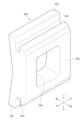
- the plate member 65 is a frame-like plate body for holding the upholstery 2b, and is mounted on the lever mounting member .
- the plate member 65 is provided between the cover member 60 and the lever mounting member 70 in the vertical direction, and is arranged so as to surround the operating lever 50 .
- the plate member 65 is supported from below by the side flange portion 70e, the front flange portion 70f, and the rear flange portion 70g of the lever mounting member 70, as shown in FIG. Further, it is laterally supported by the plate support portion 75 of the lever mounting member 70 .
- the plate member 65 supports the skin material 2b from below. Specifically, the plate member 65 and the cover member 60 sandwich the outer peripheral portion of the skin opening hole 2c of the skin material 2b from above and below.
- the operating lever 50 is attached so as to be exposed from the skin opening hole 2c formed in the outer surface of the skin material 2b.
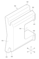
- the lever mounting member 70 is a storage plate that rotatably supports the operating lever 50, and is mounted on the upper portion of the back frame 10 at a lateral position.
- the lever mounting member 70 has a box shape, as shown in FIG. More specifically, the lever mounting member 70 includes left and right side wall portions 70a spaced apart in the seat width direction, a front wall portion 70b connecting the front ends of the left and right side wall portions 70a, and the left and right side wall portions 70a. It has a rear wall portion 70c that connects the rear end portions, and a bottom wall portion 70d that connects the lower end portions of the left and right side wall portions 70a, the front wall portion 70b, and the rear wall portion 60c.
- the lever mounting member 70 includes left and right side flange portions 70e projecting outward in the seat width direction from the upper ends of the left and right side wall portions 70a, and a front flange projecting forward from the upper ends of the front wall portions 70b. and a rear flange portion 70g projecting rearward from the upper end portion of the rear wall portion 70c.
- the lever mounting member 70 is formed in front portions of the left and right side wall portions 70 a and has left and right shaft support portions 71 (shaft support holes) for supporting the lever rotation shaft 51 . Further, the lever mounting member 70 is formed at the rear portion of the left and right side wall portions 70 a , projects outward in the seat width direction from each side wall portion 70 a , and has left and right engagement protrusions 72 that engage with the cover engagement holes 62 . have. Further, the lever mounting member 70 has an opening 73 which is provided in the central portion of the left and right side wall portions 70 a and which is formed at a position facing the engaging portion 54 of the operating lever 50 .
- the openings 73 are formed by notching upward from the lower ends of the left and right side wall portions 70a, and are elongated openings in the vertical direction. can be inserted from the outside of the By using the opening 73 , the connecting link 80 (lever engaging portion 82 ) can be connected to the engaging portion 54 of the operating lever 50 .
- the lever mounting member 70 is formed on the upper surface of each of the inner ends of the flanges 70e, 70f, and 70g, protrudes toward the cover member 60, and is attached to the support projection 64 of the cover member 60. It has a cover support portion 74 .
- the cover support portions 74 are assembly projections, and are formed in plurality at intervals along the edge portions (inner edge portions) of the flange portions 70e, 70f, and 70g.
- the lever mounting member 70 is formed on the upper surface of the inner end of each of the flanges 70e, 70f, and 70g, protrudes toward the plate member 65, and extends on the inner surface of the plate member 65. It has a plate support portion 75 that supports the plate member by coming into contact with it.
- the plate support portion 75 is provided adjacent to the cover support portion 74 , and specifically, is arranged outside the cover support portion 74 .
- a plurality of plate support portions 75 are formed at intervals along the inner surface of the plate member 65 and extend along the inner surface of the plate member 65 .
- the lever mounting member 70 is formed at the lower ends of the left and right side wall portions 70a, and is fitted with portions 98b, 98c, and 99b provided on the lock covers 98 and 99 ( It has fitting portions 76, 77, and 78 (fitting holes) that fit into the fitting protrusions.
- the first fitting portion 76 fits into the first fitted portion 98 b at the upper end of the first lock cover 98 .
- the second fitting portion 77 is arranged at a rear position relative to the first fitting portion 76 and is fitted to the second fitted portion 99 b at the upper end portion of the second lock cover 99 .
- the third fitting portion 78 is arranged at a rear position relative to the second fitting portion 77 and is fitted to the third fitted portion 98 c at the upper end portion of the first lock cover 98 .
- the lever mounting member 70 has a projecting portion 79 projecting from the rear wall portion 70c toward the rear side of the seat.
- the projecting portion 79 is a portion that supports the skin material 2b by coming into contact with the outer peripheral portion of the skin opening hole 2c in the skin material 2b.
- the projecting portion 79 is formed in a hollow shape when viewed from the side of the seat.
- the projecting portion 79 is arranged at different positions in the vertical direction, and includes a top wall portion 79a and a bottom wall portion 79b projecting from the rear surface of the rear wall portion 70c to the seat rear side, and a rear wall portion 79a. It has a support wall portion 79c that connects the end portion and the rear end portion of the bottom wall portion 79b and supports the upholstery material 2b.
- the highest plate support portion 75 among the plurality of plate support portions 75 is arranged above the body portion of the lever mounting member 70 . . By doing so, the plate member 65 can be more firmly attached to the lever mounting member 70 .
- the lever mounting member 70 has an engaging convex portion 72 that engages with a cover engaging hole 62 (engaged portion) provided on the outer surface of the cover member 60. ing. A plurality of engaging projections 72 are arranged between the plurality of plate supporting portions 75 . By doing so, the cover member 60 can be stably engaged with the lever mounting member 70 .
- the lever mounting member 70 is formed around the engaging projection 72 and is positioned to position the cover engaging hole 62 at a position where it engages the engaging projection 72 . It has a portion 72a.
- the positioning portion 72a is a recessed positioning recess. By doing so, it is possible to facilitate engagement of the cover member 60 with the lever mounting member 70 .
- connection link 80 connects the operating lever 50 and the locking device 90 (the transmission member 92), and moves the locking device 90 from the locked state to the unlocked state in response to the operation of the operating lever 50.
- It is a connecting member made of resin that acts to switch to The connecting link 80 is held by a flexible plate-like position holding member 89 .
- the connecting link 80 extends vertically between the operating lever 50 and the locking device 90 , is connected to the operating lever 50 and the locking device 90 , and is stored inside the lever mounting member 70 .
- the upper portion of the connecting link 80 enters the inside of the lever mounting member 70 through an opening 73 formed in the outer surface of the lever mounting member 70, and the operating lever 50 (engagement portion). 54).
- the lower portion of the connecting link 80 is covered from the sides by lock covers 98 and 99, and is connected to the locking device 90 (the transmission member 92 and the biasing spring 96).
- the connecting link 80 includes a main body portion 81 that is elongated in the vertical direction, and a side surface (left side surface) of the upper portion of the main body portion 81 that protrudes from the operation lever 50 ( a lever engaging portion 82 that engages with the engaging portion 54); a lock connecting portion 83 that protrudes from the side surface (left side surface) of the lower portion of the main body portion 81 and connects to the locking device 90 (the transmission member 92); A spring mounting portion 84 is provided, which protrudes from the side surface (right side surface) of the lower portion of 81 opposite to the lock connecting portion 83 side and mounts the biasing spring 96 thereon.
- the connecting link 80 protrudes rearward from the left and right side surfaces of the central portion of the main body portion 81, and includes an attachment portion 85 for mounting the position holding member 89, and a rear surface of the central portion of the main body portion 81, protruding rearward from the position holding member.
- An engaging projection 86 (engaging portion) for engaging with the engaging hole 89c (engaged portion) of 89 is further provided.
- the lever engaging portion 82 is, for example, a snap-fit engaging protrusion that protrudes from the side surface of the main body portion 81 toward the operation lever 50 and engages the engaging portion 54. is engaged.
- the lever engaging portion 82 includes an engaging main body portion 82a having a substantially elliptical cross-section having a long axis in the vertical direction, and an engaging main body portion 82a that further protrudes from the distal end portion of the engaging main body portion 82a and has a width of the engaging main body portion 82a. and an engaging claw 82b formed to extend outward in the direction.
- a slit hole 82c formed along the direction in which the lever engaging portion 82 protrudes is formed in the central portion of the lever engaging portion 82 in the width direction.
- the engagement portion 54 (engagement hole) of the operating lever 50 has a width in the extending direction (vertical direction) of the connecting link 80, which is in the direction intersecting the extending direction of the connecting link 80 (front-rear direction). is larger than the width in That is, the engaging portion 54 has a hole shape corresponding to the shape of the lever engaging portion 82 (elliptical shape elongated vertically). More specifically, the vertical width of the engaging portion 54 is slightly larger than the vertical width of the lever engaging portion 82 .
- the connecting link 80 can be easily attached to the operating lever 50 . That is, the connecting link 80 can be attached while adjusting the vertical position of the connecting link 80 with respect to the operating lever 50 . Moreover, after the connection link 80 is attached, the connection link 80 can be firmly connected by snap fit fitting.
- the lock connecting portion 83 is, for example, a snap-fit connecting protrusion that protrudes from the side surface of the main body portion 81 toward the transmission member 92 and engages with the connecting hole 92a. be.
- the lock connecting portion 83 has the same shape as the lever engaging portion 82, and has an engaging body portion 83a, an engaging claw 83b, and a slit hole 83c.
- the spring assembly portion 84 is an assembly protrusion that protrudes from the side surface of the main body portion 81 toward the biasing spring 96 and is attached to the upper end portion of the biasing spring 96 .
- the spring mounting portion 84 is formed so as to widen toward its protruding tip portion 84a. A portion of the spring mounting portion 84 to which the biasing spring 96 is mounted is narrower than the projecting tip portion 84a. By doing so, the biasing spring 96 is less likely to come off from the spring mounting portion 84 in the mounting direction of the biasing spring 96 .
- the mounting portion 85 has a hook shape, and the left and right mounting body portions 85a protrude rearward from the left and right side surfaces of the main body portion 81. and a hook portion 85b protruding upward.
- the position holding member 89 can be attached to the attachment portion 85 from above.
- the mounting portion 85 can support the position holding member 89 from below. Further, the body portion 81 and the mounting portion 85 can hold the position holding member 89 so as to sandwich the position holding member 89 in the seat front-rear direction.
- the engaging convex portion 86 is provided between the mounting portions 85 (left and right mounting main body portions 85 a ) and arranged slightly below the mounting portion 85 .
- a position holding member 89 (engagement hole 89c) can be attached to the engagement protrusion 86 from behind. Further, the engaging convex portion 86 can hold the position holding member 89 so as not to be displaced in the sheet width direction. In other words, the mounting portion 85 and the engaging protrusions 86 can hold the position holding member 89 in the seat width direction.
- the connecting link 80 further includes a reinforcing portion 87 formed on the side surface of the body portion 81 in the seat width direction and extending along the extending direction of the connecting link 80 .
- the reinforcing portion 87 is a recessed reinforcing recess.
- the lever engaging portion 82, the lock connecting portion 83, and the spring assembly portion 84 are arranged at positions different from the reinforcing portion 87 in the vertical direction. By doing so, the rigidity of the entire connecting link 80 can be improved in a well-balanced manner.
- thicknesses of the lever engaging portion 82, the lock connecting portion 83 and the spring mounting portion 84 in the connecting link 80 can be ensured.
- the reinforcing portion 87 is formed with a through hole 88 that penetrates the connecting link 80 (body portion 81).
- the through hole 88 and the spring attachment portion 84 (lock connection portion 83 ) are arranged side by side on the side surface of the connection link 80 .
- the weight of the connecting link 80 can be reduced by the through holes 88 .
- the position holding member 89 is a flexible plate-like member made of resin, and extends long in the extending direction (vertical direction) of the connecting link 80. It is attached only to the connecting link 80 along the connecting link 80 .
- the position holding member 89 holds the position of the connecting link 80 by bending in a direction orthogonal to the extending direction (vertical direction) of the position holding member 89 .
- the position holding member 89 is housed and attached to the connecting link 80 (attaching portion 85).
- the position holding member 89 is arranged along the outer surface (rear surface) of the connecting link 80, and includes a main body portion 89a extending in the vertical direction and a central portion of the main body portion 89a protruding left and right outward. ), and an engagement hole 89c that is formed slightly below the projection 89b in the central portion of the main body 89a and engages with the engagement projection 86.
- the position holding member 89 includes a bent portion 89d formed by bending the upper end of the main body portion 89a rearward, and a bent portion 89e formed by bending the lower end of the main body portion 89a rearward. I have more.
- the bending portion 89d is formed by folding back the upper end portion of the main body portion 89a rearward, and is arranged at a position facing the main body portion 89a in the seat front-rear direction. Further, the flexible portion 89d is arranged at a position facing the connecting link 80 in the seat front-rear direction.
- the length of the position holding member 89 in the seat front-rear direction is shorter than the length of the connecting link 80 in the seat front-rear direction. By doing so, the position holding member 89 can be arranged compactly.
- the position holding member 89 and the connecting link 80 pass through the opening 73 of the lever mounting member 70 and are arranged therein.
- a lever engaging portion 82 of the connecting link 80 is engaged with the operating lever 50 (engaging portion 54).
- the opening 73 is formed so as to widen in the sheet width direction as it moves away from the operation lever 50 . By doing so, it becomes easy to assemble the connecting link 80 to the operating lever 50 using the opening 73 .
- the inner side surface of the opening 73 of the lever mounting member 70 includes a first inner side surface 73a formed in a flat shape and an outer side in the seat width direction from the first inner side surface 73a. and a second inner side surface 73b formed so as to extend in an inclined manner.
- the bending portion 89d of the position holding member 89 holds the position of the connecting link 80 by contacting the first inner side surface 73a of the opening 73 and bending. By doing so, the position holding member 89 can preferably hold the position of the connecting link 80 .
- the position holding member 89 includes a portion of the connecting link 80 that is assembled to the locking device 90 (the lock connecting portion 83) and a portion that engages with the operating lever 50 (the lever engaging portion). 82). By doing so, the position holding member 89 can hold the position of the connecting link 80 in a well-balanced manner.
- connection link 80 in the above configuration, as shown in FIG. 11, in the connection link 80, the body portion 81, the lever engagement portion 82, the lock connection portion 83, and the spring assembly portion 84 are integrally formed. By doing so, the number of parts of the switching device 40 can be reduced.
- the connecting link 80 and the position holding member 89 are formed separately, but this is not a particular limitation.
- the connecting link 80 and the position holding member 89 may be integrally formed from the same material (the same resin material). By doing so, the number of component parts can be reduced.
- the lock device 90 is mounted rotatably about a lock rotation shaft 94 extending in the width direction of the seat.
- a lock member 91 that is detachably engaged and a second lock rotation shaft 95 that is disposed above the lock member 91 and extends in the seat width direction is attached so as to be rotatable. 80) to the lock member 91, and a second transmission member 92 arranged inside the lock member 91 (transmission member 92) in the seat width direction to transmit the operation of the transmission member 92 to the lock member 91.
- the locking device 90 further includes a biasing spring 96 that is arranged below the connecting link 80 and assembled with the connecting link 80 to bias the connecting link 80 toward the lock member 91 .
- the lock member 91 and the transmission member 92 are arranged at overlapping positions in the seat width direction.
- the transmission member 92 is connected to the operating lever 50 via the connecting link 80 and rotates as the operating lever 50 operates.
- the second transmission member 93 rotates.
- the lock member 91 rotates between the "locked position” and the "unlocked position”. Details of the lock member 91, the transmission member 92, and the second transmission member 93 will be described later.
- the lock covers 98 and 99 are covers that cover the lock member 91, the transmission member 92, the second transmission member 93 and the urging spring 96 from the sides, as shown in FIGS.
- the lock covers 98 and 99 are arranged below the lever mounting member 70 and assembled to the side surface (right side surface) of the lever mounting member 70 in the seat width direction.
- the first lock cover 98 is attached to the lever mounting member 70 and pivotally supports the lock pivot shaft 94 and the second lock pivot shaft 95 .
- the second lock cover 99 is arranged outside the first lock cover 98, is assembled to the lever mounting member 70 and the first lock cover 98, and is pivoted about the lock pivot shaft 94 and the second lock pivot shaft 95. supporting.
- the first lock cover 98 is a box-shaped resin cover, as shown in FIGS. A first fitted portion 98 b that projects toward the first fitting portion 76 and fits into the first fitting portion 76 ; and a third fitted portion 98c.
- the first lock cover 98 is formed on the side surface of the main body portion 98a, and is formed at a position above the shaft support hole 98d on the side surface of the main body portion 98a. , a second shaft support hole 98e for supporting the second lock rotation shaft 95, and a side surface of the body portion 98a. It further has a cover assembly portion 98f and a second cover assembly portion 98g to be assembled.
- the cover assembling portion 98f is an assembling protrusion arranged between the shaft support hole 98d and the second shaft support hole 98e in the vertical direction, and is located between the first fitted portion 98b and the third fitted portion 98b in the front-rear direction. It is arranged between the portions 98c.
- the second cover assembly portion 98g extends vertically and is arranged between the first fitted portion 98b and the third fitted portion 98c in the front-rear direction.
- the second lock cover 99 is a plate-shaped metal cover, and includes a main body portion 99a and a second locking cover that protrudes from the upper end portion of the main body portion 99a toward the lever mounting member 70 and is fitted to the second fitting portion 77 .
- a fitted portion 99b, a shaft support hole 99c formed in the side surface of the main body portion 99a for supporting the lock rotation shaft 94, and a second shaft support hole 99d for supporting the second lock rotation shaft 95. have.
- the second lock cover 99 is formed on the side surface of the main body portion 99a, and is assembled to the first lock cover 98 (the cover assembly portion 98f, the second cover assembly portion 98g), respectively. It further has a portion 99f.
- the assembled portion 99e is an assembly projection.
- the second assembled portion 99f is a bent portion formed by bending an end portion of the body portion 99a.
- the first fitting portion 76 (first fitted portion 98b) and the second fitting portion 77 (second fitted portion 99b) each have a lock cover. It extends in a direction orthogonal to the fitting direction (seat width direction) of 98 and 99, and extends in a direction crossing (perpendicular to) each other.
- the first fitting portion 76 and the second fitting portion 77 are arranged at different positions in the vertical direction and at different positions in the seat front-rear direction. By doing so, the fitting strength of the lock covers 98 and 99 to the lever mounting member 70 can be improved.
- FIG. It is arranged on the side opposite to the second fitting portion 77 (the second fitted portion 99b). Also, the first fitting portion 76 and the third fitting portion 78 are elongated in the same direction. The second fitting portion 77 is arranged between the first fitting portion 76 and the third fitting portion 78 in the seat front-rear direction. By doing so, the fitting strength of the lock covers 98 and 99 to the lever mounting member 70 can be increased.
- the first fitting portion 76, the second fitting portion 77, and the third fitting portion 78 are fitted in the same direction (seat width direction).
- a lever mounting member 70 and lock covers 98 and 99 are assembled. By doing so, the operation of assembling the lock covers 98 and 99 to the lever mounting member 70 is facilitated. In addition, it becomes easy to automate the assembly work.
- the first lock cover 98 is formed so as to protrude from the side surface of the outer edge portion toward the lock member 91 (transmission member 92) so as to support the lock member 91 (transmission member 92). It has a cover flange 98h arranged so as to surround it.
- the first fitting portion 76, the second fitting portion 77, and the third fitting portion 78 are arranged on the side surface of the first lock cover 98 outside the cover flange 98h.
- the first lock cover 98 is formed to protrude from the side surface of the outer edge portion toward the lock member 91, connecting the cover flange 98h and the first fitted portion 98b. and a second reinforcing portion 98j connecting the cover flange 98h and the third fitted portion 98c.
- the fitting strength of these fitted portions 98b and 98c can be increased.
- the lock member 91 is a member that rotates about a lock rotation shaft 94 between a "locked position” and an “unlocked position” moved below the locked position. is. When it is in the "locked position", it abuts against the transmission member 92, and its movement is restricted by the transmission member 92, so that it is arranged in the locked position.
- the lock member 91 is arranged on the opposite side of the striker engaging portion 91a that engages with the striker 41 and the striker engaging portion 91a with the lock rotation shaft 94 therebetween. and an abutting portion 91b.
- the lock member 91 is arranged on the opposite side of the striker engaging portion 91a with the lock rotary shaft 94 interposed therebetween, and is connected to the second transmission member 93 by a connecting pin 97 extending in the seat width direction.
- the transmission member 92 rotates around the second lock rotation shaft 95 to move between a “restricted position” at which the movement of the lock member 91 is restricted and a “restricted position” away from the lock member 91 . It is a member that switches between the “release position”.
- the transmission member 92 has a connection hole 92a connected to the connection link 80 (the lock connection portion 83) and a connection hole 92a on the opposite side (lower side) of the connection hole 92a with the second lock rotation shaft 95 interposed therebetween. ) and has a protrusion 92b that protrudes toward the second transmission member 93 side.
- the transmission member 92 is connected to the second transmission member 93 by inserting the projection 92b into a projection insertion hole 93b formed in the second transmission member 93 .
- the second transmission member 93 is a member that is interposed between the lock member 91 and the transmission member 92 and transmits the operation of the transmission member 92 to the lock member 91 as shown in FIGS.
- the second transmission member 93 includes a pin support hole 93a that pivotally supports the connecting pin 97, a protrusion insertion hole 93b provided above the pin support hole 93a and connected to the protrusion 92b, a pin and a spring support portion 93c that is provided between the support hole 93a and the projection insertion hole 93b and supports the lower end portion of the biasing spring 96.
- the locking device 90 moves to the "unlocked position" through the “intermediate position”. Specifically, first, the connecting link 80 is pulled upward as the operating lever 50 rotates, and moves upward against the biasing force of the biasing spring 96 . As the connecting link 80 moves upward, the transmission member 92 rotates upward around the second lock rotation shaft 95 and pulls the second transmission member 93 upward via the projection 92b. At this time, the transmission member 92 is separated from the lock member 91 . As the transmission member 92 rotates, the second transmission member 93 moves upward and pulls the lock member 91 upward through the connecting pin 97 .
- the lock member 91 rotates about the lock rotation shaft 94 and moves away from the striker 41 . By doing so, the lock member 91 switches from the locked state in which it is engaged with the striker 41 to the unlocked state.
- the operating lever 50 when the operating lever 50 is released from the state operated by the passenger, the operating lever 50 returns to the position housed inside the lever mounting member 70 again by the biasing force of the biasing spring 96 . Further, the lock member 91 also returns to the position where it engages with the striker 41 (engageable position). That is, the operating lever 50 and the lock device 90 are returned to the "lock position".
- the "moving state" of the seat body is described as corresponding to the “storage state", but it is not particularly limited.
- the “moving state” may correspond to a “reclining state” in which the seat body (seat back) is tilted backward to a predetermined position.
- it may correspond to a "front-rear movement state” in which the seat body is moved in the seat front-rear direction from the normal state, and a “tip-up state” in which the seat body (seat back) is flipped up to a predetermined position.
- the "moving state” may be a “height changing state” in which the height position of the seat body is changed.
- the “moving state” may be an "ottoman unfolded state” in which the leg support members, which are part of the seat body, are unfolded.
- the operating lever 50 is attached to the left side portion of the upper surface of the seatback 1, but it is not particularly limited and can be changed.
- the operating lever 50 may be attached to the right portion of the upper surface of the seatback 1, or may be attached to the left outer surface, the right outer surface, or the rear surface of the seatback 1.
- the operating lever 50 may be attached to the front surface, bottom surface, or rear surface of the seat cushion 2 .
- it may be attached to the left outer surface or right outer surface of the seat cushion 2 .
- the operation lever 50 is a lever elongated in the seat front-rear direction, and a lever rotation shaft 51 is pivotally supported at the front end portion (base end portion) thereof.
- the rear end portion of the operating lever 50 may be supported by a lever rotating shaft.
- the rear end portion of the operating lever 50 corresponds to the "base end portion”
- the front end portion thereof corresponds to the "tip end portion”.
- the operation lever 50 may be a lever elongated in the seat width direction
- a lever rotation shaft elongated in the seat front-rear direction may be supported at one end portion in the seat width direction. In that case, one end portion of the operating lever 50 corresponds to the "base end portion", and the other end portion corresponds to the "tip end portion".
- the biasing spring 96 is a vertically elongated biasing spring (tension spring), but it is not particularly limited. That is, any biasing member that can bias the connecting link 80 toward the locking device 90 can be changed as appropriate.
- the biasing spring 96 biases the connecting link 80 toward the lock device 90, but is not particularly limited.
- the biasing spring 96 may bias the connecting link 80 toward the operating lever 50 side. In that case, the operating lever 50 is not operated to the side opposite to the locking device 90 side as shown in FIGS. It should be operated to push out to.
- the lock cover that covers the lock device 90 is divided into a first lock cover 98 and a second lock cover 99, but this is not a limitation.
- one lock cover may be used, or three or more lock covers may be used.
- the first fitted portion 98b of the first lock cover 98 and the second fitted portion 99b of the second lock cover 99 are arranged in directions perpendicular to each other. However, it is not particularly limited as long as it extends in directions intersecting each other.
- the plate support portion 75 of the lever mounting member 70 supports the frame-shaped plate member 65 by coming into contact with the inner surface of the frame-shaped plate member 65, but is not particularly limited. not something.
- the plate support portion 75 may support the plate member 65 by coming into contact with the outer surface of the plate member 65 .
- the cover member 60 and the lever mounting member 70 may be replaced with the cover member 160 and the lever mounting member 170, respectively, as in the modification shown in FIG.
- the lever mounting member 170 has a latching portion 174 that latches onto a latching claw 162 provided on the outer surface of the cover member 160 .
- the latching portion 174 is composed of a latching hole 174a formed in the side wall portion 170a of the lever mounting member 170 and a latching support portion 174b formed on the bottom surface of the side flange portion 170e.
- the vehicle seat includes a seat body having a seat back and a seat cushion, and the seat body can be switched between a normal state and a moving state in which the seat body is moved from the normal state.
- a lock device provided on the vehicle seat for locking movement of the seat body in the normal state; and a lock device provided on the vehicle seat for releasing the locked state of the lock device.
- a position holding member for holding the position of the connecting member, the connecting member extending between the locking device and the operating lever, the position holding member extending in the extending direction of the connecting member. and attached to the connecting member along the connecting member.
- the moving state is a stowed state in which the seat back is stowed and moved toward the floor of the vehicle body, and the locking device is detachably engaged with a striker provided on the vehicle body or the vehicle seat. and a lock member that moves between a lock position for locking the storage operation of the seat back and an unlock position, wherein the position holding member has flexibility and extends in the extending direction of the position holding member. It is preferable that the position of the connecting member is held by bending in a direction perpendicular to .
- the connecting member includes an attachment portion for attaching the position holding member from the extending direction of the connecting member and an engaged portion provided on the position holding member from a direction different from the extending direction. and an engaging portion for engaging the .
- the connecting member includes the mounting portion for mounting the position holding member in the vertical direction, and a position below the mounting portion for engaging the engaged portion in the seat front-rear direction. and the engaging portion, and the lower end portion of the position holding member may be bent to the side opposite to the connecting member side.
- the connecting member is a connecting link that extends vertically between the locking device and the operating lever, and the position holding member extends vertically along the connecting member. It is preferable that the position holding member is elongated, and the length of the position holding member in the seat front-rear direction is shorter than the length of the connecting member in the seat front-rear direction. With the above configuration, the position holding member can be arranged compactly.
- the position holding member is formed in a plate shape and arranged along the outer surface of the connecting member.
- the position holding member can be formed relatively thin. Therefore, the position holding member can be arranged compactly.
- the vehicle seat is provided with a lever mounting member for mounting the operating lever, the operating lever is housed inside the lever mounting member, and the lever mounting member has a lever rotating shaft interposed therebetween.
- An opening is formed in the outer surface of the lever mounting member for allowing the connecting member to pass therethrough and for connecting the connecting member to the operating lever. It is preferable that it is formed so that the width becomes wider as the distance from the lever increases. With the above configuration, it becomes easy to assemble the connecting member to the operating lever using the opening provided in the lever mounting member.
- the position holding member passes through the opening together with the connecting member and is arranged inside the lever mounting member, and the inner side surface of the opening is formed as a flat first inner side surface. and a second inner surface provided outside the first inner surface and formed to extend in an inclined manner, the position holding member having a flexible bending portion, It is preferable that the flexible portion is bent in contact with the first inner side surface of the opening to hold the position of the connecting member.
- the bending portion of the position holding member bends in contact with the planar first inner surface of the lever mounting member. Therefore, it becomes easier for the position holding member to hold the position of the connecting member.
- the connecting member is a connecting link that extends vertically between the locking device and the operating lever, and the position holding member extends vertically along the connecting member. It is preferably elongated and attached only to the connecting member.
- the connecting member and the position holding member are integrally formed from the same resin material. With the above configuration, the number of component parts can be reduced.
- the vehicle seat includes a seat body having a seat back and a seat cushion, and is switchable between a normal state and a moving state in which the seat body is moved from the normal state.
- a seat comprising: a locking device provided on the vehicle seat for locking movement of the seat body in the normal state; and a locking device provided on the vehicle seat for releasing the locked state of the locking device.
- the connecting member that connects the locking device and the operating lever and acts to switch the locking device from the locked state to the unlocked state in response to the operation of the operating lever; and the connecting member and a biasing member that is assembled to and biases the connecting member toward the lock device side or the operating lever side, the connecting member having an assembling portion for assembling the biasing member, and the connecting
- the body portion of the member and the attachment portion are integrally formed.
- the connecting member has an assembly portion for mounting the biasing member, and the body portion of the connecting member and the assembly portion are integrally formed. Therefore, separate members can be eliminated as much as possible when assembling the components (connecting member and biasing member). Also, it becomes easier to assemble the biasing member to the connecting member.
- the moving state is a stowed state in which the seat back is stowed and moved toward the floor of the vehicle body, and the locking device is detachably engaged with a striker provided on the vehicle body or the vehicle seat. and a lock member that moves between a lock position for locking the storage operation of the seat back and an unlock position, wherein the assembly portion extends from the side surface of the main body portion of the connection member toward the biasing member. preferably an assembly projection projecting from the bottom and assembled to one end of the biasing member.
- the connecting member is a connecting link that extends vertically between the locking device and the operating lever
- the biasing member is a biasing spring that is the connecting member.
- the mounting portion is disposed in the lower portion of the connecting member and mounted to the upper end portion of the biasing member. Since the connecting member and the biasing member are arranged so as to line up in the vertical direction as described above, the connecting member and the biasing member can be arranged compactly in the seat front-rear direction.
- the assembly portion protrudes from the side surface of the main body portion of the connecting member toward the biasing member, and is formed so as to become wider toward the protruding distal end portion of the assembly portion. It is preferable that the portion to which the biasing member is attached is narrower than the protruding tip portion of the attachment portion. With the above configuration, the biasing member can be firmly attached to the connecting member. Moreover, it is possible to prevent the biasing member from coming off the connecting member.
- the connecting member extends vertically between the locking device and the operating lever, and the connecting member is formed on the side surface of the connecting member and extends in the extending direction of the connecting member.
- the reinforcing portion is a concave reinforcing concave portion or a convex reinforcing convex portion
- the mounting portion is formed on a side surface of the connecting member and extends vertically along the It is preferable that it is arranged at a position different from that of the reinforcing portion.
- the thickness of the mounting portion can be ensured when the reinforcement portion has a concave shape.
- the size of the connecting member (reinforcing portion) can be reduced.
- connection member has the through hole as described above, the weight of the connection member can be reduced.
- the connecting member can have a simple configuration.
- the connecting member has a convex lever engaging portion for engaging with an engaging hole provided in the operating lever, and the width of the engaging hole in the extending direction of the connecting member is , the width of the engaging hole in a direction intersecting with the extending direction of the connecting member is preferably larger than that of the engaging hole.
- a position holding member that is attached to the connecting member and holds the position of the connecting member is provided, the connecting member is elongated in the vertical direction between the locking device and the operating lever, and the The position holding member is preferably arranged between a portion of the connecting member that is assembled with the locking device and a portion that engages with the operating lever.
- the connecting member has an attachment portion for attaching the position holding member, and the position holding member is housed in and attached to the attachment portion.
- the position holding member is formed in a plate shape, extends in the extending direction of the connecting member, and is arranged along the outer surface of the connecting member.
- the vehicle seat includes a seat body having a seat back and a seat cushion, and is switchable between a normal state and a moving state in which the seat body is moved from the normal state.
- a seat comprising: a lock device for locking movement of the seat body in the normal state; a lock cover covering the lock device; a lever attachment member attached to the vehicle seat; an operation lever attached to operate to release the locked state of the lock device, wherein the lever attachment member is a first fitting member that is fitted to a first fitted portion provided on the lock cover; and a second fitting portion that fits into a second fitted portion provided on the lock cover, and the first fitting portion and the second fitting portion are respectively connected to the lock cover.
- the lever mounting member is fitted to the lock cover by a plurality of fitting portions, and the first fitting portion and the second fitting portion each extend in a direction orthogonal to the fitting direction of the lock cover. and extend in directions that intersect each other. Since the first fitting portion and the second fitting portion extend in different directions in this way, even when loads are applied from various directions, for example, the fitting structure is stronger than the conventional structure. can do.
- the moving state is a stowed state in which the seat back is stowed and moved toward the floor of the vehicle body, and the locking device is detachably engaged with a striker provided on the vehicle body or the vehicle seat. and a locking member that moves between a locking position for locking the storage operation of the seatback and an unlocking position, wherein the first fitting portion and the second fitting portion extend in directions perpendicular to each other.
- the lock cover is assembled to the lever mounting member in the seat width direction, the first fitting portion and the second fitting portion are arranged at different positions in the vertical direction, and It is good if they are placed in different positions.
- a connecting member is provided which connects the locking device and the operating lever and acts to switch the locking device from the locked state to the unlocked state in response to the operation of the operating lever, and the lever attachment member
- the lock cover further includes a third fitting portion that fits into a third fitted portion provided on the lock cover, and the third fitting portion is attached to the first fitting portion and the second fitting portion with respect to the connecting member. It is preferable that it is arranged on the side opposite to the fitting portion side.
- the first fitting portion and the third fitting portion are elongated in the same direction.
- the lock cover is assembled to the lever mounting member in the seat width direction, and the second fitting portion is arranged between the first fitting portion and the third fitting portion in the seat front-rear direction. It's good to be With the above configuration, the lever mounting member and the lock cover can be firmly assembled in a well-balanced manner.
- the lock cover has a first lock cover that covers the lock device, and a second lock cover that is attached to a side surface of the first lock cover, and the first fitted portion and the third lock cover.
- the fitted portion may be formed in the first lock cover, and the second fitted portion may be formed in the second lock cover. Since the lever mounting member, the first lock cover, and the second lock cover are fitted to each other by the plurality of fitting portions as described above, these components can be assembled stably and firmly.
- the lever mounting member and the lock cover are assembled by fitting the first fitting portion, the second fitting portion, and the third fitting portion in the same direction.
- the above configuration facilitates the operation of assembling the lock cover to the lever mounting member. In addition, it becomes easy to automate the assembly work.
- the lock cover has a cover flange formed so as to protrude from the side surface of the outer edge portion of the lock cover toward the lock device and arranged to surround the lock device.
- the joint portion, the second fitting portion, and the third fitting portion may be arranged outside the cover flange on the side surface of the lock cover.
- the lock cover is formed so as to protrude from the side surface of the outer edge portion of the lock cover toward the lock device, and includes a first reinforcing portion that connects the cover flange and the first fitting portion, and the lock. It is preferable to have a second reinforcing portion formed so as to protrude from the side surface of the outer edge portion of the cover toward the locking device and connect the cover flange and the third fitting portion.
- the vehicle seat includes a seat body having a seat back and a seat cushion, and is switchable between a normal state and a moving state in which the seat body is moved from the normal state.
- a seat comprising: a locking device provided on the vehicle seat for locking movement of the seat body in the normal state; a lever mounting member mounted on the vehicle seat; and a lever mounting member mounted on the vehicle seat. an operating lever that operates to release the locked state of the locking device; a cover member that is arranged between the lever mounting member and the operating lever and covers the operating lever; and the lever mounting member and the cover member.
- the lever mounting member extends from the body portion of the lever mounting member to the plate It is preferable to have a protruding portion that protrudes toward the member side and supports the plate member by coming into contact with the inner side surface or the outer side surface of the plate member.
- the lever mounting member has a plate supporting portion that protrudes from the main body portion of the lever mounting member toward the plate member side and supports the plate member by contacting the side surface of the plate member. Therefore, when assembling the plate member to the lever mounting member, there is no need to perform separate processing on the plate member side. That is, it is possible to simplify the assembly structure compared to the conventional art.
- the moving state is a stowed state in which the seat back is stowed and moved toward the floor of the vehicle body, and the locking device is detachably engaged with a striker provided on the vehicle body or the vehicle seat. and a lock member that moves between a lock position for locking the storage operation of the seat back and an unlock position, and the plate support portion preferably extends along the side surface of the plate member.
- a plurality of the plate supporting portions are formed at intervals along the side surface of the plate member, and the highest plate supporting portion among the plurality of plate supporting portions is attached to the lever. It is preferable that it is arranged at a position above the main body of the member. With the above configuration, the plate member can be more firmly attached to the lever mounting member.
- the lever mounting member has an engaging portion that engages with the engaged portion provided on the side surface of the cover member, and the plate supporting portion is spaced along the side surface of the plate member. and the engaging portion is preferably arranged between the plurality of plate supporting portions. Since the engaging portion is arranged between the plurality of plate supporting portions as described above, the cover member can be stably engaged with the lever mounting member.
- the engaging portion is an engaging convex portion that engages with an engaging hole provided in the side surface of the cover member, and the lever mounting member is formed around the engaging convex portion, It is preferable to have a positioning portion for positioning the engagement hole at a position to engage with the engagement protrusion. With the above configuration, it is possible to easily engage the cover member with the lever mounting member.
- the lever mounting member has a cover supporting portion that protrudes from the main body portion of the lever mounting member toward the cover member side and supports the cover member by coming into contact with the surface of the cover member,
- the cover supporting portion is preferably provided adjacent to the plate supporting portion.
- the lever mounting member projects from the main body portion of the lever mounting member toward one side in the front-rear direction of the seat, and supports the surface material by coming into contact with the outer peripheral portion of the surface opening hole in the surface material. It is preferable to have an overhang. With the above configuration, the overhanging portion of the lever mounting member can support one end portion of the upholstery in the front-rear direction, so that the upholstery can be stretched. By doing so, it is possible to suppress the occurrence of wrinkles in the skin material.
- the overhanging portions are arranged at different positions in the vertical direction, and include an upper wall portion and a bottom wall portion respectively projecting from the rear surface of the main body portion of the lever mounting member toward the seat rear side, and a rear end of the upper wall portion. and a support wall portion that connects the rear end portion of the bottom wall portion and supports the upholstery material, and is formed in a hollow shape when viewed from the side of the seat.
- the projecting portion of the lever mounting member is hollow, the weight of the lever mounting member can be reduced.
- the plate member is a frame-shaped plate body, and the plate support portion supports the plate member by coming into contact with the inner side surface of the plate member, and along the inner side surface of the plate member. It is preferable that it extends and that a plurality of them are arranged at intervals.
- the frame-shaped plate member can be attached to the lever mounting member with a simple structure. Also, the plate member can be firmly assembled.
- the lever mounting member has a latching portion that is latched onto the latching portion provided on the side surface of the cover member, and one of the latching portion and the latching portion is a latching claw. and preferably hooked to the other of the hooking portion and the hooked portion.
- the vehicle seat S2 includes a switching device that switches the state of the seat body by being detachably connected to a striker of the vehicle body, and a cushioning member that contacts the striker. It realizes a possible seat.
- the vehicle seat S2 is attached to a seat body having a seat back 201 and a seat cushion 202 and to the outer surface of the seat back 201, and switches the seat body from the "normal state” to the "storage state”. and a switching device 240 .
- the switching device 240 includes a lock device 290 that locks the movement of the seat body, an operation lever 250 that unlocks the lock device 290, and the lock device 290 and the operation lever 250.
- a connecting link 280 that connects and a position holding member 289 that holds the position of the connecting link 280 are provided.
- the operating lever 250 is housed in the cover member 260 and the lever mounting member 270 .
- the lock device 290 includes a lock member 291 engaged with the striker 241 , a transmission member 292 , a second transmission member 293 , a lock rotation shaft 294 , a second lock rotation shaft 295 , and an urging spring 296 . , and a connecting pin 297 .
- the lock device 290 is covered with a first lock cover 298 and a second lock cover 299 .
- the first lock cover 298 and the second lock cover 299 are covers that cover the lock member 291, the transmission member 292, the second transmission member 293, and the urging spring 296 from the sides.
- a mounting groove 298k for detachably mounting the cushioning member 300 is formed in a portion of the first lock cover 298 with which the striker 241 abuts.
- the first lock cover 298 is formed with a mounting groove 298k for mounting the cushioning member 300, mounting projections 298l and 298m for holding the cushioning member 300, and mounting holes 298n.
- the mounting groove 298k is formed at a position facing the lock member 291 (contact portion 291b) in the seat width direction.
- mounting protrusions 298l and 298m are formed on the top and bottom surfaces of the inner side surface of the mounting groove 298k.
- a mounting hole 298n is formed in the front surface of the inner side surface of the mounting groove 298k.
- An opening 298o is formed on the rear surface of the inner side surface of the mounting groove 298k.
- the cushioning member 300 is an elastic member (flexible member) and is attached to the attachment groove 298k of the first lock cover 298 from the outside in the seat width direction.
- the cushioning member 300 includes a three-dimensional main body 301 elongated in the vertical direction, and protruding parts 302 and 303 protruding from opposite ends of the main body 301 in the longitudinal direction. , and a projecting portion 304 projecting in a direction (height direction) perpendicular to each of the longitudinal direction (length direction) and the short direction (width direction) of the main body portion 301 .
- a relief groove 305 is formed around the protrusion 304 in the cushioning member 300 so as to surround the protrusion 304 entirely.
- the cushioning member 300 When the cushioning member 300 is attached to the attachment groove 298k, the cushioning member 300 is accommodated inside the attachment groove 298k without protruding from the first lock cover 298.
- the main body portion 301 As shown in FIG. 26, the main body portion 301 is sandwiched between the mounting protrusions 298l and 298m in the vertical direction.
- the projecting portion 302 (303) is sandwiched between the first lock cover 298 (body portion 298a) and the mounting projection 298l (298m) in the seat front-rear direction.
- the protrusion 304 is attached so as to be received in the attachment hole 298n. In other words, the protrusion 304 is fitted into the mounting hole 298n.
- the cushioning member 300 (body portion 301) is exposed from the opening 298o of the first lock cover 298 and protrudes rearward from the opening 298o. That is, the cushioning member 300 (body portion 301 ) is arranged at a position facing the striker 241 in the seat front-rear direction, and can come into contact with the striker 241 .
- the cushioning member 300 By attaching the cushioning member 300 to the first lock cover 298 (attachment groove 298k) as described above, the cushioning member 300 can be stably attached. Moreover, since a separate attachment member is not required, the cushioning member 300 can be easily attached and removed. In addition, it is possible to correspond to both patterns of a structure in which the cushioning member 300 is attached and a structure in which the cushioning member 300 is not attached. In other words, compatibility can be provided. Moreover, by reducing the exposed portion of the cushioning member 300 as much as possible, the cushioning member 300 can be preferably held.
- relief grooves 305 are formed in the peripheral portion of protrusion 304 in cushioning member 300 .
- a mounting groove 298k for detachably mounting the cushioning member 400 is formed in a portion of the first lock cover 298 with which the striker 241 abuts.
- the first lock cover 298 is formed with a mounting groove 298k, mounting projections 298l and 298m for holding the cushioning member 300, and mounting projections 298n.
- the cushioning member 400 includes a three-dimensional main body 401 elongated in the vertical direction, protrusions 402 and 403, second protrusions 404 and 405, and mounting holes 406 (cuts). notch) and latch projections 407 and 408.
- the protruding portions 402 and 403 protrude in opposite directions from both ends of the body portion 401 in the longitudinal direction.
- the second protrusions 404 and 405 protrude from opposite ends of the body 401 in the longitudinal direction.
- the projecting portion 402 and the second projecting portion 404 are formed at different positions in the height direction of the body portion 401 .
- the mounting hole 406 is formed on the outer surface of the body portion 401 at a position different from that of the projecting portion 402 and the second projecting portion 404 .
- the latching protrusions 407 and 408 are formed at one ends in the longitudinal direction of the protrusions 402 and 403, respectively.
- the cushioning member 400 When the cushioning member 400 is attached to the attachment groove 298k, the cushioning member 400 is accommodated in the attachment groove 298k without protruding from the first lock cover 298. As shown in FIG. At this time, the body portion 401 is sandwiched between the mounting protrusions 298l and 298m in the vertical direction.
- the projecting portion 402 (403) and the second projecting portion 404 (405) are arranged so as to sandwich the mounting projection 298l (298m) in the seat front-rear direction.
- the mounting hole 406 is fitted with the mounting protrusion 298n.
- the latching protrusions 407, 408 are latched to the edge portions of the mounting groove 298k.
- the cushioning member 400 can be stably attached to the lock cover 298 (attachment groove 298k).
- a mounting groove 298k for mounting the buffer member 500 is formed in a portion of the first lock cover 298 with which the striker 241 abuts.
- the first lock cover 298 is formed with a mounting groove 298k, mounting projections 298l and 298m for holding the cushioning member 300, and mounting projections 298n.
- the cushioning member 500 includes a vertically elongated three-dimensional body portion 501, projecting portions 502 and 503, second projecting portions 504 and 505, a mounting hole 506 (cutout hole), a latching projection 507, 508 and .
- the attachment hole 506 fits with the attachment protrusion 298n.
- the latching protrusions 507 and 508 are latched to the edge portion (the latching groove 298p) of the mounting groove 298k.
- the cushioning member 500 can be stably attached to the lock cover 298 (attachment groove 298k).
- a mounting groove 298k for mounting the cushioning member 600 is formed in a portion of the first lock cover 298 with which the striker 241 abuts.
- the first lock cover 298 is formed with a mounting groove 298k, mounting projections 298l and 298m for holding the cushioning member 300, and mounting projections 298n.
- the cushioning member 600 includes a vertically elongated three-dimensional body portion 601, projecting portions 602 and 603, second projecting portions 604 and 605, and a mounting hole 606 (through hole).
- the attachment hole 606 fits with the attachment protrusion 298n.
- the latching protrusions 607 and 608 are latched to the edge portion (the latching groove 298p) of the mounting groove 298k.
- the cushioning member 600 can be stably attached to the lock cover 298 (attachment groove 298k).
- a mounting groove 298k for mounting the buffer member 700 is formed in a portion of the first lock cover 298 that the striker 241 abuts.
- the first lock cover 298 is formed with a mounting groove 298k and mounting projections 298l and 298m for holding the buffer member 300. As shown in FIG.
- the cushioning member 700 includes a vertically elongated three-dimensional body portion 701 , projections 702 and 703 , and mounting recesses 704 and 705 . When the cushioning member 700 is attached to the attachment groove 298k, the attachment recesses 704, 705 engage with the attachment projections 298l, 298m, respectively.
- the cushioning member 700 can be stably attached to the lock cover 298 (attachment groove 298k).
- a vehicle seat used in an automobile was described as a specific example, but the seat is not particularly limited to a two-wheeled vehicle seat, a vehicle seat for a train or a bus, or a vehicle seat for an airplane, a ship, or the like. In addition, it can be used for various seats such as office chairs for work, wheelchairs, and children's chairs for shopping carts.
- the vehicle seat according to the present invention has been mainly described.
- the above embodiment is merely an example for facilitating understanding of the present invention, and does not limit the present invention.
- the present invention can be modified and improved without departing from its spirit, and the present invention includes equivalents thereof.
Landscapes
- Engineering & Computer Science (AREA)
- Aviation & Aerospace Engineering (AREA)
- Transportation (AREA)
- Mechanical Engineering (AREA)
- Seats For Vehicles (AREA)
Abstract
Description
上記車両用シートの中には、「通常状態」のときにシート本体の移動動作をロックするロック装置(ロック部材)と、ロック装置のロック状態を解除するために操作される操作レバーと、を備えた車両用シートが存在する(例えば、特許文献1参照)。
当該車両用シートは、ロック装置(ロック部材)と、ロック装置を覆うロックカバーと、車両用シートに取り付けられるレバー取り付け部材と、レバー取り付け部材に取り付けられ、ロック装置のロック状態を解除するために動作する操作レバーと、を備えている。
ロックカバー及びレバー取り付け部材は、シート幅方向において複数の嵌合部によって組み付けられており、これら嵌合部がシート側面視において同じ方向に延びている。
例えば、切り替え装置の構成部品同士(ロックカバー及びレバー取り付け部材)を工夫して嵌合させることで、様々な方向から荷重が加わった場合であっても強固な構造にすることが求められていた。
また、本発明の他の目的は、シート本体の状態を切り替える装置において構成部品の組み付け構造を簡素化した乗り物用シートを提供することにある。
上記構成により、シート本体の状態を切り替える装置の各構成部品をバランス良く強固に組み付けることが可能な乗り物用シートを実現できる。また、当該装置の構成部品の組み付け構造を簡素化することができる。
詳しく述べると、レバー取り付け部材は、複数の嵌合部によってロックカバーに嵌合し、第1嵌合部、第2嵌合部が、それぞれロックカバーの嵌合方向とは直交する方向に延びており、互いに交差する方向に延びている。このように、第1嵌合部と第2嵌合部が異なる方向に延びていることで、例えば様々な方向から荷重が加わった場合であっても従来と比較して強固な嵌合構造にすることができる。
上記構成により、シート本体を収納可能な乗り物用シートにおいて、各構成部品をよりバランス良く強固に組み付けることができる。
また、前記ロック装置及び前記操作レバーを連結し、前記操作レバーの動作に対応して前記ロック装置をロック状態からロック解除状態へ切り替えるように作用する連結部材を備え、前記レバー取り付け部材は、前記ロックカバーに設けられた第3被嵌合部に嵌合する第3嵌合部をさらに有し、前記第3嵌合部は、前記連結部材に対して前記第1嵌合部及び前記第2嵌合部側とは反対側に配置されていると良い。
上記構成により、レバー取り付け部材及びロックカバーをよりバランス良く強固に組み付けることができる。
また、前記ロックカバーは、前記レバー取り付け部材にシート幅方向から組み付けられ、前記第2嵌合部は、シート前後方向において前記第1嵌合部及び前記第3嵌合部の間に配置されていると良い。
上記構成により、レバー取り付け部材及びロックカバーをよりバランス良く強固に組み付けることができる。
上記のようにレバー取り付け部材と、第1ロックカバーと、第2ロックカバーとが複数の嵌合部によって嵌合しているため、これら構成部品を安定して強固に組み付けることができる。
上記構成により、レバー取り付け部材に対するロックカバーの組み付け作業が容易になる。また、組み付け作業を自動化することも容易になる。
上記構成により、レバー取り付け部材に対しロックカバーの外側部分(外縁部分)を嵌合させることができ、ロックカバーの嵌合強度を高めることができる。
上記構成により、これら第1嵌合部、第3嵌合部の嵌合強度を高めることができる。
上記構成により、ロック装置をコンパクトな構造とする乗り物用シートを実現できる。特に、当該装置において構成部品の組み付け構造を簡素化することができる。
詳しく述べると、連結部材の位置を保持する位置保持部材が、連結部材の延出方向に延びており、連結部材に沿うようにして連結部材に取り付けられている。そのため、従来と比較して連結部材及び位置保持部材をコンパクトに配置することができる。また、連結部材に対し位置保持部材を組み付け易くなる。
上記構成により、シート本体を収納可能な乗り物用シートにおいて各構成部品をコンパクトに配置することができる。
上記構成により、ロック装置をシンプルな構造とした乗り物用シートを実現できる。また、当該装置の構成部品の組み付け構造を簡素化することができる。
詳しく述べると、連結部材は、付勢部材を組み付けるための組み付け部を有し、連結部材の本体部と、組み付け部とが一体に形成されている。そのため、構成部品同士(連結部材及び付勢部材)を組み付ける際にできる限り別部材を不要にすることができる。また、連結部材に対し付勢部材を組み付け易くなる。
上記構成により、シート本体を収納可能な乗り物用シートにおいて各構成部品をコンパクトに配置することができる。
上記構成により、シート本体の状態を切り替える装置において構成部品の組み付け構造を簡素化した乗り物用シートを実現できる。
詳しく述べると、レバー取り付け部材は、レバー取り付け部材の本体部からプレート部材側に向かって突出し、プレート部材の側面に当接することでプレート部材を支持するプレート支持部を有している。そのため、レバー取り付け部材にプレート部材を組み付けるにあたって、プレート部材側に別途加工を行う必要がなくなる。つまり、従来よりも組み付け構造を簡素化することができる。
また本発明によれば、シート本体を収納可能な乗り物用シートにおいて、各構成部品をよりバランス良く強固に組み付けることができる。
また本発明によれば、レバー取り付け部材及びロックカバーをよりバランス良く強固に組み付けることができる。また、これら構成部品を安定して組み付けることができる。
また本発明によれば、レバー取り付け部材に対するロックカバーの組み付け作業が容易になる。また、組み付け作業を自動化することも容易になる。
また本発明によれば、ロックカバーの嵌合強度を高めることができる。
また本発明によれば、ロック装置をコンパクトな構造とする乗り物用シートを実現できる。特に、当該装置において構成部品の組み付け構造を簡素化することができる。
また本発明によれば、シート本体を収納可能な乗り物用シートにおいて各構成部品をコンパクトに配置することができる。
また本発明によれば、ロック装置をシンプルな構造とした乗り物用シートを実現できる。また、当該装置の構成部品の組み付け構造を簡素化することができる。
また本発明によれば、シート本体を収納可能な乗り物用シートにおいて各構成部品をコンパクトに配置することができる。
また本発明によれば、シート本体の状態を切り替える装置において構成部品の組み付け構造を簡素化した乗り物用シートを実現できる。
本実施形態は、シート本体を「通常状態」と「移動状態」の間で切り替え可能な乗り物用シートであって、シート本体の移動動作をロックするロック部材と、ロック部材のロック状態を解除するために動作する操作レバーと、ロック部材及び操作レバーを連結し、操作レバーの動作に対応してロック部材をロック解除するように作用する連結リンクと、連結リンクに取り付けられ、連結リンクの位置を保持する位置保持部材と、を備えており、位置保持部材が、連結リンクの延出方向に延びており、連結リンクに沿うようにして連結リンクに取り付けられていることを主な特徴とする乗り物用シートに関するものである。
なお、乗り物用シートのシートバックに対して乗員が着座する側がシート前方側となる。
<<シートの全体構成>>
本実施形態の乗り物用シートSは、図1に示すように、例えば車両の後部座席に相当するリアシートである。なお、車両前後方向に三列のシートを備える車両において二列目のミドルシートとしても利用可能である。
乗り物用シートSは、着座者が着座可能な「通常状態」と、シート本体を車体フロア側に収納させた「収納状態」との2種類の形態のシートアレンジが可能なシートである。
具体的には、乗り物用シートSは、「通常状態」のときに乗員が図1に示す操作レバー50を操作すると、シート本体(シートバック)が前倒れして折り畳まれ、車体フロアに収納された「収納状態」へ切り替わる。また、「収納状態」のときに乗員が手動でシート本体を上方に起こすことで「通常状態」へ復帰する。
なお、シートバック1の上面においてシート幅方向の左側部分には、操作レバー50が取り付けられている。
シートクッション2は、乗員を下方から支持する着座部であって、骨格となる図2に示すクッションフレーム20にパッド材2aを載置して、表皮材2bで被覆することで構成されている。
ヘッドレスト3は、乗員の頭を後方から支持する頭部であって、芯材となる不図示のピラーにパッド材を載置して表皮材で被覆することで構成されている。
また、メインフレーム11の上方部分の外側面には、車体に設けられた図1に示すストライカ41に連結するための切り替え装置40が取り付けられている。
車体連結ブラケット15は、シート幅方向においてバックフレーム10とクッションフレーム20の間に挟まれている。
左側の車体連結ブラケット15の下方部分には、シート幅方向において支持ベース35に軸支されたシート回動軸16が設けられ、右側の車体連結ブラケット15の下端部には、支持ベース35に対してバックフレーム10を回動可能に連結するリクライニング装置17が取り付けられている。
リクライニング装置17は、バックフレーム10をシート回動軸16を中心として前方側に回動させて収納状態に付勢する不図示の渦巻きバネを備えている。
この渦巻きバネは、その一端部がバックフレーム10側に係止され、その他端部が支持ベース35側に係止されて構成されている。
リクライニング装置17は、操作レバー50の操作に伴ってシートバック1のロック状態が解除されることで作動し、渦巻きバネの付勢力によってバックフレーム10を前方側に回動させて車体フロア側に折り畳むことができる。
なお、左側のサイドフレーム21の後端部分には、バックフレーム10に対してクッション回動軸26を中心としてクッションフレーム20を回動可能に連結するクッション回動装置25が取り付けられている。
脚本体部31の上端部は、クッションフレーム20の前後方向の中央部分の内側面に連結されている。また、脚連結部32のシート幅方向の中央部は、車体フロア上にある不図示の脚保持部材に着脱可能に保持されている。
支持脚30の上端部は、支持脚30の下端部よりもシート前方に張り出しており、支持脚30の下端部から上端部に向かって前方に上方傾斜している。
支持ベース35は、シート幅方向の側方に配置されて車体フロアと連結されている。
具体的には、支持ベース35は、車体フロア上面に連結された連結壁部36と、連結壁部36の内側端部から上方へ屈曲して延出し、車体連結ブラケット15の下端部分にシート回動軸16を介して連結される外側壁部37と、を備えている。
切り替え装置40は、図1、図2に示すように、乗り物用シートSを「通常状態」から「収納状態」へ切り替えるための装置であって、シートバック1(バックフレーム10)の上方部分に取り付けられている。
乗り物用シートSは、「通常状態(使用状態)」から、乗員が操作レバー50を操作すると、切り替え装置40によるシートバック1のロック状態が解除される。シートバック1のロック解除に伴って図2に示すリクライニング装置17が動作し、具体的には不図示の渦巻きバネの付勢力によってシートバック1を前方側へ回動させて折り畳むことができる。
また、シートバック1の回動動作に伴って図2に示すクッション回動装置25及び脚回動装置27がそれぞれ動作し、具体的には不図示の渦巻きバネの付勢力によって支持脚30を脚回動軸28を中心としてシートクッション2側へ回動させて折り畳むことができる。
乗り物用シートSを「収納状態」から「通常状態」へ復帰させたい場合には、乗員がシート本体を不図示の渦巻きバネの付勢力に抗して手で持ち上げる等して、切り替え装置40のロック部材91をストライカ41に係合させて、シートバック1をロック状態に切り替えれば良い。
なお、ストライカ41は、車体部材の一部であって、車体に固定されている。
操作レバー50は、シートバック1の上面に設けられたカバー部材60及びレバー取り付け部材70に格納されている。そして、レバー取り付け部材70に対してレバー回動軸51を介して回動可能に取り付けられている。
ロック装置90は、ロックカバー98、99によって覆われ、ロックカバー98、99に格納されている。
操作レバー50は、図3~図6に示すように、ロック装置90のロック状態を解除するために回動操作されるレバーであって、シートバック1の側方部分に取り付けられている。
詳しく述べると、操作レバー50は、シートバック1の外側面に設けられたカバー部材60及びレバー取り付け部材70に格納されている。そして、レバー取り付け部材70に対してレバー回動軸51を介して回動可能に取り付けられている。
操作レバー50は、シート前後方向に長尺なレバーであって、その前端部分が「基端部分」に相当し、その後端部分が「先端部分」に相当する。
なお、操作レバー50は、操作レバー50及びロック装置90の間に介在する連結リンク80によって、回動位置側から通常位置側へ付勢されている。
左右のレバー回動軸51は、図5、図6、図10に示すように、カバー部材60を貫通し、レバー取り付け部材70の左右側方に形成された軸支持部71に軸支されている。
また、操作レバー50は、上壁部50aの前端部に形成され、操作レバー50の回動動作を規制するレバー規制部53を有している。レバー規制部53は、カバー部材60の前端部に形成されたレバー当接部63に当接可能に配置されており、レバー当接部63に当接することで操作レバー50の動作を規制する。
左右の係合部54は、図5、図6、図10に示すように、カバー部材60を貫通し、レバー取り付け部材70の開口部73に対向し、連結リンク80のレバー係合部82に連結される。
具体的には、左右の係合部54は、凹部形状を有する係合穴であって、凸形状のレバー係合部82(レバー係合凸部)に連結される。
具体的には、カバー部材60は、表皮材1bの一部(表皮材1bに形成された開口穴の外周部分)をレバー取り付け部材70とで挟み込むように構成されている。そうすることで、操作レバー50周辺の外観の見栄えが良好になる。
詳しく述べると、カバー部材60は、シート幅方向に所定の間隔を空けて配置された左右の側壁部60aと、左右の側壁部60aの前端部を連結する前壁部60bと、左右の側壁部60aの後端部を連結する後壁部60cと、左右の側壁部60a及び後壁部60cそれぞれの下端部を連結する底壁部60dと、を有している。
また、カバー部材60は、左右の側壁部60aの上端部からシート幅方向の外側へ張り出している左右の側方フランジ部60eと、前壁部60bの上端部から前方へ張り出している前方フランジ部60fと、後壁部60cの上端部から後方へ張り出している後方フランジ部60gと、を有している。
カバー開口部61は、底壁部60dから左右の側壁部60aの下方部分にわたって切り欠き形成された開口穴である。
上記カバー開口部61を通じて、操作レバー50の下方部分がカバー部材60を貫くように組み付けられている。また、レバー回動軸51、係合部54がカバー部材60を貫くように組み付けられている。
左右のカバー係合穴62(被係合部)は、シート幅方向においてレバー取り付け部材70の係合凸部72(係合部)と係合される。前方のカバー係合穴62は、前後方向において係合凸部72と係合される。
なお、カバー部材60のうち、前壁部60b及び前方フランジ部60fの連結部分が、操作レバー50(レバー規制部53)に当接するレバー当接部63となる。
支持突起64は、これらフランジ部60e、60f、60gの縁部分(内縁部分)に沿って間隔を空けて複数形成されている。
そして、操作レバー50がロック位置にいるときに、シートバック1の外面と、操作レバー50の外面と、カバー部材60の外面とが略面一となっている。
そうすることで、乗り物用シートSの意匠性を損なうことなく、シートバック1の上方部分に操作レバー50をコンパクトに配置することができる。
プレート部材65は、上下方向においてカバー部材60及びレバー取り付け部材70の間に設けられ、操作レバー50を囲むように配置されている。
なお、操作レバー50は、表皮材2bの外面に形成された表皮開口穴2cから露出するように取り付けられる。
詳しく述べると、レバー取り付け部材70は、シート幅方向に間隔を空けて配置された左右の側壁部70aと、左右の側壁部70aの前端部を連結する前壁部70bと、左右の側壁部70aの後端部を連結する後壁部70cと、左右の側壁部70a、前壁部70b及び後壁部60cそれぞれの下端部を連結する底壁部70dと、を有している。
また、レバー取り付け部材70は、左右の側壁部70aの上端部からシート幅方向の外側へ張り出している左右の側方フランジ部70eと、前壁部70bの上端部から前方へ張り出している前方フランジ部70fと、後壁部70cの上端部から後方へ張り出している後方フランジ部70gと、を有している。
また、レバー取り付け部材70は、左右の側壁部70aの後方部分に形成され、各側壁部70aからシート幅方向の外側に突出し、カバー係合穴62に係合する左右の係合凸部72を有している。
また、レバー取り付け部材70は、左右の側壁部70aの中央部分に設けられ、操作レバー50の係合部54に対向する位置に形成される開口部73を有している。
開口部73は、左右の側壁部70aの下端部から上方へ向かって切り欠き形成され、上下方向に長尺な開口穴であって、連結リンク80(連結リンク80の上方部分)をシート幅方向の外側から挿通させることが可能となっている。
当該開口部73を利用することで、操作レバー50の係合部54に対し、連結リンク80(レバー係合部82)を連結することができる。
カバー支持部74は、組み付け突起であって、これらフランジ部70e、70f、70gの縁部分(内縁部分)に沿って間隔を空けて複数形成されている。
プレート支持部75は、カバー支持部74に隣接して設けられており、具体的には、カバー支持部74よりも外側に配置されている。
プレート支持部75は、プレート部材65の内側面に沿って間隔を空けて複数形成され、プレート部材65の内側面に沿って延びている。
第1嵌合部76は、第1ロックカバー98の上端部にある第1被嵌合部98bに嵌合する。
第2嵌合部77は、第1嵌合部76よりも後方位置に配置され、第2ロックカバー99の上端部にある第2被嵌合部99bに嵌合する。
第3嵌合部78は、第2嵌合部77よりも後方位置に配置され、第1ロックカバー98の上端部にある第3被嵌合部98cに嵌合する。
張り出し部79は、表皮材2bにおいて表皮開口穴2cの外周部分に当接することで、表皮材2bを支持する部分である。
張り出し部79は、シート側面視において中空状に形成されている。
具体的には、張り出し部79は、上下方向において異なる位置に配置され、後壁部70cの後面からそれぞれシート後方側へ張り出す上壁部79a及び底壁部79bと、上壁部79aの後端部及び底壁部79bの後端部を連結し、表皮材2bを支持する支持壁部79cと、を有している。
そうすることで、レバー取り付け部材70にプレート部材65をより強固に組み付けることができる。
そうすることで、レバー取り付け部材70に対しカバー部材60を安定して係合させることができる。
そうすることで、レバー取り付け部材70に対しカバー部材60を係合させ易くすることができる。
連結リンク80は、図10~図15に示すように、操作レバー50及びロック装置90(伝達部材92)を連結し、操作レバー50の動作に対応してロック装置90をロック状態からロック解除状態へ切り替えるように作用する樹脂製の連結部材である。
連結リンク80は、可撓性を有する板状の位置保持部材89によって保持されている。
詳しく述べると、図10に示すように、連結リンク80の上方部分は、レバー取り付け部材70の外側面に形成された開口部73を通じてレバー取り付け部材70の内部に入り込み、操作レバー50(係合部54)に連結されている。
また、連結リンク80の下方部分は、ロックカバー98、99によって側方から覆われており、ロック装置90(伝達部材92、付勢バネ96)に連結されている。
また、連結リンク80は、本体部81の中央部分の左右側面から後方へ突出し、位置保持部材89を取り付けるための取り付け部85と、本体部81の中央部分の後面から後方へ突出し、位置保持部材89の係合穴89c(被係合部)に係合させるための係合凸部86(係合部)と、をさらに備えている。
具体的には、レバー係合部82は、上下方向に長軸を有する断面略楕円形状の係合本体部82aと、係合本体部82aの先端部からさらに突出し、係合本体部82aの幅方向の外側に広がるように形成される係合爪82bと、を有している。
レバー係合部82の幅方向の中央部分には、レバー係合部82の突出方向に沿って形成されたスリット孔82cが形成されている。
つまり、係合部54は、レバー係合部82の形状(上下に長尺な楕円形状)に対応した穴形状を有している。より具体的には、係合部54の上下方向における幅は、レバー係合部82の上下方向における幅よりもやや大きくなるように形成されている。
そうすることで、操作レバー50に対し連結リンク80を取り付け易くすることができる。すなわち、操作レバー50に対し、連結リンク80の上下方向の位置を調整しながら、連結リンク80を取り付けることができる。また、連結リンク80を取り付けた後は、スナップフィット嵌合によって連結リンク80を強固に連結することができる。
なお、ロック連結部83は、レバー係合部82と同様の形状を有し、係合本体部83aと、係合爪83bと、スリット孔83cと、を有している。
バネ組み付け部84は、その突出先端部84aに向かうに従って幅広となるように形成されている。そして、バネ組み付け部84において付勢バネ96が組み付けられる部分が、突出先端部84aよりも幅狭となっている。
そうすることで、付勢バネ96が、付勢バネ96の取り付け方向においてバネ組み付け部84から外れ難くなる。
上記構成により、取り付け部85に対し位置保持部材89を上方から取り付けることができる。そして、取り付け部85は、位置保持部材89を下方から支持することができる。また、本体部81及び取り付け部85が、位置保持部材89をシート前後方向で挟むように保持することができる。
係合凸部86に対し位置保持部材89(係合穴89c)を後方から取り付けることができる。そして、係合凸部86は、位置保持部材89をシート幅方向で位置ズレしないように保持することができる。さらに言えば、取り付け部85及び係合凸部86が、シート幅方向において位置保持部材89を挟むように保持することができる。
補強部87は、凹形状の補強凹部である。
このとき、レバー係合部82、ロック連結部83及びバネ組み付け部84は、上下方向において補強部87とは異なる位置に配置されている。
そうすることで、連結リンク80全体の剛性をバランス良く高めることができる。また、連結リンク80においてレバー係合部82、ロック連結部83及びバネ組み付け部84の肉厚を確保することもできる。
そして、貫通穴88と、バネ組み付け部84(ロック連結部83)とが、連結リンク80の側面に並ぶように配置されている。
そうすることで、貫通穴88によって連結リンク80を軽量化することができる。特に、連結リンク80においてバネ組み付け部84、ロック連結部83が形成された部分を避けて連結リンク80を軽量化することができる。
位置保持部材89は、図10~図13に示すように、可撓性を有する樹脂製の板状部材であって、連結リンク80の延出方向(上下方向)に長尺に延びており、連結リンク80に沿うようにして連結リンク80のみに取り付けられている。
位置保持部材89は、位置保持部材89の延出方向(上下方向)とは直交する方向に撓むことで、連結リンク80の位置を保持している。
位置保持部材89は、連結リンク80(取り付け部85)に収納されて取り付けられている。
また、位置保持部材89は、本体部89aの上端部を後方側へ折り曲げて形成される撓み部89dと、本体部89aの下端部を後方側へ屈曲させて形成される屈曲部89eと、をさらに備えている。
詳しく述べると、撓み部89dは、本体部89aの上端部を後方側へ折り返すことで形成され、本体部89aとシート前後方向で対向する位置に配置されている。また、撓み部89dは、連結リンク80とシート前後方向で対向する位置に配置されている。
そうすることで、位置保持部材89をコンパクトに配置することができる。
このとき、開口部73は、シート幅方向において操作レバー50から離れるに従って幅広となるように形成されている。
そうすることで、開口部73を利用して、操作レバー50に連結リンク80を組み付けることが容易になる。
そして、位置保持部材89の撓み部89dは、開口部73のうち、第1内側面73aに当接して撓むことで連結リンク80の位置を保持している。
そうすることで、位置保持部材89が連結リンク80の位置を好適に保持することができる。
そうすることで、位置保持部材89が、連結リンク80の位置をバランス良く保持することができる。
そうすることで、切り替え装置40の部品点数を削減することができる。
変形例として、連結リンク80と位置保持部材89が、同じ材料(同じ樹脂材料)から一体に形成されていても良い。
そうすることで、構成部品の部品数を削減することができる。
ロック装置90は、図3、図6、図17~図19に示すように、シート幅方向に延びるロック回動軸94を中心として回動可能に取り付けられ、図17に示すストライカ41に対して着脱可能に係合されるロック部材91と、ロック部材91よりも上方に配置され、シート幅方向に延びる第2ロック回動軸95を中心として回動可能に取り付けられ、操作レバー50(連結リンク80)の動作をロック部材91に伝達する伝達部材92と、ロック部材91(伝達部材92)よりもシート幅方向の内側に配置され、伝達部材92の動作をロック部材91に伝達する第2伝達部材93と、を備えている。
また、ロック装置90は、連結リンク80よりも下方位置に配置され、連結リンク80に組み付けられ、連結リンク80をロック部材91側へ付勢する付勢バネ96をさらに備えている。
ロック部材91と伝達部材92は、シート幅方向において重なる位置に配置されている。
ロック部材91、伝達部材92、第2伝達部材93について詳細は後述する。
ロックカバー98、99は、図3、図4、図6に示すように、ロック部材91、伝達部材92、第2伝達部材93及び付勢バネ96を側方から覆うカバーである。
ロックカバー98、99は、レバー取り付け部材70よりも下方位置に配置され、レバー取り付け部材70の側面(右側面)にシート幅方向から組み付けられている。
詳しく述べると、第1ロックカバー98は、図6に示すように、レバー取り付け部材70に組み付けられ、ロック回動軸94、第2ロック回動軸95を軸支している。
また、第2ロックカバー99は、第1ロックカバー98よりも外側に配置され、レバー取り付け部材70、第1ロックカバー98に組み付けられ、ロック回動軸94、第2ロック回動軸95を軸支している。
また、第1ロックカバー98は、本体部98aの側面に形成され、ロック回動軸94を軸支する軸支持穴98dと、本体部98aの側面において軸支持穴98dよりも上方位置に形成され、第2ロック回動軸95を軸支する第2軸支持穴98eと、本体部98aの側面にそれぞれ形成され、第2ロックカバー99(被組み立て部99e、第2被組み立て部99f)にそれぞれ組み付けられるカバー組み立て部98f、第2カバー組み立て部98gと、をさらに有している。
第2カバー組み立て部98gは、上下方向に長尺に延びており、前後方向において第1被嵌合部98b及び第3被嵌合部98cの間に配置されている。
また、第2ロックカバー99は、本体部99aの側面にそれぞれ形成され、第1ロックカバー98(カバー組み立て部98f、第2カバー組み立て部98g)にそれぞれ組み付けられる被組み立て部99e、第2被組み立て部99fをさらに有している。
被組み立て部99eは組み立て突起である。第2被組み立て部99fは、本体部99aの端部を折り曲げることで形成された折り曲げ部である。
また、第1嵌合部76と、第2嵌合部77とは、上下方向において異なる位置に配置され、シート前後方向において異なる位置に配置されている。
そうすることで、レバー取り付け部材70に対するロックカバー98、99の嵌合強度を向上させることができる。
また、第1嵌合部76と第3嵌合部78が、同じ方向に長尺となるように延びている。
また、第2嵌合部77は、シート前後方向において第1嵌合部76及び第3嵌合部78の間に配置されている。
そうすることで、レバー取り付け部材70に対するロックカバー98、99の嵌合強度を高めることができる。
そうすることで、レバー取り付け部材70に対するロックカバー98、99の組み付け作業が容易になる。また、組み付け作業を自動化することも容易になる。
そして、第1嵌合部76、第2嵌合部77、第3嵌合部78は、第1ロックカバー98の側面においてカバーフランジ98hよりも外側に配置されている。
このように、レバー取り付け部材70に対し第1ロックカバー98の外側部分(外縁部分)を嵌合させることで、第1ロックカバー98の嵌合強度を高めることができる。
そうすることで、これら被嵌合部98b、98cの嵌合強度を高めることができる。
ロック部材91は、図17~図19に示すように、ロック回動軸94を中心として「ロック位置」と、ロック位置よりも下方に移動した「ロック解除位置」との間で回動する部材である。そして、「ロック位置」にいるときに伝達部材92に当接し、伝達部材92によって移動規制され、ロック位置に配置されている。
具体的には、ロック部材91は、ストライカ41に係合するストライカ係合部91aと、ストライカ係合部91aとはロック回動軸94を間に挟んで反対側に配置され、伝達部材92に当接する当接部91bと、を有している。
また、ロック部材91は、ストライカ係合部91aとはロック回動軸94を間に挟んで反対側に配置され、シート幅方向に延びる連結ピン97によって第2伝達部材93に接続されている。
具体的には、伝達部材92は、連結リンク80(ロック連結部83)に連結される連結穴92aと、連結穴92aとは第2ロック回動軸95を間に挟んで反対側(下方側)に配置され、第2伝達部材93側に突出する突起92bと、を有している。
伝達部材92は、突起92bが第2伝達部材93に形成された突起挿通孔93bに挿通されることで、第2伝達部材93に接続されている。
具体的には、第2伝達部材93は、連結ピン97を軸支するピン支持穴93aと、ピン支持穴93aよりも上方位置に設けられ、突起92bに接続される突起挿通孔93bと、ピン支持穴93a及び突起挿通孔93bの間に設けられ、付勢バネ96の下端部を支持するバネ支持部93cと、を有している。
伝達部材92は、ロック部材91に当接し、ロック部材91を保持している。
詳しく述べると、まず、連結リンク80が、操作レバー50の回動動作に伴って上方へ引っ張られ、付勢バネ96の付勢力に抗して上方へ移動する。
連結リンク80の上方移動に伴って、伝達部材92は、第2ロック回動軸95を中心として上方へ回動し、突起92bを介して第2伝達部材93を上方へ引っ張る。このとき、伝達部材92は、ロック部材91から離間した状態となる。
伝達部材92の回動動作に伴って、第2伝達部材93は上方へ移動し、連結ピン97を介してロック部材91を上方へ引っ張る。
第2伝達部材93の上方移動に伴って、ロック部材91は、ロック回動軸94を中心として回動し、ストライカ41から離間するように移動する。
そうすることで、ロック部材91は、ストライカ41に係合したロック状態からロック解除状態へ切り替わる。
すなわち、操作レバー50及びロック装置90が「ロック位置」に戻る。
上記実施形態において、シート本体の「移動状態」が、「収納状態」に相当するものとして説明されているが、特に限定されるものではない。
例えば、「移動状態」が、シート本体(シートバック)を所定位置まで後傾させた「リクライニング状態」に相当するものであっても良い。あるいは、シート本体を通常状態よりもシート前後方向へ移動させた「前後移動状態」、シート本体(シートバック)を所定位置まで跳ね上げた「チップアップ状態」に相当するものであっても良い。
また例えば、乗り物用シートSがハイトリンク装置を備えているならば、「移動状態」とは、シート本体の高さ位置を変更させた「高さ変更状態」であっても良い。
また例えば、乗り物用シートSがオットマン装置を備えているならば、「移動状態」とは、シート本体の一部となる脚支持部材を展開させた「オットマン展開状態」であっても良い。
例えば、操作レバー50が、シートバック1の上面の右側部分に取り付けられていても良いし、シートバック1の左外側面、右外側面又は後面に取り付けられていても良い。
また例えば、操作レバー50が、シートクッション2の前面、底面又は後面に取り付けられていても良い。あるいは、シートクッション2の左外側面又は右外側面に取り付けられていても良い。
例えば、操作レバー50の後端部分にレバー回動軸が軸支されていても良い。その場合には、操作レバー50の後端部分が「基端部分」に相当し、その前端部分が「先端部分」に相当することになる。
また例えば、操作レバー50がシート幅方向に長尺なレバーであって、そのシート幅方向の一端部分においてシート前後方向に長尺なレバー回動軸が軸支されていても良い。その場合には、操作レバー50の一端部分が「基端部分」に相当し、その他端部分が「先端部分」に相当することになる。
すなわち、連結リンク80をロック装置90側に付勢することが可能な付勢部材であれば適宜変更可能である。
例えば、付勢バネ96は、連結リンク80を操作レバー50側へ付勢するものであっても良い。その場合には、操作レバー50が、図14~図16に示すようにロック装置90側とは反対側へ操作されるのではなく、付勢バネ96の付勢力に抗してロック装置90側へ押し出すように操作されると良い。
例えば、ロックカバーが1つから構成されても良いし、3つ以上の複数のロックカバーから構成されても良い。
例えば、プレート支持部75は、プレート部材65の外側面に当接することでプレート部材65を支持していても良い。
レバー取り付け部材170は、カバー部材160の外側面に設けられた掛け止め爪162に掛け止められる掛け止め部174を有している。
掛け止め部174は、レバー取り付け部材170の側壁部170aに形成された掛け止穴174aと、側方フランジ部170eの底面に形成された掛け止め支持部174bと、から構成されている。
そうすることで、掛け止め爪及び被掛け止め部(例えば掛け止め穴)による簡易な構造によって、各構成部品を組み付けることができる。
本発明の乗り物用シートによれば、シートバック及びシートクッションを有するシート本体を備え、前記シート本体を通常状態と、前記通常状態から移動させた移動状態との間で切り替え可能な乗り物用シートであって、前記乗り物用シートに設けられ、前記通常状態のときに前記シート本体の移動動作をロックするロック装置と、前記乗り物用シートに設けられ、前記ロック装置のロック状態を解除するために動作する操作レバーと、前記ロック装置及び前記操作レバーを連結し、前記操作レバーの動作に対応して前記ロック装置をロック状態からロック解除状態へ切り替えるように作用する連結部材と、前記連結部材に取り付けられ、前記連結部材の位置を保持する位置保持部材と、を備え、前記連結部材は、前記ロック装置及び前記操作レバーの間で延びており、前記位置保持部材は、前記連結部材の延出方向に延びており、前記連結部材に沿うようにして前記連結部材に取り付けられていると良い。
上記構成により、シート本体の状態を切り替えるための装置(ロック装置)をコンパクトな構造とする乗り物用シートを実現できる。特に、当該装置において構成部品の組み付け構造を簡素化することができる。
詳しく述べると、連結部材の位置を保持する位置保持部材が、連結部材の延出方向に延びており、連結部材に沿うようにして連結部材に取り付けられている。そのため、従来と比較して連結部材及び位置保持部材をコンパクトに配置することができる。また、連結部材に対し位置保持部材を組み付け易くなる。
上記構成により、シート本体を収納可能な乗り物用シートにおいて各構成部品をコンパクトに配置することができる。
上記構成により、連結部材に対し位置保持部材をより組み付け易くなる。
上記構成により、連結部材の係合部に対し位置保持部材の被係合部を係合し易くなる。
上記構成により、位置保持部材をコンパクトに配置することができる。
上記構成により、位置保持部材を比較的薄く形成することができる。そのため、位置保持部材をコンパクトに配置することができる。
上記構成により、レバー取り付け部材に設けられた開口部を利用して、操作レバーに連結部材を組み付けることが容易になる。
上記構成により、位置保持部材の撓み部が、レバー取り付け部材のうち、平面状に形成された第1の内側面に当接して撓むことになる。そのため、位置保持部材が連結部材の位置を保持し易くなる。
上記構成により、連結部材及び位置保持部材をよりコンパクトに配置することができる。また、連結部材及び位置保持部材の組み付け構造を簡素化することができる。
上記構成により、構成部品の部品数を削減することができる。
また、本発明の乗り物用シートによれば、シートバック及びシートクッションを有するシート本体を備え、前記シート本体を通常状態と、前記通常状態から移動させた移動状態との間で切り替え可能な乗り物用シートであって、前記乗り物用シートに設けられ、前記通常状態のときに前記シート本体の移動動作をロックするロック装置と、前記乗り物用シートに設けられ、前記ロック装置のロック状態を解除するために動作する操作レバーと、前記ロック装置及び前記操作レバーを連結し、前記操作レバーの動作に対応して前記ロック装置をロック状態からロック解除状態へ切り替えるように作用する連結部材と、前記連結部材に組み付けられ、前記連結部材を前記ロック装置側又は前記操作レバー側へ付勢する付勢部材と、を備え、前記連結部材は、前記付勢部材を組み付けるための組み付け部を有し、前記連結部材の本体部と、前記組み付け部とが一体に形成されていると良い。
上記構成により、シート本体の状態を切り替えるための装置(ロック装置)をシンプルな構造とした乗り物用シートを実現できる。また、当該装置の構成部品の組み付け構造を簡素化することができる。
詳しく述べると、連結部材は、付勢部材を組み付けるための組み付け部を有し、連結部材の本体部と、組み付け部とが一体に形成されている。そのため、構成部品同士(連結部材及び付勢部材)を組み付ける際にできる限り別部材を不要にすることができる。また、連結部材に対し付勢部材を組み付け易くなる。
上記構成により、シート本体を収納可能な乗り物用シートにおいて各構成部品をコンパクトに配置することができる。
上記のように連結部材及び付勢部材が上下方向に並ぶように配置されるため、シート前後方向において連結部材及び付勢部材をコンパクトに配置することができる。
上記構成により、連結部材に対し付勢部材を強固に組み付けることができる。また、付勢部材が連結部材から外れてしまうことを抑制できる。
上記構成により、シンプルな構成で連結部材の剛性を高めることができる。
また上記のように組み付け部と補強部が異なる位置に配置されているため、補強部が凹形状の場合には、組み付け部の肉厚を確保することができる。あるいは、補強部が凸形状の場合には、連結部材(補強部)を小型化することができる。
上記のように連結部材が貫通穴を有していることで、連結部材を軽量化することができる。また上記構成により、連結部材をシンプルな構成にすることができる。
上記構成により、操作レバーに対し連結部材を取り付け易くできる。すなわち、操作レバーに対し、連結部材の延出方向の位置を調整しながら、連結部材を取り付けることができる。
上記構成により、連結部材のガタツキを抑制することができる。また、連結部材に対し位置保持部材をコンパクトに配置することができる。
上記構成により、連結部材に対し位置保持部材を組み付け易くなる。また、位置保持部材をより安定して組み付けることができる。
上記構成により、位置保持部材を薄くすることができ、切り替え装置の大型化を抑制することができる。また、位置保持部材をコンパクトに配置することができる。
また、本発明の乗り物用シートによれば、シートバック及びシートクッションを有するシート本体を備え、前記シート本体を通常状態と、前記通常状態から移動させた移動状態との間で切り替え可能な乗り物用シートであって、前記通常状態のときに前記シート本体の移動動作をロックするロック装置と、前記ロック装置を覆うロックカバーと、前記乗り物用シートに取り付けられるレバー取り付け部材と、前記レバー取り付け部材に取り付けられ、前記ロック装置のロック状態を解除するために動作する操作レバーと、を備え、前記レバー取り付け部材は、前記ロックカバーに設けられた第1被嵌合部に嵌合する第1嵌合部と、前記ロックカバーに設けられた第2被嵌合部に嵌合する第2嵌合部と、を有し、前記第1嵌合部、前記第2嵌合部は、それぞれ前記ロックカバーの嵌合方向とは直交する方向に延びており、互いに交差する方向に延びていると良い。
上記構成により、シート本体の状態を切り替える装置の各構成部品をバランス良く強固に組み付けることが可能な乗り物用シートを実現できる。また、当該装置の構成部品の組み付け構造を簡素化することができる。
詳しく述べると、レバー取り付け部材は、複数の嵌合部によってロックカバーに嵌合し、第1嵌合部、第2嵌合部が、それぞれロックカバーの嵌合方向とは直交する方向に延びており、互いに交差する方向に延びている。このように、第1嵌合部と第2嵌合部が異なる方向に延びていることで、例えば様々な方向から荷重が加わった場合であっても従来と比較して強固な嵌合構造にすることができる。
上記構成により、シート本体を収納可能な乗り物用シートにおいて、各構成部品をよりバランス良く強固に組み付けることができる。
また、前記ロック装置及び前記操作レバーを連結し、前記操作レバーの動作に対応して前記ロック装置をロック状態からロック解除状態へ切り替えるように作用する連結部材を備え、前記レバー取り付け部材は、前記ロックカバーに設けられた第3被嵌合部に嵌合する第3嵌合部をさらに有し、前記第3嵌合部は、前記連結部材に対して前記第1嵌合部及び前記第2嵌合部側とは反対側に配置されていると良い。
上記構成により、レバー取り付け部材及びロックカバーをよりバランス良く強固に組み付けることができる。
また、前記ロックカバーは、前記レバー取り付け部材にシート幅方向から組み付けられ、前記第2嵌合部は、シート前後方向において前記第1嵌合部及び前記第3嵌合部の間に配置されていると良い。
上記構成により、レバー取り付け部材及びロックカバーをよりバランス良く強固に組み付けることができる。
上記のようにレバー取り付け部材と、第1ロックカバーと、第2ロックカバーとが複数の嵌合部によって嵌合しているため、これら構成部品を安定して強固に組み付けることができる。
上記構成により、レバー取り付け部材に対するロックカバーの組み付け作業が容易になる。また、組み付け作業を自動化することも容易になる。
上記構成により、レバー取り付け部材に対しロックカバーの外側部分(外縁部分)を嵌合させることができ、ロックカバーの嵌合強度を高めることができる。
上記構成により、これら第1嵌合部、第3嵌合部の嵌合強度を高めることができる。
また、本発明の乗り物用シートによれば、シートバック及びシートクッションを有するシート本体を備え、前記シート本体を通常状態と、前記通常状態から移動させた移動状態との間で切り替え可能な乗り物用シートであって、前記乗り物用シートに設けられ、前記通常状態のときに前記シート本体の移動動作をロックするロック装置と、前記乗り物用シートに取り付けられるレバー取り付け部材と、前記レバー取り付け部材に取り付けられ、前記ロック装置のロック状態を解除するために動作する操作レバーと、前記レバー取り付け部材及び前記操作レバーの間に配置され、前記操作レバーを覆うカバー部材と、前記レバー取り付け部材及び前記カバー部材の間に設けられ、前記操作レバーを囲むように配置される板状のプレート部材と、を備え、前記操作レバーは、前記シート本体の被覆材となる表皮材の外面に形成された表皮開口穴から露出するように設けられ、前記表皮材において前記表皮開口穴の外周部分が、前記カバー部材及び前記プレート部材によって挟まれており、前記レバー取り付け部材は、前記レバー取り付け部材の本体部から前記プレート部材側に向かって突出し、前記プレート部材の内側面又は外側面に当接することで前記プレート部材を支持する突出部を有していると良い。
上記構成により、シート本体の状態を切り替える装置において構成部品の組み付け構造を簡素化した乗り物用シートを実現できる。
詳しく述べると、レバー取り付け部材は、レバー取り付け部材の本体部からプレート部材側に向かって突出し、プレート部材の側面に当接することでプレート部材を支持するプレート支持部を有している。そのため、レバー取り付け部材にプレート部材を組み付けるにあたって、プレート部材側に別途加工を行う必要がなくなる。つまり、従来よりも組み付け構造を簡素化することができる。
上記構成により、シート本体を収納可能な乗り物用シートにおいて、レバー取り付け部材にプレート部材を強固に組み付けることができる。
上記構成により、レバー取り付け部材にプレート部材をより強固に組み付けることができる。
上記のように係合部は複数のプレート支持部の間に配置されているため、レバー取り付け部材に対しカバー部材を安定して係合させることができる。
上記構成により、レバー取り付け部材に対しカバー部材を係合させ易くすることができる。
上記構成により、レバー取り付け部材(カバー支持部)がカバー部材に当接し、レバー取り付け部材に対しカバー部材を安定して係合させることができる。
また上記構成により、カバー支持部がカバー部材側に向かって突出するため、レバー取り付け部材及びカバー部材の間にスペースを確保することができる。当該スペースを利用してプレート部材や表皮材を間に嵌め込むことができる。
上記構成により、レバー取り付け部材の張り出し部に表皮材の前後方向の一端部を支持させて、表皮材を突っ張らせることができる。そうすることで、表皮材にシワが発生してしまうことを抑制できる。
上記のように、レバー取り付け部材の張り出し部が中空状に形成されているため、レバー取り付け部材を軽量化することができる。
上記構成により、レバー取り付け部材に対し枠状のプレート部材を簡易な構造で組み付けることができる。また、プレート部材を強固に組み付けることもできる。
上記構成により、掛け止め爪及び被掛け止め部(例えば掛け止め穴)による簡易な構造によって、各構成部品を組み付けることができる。
次に、第2実施形態の乗り物用シートS2について、図21~図37に基づいて説明する。
なお、上述の乗り物用シートS1と重複する内容については説明を省略する。
乗り物用シートS2では、乗り物用シートS1と比較して、ロック装置(ロックカバー)に緩衝部材を取り付けている点が主に異なっている。
操作レバー250は、カバー部材260及びレバー取り付け部材270に格納されている。
ロック装置290は、ストライカ241に係合されるロック部材291と、伝達部材292と、第2伝達部材293と、ロック回動軸294と、第2ロック回動軸295と、付勢バネ296と、連結ピン297と、を備えている。
ロック装置290は、第1ロックカバー298、第2ロックカバー299によって覆われている。詳しく述べると、第1ロックカバー298、第2ロックカバー299は、ロック部材291、伝達部材292、第2伝達部材293及び付勢バネ296を側方から覆うカバーである。
詳しく述べると、第1ロックカバー298には、緩衝部材300を取り付ける取り付け溝298kと、緩衝部材300を保持する取り付け突起298l、298m及び取り付け孔298nと、が形成されている。
図25に示すように、取り付け溝298kの内側面のうち、上面、底面には取り付け突起298l、298mが形成されている。取り付け溝298kの内側面の前面には取り付け孔298nが形成されている。そして、取り付け溝298kの内側面の後面には開口298oが形成されている。
緩衝部材300は、図27に示すように、上下方向に長尺な立体状の本体部301と、本体部301の長尺方向の両端部から互いに反対側に突出している突出部302、303と、本体部301の長尺方向(長さ方向)及び短尺方向(幅方向)それぞれと直交する方向(高さ方向)に突出している突起部304と、を備えている。
なお、緩衝部材300において突起部304の周辺部分には、突起部304を全周囲むように形成された逃がし溝305が形成されている。
このとき、図26に示すように、本体部301は、上下方向において取り付け突起298l、298mの間に挟まれて配置される。
突出部302(303)は、シート前後方向において第1ロックカバー298(本体部298a)及び取り付け突起298l(298m)の間に挟まれて配置される。
突起部304は、図26、図28に示すように、取り付け孔298nに納まるように取り付けられる。言い換えれば、突起部304は、取り付け孔298nに嵌め込まれる。
つまりは、緩衝部材300(本体部301)が、ストライカ241にシート前後方向で対向する位置に配置され、ストライカ241に当接可能となっている。
また、取り付け部材を別途必要としないため、緩衝部材300を容易に取り付けることができ、また緩衝部材300を容易に取り外すことができる。
また、緩衝部材300を取り付ける構造と、緩衝部材300を取り付けない構造との両方のパターンに対応させることができる。つまりは互換性を持たせることができる。
また、緩衝部材300の露出部分を極力減らすことで、緩衝部材300を好適に保持することができる。
そうすることで、第1ロックカバー298の取り付け孔298nの縁部分に緩衝部材300が意図せず接触してしまい、緩衝部材300の一部が削れることを抑制できる。すなわち、緩衝部材300の抜けを抑制することができる。
次に、緩衝部材、ロックカバーの変形例1について、図29~図31に基づいて説明する。
なお、上述の乗り物用シートS1、S2と重複する内容については説明を省略する。
詳しく述べると、第1ロックカバー298には、取り付け溝298kと、緩衝部材300を保持するための取り付け突起298l、298m及び取り付け凸部298nと、が形成されている。
突出部402、403は、本体部401の長尺方向の両端部から互いに反対側に突出している。また、第2突出部404、405は、本体部401の長尺方向の両端部から互いに反対側に突出している。
突出部402と、第2突出部404とは、本体部401の高さ方向において異なる位置に形成されている。
取り付け穴406は、本体部401の外側面のうち、突出部402、第2突出部404とは異なる位置に形成されている。
掛け止め突起407、408は、それぞれ突出部402、403の長さ方向の一端部に形成されている。
このとき、本体部401は、上下方向において取り付け突起298l、298mの間に挟まれて配置される。
突出部402(403)及び第2突出部404(405)は、シート前後方向において取り付け突起298l(298m)を間に挟むように配置される。
取り付け穴406は、取り付け凸部298nと嵌合する。
掛け止め突起407、408は、取り付け溝298kの縁部分に掛け止めされる。
次に、緩衝部材、ロックカバーの変形例2について、図32~図33に基づいて説明する。
詳しく述べると、第1ロックカバー298には、取り付け溝298kと、緩衝部材300を保持するための取り付け突起298l、298m及び取り付け凸部298nと、が形成されている。
緩衝部材500が取り付け溝298kに取り付けられたとき、取り付け穴506は、取り付け凸部298nと嵌合する。
掛け止め突起507、508は、取り付け溝298kの縁部分(掛け止め溝298p)に掛け止めされる。
次に、緩衝部材、ロックカバーの変形例3について、図34~図35に基づいて説明する。
詳しく述べると、第1ロックカバー298には、取り付け溝298kと、緩衝部材300を保持するための取り付け突起298l、298m及び取り付け凸部298nと、が形成されている。
緩衝部材600が取り付け溝298kに取り付けられたとき、取り付け穴606は、取り付け凸部298nと嵌合する。
掛け止め突起607、608は、取り付け溝298kの縁部分(掛け止め溝298p)に掛け止めされる。
次に、緩衝部材、ロックカバーの変形例4について、図36~図37に基づいて説明する。
詳しく述べると、第1ロックカバー298には、取り付け溝298kと、緩衝部材300を保持するための取り付け突起298l、298mと、が形成されている。
緩衝部材700が取り付け溝298kに取り付けられたとき、取り付け凹部704、705は、それぞれ取り付け突起298l、298mと嵌合する。
ただし、上記の実施形態は、本発明の理解を容易にするための一例に過ぎず、本発明を限定するものではない。本発明は、その趣旨を逸脱することなく、変更、改良され得ると共に、本発明にはその等価物が含まれることは勿論である。
S1 乗り物用シート
Sa シートフレーム
1 シートバック
1a、2a パッド材
1b、2b 表皮材
2 シートクッション
3 ヘッドレスト
10 バックフレーム
11 メインフレーム
12 パネルフレーム
13 連結フレーム
14 弾性支持部材
15 車体連結ブラケット
16 シート回動軸
17 リクライニング装置
20 クッションフレーム
21 サイドフレーム
22 前方連結フレーム
23 後方連結フレーム
24 パンフレーム
25 クッション回動装置
26 クッション回動軸
27 脚回動装置
28 脚回動軸
30 支持脚
31 脚本体部
32 脚連結部
35 支持ベース
36 連結壁部
37 外側壁部
40 切り替え装置
41 ストライカ
50 操作レバー
50a 上壁部
50b 前壁部
50c 側壁部
50d 第2側壁部
50e 底壁部
50f 補強壁部
51 レバー回動軸
52 レバー操作部
53 レバー規制部
54 係合部(リンク係合部、係合穴)
60 カバー部材
60a 側壁部
60b 前壁部
60c 後壁部
60d 底壁部
60e 側方フランジ部
60f 前方フランジ部
60g 後方フランジ部
61 カバー開口部
62 カバー係合穴(被係合部、係合穴部)
63 レバー当接部
64 組み付け突起
65 プレート部材
70 レバー取り付け部材
70a 側壁部
70b 前壁部
70c 後壁部
70d 底壁部
70e 側方フランジ部
70f 前方フランジ部
70g 後方フランジ部
71 軸支持部
72 係合爪(係合部、係合凸部)
72a 位置決め部(位置決め凹部)
73 開口部(開口穴)
73a 第1内側面
73b 第2内側面
74 カバー組み付け部(組み付け突起)
75 プレート支持部(支持突起)
76 第1嵌合部(嵌合穴)
77 第2嵌合部(嵌合穴)
78 第3嵌合部(嵌合穴)
79 張り出し部
79a 上壁部
79b 底壁部
79c 支持壁部
80 連結リンク(連結部材)
81 本体部
82 レバー係合部(レバー係合凸部)
82a、83a 係合本体部
82b、83b 係合爪
82c、83c スリット孔
83 ロック連結部(連結凸部)
84 バネ組み付け部(組み付け部)
84a 突出先端部
85 取り付け部
85a 取り付け本体部
85b フック部
86 係合凸部(係合部、位置保持部材の係合部)
87 補強部
88 貫通穴
89 位置保持部材
89a 本体部
89b 突出部
89c 係合穴
89d 撓み部
89e 屈曲部
90 ロック装置
91 ロック部材
91a ストライカ係合部
91b 当接部
92 伝達部材
92a 連結穴
92b 突起
93 第2伝達部材
93a ピン支持穴
93b 突起挿通孔
93c バネ支持部
94 ロック回動軸
95 第2ロック回動軸
96 付勢バネ(付勢部材)
97 連結ピン
98 第1ロックカバー
98a 本体部
98b 第1被嵌合部(嵌合凸部)
98c 第3被嵌合部(嵌合凸部)
98d 軸支持穴
98e 第2軸支持穴
98f カバー組み立て部(組み立て突起)
98g 第2カバー組み立て部
98h カバーフランジ
98i 第1補強部
98j 第2補強部
99 第2ロックカバー
99a 本体部
99b 第2被嵌合部(嵌合凸部)
99c 軸支持穴
99d 第2軸支持穴
99e 被組み立て部(組み立て突起)
99f 第2被組み立て部(折り曲げ部)
160 カバー部材
162 掛け止め爪(被掛け止め部)
170 レバー取り付け部材
170a 側壁部
170e 側方フランジ部
174 掛け止め部
174a 掛け止め穴
174b 掛け止め支持部
<第2実施形態>
S2 乗り物用シート
201 シートバック
202 シートクッション
240 切り替え装置
241 ストライカ
250 操作レバー
260 カバー部材
270 レバー取り付け部材
280 連結リンク
289 位置保持部材
290 ロック装置
291 ロック部材
291a ストライカ係合部
291b 当接部
292 伝達部材
293 第2伝達部材
294 ロック回動軸
295 第2ロック回動軸
296 付勢バネ
297 連結ピン
298 第1ロックカバー
298a 本体部
298k 取り付け溝
298l、298m 取り付け突起、
298n 取り付け孔、取り付け凸部
298o 開口
298p 掛け止め溝
299 第2ロックカバー
300 緩衝部材
301 本体部
302、303 突出部
304 突起部
305 逃がし溝
400 緩衝部材
401 本体部
402、403 突出部
404、405 第2突出部
406 取り付け穴(切り欠き穴)
407、408 突出部
500 緩衝部材
501 本体部
502、503 突出部
504、505 第2突出部
506 取り付け穴(切り欠き穴)
507、508 掛け止め突起
600 緩衝部材
601 本体部
602、603 突出部
604、605 第2突出部
606 取り付け穴(貫通穴)
607、608 掛け止め突起
700 緩衝部材
701 本体部
702、703 突出部
704、705 取り付け凹部
Claims (15)
- シートバック及びシートクッションを有するシート本体を備え、
前記シート本体を通常状態と、前記通常状態から移動させた移動状態との間で切り替え可能な乗り物用シートであって、
前記通常状態のときに前記シート本体の移動動作をロックするロック装置と、
前記ロック装置を覆うロックカバーと、
前記乗り物用シートに取り付けられるレバー取り付け部材と、
前記レバー取り付け部材に取り付けられ、前記ロック装置のロック状態を解除するために動作する操作レバーと、を備え、
前記レバー取り付け部材は、
前記ロックカバーに設けられた第1被嵌合部に嵌合する第1嵌合部と、
前記ロックカバーに設けられた第2被嵌合部に嵌合する第2嵌合部と、を有し、
前記第1嵌合部、前記第2嵌合部は、それぞれ前記ロックカバーの嵌合方向とは直交する方向に延びており、互いに交差する方向に延びていることを特徴とする乗り物用シート。 - 前記移動状態は、前記シートバックを車体フロア側へ収納移動させた収納状態であって、
前記ロック装置は、車体又は前記乗り物用シートに設けられたストライカに対して着脱可能に係合し、前記シートバックの収納動作をロックするロック位置と、ロック解除位置との間で移動するロック部材を備え、
前記第1嵌合部、前記第2嵌合部は、互いに直交する方向に延びていることを特徴とする請求項1に記載の乗り物用シート。 - 前記ロックカバーは、前記レバー取り付け部材にシート幅方向から組み付けられ、
前記第1嵌合部と、前記第2嵌合部とは、上下方向において異なる位置に配置され、シート前後方向において異なる位置に配置されていることを特徴とする請求項1に記載の乗り物用シート。 - 前記ロック装置及び前記操作レバーを連結し、前記操作レバーの動作に対応して前記ロック装置をロック状態からロック解除状態へ切り替えるように作用する連結部材を備え、
前記レバー取り付け部材は、前記ロックカバーに設けられた第3被嵌合部に嵌合する第3嵌合部をさらに有し、
前記第3嵌合部は、前記連結部材に対して前記第1嵌合部及び前記第2嵌合部側とは反対側に配置されていることを特徴とする請求項1に記載の乗り物用シート。 - 前記第1嵌合部と前記第3嵌合部が、同じ方向に長尺となるように延びていることを特徴とする請求項4に記載の乗り物用シート。
- 前記ロックカバーは、前記レバー取り付け部材にシート幅方向から組み付けられ、
前記第2嵌合部は、シート前後方向において前記第1嵌合部及び前記第3嵌合部の間に配置されていることを特徴とする請求項4に記載の乗り物用シート。 - 前記ロックカバーは、前記ロック装置を覆う第1ロックカバーと、前記第1ロックカバーの側面に取り付けられる第2ロックカバーと、を有し、
前記第1被嵌合部及び前記第3被嵌合部は、前記第1ロックカバーに形成され、
前記第2被嵌合部は、前記第2ロックカバーに形成されていることを特徴とする請求項4に記載の乗り物用シート。 - 前記第1嵌合部、前記第2嵌合部、及び前記第3嵌合部が同じ方向に嵌合されることで、前記レバー取り付け部材と前記ロックカバーが組み付けられることを特徴とする請求項4に記載の乗り物用シート。
- 前記ロックカバーは、前記ロックカバーの外縁部分の側面から前記ロック装置側に突出するように形成され、前記ロック装置を囲むように配置されているカバーフランジを有し、
前記第1嵌合部、前記第2嵌合部、及び前記第3嵌合部は、前記ロックカバーの側面において前記カバーフランジよりも外側に配置されていることを特徴とする請求項4に記載の乗り物用シート。 - 前記ロックカバーは、
前記ロックカバーの外縁部分の側面から前記ロック装置側に突出するように形成され、前記カバーフランジ及び前記第1嵌合部を連結する第1補強部と、
前記ロックカバーの外縁部分の側面から前記ロック装置側に突出するように形成され、前記カバーフランジ及び前記第3嵌合部を連結する第2補強部と、を有していることを特徴とする請求項9に記載の乗り物用シート。 - 前記ロック装置及び前記操作レバーを連結し、前記操作レバーの動作に対応して前記ロック装置をロック状態からロック解除状態へ切り替えるように作用する連結部材と、
前記連結部材に取り付けられ、前記連結部材の位置を保持する位置保持部材と、を備え、
前記連結部材は、前記ロック装置及び前記操作レバーの間で延びており、
前記位置保持部材は、前記連結部材の延出方向に延びており、前記連結部材に沿うようにして前記連結部材に取り付けられていることを特徴とする請求項1に記載の乗り物用シート。 - 前記移動状態は、前記シートバックを車体フロア側へ収納移動させた収納状態であって、
前記ロック装置は、車体又は前記乗り物用シートに設けられたストライカに対して着脱可能に係合し、前記シートバックの収納動作をロックするロック位置と、ロック解除位置との間で移動するロック部材を備え、
前記位置保持部材は、可撓性を有し、前記位置保持部材の延出方向とは直交する方向に撓むことで、前記連結部材の位置を保持していることを特徴とする請求項11に記載の乗り物用シート。 - 前記ロック装置及び前記操作レバーを連結し、前記操作レバーの動作に対応して前記ロック装置をロック状態からロック解除状態へ切り替えるように作用する連結部材と、
前記連結部材に組み付けられ、前記連結部材を前記ロック装置側又は前記操作レバー側へ付勢する付勢部材と、を備え、
前記連結部材は、前記付勢部材を組み付けるための組み付け部を有し、
前記連結部材の本体部と、前記組み付け部とが一体に形成されていることを特徴とする請求項1に記載の乗り物用シート。 - 前記移動状態は、前記シートバックを車体フロア側へ収納移動させた収納状態であって、
前記ロック装置は、車体又は前記乗り物用シートに設けられたストライカに対して着脱可能に係合し、前記シートバックの収納動作をロックするロック位置と、ロック解除位置との間で移動するロック部材を備え、
前記組み付け部は、前記連結部材の前記本体部の側面から前記付勢部材に向かって突出する組み付け突起であって、前記付勢部材の一端部に組み付けられることを特徴とする請求項13に記載の乗り物用シート。 - 前記レバー取り付け部材及び前記操作レバーの間に配置され、前記操作レバーを覆うカバー部材と、
前記レバー取り付け部材及び前記カバー部材の間に設けられ、前記操作レバーを囲むように配置される板状のプレート部材と、を備え、
前記操作レバーは、前記シート本体の被覆材となる表皮材の外面に形成された表皮開口穴から露出するように設けられ、
前記表皮材において前記表皮開口穴の外周部分が、前記カバー部材及び前記プレート部材によって挟まれており、
前記レバー取り付け部材は、前記レバー取り付け部材の本体部から前記プレート部材側に向かって突出し、前記プレート部材の側面に当接することで前記プレート部材を支持するプレート支持部を有していることを特徴とする請求項1に記載の乗り物用シート。
Priority Applications (3)
| Application Number | Priority Date | Filing Date | Title |
|---|---|---|---|
| CN202280058267.9A CN117881570A (zh) | 2021-09-28 | 2022-09-22 | 交通工具用座椅 |
| JP2023551441A JPWO2023054208A1 (ja) | 2021-09-28 | 2022-09-22 | |
| EP22876075.7A EP4410596A1 (en) | 2021-09-28 | 2022-09-22 | Vehicle seat |
Applications Claiming Priority (18)
| Application Number | Priority Date | Filing Date | Title |
|---|---|---|---|
| US202163249094P | 2021-09-28 | 2021-09-28 | |
| US202163249226P | 2021-09-28 | 2021-09-28 | |
| US202163249105P | 2021-09-28 | 2021-09-28 | |
| US202163249170P | 2021-09-28 | 2021-09-28 | |
| US63/249,094 | 2021-09-28 | ||
| US63/249,226 | 2021-09-28 | ||
| US63/249,170 | 2021-09-28 | ||
| US63/249,105 | 2021-09-28 | ||
| US202263313404P | 2022-02-24 | 2022-02-24 | |
| US63/313,404 | 2022-02-24 | ||
| JP2022092542 | 2022-06-07 | ||
| JP2022-092541 | 2022-06-07 | ||
| JP2022092544 | 2022-06-07 | ||
| JP2022092541 | 2022-06-07 | ||
| JP2022-092544 | 2022-06-07 | ||
| JP2022-092542 | 2022-06-07 | ||
| JP2022-092543 | 2022-06-07 | ||
| JP2022092543 | 2022-06-07 |
Publications (1)
| Publication Number | Publication Date |
|---|---|
| WO2023054208A1 true WO2023054208A1 (ja) | 2023-04-06 |
Family
ID=85782631
Family Applications (1)
| Application Number | Title | Priority Date | Filing Date |
|---|---|---|---|
| PCT/JP2022/035530 WO2023054208A1 (ja) | 2021-09-28 | 2022-09-22 | 乗り物用シート |
Country Status (3)
| Country | Link |
|---|---|
| EP (1) | EP4410596A1 (ja) |
| JP (1) | JPWO2023054208A1 (ja) |
| WO (1) | WO2023054208A1 (ja) |
Citations (3)
| Publication number | Priority date | Publication date | Assignee | Title |
|---|---|---|---|---|
| JP2010142642A (ja) * | 2008-12-19 | 2010-07-01 | Keiper Gmbh & Co Kg | 車両座席用のロック装置 |
| JP2014506851A (ja) | 2011-04-21 | 2014-03-20 | カイパー ゲーエムベーハー ウント コンパニー カーゲー | 座席の折り畳み可能な背もたれ用のロッキングデバイス |
| US20140327253A1 (en) * | 2011-12-22 | 2014-11-06 | Km&I. Co., Ltd. | Vehicle latch assembly |
-
2022
- 2022-09-22 WO PCT/JP2022/035530 patent/WO2023054208A1/ja active Application Filing
- 2022-09-22 JP JP2023551441A patent/JPWO2023054208A1/ja active Pending
- 2022-09-22 EP EP22876075.7A patent/EP4410596A1/en active Pending
Patent Citations (3)
| Publication number | Priority date | Publication date | Assignee | Title |
|---|---|---|---|---|
| JP2010142642A (ja) * | 2008-12-19 | 2010-07-01 | Keiper Gmbh & Co Kg | 車両座席用のロック装置 |
| JP2014506851A (ja) | 2011-04-21 | 2014-03-20 | カイパー ゲーエムベーハー ウント コンパニー カーゲー | 座席の折り畳み可能な背もたれ用のロッキングデバイス |
| US20140327253A1 (en) * | 2011-12-22 | 2014-11-06 | Km&I. Co., Ltd. | Vehicle latch assembly |
Also Published As
| Publication number | Publication date |
|---|---|
| JPWO2023054208A1 (ja) | 2023-04-06 |
| EP4410596A1 (en) | 2024-08-07 |
Similar Documents
| Publication | Publication Date | Title |
|---|---|---|
| US7954873B2 (en) | Lock structures for stowable vehicle seats | |
| US8177281B2 (en) | Stowable vehicle seat | |
| JP2008000364A (ja) | 椅子のランバーサポート装置 | |
| WO2012073453A1 (ja) | 車両用分割シートの操作機構 | |
| WO2015093529A1 (ja) | ヘッドレスト | |
| WO2014200062A1 (ja) | 車両用シート | |
| JP2010083343A (ja) | 自動車用シートのシートアレンジ装置 | |
| JP2007118623A (ja) | スライド部材のロック構造 | |
| WO2023054208A1 (ja) | 乗り物用シート | |
| JP6236233B2 (ja) | 車両用シート | |
| CN117881570A (zh) | 交通工具用座椅 | |
| KR100974511B1 (ko) | 자동차 시트 허리지지대 | |
| JP3636614B2 (ja) | シートのシートバック緩衝構造 | |
| JP2023083038A (ja) | 乗り物用シート | |
| JP2023083039A (ja) | 乗り物用シート | |
| JP7553762B2 (ja) | 乗り物用シート | |
| JP6522729B2 (ja) | ヘッドレスト | |
| JP3521776B2 (ja) | コンソールボックス | |
| WO2023100941A1 (ja) | 車両用シート | |
| JP6214381B2 (ja) | ヘッドレスト | |
| JP4239209B2 (ja) | 車両用シート装置 | |
| JP6691308B2 (ja) | 車両用シート | |
| JP7495603B2 (ja) | 乗り物用シート | |
| JP4483498B2 (ja) | 車両用シートのバックル保持構造 | |
| JP4058282B2 (ja) | 車両用折り畳みシート |
Legal Events
| Date | Code | Title | Description |
|---|---|---|---|
| 121 | Ep: the epo has been informed by wipo that ep was designated in this application |
Ref document number: 22876075 Country of ref document: EP Kind code of ref document: A1 |
|
| WWE | Wipo information: entry into national phase |
Ref document number: 2023551441 Country of ref document: JP |
|
| WWE | Wipo information: entry into national phase |
Ref document number: 202280058267.9 Country of ref document: CN |
|
| NENP | Non-entry into the national phase |
Ref country code: DE |
|
| ENP | Entry into the national phase |
Ref document number: 2022876075 Country of ref document: EP Effective date: 20240429 |