WO2023053958A1 - 振動子及び聴取装置 - Google Patents
振動子及び聴取装置 Download PDFInfo
- Publication number
- WO2023053958A1 WO2023053958A1 PCT/JP2022/034333 JP2022034333W WO2023053958A1 WO 2023053958 A1 WO2023053958 A1 WO 2023053958A1 JP 2022034333 W JP2022034333 W JP 2022034333W WO 2023053958 A1 WO2023053958 A1 WO 2023053958A1
- Authority
- WO
- WIPO (PCT)
- Prior art keywords
- yoke
- damper
- case
- magnet
- vibrator
- Prior art date
- Legal status (The legal status is an assumption and is not a legal conclusion. Google has not performed a legal analysis and makes no representation as to the accuracy of the status listed.)
- Ceased
Links
Images






Classifications
-
- H—ELECTRICITY
- H04—ELECTRIC COMMUNICATION TECHNIQUE
- H04R—LOUDSPEAKERS, MICROPHONES, GRAMOPHONE PICK-UPS OR LIKE ACOUSTIC ELECTROMECHANICAL TRANSDUCERS; ELECTRIC HEARING AIDS; PUBLIC ADDRESS SYSTEMS
- H04R1/00—Details of transducers, loudspeakers or microphones
-
- H—ELECTRICITY
- H04—ELECTRIC COMMUNICATION TECHNIQUE
- H04R—LOUDSPEAKERS, MICROPHONES, GRAMOPHONE PICK-UPS OR LIKE ACOUSTIC ELECTROMECHANICAL TRANSDUCERS; ELECTRIC HEARING AIDS; PUBLIC ADDRESS SYSTEMS
- H04R1/00—Details of transducers, loudspeakers or microphones
- H04R1/10—Earpieces; Attachments therefor ; Earphones; Monophonic headphones
-
- H—ELECTRICITY
- H04—ELECTRIC COMMUNICATION TECHNIQUE
- H04R—LOUDSPEAKERS, MICROPHONES, GRAMOPHONE PICK-UPS OR LIKE ACOUSTIC ELECTROMECHANICAL TRANSDUCERS; ELECTRIC HEARING AIDS; PUBLIC ADDRESS SYSTEMS
- H04R1/00—Details of transducers, loudspeakers or microphones
- H04R1/10—Earpieces; Attachments therefor ; Earphones; Monophonic headphones
- H04R1/1016—Earpieces of the intra-aural type
-
- H—ELECTRICITY
- H04—ELECTRIC COMMUNICATION TECHNIQUE
- H04R—LOUDSPEAKERS, MICROPHONES, GRAMOPHONE PICK-UPS OR LIKE ACOUSTIC ELECTROMECHANICAL TRANSDUCERS; ELECTRIC HEARING AIDS; PUBLIC ADDRESS SYSTEMS
- H04R11/00—Transducers of moving-armature or moving-core type
- H04R11/02—Loudspeakers
-
- H—ELECTRICITY
- H04—ELECTRIC COMMUNICATION TECHNIQUE
- H04R—LOUDSPEAKERS, MICROPHONES, GRAMOPHONE PICK-UPS OR LIKE ACOUSTIC ELECTROMECHANICAL TRANSDUCERS; ELECTRIC HEARING AIDS; PUBLIC ADDRESS SYSTEMS
- H04R25/00—Electric hearing aids
- H04R25/60—Mounting or interconnection of hearing aid parts, e.g. inside tips, housings or to ossicles
- H04R25/604—Mounting or interconnection of hearing aid parts, e.g. inside tips, housings or to ossicles of acoustic or vibrational transducers
- H04R25/606—Mounting or interconnection of hearing aid parts, e.g. inside tips, housings or to ossicles of acoustic or vibrational transducers acting directly on the eardrum, the ossicles or the skull, e.g. mastoid, tooth, maxillary or mandibular bone, or mechanically stimulating the cochlea, e.g. at the oval window
-
- H—ELECTRICITY
- H04—ELECTRIC COMMUNICATION TECHNIQUE
- H04R—LOUDSPEAKERS, MICROPHONES, GRAMOPHONE PICK-UPS OR LIKE ACOUSTIC ELECTROMECHANICAL TRANSDUCERS; ELECTRIC HEARING AIDS; PUBLIC ADDRESS SYSTEMS
- H04R9/00—Transducers of moving-coil, moving-strip, or moving-wire type
- H04R9/02—Details
- H04R9/04—Construction, mounting, or centering of coil
- H04R9/041—Centering
- H04R9/043—Inner suspension or damper, e.g. spider
-
- H—ELECTRICITY
- H04—ELECTRIC COMMUNICATION TECHNIQUE
- H04R—LOUDSPEAKERS, MICROPHONES, GRAMOPHONE PICK-UPS OR LIKE ACOUSTIC ELECTROMECHANICAL TRANSDUCERS; ELECTRIC HEARING AIDS; PUBLIC ADDRESS SYSTEMS
- H04R9/00—Transducers of moving-coil, moving-strip, or moving-wire type
- H04R9/02—Details
- H04R9/04—Construction, mounting, or centering of coil
- H04R9/046—Construction
-
- H—ELECTRICITY
- H04—ELECTRIC COMMUNICATION TECHNIQUE
- H04R—LOUDSPEAKERS, MICROPHONES, GRAMOPHONE PICK-UPS OR LIKE ACOUSTIC ELECTROMECHANICAL TRANSDUCERS; ELECTRIC HEARING AIDS; PUBLIC ADDRESS SYSTEMS
- H04R9/00—Transducers of moving-coil, moving-strip, or moving-wire type
- H04R9/06—Loudspeakers
-
- H—ELECTRICITY
- H04—ELECTRIC COMMUNICATION TECHNIQUE
- H04R—LOUDSPEAKERS, MICROPHONES, GRAMOPHONE PICK-UPS OR LIKE ACOUSTIC ELECTROMECHANICAL TRANSDUCERS; ELECTRIC HEARING AIDS; PUBLIC ADDRESS SYSTEMS
- H04R2400/00—Loudspeakers
- H04R2400/03—Transducers capable of generating both sound as well as tactile vibration, e.g. as used in cellular phones
-
- H—ELECTRICITY
- H04—ELECTRIC COMMUNICATION TECHNIQUE
- H04R—LOUDSPEAKERS, MICROPHONES, GRAMOPHONE PICK-UPS OR LIKE ACOUSTIC ELECTROMECHANICAL TRANSDUCERS; ELECTRIC HEARING AIDS; PUBLIC ADDRESS SYSTEMS
- H04R2400/00—Loudspeakers
- H04R2400/07—Suspension between moving magnetic core and housing
-
- H—ELECTRICITY
- H04—ELECTRIC COMMUNICATION TECHNIQUE
- H04R—LOUDSPEAKERS, MICROPHONES, GRAMOPHONE PICK-UPS OR LIKE ACOUSTIC ELECTROMECHANICAL TRANSDUCERS; ELECTRIC HEARING AIDS; PUBLIC ADDRESS SYSTEMS
- H04R2499/00—Aspects covered by H04R or H04S not otherwise provided for in their subgroups
- H04R2499/10—General applications
- H04R2499/11—Transducers incorporated or for use in hand-held devices, e.g. mobile phones, PDA's, camera's
Definitions
- the present invention relates to transducers and hearing devices.
- Patent Documents 1 to 5 Conventionally, various proposals have been made for equipment that transmits vibration to an object so that sound can be recognized, such as a bone conduction device, a bone conduction speaker, or a bone conduction vibrator (Patent Documents 1 to 5). ).
- JP-A-2003-150542 Japanese Patent No. 6618230 JP 2015-186102 A JP 2016-116177 A Japanese Patent Application Laid-Open No. 2018-117203
- an object of the present invention is to provide a more useful vibrator and hearing device.
- the vibrator of the present invention includes a yoke having an open top end, a bottom portion and a peripheral wall portion, a coil bobbin at least partially disposed inside the yoke, and a coil bobbin wound outside the coil bobbin.
- a wound coil a magnet at least partially disposed inside the coil bobbin, a damper supporting the yoke, a frame fixing the damper to the yoke, the yoke, the coil bobbin, the coil, the a case that houses the magnet, the damper, and the frame; the outer edge of the damper is fixed to the case;
- the frame is caulked and fixed to the damper and the yoke so as to contact the upper surface of the inner edge portion of the damper and the inner surface of the peripheral wall portion of the yoke, respectively.
- the upper end of the coil bobbin contacts the inner surface of the case.
- the present invention further includes a top plate disposed inside the coil bobbin, the magnet includes a first magnet and a second magnet, and the first magnet is on the top plate. A second magnet is positioned below the top plate.
- the shape of the inner lower part of the yoke corresponds to the shape of the lower end of the second magnet so that the lower end of the second magnet is fixed inside the yoke.
- the frame and the yoke are made of a soft magnetic material.
- the peripheral wall portion of the frame and the yoke faces the coil.
- the damper has a through-hole penetrating vertically.
- the case includes an upper case and a lower case, and the outer edge portion of the damper is sandwiched between the upper case and the lower case.
- the upper case has a wiring hole for passing a cable.
- the case is hermetically sealed by including a closing member that closes the wiring hole.
- the hearing device of the present invention has any one of the above vibrators as a cartilage conduction vibrator for transmitting sound signals to the ear cartilage.
- FIG. 1 is a perspective view showing a transducer of a hearing device according to an embodiment of the invention
- FIG. 1 is a side view showing a transducer of a hearing device according to an embodiment of the invention
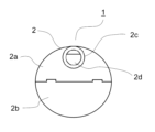
- FIG. 4 is a bottom view showing the vibrator of the hearing device according to the embodiment of the present invention
- FIG. FIG. 4 is a rear view showing the vibrator of the hearing device according to the embodiment of the present invention
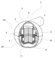
- 4 is a diagram showing the internal structure of the transducer of the hearing device according to the embodiment of the present invention
- FIG. 1 is an exploded perspective view of a transducer of a hearing device according to an embodiment of the present invention
- FIG. 3 is a side view of the damper of the transducer of the hearing device according to the embodiment of the present invention
- 4 is a side view showing a state in which cables are connected to transducers of the hearing device according to the embodiment of the present invention
- FIG. FIG. 4 is a perspective view showing another example of the shape of the transducer of the hearing device according to the embodiment of the present invention
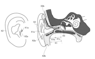
- FIG. 9 is a perspective view showing still another example of the shape of the transducer of the hearing device according to the embodiment of the present invention. It is an anatomical drawing of an ear.
- 4 is a graph showing an example of measured data showing the effect of cartilage conduction. It is a figure which shows the usage condition of a hearing device.
- FIG. 1 is a perspective view showing a transducer 1 of a hearing device according to an embodiment of the invention. 2 is a side view showing the vibrator 1, FIG. 3 is a bottom view showing the vibrator 1, and FIG. 4 is a rear view showing the vibrator 1. FIG.
- the case 2 of the vibrator 1 is composed of an upper case 2a and a lower case 2b.
- the upper case 2a and the lower case 2b are fixed to each other with an adhesive or the like.
- a projecting portion 2c is formed on the upper case 2a.
- the case 2 is made of resin (for example, ABS resin) or the like.
- FIG. 8 is a side view showing a state in which the cable 12 is connected to the vibrator 1.
- the surface of the case 2 excluding the projecting portion 2c is a curved surface.
- the portion of the case 2 excluding the projecting portion 2c has a spherical or nearly spherical shape.
- Spherical includes not only a perfectly spherical shape but also a substantially spherical shape within a certain error range.
- the vertical interval W2 between the projecting portions 2c is less than or equal to half the interval W3 from the lower end to the upper end of the upper case 2a.
- the projecting portion 2c extends in a tangential direction of the upper case 2, for example.
- FIG. 5 is a diagram (partial cross-sectional view with part of the transducer 1 cut away) showing the internal structure of the transducer 1 of the hearing device according to the embodiment of the present invention.
- FIG. 6 is an exploded perspective view of the transducer 1 of the hearing device according to the embodiment of the invention.
- a coil bobbin 4 , a coil 5 , magnets (first magnet 6 and second magnet 8 ), top plate 7 , frame 9 , damper 10 , yoke 11 and substrate 3 are housed in case 2 .
- a coil 5 is wound around the outside of the coil bobbin 4 .
- the coil bobbin 4 is long in the vertical direction, and the upper end of the coil bobbin 4 is in contact with the inner surface of the case 2 (upper case 2a).
- An electrical signal (such as an audio signal) is input to the coil 5 .
- the coil bobbin 4 is made of kraft paper or the like, and the coil 5 is made of copper or the like.
- the substrate 3 is attached to the inner surface of the case 2 (upper case 2a).
- a cable 12 (FIG. 8) is connected to the substrate 3, and a terminal side (not shown) of the coil 5 or wiring (not shown) connected to the coil 5 is connected.
- the cable 12 can be easily connected to the board 3. Further, the coil bobbin 4 is formed vertically so that its upper end abuts against the substrate 3 and the inner surface of the case 2 (upper case 2a). Wiring (not shown) can be easily connected to the substrate 3 .
- the magnets include a first magnet 6 and a second magnet 8 .
- Neodymium magnets for example, are used for the first magnet 6 and the second magnet 8 .
- the top plate 7 is arranged inside the coil bobbin 4 .
- a first magnet 6 is arranged on top plate 7 .
- a second magnet 8 is arranged under the top plate 7 .
- Iron SPCC or the like is used for the top plate 7, for example.
- the yoke 11 is open on the upper end side and has a bottom portion and a peripheral wall portion.
- the shape of the bottom inside the yoke 11 corresponds to the shape of the bottom end of the second magnet 8 so that the bottom end of the second magnet 8 is fixed inside the yoke 11 . Therefore, positioning of the second magnet 8 is facilitated.
- the yoke 11 is made of a soft magnetic material (such as SPCC).
- At least part of the coil bobbin 4 is arranged inside the yoke 11 .
- the outer edge of the damper 10 is fixed to the case 2 and sandwiched between the upper case 2a and the lower case 2b. That is, the outer edge of the damper 10 is sandwiched between the upper case 2a and the lower case 2b. A lower surface of the inner edge portion of the damper 10 is in contact with the upper end of the peripheral wall portion of the yoke 11 .
- the damper 10 is made of stainless steel, for example. As shown in FIG. 7, the damper 10 is formed with a through hole 10a penetrating vertically. A plurality of notches 10b are formed in the periphery of the damper 10. As shown in FIG.
- a plurality of concave portions 2e are formed in the upper case 2a, and a plurality of convex portions 2f are formed in the lower case 2b.
- the concave portion 2e and the convex portion 2f are combined at the notch 10b.
- the damper 10 is attached between the upper case 2a and the lower case 2b.
- the frame 9 fixes the damper 10 to the yoke 11. Specifically, the frame 9 is crimped and fixed to the damper 10 and the yoke 11 so as to contact the upper surface of the inner edge of the damper 10 and the inner surface of the peripheral wall of the yoke 11 .
- the frame 9 is made of a soft magnetic material (such as SPCC [steel plate cold commercial]).
- the damper 10 is fixed to the yoke 11 with an adhesive or the like (without using the frame 9), the fixing between the damper 10 and the yoke 11 is unstable. However, since the damper 10 is fixed to the yoke 11 using the frame 9, the damper 10 and the yoke 11 are easily fixed. That is, fixing the damper 10 and the yoke 11 using such a frame 9 is suitable for mass production.
- the damper 10 supports the yoke 11 by fixing the damper 10 to the yoke 11 by the frame 9 .
- the yoke 11 is suspended inside the case 2 by the damper 10 and the frame 9 . That is, the yoke 11 is separated from the inner surface of the case 2 .
- the yoke 11 is separated from the inner surface of the case 2, and such problems can be avoided.
- At least a part of the peripheral wall portions of the frame 9 and the yoke 11 faces the coil 5 .
- a soft magnetic material such as SPCC
- the case has a hole, sound leaks through the hole when the vibrator vibrates. If it is desirable to prevent sound leakage, it is conceivable to seal the case.
- case 2 may be sealed.
- a closing member (not shown) may be used to close the wiring hole 2d.
- the case is sealed and the diaphragm (damper, etc.) inside the case is formed in a shape without holes, it is difficult for vibration to occur. Especially if the case is small, the diaphragm will be difficult to move due to the air pressure inside the case.
- the space inside the case is divided into an upper space and a lower space by the diaphragm. For example, even if the diaphragm tries to move downward, the air in the lower space cannot move to the upper space. Therefore, the diaphragm cannot vibrate, or the amplitude of vibration of the diaphragm becomes small.
- the damper 10 is formed with a through hole 10a.
- the air above the damper 10 can move to the lower side of the damper 10 through the through holes 10a.
- the air below the damper 10 can move to the upper side of the damper 10 through the through holes 10a. Air movement within case 2 is unrestricted.
- the damper 10 can vibrate greatly not only when the case 2 is not sealed but also when the inside of the case 2 is a closed space. Therefore, even if the case 2 is small and sealed, the damper 10 can vibrate greatly.
- the damper 10 can vibrate greatly, so the case 2 can vibrate sufficiently. Therefore, sufficient vibration can be transmitted to the user of the vibrator 1 .
- the vibration of the damper or yoke causes the case to vibrate.
- the vibration is transmitted to the user and the user perceives the sound.
- the case vibrates the air around the case vibrates and air conduction sound is generated.
- the surface area is small and air-conducted noise can be suppressed. Therefore, it is possible to suppress leakage of air-conducted sound to the surroundings of the user while transmitting vibration to the user.
- the damper 10 may be made of Liquid Metal.
- the damper 10 may be damaged due to repeated vibrations. Although Liquidmetal is a metal, it has elasticity and is resistant to fatigue damage. When the damper 10 is made of Liquid Metal, the damper 10 can be used for a long time.
- the damper 10 is arranged in the center of the case 2 in the vertical direction.
- the case 2 can be made spherical or nearly spherical without increasing the size of the case 2. - ⁇ Note that the "center" includes not only the perfect center but also the substantial center within a certain error range.
- the shape of the case may be any other shape, and may not be spherical or nearly spherical like case 2 .
- FIG. 9 is a perspective view showing another shape example of the vibrator
- FIG. 10 is a perspective view showing still another shape example of the vibrator.
- Case 13 instead of Case 13 (FIG. 9) or Case 14 (FIG. 10) may be used instead of Case 2, instead of Case 2, the shapes of various parts such as dampers or yokes are appropriately changed so as to correspond to the shape of the case.
- the oscillator 1 may be used as a cartilage conduction oscillator. Therefore, the hearing device of the present invention preferably has the above transducer 1 as a cartilage conduction transducer for transmitting sound signals to the ear cartilage.
- FIG. 11 is an anatomical drawing of the ear.
- the above-described cartilage conduction makes it possible to hear sound by vibrating the tragus X2a and the auricular cartilage X2b, which are lighter. Very little drive energy is required.
- FIG. 12 is a graph showing an example of measured data showing the effect of cartilage conduction.
- This graph shows the inside of the external auditory canal 1 cm behind the entrance of the external auditory canal when the outer wall surface of the vibrator vibrating by the cartilage conduction vibration source is brought into contact with at least a part of the ear cartilage around the entrance of the external auditory canal without contacting the helix. It shows sound pressure in relation to frequency.
- the vertical axis of this graph is the sound pressure (dBSPL), and the horizontal axis is the frequency (Hz) on a logarithmic scale.
- this graph shows the effect of the contact pressure between the outer wall surface of the vibrator and the ear cartilage around the entrance of the ear canal on the sound pressure in the ear canal.
- the solid line represents the sound pressure at a contact pressure of 10 weight grams
- the dashed line represents the sound pressure at a contact pressure of 250 weight grams
- the external auditory canal is closed by further increasing the contact pressure.
- the two-dot chain line shows the sound pressure in the state where the contact pressure is 500 weight grams.
- the sound pressure increases from no contact to contact with a contact pressure of 10 grams force, further increases with an increase in contact pressure to 250 force grams, and from this state further increases the contact pressure to 500 force grams. This further increases the sound pressure.
- the distance of 1 cm from the entrance of the ear canal is higher than in the non-contact state. It can be seen that the sound pressure in the ear canal has increased by at least 10 dB in the main frequency band of sound (500 Hz to 2300 Hz).
- the necessary sound pressure can be obtained by transmitting the vibration of the cartilage conduction vibration source to the ear cartilage through contact, even without the mechanism for generating air-conducted sound (for example, the diaphragm of normal earphones).
- the vibrating body since the vibrating body is brought into contact with the ear cartilage around the entrance of the ear canal, it is possible to hear the sound from the vibrator without blocking the ear canal while keeping the ear canal open, and at the same time hearing the sound of the external world. It can be seen that comfortable wearing without a feeling of blockage is possible.
- the external auditory canal is closed by bringing the outer wall surface of the vibrating body into contact with at least a part of the ear cartilage more strongly (in the actual measurement of this figure, the outer wall surface of the vibrating body is pressed from the outside of the tragus).
- the ear canal is closed by bending the tragus)
- the sound pressure in the ear canal 1 cm behind the entrance of the ear canal is higher than that in the non-contact state in the main frequency band of sound (300 Hz to 1800 Hz).
- This indicates a large sound pressure enhancement effect due to the addition of the external auditory canal closing effect (compare the non-contact state shown by the solid line and the external auditory canal closed state shown by the two-dot chain line).
- the measurements in this graph are in a state where the output of the cartilage conduction vibration source is not changed.
- the measurement in this graph is a state in which the outer wall surface of the vibrating body is in contact with the outside of the tragus. I'm going with
- the measurement in the state where the ear canal is closed in this graph is performed by creating a state in which the ear canal is closed by pressing the tragus more strongly from the outside so that the tragus folds back as described above. .
- this graph is just an example, and there are individual differences if you look closely.
- this graph is measured in a state in which the outer wall surface of the vibrating body contacts only the outside of the tragus with a small area.
- the increase in sound pressure due to contact also depends on the contact area with the ear cartilage.
- the increase in sound pressure is further increased by contacting a wider ear cartilage portion.
- this graph shows that when the external auditory canal is closed, the contact pressure is increased by pressing the tragus from the outside to fold back the tragus. Similar results are obtained when the
- FIG. 13 is a diagram showing how the hearing device is used.
- the hearing device shown in FIG. 1 is used as, for example, a headphone such as a smartphone or a portable music player, a hearing aid, or a sound collector, and includes the aforementioned vibrator 1 as a cartilage vibrator.
- the invention disclosed in this specification can be used, for example, in smartphones, headphones such as portable music players, hearing aids, or sound collectors.
Landscapes
- Physics & Mathematics (AREA)
- Engineering & Computer Science (AREA)
- Acoustics & Sound (AREA)
- Signal Processing (AREA)
- Health & Medical Sciences (AREA)
- General Health & Medical Sciences (AREA)
- Otolaryngology (AREA)
- Neurosurgery (AREA)
- Electromagnetism (AREA)
- Details Of Audible-Bandwidth Transducers (AREA)
- Headphones And Earphones (AREA)
- Audible-Bandwidth Dynamoelectric Transducers Other Than Pickups (AREA)
Priority Applications (3)
| Application Number | Priority Date | Filing Date | Title |
|---|---|---|---|
| US18/288,976 US12464290B2 (en) | 2021-10-01 | 2022-09-14 | Vibrator and hearing device |
| JP2023551290A JP7586553B2 (ja) | 2021-10-01 | 2022-09-14 | 振動子及び聴取装置 |
| CN202280031848.3A CN117296336B (zh) | 2021-10-01 | 2022-09-14 | 振子以及听音装置 |
Applications Claiming Priority (2)
| Application Number | Priority Date | Filing Date | Title |
|---|---|---|---|
| JP2021-162849 | 2021-10-01 | ||
| JP2021162849 | 2021-10-01 |
Publications (1)
| Publication Number | Publication Date |
|---|---|
| WO2023053958A1 true WO2023053958A1 (ja) | 2023-04-06 |
Family
ID=85782425
Family Applications (1)
| Application Number | Title | Priority Date | Filing Date |
|---|---|---|---|
| PCT/JP2022/034333 Ceased WO2023053958A1 (ja) | 2021-10-01 | 2022-09-14 | 振動子及び聴取装置 |
Country Status (3)
| Country | Link |
|---|---|
| US (1) | US12464290B2 (https=) |
| JP (1) | JP7586553B2 (https=) |
| WO (1) | WO2023053958A1 (https=) |
Cited By (1)
| Publication number | Priority date | Publication date | Assignee | Title |
|---|---|---|---|---|
| US12464290B2 (en) | 2021-10-01 | 2025-11-04 | Finewell Co., Ltd. | Vibrator and hearing device |
Citations (3)
| Publication number | Priority date | Publication date | Assignee | Title |
|---|---|---|---|---|
| WO2004006620A1 (ja) * | 2002-07-04 | 2004-01-15 | Nec Tokin Corporation | 電気音響変換器 |
| JP2006203709A (ja) * | 2005-01-24 | 2006-08-03 | Citizen Electronics Co Ltd | 振動体 |
| WO2009133986A1 (en) * | 2008-05-01 | 2009-11-05 | Yea Il Electronics Co., Ltd. | Sensory signal output apparatus |
Family Cites Families (12)
| Publication number | Priority date | Publication date | Assignee | Title |
|---|---|---|---|---|
| JP3680562B2 (ja) * | 1997-10-30 | 2005-08-10 | 松下電器産業株式会社 | 電気−機械−音響変換器及びその製造法 |
| JP3771831B2 (ja) | 2001-11-01 | 2006-04-26 | インターナショナル・ビジネス・マシーンズ・コーポレーション | デジタル・コンテンツに付加されるアノテーション情報を共有するためのコンピュータ・システムおよびプログラム |
| DE102006017016A1 (de) * | 2005-04-19 | 2006-11-09 | Citizen Electronics Co., Ltd., Fujiyoshida | Elektromagnetischer Erreger |
| KR101047548B1 (ko) * | 2009-06-24 | 2011-07-07 | 주식회사 비에스이 | 다기능 마이크로 스피커 |
| JP6256139B2 (ja) | 2014-03-25 | 2018-01-10 | ゴールデンダンス株式会社 | 骨伝導デバイス |
| JP6238302B2 (ja) | 2014-12-17 | 2017-11-29 | 国立大学法人 名古屋工業大学 | 骨伝導デバイス |
| JP6601973B2 (ja) | 2017-01-17 | 2019-11-06 | コスモギア株式会社 | 骨伝導振動子およびその製造方法 |
| CN209805645U (zh) | 2019-06-24 | 2019-12-17 | 歌尔科技有限公司 | 一种激励器及电子产品 |
| JP6618230B1 (ja) | 2019-09-18 | 2019-12-11 | ゴールデンダンス株式会社 | ピックアップセンサ及び骨伝導スピーカ |
| CN216313372U (zh) | 2021-09-10 | 2022-04-15 | 苏州索迩电子技术有限公司 | 一种振动装置、骨传导耳机、可穿戴设备及智能硬件设备 |
| WO2023053958A1 (ja) | 2021-10-01 | 2023-04-06 | 株式会社ファインウェル | 振動子及び聴取装置 |
| CN114071334A (zh) | 2021-11-30 | 2022-02-18 | 深圳市明悦达电声科技有限公司 | 一种复合式扬声器及发声装置 |
-
2022
- 2022-09-14 WO PCT/JP2022/034333 patent/WO2023053958A1/ja not_active Ceased
- 2022-09-14 US US18/288,976 patent/US12464290B2/en active Active
- 2022-09-14 JP JP2023551290A patent/JP7586553B2/ja active Active
Patent Citations (3)
| Publication number | Priority date | Publication date | Assignee | Title |
|---|---|---|---|---|
| WO2004006620A1 (ja) * | 2002-07-04 | 2004-01-15 | Nec Tokin Corporation | 電気音響変換器 |
| JP2006203709A (ja) * | 2005-01-24 | 2006-08-03 | Citizen Electronics Co Ltd | 振動体 |
| WO2009133986A1 (en) * | 2008-05-01 | 2009-11-05 | Yea Il Electronics Co., Ltd. | Sensory signal output apparatus |
Cited By (1)
| Publication number | Priority date | Publication date | Assignee | Title |
|---|---|---|---|---|
| US12464290B2 (en) | 2021-10-01 | 2025-11-04 | Finewell Co., Ltd. | Vibrator and hearing device |
Also Published As
| Publication number | Publication date |
|---|---|
| JPWO2023053958A1 (https=) | 2023-04-06 |
| JP7586553B2 (ja) | 2024-11-19 |
| US12464290B2 (en) | 2025-11-04 |
| CN117296336A (zh) | 2023-12-26 |
| US20240223957A1 (en) | 2024-07-04 |
Similar Documents
| Publication | Publication Date | Title |
|---|---|---|
| KR101484650B1 (ko) | 골전도 스피커 모듈 및 골전도 스피커 모듈이 구비된 골전도 이어폰 | |
| JP6515392B2 (ja) | 音声振動発生素子 | |
| CN114615602A (zh) | 一种骨传导扬声器 | |
| KR100934273B1 (ko) | 진동형 이어폰 | |
| JPWO2015198683A1 (ja) | 骨伝導スピーカ | |
| KR101092958B1 (ko) | 이어셋 | |
| KR101537380B1 (ko) | 골전도 스피커 모듈이 구비된 골전도 이어폰 | |
| KR20050106482A (ko) | 골전도 장치 | |
| CN111955017B (zh) | 电声换能器和声学装置 | |
| WO2021063113A1 (zh) | 骨传导扬声器、骨传导耳机及骨传导助听器 | |
| JP2010087810A (ja) | 耳穴式骨伝導レシーバ | |
| CN101690261A (zh) | 用于产生身体可感觉到的振动的小型声音接收器 | |
| WO2021063112A1 (zh) | 骨传导扬声器、骨传导耳机及骨传导助听器 | |
| CN111988696B (zh) | 耳机 | |
| WO2023097740A1 (zh) | 一种复合式扬声器及发声装置 | |
| JP2008270879A (ja) | 受話装置 | |
| JP2011119913A (ja) | ハイブリッド型スピーカーユニットおよびハイブリッド型スピーカー | |
| JP3045032B2 (ja) | ヘッドホン | |
| JP7586553B2 (ja) | 振動子及び聴取装置 | |
| CN116349248B (zh) | 一种降漏音装置及声学输出装置 | |
| JP6006686B2 (ja) | スピーカ装置 | |
| CN209267765U (zh) | 一种骨传导扬声器以及骨传导发声装置 | |
| CN117296336B (zh) | 振子以及听音装置 | |
| WO2016181431A1 (ja) | 連通部付き密閉イヤホン | |
| TW202135538A (zh) | 揚聲器結構 |
Legal Events
| Date | Code | Title | Description |
|---|---|---|---|
| 121 | Ep: the epo has been informed by wipo that ep was designated in this application |
Ref document number: 22875829 Country of ref document: EP Kind code of ref document: A1 |
|
| WWE | Wipo information: entry into national phase |
Ref document number: 202280031848.3 Country of ref document: CN Ref document number: 18288976 Country of ref document: US Ref document number: 2023551290 Country of ref document: JP |
|
| NENP | Non-entry into the national phase |
Ref country code: DE |
|
| 122 | Ep: pct application non-entry in european phase |
Ref document number: 22875829 Country of ref document: EP Kind code of ref document: A1 |
|
| WWG | Wipo information: grant in national office |
Ref document number: 18288976 Country of ref document: US |