WO2023053922A1 - 助手席用エアバッグ装置 - Google Patents
助手席用エアバッグ装置 Download PDFInfo
- Publication number
- WO2023053922A1 WO2023053922A1 PCT/JP2022/034083 JP2022034083W WO2023053922A1 WO 2023053922 A1 WO2023053922 A1 WO 2023053922A1 JP 2022034083 W JP2022034083 W JP 2022034083W WO 2023053922 A1 WO2023053922 A1 WO 2023053922A1
- Authority
- WO
- WIPO (PCT)
- Prior art keywords
- chamber
- sub
- main chamber
- airbag device
- airbag
- Prior art date
Links
- 238000005192 partition Methods 0.000 claims description 9
- 239000004744 fabric Substances 0.000 claims description 6
- 238000007599 discharging Methods 0.000 claims description 2
- 230000000452 restraining effect Effects 0.000 abstract description 2
- 238000009958 sewing Methods 0.000 description 8
- 230000007423 decrease Effects 0.000 description 4
- 238000004519 manufacturing process Methods 0.000 description 2
- 230000003247 decreasing effect Effects 0.000 description 1
- 238000010586 diagram Methods 0.000 description 1
- 230000001788 irregular Effects 0.000 description 1
- 238000000465 moulding Methods 0.000 description 1
- 239000011347 resin Substances 0.000 description 1
- 229920005989 resin Polymers 0.000 description 1
- 230000008961 swelling Effects 0.000 description 1
Images


Classifications
-
- B—PERFORMING OPERATIONS; TRANSPORTING
- B60—VEHICLES IN GENERAL
- B60R—VEHICLES, VEHICLE FITTINGS, OR VEHICLE PARTS, NOT OTHERWISE PROVIDED FOR
- B60R21/00—Arrangements or fittings on vehicles for protecting or preventing injuries to occupants or pedestrians in case of accidents or other traffic risks
- B60R21/02—Occupant safety arrangements or fittings, e.g. crash pads
- B60R21/16—Inflatable occupant restraints or confinements designed to inflate upon impact or impending impact, e.g. air bags
- B60R21/20—Arrangements for storing inflatable members in their non-use or deflated condition; Arrangement or mounting of air bag modules or components
- B60R21/205—Arrangements for storing inflatable members in their non-use or deflated condition; Arrangement or mounting of air bag modules or components in dashboards
-
- B—PERFORMING OPERATIONS; TRANSPORTING
- B60—VEHICLES IN GENERAL
- B60R—VEHICLES, VEHICLE FITTINGS, OR VEHICLE PARTS, NOT OTHERWISE PROVIDED FOR
- B60R21/00—Arrangements or fittings on vehicles for protecting or preventing injuries to occupants or pedestrians in case of accidents or other traffic risks
- B60R21/02—Occupant safety arrangements or fittings, e.g. crash pads
- B60R21/16—Inflatable occupant restraints or confinements designed to inflate upon impact or impending impact, e.g. air bags
- B60R21/23—Inflatable members
- B60R21/231—Inflatable members characterised by their shape, construction or spatial configuration
- B60R21/233—Inflatable members characterised by their shape, construction or spatial configuration comprising a plurality of individual compartments; comprising two or more bag-like members, one within the other
Definitions
- the present invention relates to a passenger airbag device that protects an occupant sitting in the passenger seat of a vehicle.
- Airbags include, for example, so-called driver airbags that inflate from near the center of the steering wheel of an automobile to protect the driver, and passenger airbags that inflate from the instrument panel to protect the occupants in the front passenger seat. , and curtain airbags that deploy downward inside the vehicle window to protect occupants in the event of a vehicle lateral impact, rollover, or rollover accident.
- driver airbags that inflate from near the center of the steering wheel of an automobile to protect the driver
- passenger airbags that inflate from the instrument panel to protect the occupants in the front passenger seat.
- curtain airbags that deploy downward inside the vehicle window to protect occupants in the event of a vehicle lateral impact, rollover, or rollover accident.
- There are various forms such as a side airbag that deploys.
- the present invention relates to an airbag device for passenger's seat.
- the occupant may enter the deployed airbag at an irregular position and angle, and the occupant's head may not be properly protected. be.
- the head of the occupant in the front passenger seat comes into contact with a position that is displaced from the center of the airbag.
- a phenomenon called "bottoming out” will occur. That is, there is a possibility that a situation may occur in which it is difficult to properly restrain the head of the occupant.
- the present invention has been made in view of the above circumstances, and an object of the present invention is to provide an airbag device capable of appropriately restraining the head of an occupant sitting in the front passenger seat of a vehicle.
- the present invention provides an airbag device that is housed in an instrument panel of a vehicle and protects an occupant in a front passenger seat, comprising: an inflator that generates inflation gas; gas released from the inflator; and an airbag that inflates and deploys toward the occupant side.
- the airbag has a main chamber that communicates with the inflator and is located in a region including the front of the normally seated occupant when deployed, and a sub-chamber that is connected to the side of the main chamber.
- An inner vent through which gas flows is formed at the boundary between the main chamber and the sub-chamber.
- a check valve capable of opening and closing the inner vent is provided.
- the “instrument panel” is the part located in front of the front seats of a vehicle and located below the windshield (windshield), and is generally molded from resin and is called the dashboard.
- the airbag device can be accommodated inside other structural parts in the cabin as well as inside the instrument panel.
- side is a concept that includes one or both of the left and right sides of the main chamber.
- the "boundary part” is the part where the main chamber and the sub-chamber are in contact with each other as a region, and not only when the entire side surfaces of the chambers are connected by sewing etc. at the boundary part, but also includes at least the periphery of the inner vent. It also includes the state of connecting certain regions.
- front means the front of the vehicle (in the direction of travel)
- rear means the rear of the vehicle (opposite to the direction of travel)
- right means The right side as seen in the direction of travel, "left” as viewed in the direction of travel, and the "vehicle width direction” as the left-right direction.
- the inflation gas generated from the inflator flows into the main chamber of the airbag and then passes through the inner vent to reach the sub-chamber, whereupon the airbag is inflated.
- the gas pressure in the sub-chamber rises and the check valve closes the inner vent to maintain the pressure in the sub-chamber. It is possible to appropriately restrain the occupant who has entered the sub-chamber.
- the sub-chamber can be provided on the center side (driver's seat side) of the vehicle with respect to the main chamber. As a result, it is possible to reliably avoid a situation in which an occupant sitting in the front passenger seat comes into contact with the center console, instrument panel, driver, etc. due to the impact of the collision.
- the check valve can be composed of a flexible cloth-like member arranged to cover the inner vent.
- the cloth-like member the same fabric as that forming the airbag can be used.
- the volume of the sub-chamber smaller than the volume of the main chamber. This is because the occupant is reliably restrained by the main chamber having a large volume in the event of a head-on collision or the like.
- the main chamber and the sub-chamber can be molded as independent and separate bags.
- the inner vent is constituted by an opening formed in both chambers at a portion where the main chamber and the sub-chamber are in contact with each other.
- the main chamber and the sub-chamber can be formed, and the inner vent can be formed in the partition panel.
- the sub-chamber can be formed by a base fabric whose perimeter is connected to the side surface of the main chamber. At this time, the inner vent is formed on the side surface of the main chamber.
- the main chamber preferably has a vent hole for exhausting gas to the outside.
- the internal pressure of the sub-chamber rises when an occupant touches the sub-chamber, but the internal pressure of the main chamber gradually decreases. will decrease. For this reason, the sub-chamber, whose internal pressure is maintained, tends to move toward or tilt toward the main chamber, which has become flexible due to the exhaust of the gas. As a result, the occupant's head can be reliably restrained without the sub-chamber escaping outward (to the side opposite to the main chamber).
- the sub-chamber can be configured to have a substantially triangular shape when the deployed state is observed from above.
- substantially triangular is not limited to a strict triangle, but also includes a shape having three sides, with slightly rounded or slightly chamfered corners.
- the triangular shape has a first side facing the occupant, a second side positioned at the boundary with the main chamber, and a third side forming a side portion of the airbag. be able to.
- the force received by the sub-chamber when an occupant enters the plane corresponding to the first side of the sub-chamber (occupant side) is can be absorbed by
- the length of the first side can be formed to be shorter than the length of the second side.
- the lateral width of the sub-chamber when deployed is shorter than the longitudinal depth thereof.
- the surface forming the first side of the sub-chamber and the surface of the main chamber facing the occupant can be configured to form substantially the same surface.
- the front end of the sub-chamber can be configured to be located rearward from the front end of the main chamber.
- the sub-chamber may be configured to be connected only to one side of the main chamber.
- the sub-chamber may be configured to be connected to a side portion of the main chamber on the vehicle interior side.
- the sub-chamber can be connected to the side of the main chamber on the exterior side (window side).
- subchambers can be provided on both left and right sides of the main chamber.
- the occupant's head can be appropriately restrained regardless of the direction (offset angle) in which the vehicle collides.
- FIG. 1 is a side view showing the deployed state of an airbag according to the present invention.
- FIG. 2 shows the deployed state of the airbag according to the first embodiment of the present invention, and corresponds to a cross section taken along the A1-A1 direction in FIG.
- FIG. 3 is a perspective view showing an enlarged main part of FIG. 2.
- FIG. 4 schematically shows the deployed state of the airbag according to the present invention, and is an explanatory view showing the dimensions (shape, dimensional ratio, etc.) of the airbag.
- FIG. 5 is a cross-sectional view (overhead view) showing the deployed state of the airbag according to the first embodiment of the present invention, showing the state in which the occupant has entered the sub-chamber.
- FIG. 1 is a side view showing the deployed state of an airbag according to the present invention.
- FIG. 2 shows the deployed state of the airbag according to the first embodiment of the present invention, and corresponds to a cross section taken along the A1-A1 direction in FIG.
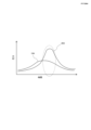
- FIG. 6 is a graph showing pressure fluctuations of an airbag according to the present invention.
- FIG. 7 shows the deployed state of the airbag according to the second embodiment of the present invention, and corresponds to the cross section taken along the A1-A1 direction in FIG.
- FIG. 8 shows the deployed state of the airbag according to the third embodiment of the present invention, and corresponds to the cross section along the A1-A1 direction in FIG.
- FIG. 9 shows the deployed state of the airbag according to the fourth embodiment of the present invention, and corresponds to the cross section along the A1-A1 direction in FIG.
- FIG. 10 shows the deployed state of the airbag according to the fifth embodiment of the present invention, and corresponds to the cross section along the A1-A1 direction in FIG.
- FIG. 1 is a side view showing an unfolded state of an airbag 14 of a passenger-side airbag device according to the first embodiment of the present invention.
- FIG. 2 is a cross-sectional view in the direction of A1-A1 in FIG. 1, showing the deployed state of the airbag 14.
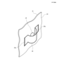
- FIG. 3 is a perspective view showing an enlarged main portion (around the inner vent) of FIG. 2 .
- the airbag device is housed in an instrument panel 10 of a vehicle and protects an occupant P in a front passenger seat.
- An airbag 14 that inflates and deploys toward the occupant P side is provided.
- the airbag 14 is connected to a main chamber 18 that communicates with the inflator 12 and deploys in front of the normally seated occupant P, and a side portion (right side portion in this embodiment) of the main chamber 18 on the vehicle center side. and a subchamber 20 .
- An inner vent 24 through which gas flows is formed at the boundary between the main chamber 18 and the sub-chamber 20, and a check valve 26 capable of opening and closing the inner vent 24 is provided.
- the main chamber 18 and the sub-chamber 20 are connected by sewing at the boundary.
- the sewing range includes at least the periphery of the inner vent 24, but other regions can also be sewn.
- vent holes 22 are formed in the left and right sides of the main chamber 18 for discharging the gas inside the main chamber 18 .
- the main chamber 18 and the subchamber 20 are molded as independent and separate bags.
- the inner vent 24 is formed by openings formed in both the main chamber 18 and the sub-chamber 20 at the contact portion.
- the check valve 26 is a flexible cloth-like member arranged to cover the inner vent 24, and can be made of the same fabric that forms the airbag 14, for example.
- An end portion 26a of the check valve 26 is connected to the inner surface of the subchamber 20 by sewing.
- the check valve 26 becomes convex toward the inside of the sub-chamber 20 by the gas flowing from the main chamber 18 to the sub-chamber 20 side, so that the inner vent 24 is opened.
- the check valve 26 is in close contact with the inner surface of the sub-chamber 20 to close the inner vent 24 .
- the volume of the subchamber 20 is set smaller than that of the main chamber 18 .
- the volume of subchamber 20 can be 10-20% of the volume of main chamber 18 .
- FIG. 4 schematically shows the deployment state of the airbag according to the present invention, and is an explanatory diagram showing the dimensions (shape, dimensional ratio, etc.) of the airbag 14. As shown in FIG.
- the sub-chamber 20 is configured to have a substantially triangular shape when the deployed state is observed from above.
- substantially triangular is not limited to a strictly triangular shape, but also includes a shape having three sides, with slightly rounded or slightly chamfered corners.
- the triangular shape of the sub-chamber 20 when viewed from the top includes a first side a1 facing the occupant, a second side a2 located at the boundary with the main chamber 18, and an airbag 14. and a third side a3 forming part of the side portion (right side portion) on the vehicle center side.
- the main chamber 18 can absorb the force that the sub-chamber 20 receives.
- the length L1 of the first side a1 is shorter than the length L2 of the second side a2, and the lateral width (L1) of the subchamber 20 when deployed is shorter than the longitudinal depth.
- the surface forming the first side a1 of the sub-chamber 20 and the surface A1 of the main chamber 18 facing the occupant are configured to form substantially the same surface.
- front end 20F of the subchamber 20 is configured to be located rearward from the front end 18F of the main chamber 18.
- FIG. 5 is a cross-sectional view (overhead view) showing the unfolded state of the passenger airbag 14 according to the first embodiment of the present invention, showing the state in which the occupant P has entered the sub-chamber 20.
- FIG. 6 is a graph showing variations in internal pressure of the main chamber 18 and the sub-chamber 20, where 18A represents the internal pressure of the main chamber 18 and 20A represents the internal pressure of the sub-chamber 20. As shown in FIG.
- the inflation gas generated from the inflator 12 flows into the main chamber 18 of the airbag 14 and then into the sub-chamber 20 via the inner vent 24 .
- the check valve 26 provided inside the sub-chamber 20 is swollen toward the sub-chamber 20 by the pressure of the gas flowing from the main chamber 18 , and the gas flows into the sub-chamber 20 from the inner vent 24 . It will flow in quickly (see Figure 2).
- the sub-chamber 20 As described above, when the occupant P contacts the sub-chamber 20, the internal pressure of the sub-chamber 20 increases, but the internal pressure of the main chamber 18 gradually decreases. Therefore, the sub-chamber 20 with its internal pressure maintained tends to move or tilt toward the main chamber 18 which has become flexible due to the exhaust of the gas. As a result, the head of the occupant P can be reliably restrained without the sub-chamber 20 escaping to the outside (to the side opposite to the main chamber 18).
- FIG. 7 shows the deployed state of the airbag 114 according to the second embodiment of the present invention, and corresponds to the cross section along the A1-A1 direction in FIG.
- the main chamber 18 and the sub-chamber 20 constituting the airbag 14 are constructed as independent and separate bags.
- a main chamber 118 and a sub-chamber 120 are formed by providing a partition panel 130 inside the airbag (114).
- the partition panel 130 is provided with an inner vent 124 and a check valve 126 .
- the functions of the inner vent 124 and the check valve 126 are the same as in the first embodiment.
- Front and rear ends 130a of the partition panel 130 are connected to the inner surface of the airbag by sewing. Also, the end portion 126a of the check valve 126 is connected to the surface of the partition panel 130 on the sub-chamber 120 side by sewing.
- Vent holes 122 are formed at two locations on the outer surface of the main chamber 118 in the same manner as in the first embodiment.
- the partition panel 130 is provided inside the single airbag, the structure is simpler than in the first embodiment, and simplification of the manufacturing process is expected.
- FIG. 8 shows the deployed state of the airbag 214 according to the third embodiment of the present invention, and corresponds to the cross section along the A1-A1 direction in FIG.
- the main chamber 18 and the sub-chamber 20 constituting the airbag 14 are constructed as independent and separate bags.
- a sub-chamber 220 is formed by stitching a base fabric to the sides of 218 . That is, the sub-chamber 220 is formed by sewing the perimeter 220a of the base fabric for the sub-chamber to the side surface of the main chamber 218 .
- An inner vent 224 communicating with the sub-chamber 220 is formed in the main chamber 218 , and a check valve 226 is provided so as to cover the inner vent 224 .
- the basic functions of the inner vent 224 and the check valve 226 are the same as in the first embodiment.
- vent holes 222 are formed at two locations on the outer surface of the main chamber 218, as in the first embodiment.
- FIG. 9 shows the unfolded state of the airbag 314 according to the fourth embodiment of the invention, and corresponds to the cross section along the A1-A1 direction in FIG.
- the upper surface shape of the subchambers (20, 120, 220) was substantially triangular, but the subchamber 320 employed in this embodiment is substantially rectangular. It's becoming Configurations other than the shape of the sub-chamber are the same as those of the first embodiment, and redundant description will be omitted.
- Vent holes 322 are formed at two locations on the outer surface of the main chamber 318 in the same manner as in the first embodiment.
- the subchambers 20, 120, 220, 320 employed in the first to fourth embodiments described above are connected only to one side of the main chambers 18, 118, 218, 318, when the subchambers 20 , 120 , 220 , 320 are preferably connected to side portions of main chambers 18 , 118 , 218 , 318 on the interior side of the vehicle (vehicle center side: far side). This is because curtain airbags are usually deployed on the outside of the vehicle (vehicle door side: near side), so there is a high need for head protection on the inside of the vehicle where there is no curtain airbag.
- FIG. 10 shows the unfolded state of the airbag 414 according to the fifth embodiment of the invention, and corresponds to the cross section along the A1-A1 direction in FIG.
- the sub-chambers 20 are provided on one side of the main chamber 18 constituting the airbag 14. It has a structure in which the subchambers 420L and 420R are connected. Since other structures are basically the same as those of the first embodiment, redundant description will be omitted. Also, in the second to fourth embodiments, it is possible to employ a structure in which the sub-chambers are connected to the left and right sides of the main chamber as in the present embodiment.
- two vent holes 422 are formed on the outer surface of the main chamber 418 .
- Inner vents 424L and 424R are formed at portions where the main chamber 418 and the sub-chambers 420L and 420R are in contact with each other by openings formed in both chambers.
- Check valves 426L and 426R are provided to cover the inner vents 424L and 424R. The inner vents 424L, 424R are opened by causing the check valves 426L, 426R to project toward the interior of the subchambers 420L, 420R by the gas flowing from the main chamber 418 into the subchambers 420L, 420R. .
- the inflation gas generated from the inflator 12 flows into the main chamber 418 and then into the sub-chambers 426L and 426R via the inner vents 424L and 420R.
- the check valves 426L, 426R provided inside the subchambers 420L, 420R are in a state of convexly swelling toward the subchambers 420L, 420R due to the pressure of the gas flowing from the main chamber 418, and the inner vents 424L, 424L
- the gas quickly flows from 424R into the sub-chambers 420L and 420R.
- the internal pressures of the main chamber 418 and the sub-chamber 420R gradually decrease. Therefore, the sub-chamber 420L, whose internal pressure is maintained, tends to move or tilt toward the main chamber 418 and the sub-chamber 420R, which have become flexible due to the gas exhaust. As a result, the occupant's head can be reliably restrained without the sub-chamber 420L escaping outward (to the side opposite to the main chamber 418). When the occupant enters the sub-chamber 420R, the same behavior (left-right reverse) is exhibited.
- the sub-chambers 420L and 420R are arranged and formed symmetrically, but they may have different shapes, sizes, and arrangements on the left and right. For example, if the volume of the sub-chamber on the far side of the vehicle is increased and the volume on the near side is decreased, the occupant's head can be reliably protected by the larger sub-chamber on the far side. On the other hand, on the near side, the occupant's head can be reliably protected by the smaller sub-chamber and curtain airbag.
Landscapes
- Engineering & Computer Science (AREA)
- Mechanical Engineering (AREA)
- Air Bags (AREA)
Abstract
【課題】車両の助手席に乗車している乗員の頭部を適切に拘束可能なエアバッグ装置を提供すること。 【解決手段】本発明は、車両のインストルメントパネルに収容され、助手席の乗員を保護するエアバッグ装置であって、膨張ガスを発生するインフレータと;前記インフレータから放出されるガスによって、乗員側に向かって膨張・展開するエアバッグとを備える。前記エアバッグは、前記インフレータと連通し、展開時に正常着座している乗員の正面に位置するメインチャンバと、前記メインチャンバの少なくとも一方の側部に連結されたサブチャンバとを有する。前記メインチャンバと前記サブチャンバとの境界部分には、ガスが流通するインナーベントが形成される。そして、前記インナーベントを開閉可能な逆止弁が設けられている。
Description
本発明は、車両の助手席に乗車している乗員を保護する助手席用エアバッグ装置に関する。
車両の事故発生時に乗員を保護するために1種または複数種のエアバッグを車両に設けることは周知である。エアバッグは、例えば、自動車のステアリングホイールの中心付近から膨張して運転者を保護する、いわゆる運転者用エアバッグや、インストルメントパネルから膨出して助手席の乗員を保護する助手席用エアバッグや、自動車の窓の内側で下方向に展開して車両横方向の衝撃や横転、転覆事故時に乗員を保護するカーテンエアバッグや、車両横方向の衝撃時に乗員を保護すべくシートの側部で展開するサイドエアバッグなどの様々な形態がある。本発明は、助手席用のエアバッグ装置に関するものである。
ところで、車両に対して斜め前方からの衝撃が加わるような衝突の際に、展開したエアバッグに対して乗員が変則的な位置、角度で進入し、乗員の頭部を適切に保護できない場合がある。例えば、助手席の乗員の頭部がエアバッグの中心からズレた位置に接触し、乗員の頭部の圧力によってエアバッグの内圧が低下し、乗員の頭部が前方のセンターディスプレイやオーディオパネル等の衝撃を受けてしまう、所謂「底突き」という現象が発生する恐れがある。すなわち、乗員の頭部を適切に拘束することが困難な状況が発生する可能性があった。
本発明は上記のような状況に鑑みてなされたものであり、車両の助手席に乗車している乗員の頭部を適切に拘束可能なエアバッグ装置を提供することを目的とする。
上記課題を解決するために、本発明は、車両のインストルメントパネルに収容され、助手席の乗員を保護するエアバッグ装置であって、膨張ガスを発生するインフレータと;前記インフレータから放出されるガスによって、乗員側に向かって膨張・展開するエアバッグとを備える。前記エアバッグは、前記インフレータと連通し、展開時に正常着座している乗員の正面を含む領域に位置するメインチャンバと、前記メインチャンバの側部に連結されたサブチャンバとを有する。前記メインチャンバと前記サブチャンバとの境界部分には、ガスが流通するインナーベントが形成される。そして、前記インナーベントを開閉可能な逆止弁が設けられている。
ここで、「インストルメントパネル」とは、車両の前席の前方であり、ウィンドシールド(フロントガラス)の下側に位置する部分であり、一般的には樹脂で成形され、ダッシュボードと呼ばれることもある。なお、エアバッグ装置はインストルメントパネルの内部以外にも、キャビン内の他の構造部分の内側に収容することも可能である。
また、「側部」とは、メインチャンバの左右一方の側面、又は両方の側面を含む概念である。
また、「境界部分」とは、メインチャンバとサブチャンバが領域として接する部分であり、当該境界部分においてチャンバの側面同士全体が縫製等によって連結される場合だけでなく、少なくともインナーベントの周辺を含んだ一定の領域を連結する状態も含まれる。
なお、本出願の明細書、特許請求の範囲及び図面において、「前」とは車両の前方(進行方向)、「後」とは車両の後方(進行方向と反対側)、「右」とは進行方向に向かって右側、「左」とは進行方向に向かって左側、「車幅方向」とは左右方向を意味するものとする。
上記のような本発明においては、車両の衝突等の事象が発生すると、インフレータから発生した膨張ガスがエアバッグのメインチャンバに流れ込み、その後、インナーベントを通ってサブチャンバに達し、エアバッグが膨張・展開する。ここで、車両の斜め衝突等によって助手席の乗員がサブチャンバに進入すると、サブチャンバ内のガス圧が上昇し、逆止弁がインナーベントを閉鎖して、サブチャンバの圧力を維持することができ、サブチャンバに進入した乗員を適切に拘束することが可能となる。
前記サブチャンバは、前記メインチャンバに対して車両の中央側(ドライバ席側)に設けることができる。これにより、助手席に着座している乗員が衝突の衝撃でセンターコンソール、インストルメントパネル、ドライバ等と接触する事態を確実に回避することができる。
前記逆止弁は、前記インナーベントを覆うように配置された柔軟な布状部材で構成することができる。布状部材としては、エアバッグを形成するファブリックと同一のファブリックを使用することができる。逆止弁を布状部材で成形することにより、逆止弁の構造をシンプルにすることができ、製造コストの増加を最小限に抑制することが可能となる。
前記サブチャンバの容積を、前記メインチャンバの容積よりも小さく設定することが好ましい。正面衝突等が発生した場合に、容積の大きなメインチャンバによって乗員を確実に拘束するためである。
前記メインチャンバと前記サブチャンバとは、各々独立した別個のバッグとして成形することができる。前記インナーベントは、前記メインチャンバと前記サブチャンバとが接する部分において両方のチャンバに形成された開口によって構成される。
単一のエアバッグの内部に仕切りパネルを設けることによって、前記メインチャンバと前記サブチャンバとを形成し、前記仕切りパネルに前記インナーベントを形成することができる。
前記サブチャンバは、外周が前記メインチャンバの前記側面に連結された基布によって形成することができる。このとき、前記インナーベントは、前記メインチャンバの前記側面に形成する。
前記メインチャンバには、外部にガスを排気するベントホールを形成することが好ましい。
サブチャンバに開閉可能なインナーベントを設けるのに加え、メインチャンバにベントホールを形成することにより、乗員がサブチャンバに接触した時に、サブチャンバの内圧が上昇するが、メインチャンバの内圧は徐々に減少することになる。このため、内圧が保たれたサブチャンバは、ガスの排気により柔軟になったメインチャンバの方向に移動し易く、又は傾き易くなる。その結果、サブチャンバが外側(メインチャンバと反対側)に逃げることなく、乗員の頭部を確実に拘束することが可能となる。
前記サブチャンバは、展開状態を上面から観察したときに、略三角形状をなすように構成することができる。
ここで、「略三角形状」とは、厳密な三角形に限らず、三辺を有する形状であり、角部が若干丸まっていたり、若干面取りされているような形状を含む意味である。
前記三角形状は、乗員に対向する第1の辺と、前記メインチャンバとの境界部分に位置する第2の辺と、前記エアバッグの側部を形成する第3の辺とを有する構成とすることができる。
サブチャンバの第2の辺がメインチャンバとの境界部分に位置するため、乗員がサブチャンバの第1の辺に相当する面(乗員側)に進入したときに、サブチャンバが受ける力をメインチャンバで吸収することができる。
前記第1の辺の長さを、前記第2の辺の長さより短くなるように成形することができる。これにより、展開時のサブチャンバの左右方向の幅が前後方向の深さより短くなる。
前記サブチャンバの前記第1の辺を形成する面と、前記メインチャンバの乗員に対向する面とが概ね同一面を形成するように構成することができる。
前記サブチャンバの前端が、前記メインチャンバの前端よりも後方に位置するように構成することができる。
前記サブチャンバは、前記メインチャンバの一方の側部にのみ連結される構成とすることができる。例えば、前記サブチャンバは、前記メインチャンバの車室内側の側部に連結される構成とすることができる。あるいは、サブチャンバをメインチャンバの車室外側(窓側)の側部に連結することもできる。
さらには、サブチャンバをメインチャンバの左右両側部に設けることもできる。この場合、車両が衝突する方向(オフセット角度)にかかわらず、乗員の頭部を適切に拘束することが可能となる。
以下、本発明の実施例に係る助手席用エアバッグ装置について、添付図面に基づいて詳細に説明する。なお、本実施例においては、乗員Pについては実験用ダミーを基準としているが、実際の乗員(人間)の場合も同様に機能することは言うまでも無い。
(第1実施例)
図1は、本発明の第1本実施例に係る助手席用エアバッグ装置のエアバッグ14の展開状態を示す側面図である。図2は、図1のA1-A1方向の断面図であり、エアバッグ14の展開状態を示す。図3は、図2の要部(インナーベント周辺)を拡大して示す斜視図である。
図1は、本発明の第1本実施例に係る助手席用エアバッグ装置のエアバッグ14の展開状態を示す側面図である。図2は、図1のA1-A1方向の断面図であり、エアバッグ14の展開状態を示す。図3は、図2の要部(インナーベント周辺)を拡大して示す斜視図である。
本実施例に係るエアバッグ装置は、車両のインストルメントパネル10に収容され、助手席の乗員Pを保護するものであり、膨張ガスを発生するインフレータ12と、インフレータ12から放出されるガスによって、乗員P側に向かって膨張・展開するエアバッグ14とを備えている。
エアバッグ14は、インフレータ12と連通し、正常着座している乗員Pの正面で展開するメインチャンバ18と、メインチャンバ18の車両中央側の側部(本実施例では右側部)に連結されたサブチャンバ20とを有する。メインチャンバ18とサブチャンバ20との境界部分には、ガスが流通するインナーベント24が形成され、更に、インナーベント24を開閉可能な逆止弁26が設けられている。
メインチャンバ18とサブチャンバ20とは、境界部分において縫製によって連結されている。縫製する範囲は、少なくともインナーベント24の周辺を含むが、他の領域を縫製することもできる。
図1に示すように、メインチャンバ18の左右両側部には、メインチャンバ18の内部のガスを排出するためのベントホール22が形成されている。
図2に示すように、メインチャンバ18とサブチャンバ20とは、各々独立した別個のバッグとして成形される。
図2及び図3に示すように、インナーベント24は、メインチャンバ18とサブチャンバ20とが接する部分において両方のチャンバに形成された開口によって構成される。
逆止弁26は、インナーベント24を覆うように配置された柔軟な布状部材であり、例えば、エアバッグ14を形成するファブリックと同一のファブリックで成形することができる。逆止弁26の端部26aがサブチャンバ20の内面に縫製によって連結されている。逆止弁26は、メインチャンバ18からサブチャンバ20側に流入するガスによってサブチャンバ20の内部に向かって凸状となることでインナーベント24が開放される。一方、サブチャンバ20の内圧が高くなると、逆止弁26がサブチャンバ20の内面に密着してインナーベント24が閉じるように構成されている。
サブチャンバ20の容積は、メインチャンバ18の容積よりも小さく設定されている。例えば、サブチャンバ20の容積をメインチャンバ18の容積の10~20%とすることができる。
図4は、本発明に係るエアバッグの展開状態を模式的に示すものであり、エアバッグ14のディメンジョン(形状、寸法比等)を示す説明図である。
サブチャンバ20は、展開状態を上面から観察したときに、略三角形状をなすように構成されている。ここで、「略三角形状」とは、厳密な三角形に限らず、三辺を有する形状であり、角部が若干丸まっていたり、若干面取りされているような形状を含む意味である。
図4に示すように、サブチャンバ20の上面視覚の三角形状は、乗員に対向する第1の辺a1と、メインチャンバ18との境界部分に位置する第2の辺a2と、エアバッグ14の車両中央側の側部(右側部)の一部を形成する第3の辺a3とを有する。
本発明においては、サブチャンバ20の第2の辺a2がメインチャンバ18との境界部分に位置するため、乗員がサブチャンバ20の第1の辺a1に相当する面(乗員側)に進入したときに、サブチャンバ20が受ける力をメインチャンバ18で吸収することができる。
第1の辺a1の長さL1は、第2の辺a2の長さL2より短く、展開時のサブチャンバ20の左右方向の幅(L1)が前後方向の深さより短くなっている。
サブチャンバ20の第1の辺a1を形成する面と、メインチャンバ18の乗員に対向する面A1とが概ね同一面を形成するように構成されている。
また、サブチャンバ20の前端20Fが、メインチャンバ18の前端18Fよりも後方に位置するように構成されている。
(本発明の作用)
図5は、本発明の第1実施例に係る助手席用エアバッグ14の展開状態を示す断面図(俯瞰図)であり、乗員Pがサブチャンバ20に進入した状態を示す。図6は、メインチャンバ18とサブチャンバ20の内圧の変動を示すグラフであり、18Aがメインチャンバ18の内圧を示し、20Aがサブチャンバ20の内圧を示している。
図5は、本発明の第1実施例に係る助手席用エアバッグ14の展開状態を示す断面図(俯瞰図)であり、乗員Pがサブチャンバ20に進入した状態を示す。図6は、メインチャンバ18とサブチャンバ20の内圧の変動を示すグラフであり、18Aがメインチャンバ18の内圧を示し、20Aがサブチャンバ20の内圧を示している。
車両の衝突等の事象が発生すると、インフレータ12から発生した膨張ガスがエアバッグ14のメインチャンバ18に流れ込み、その後、インナーベント24を介してサブチャンバ20に流れ込む。このとき、サブチャンバ20の内部に設けられた逆止弁26は、メインチャンバ18から流入するガスの圧力によってサブチャンバ20側に膨らんだ状態となり、インナーベント24からサブチャンバ20の内部にガスが速やかに流れ込むことになる(図2参照)。
一方、図5に示すように、車両の斜め衝突等によって助手席の乗員Pがサブチャンバ20に進入すると、サブチャンバ20内のガス圧が上昇し、逆止弁26によってインナーベント24が塞がれ、サブチャンバ20の圧力が高い状態に維持される。このような状態が、図6の破線で示された部分に相当する。
上述したように、乗員Pがサブチャンバ20に接触した時に、サブチャンバ20の内圧が上昇するが、メインチャンバ18の内圧は徐々に減少することとなる。このため、内圧が保たれたサブチャンバ20は、ガスの排気により柔軟になったメインチャンバ18の方向に移動し易く、又は傾き易くなる。その結果、サブチャンバ20が外側(メインチャンバ18と反対側)に逃げることなく、乗員Pの頭部を確実に拘束することが可能となる。
(第2実施例)
図7は、本発明の第2実施例に係るエアバッグ114の展開状態を示すものであり、図1のA1-A1方向の断面に相当する。
図7は、本発明の第2実施例に係るエアバッグ114の展開状態を示すものであり、図1のA1-A1方向の断面に相当する。
先に説明した第1実施例においては、エアバッグ14を構成するメインチャンバ18とサブチャンバ20とが各々独立した別個のバッグとして構成されているのに対して、本実施例においては、単一のエアバッグ(114)の内部に仕切りパネル130を設けることによって、メインチャンバ118とサブチャンバ120とが形成される。
仕切りパネル130には、インナーベント124が形成されると共に、逆止弁126が設けられている。インナーベント124、逆止弁126の機能については、第1実施例と同様である。
仕切りパネル130の前後の端部130aは、エアバッグの内面に縫製によって連結される。また、逆止弁126の端部126aが仕切りパネル130のサブチャンバ120側の面に縫製によって連結されている。
メインチャンバ118の外側面の2箇所には、第1実施例と同様に、ベントホール122が形成されている。
第2の実施例においては、単一のエアバッグの内部に仕切りパネル130を設ける構成であるため、第1実施例に比べて構造がシンプルになり、製造工程の簡略化が期待される。
(第3実施例)
図8は、本発明の第3実施例に係るエアバッグ214の展開状態を示すものであり、図1のA1-A1方向の断面に相当する。
図8は、本発明の第3実施例に係るエアバッグ214の展開状態を示すものであり、図1のA1-A1方向の断面に相当する。
先に説明した第1実施例においては、エアバッグ14を構成するメインチャンバ18とサブチャンバ20とが各々独立した別個のバッグとして構成されているのに対して、本実施例においては、メインチャンバ218の側面に基布を縫製することによって、サブチャンバ220を形成している。すなわち、サブチャンバ用の基布の外周220aをメインチャンバ218の側面に縫製することによって、サブチャンバ220が形成される。
メインチャンバ218には、サブチャンバ220に連通するインナーベント224が形成され、当該インナーベント224を覆うように逆止弁226が設けられている。インナーベント224、逆止弁226の基本的な機能については、第1実施例と同様である。
逆止弁226の端部226aがメインチャンバ218の側面に縫製によって連結されている。また、メインチャンバ218の外側面の2箇所には、第1実施例と同様に、ベントホール222が形成されている。
(第4実施例)
図9は、本発明の第4実施例に係るエアバッグ314の展開状態を示すものであり、図1のA1-A1方向の断面に相当する。
図9は、本発明の第4実施例に係るエアバッグ314の展開状態を示すものであり、図1のA1-A1方向の断面に相当する。
先に説明した第1乃至第3実施例においては、サブチャンバ(20,120,220)の上面形状が略三角形状であったが、本実施例に採用されるサブチャンバ320は略四角形状となっている。サブチャンバの形状以外の構成については、第1実施例と同様であり、重複した説明は省略する。
メインチャンバ318の外側面の2箇所には、第1実施例と同様に、ベントホール322が形成されている。
上述した第1乃至第4実施例に採用されるサブチャンバ20,120,220,320は、メインチャンバ18,118,218,318の一方の側部にのみ連結されるが、そのとき、サブチャンバ20,120,220,320はメインチャンバ18,118,218,318の車室内側(車両中央側:ファーサイド)の側部に連結することが好ましい。車室外側(車両ドア側:ニアサイド)には、通常はカーテンエアバッグが展開するため、カーテンエアバッグのない車室内側における頭部保護の必要性が高いためである。
(第5実施例)
図10は、本発明の第5実施例に係るエアバッグ414の展開状態を示すものであり、図1のA1-A1方向の断面に相当する。
図10は、本発明の第5実施例に係るエアバッグ414の展開状態を示すものであり、図1のA1-A1方向の断面に相当する。
先に説明した第1実施例においては、エアバッグ14を構成するメインチャンバ18の一方の側にサブチャンバ20を設けているのに対して、本実施例においては、メインチャンバ418の左右両側にサブチャンバ420L,420Rを連結した構造となっている。なお、その他の構造については、基本的に第1実施例と同様となるため、重複した説明は省略する。また、第2実施例乃至第4実施例においても、本実施例のようにメインチャンバの左右両側にサブチャンバを連結する構造を採用することができる。
図10に示すように、メインチャンバ418の外側面の2箇所には、ベントホール422が形成されている。メインチャンバ418とサブチャンバ420L,420Rとが接する部分には、両方のチャンバに形成された開口によってインナーベント424L,424Rが形成されている。インナーベント424L,424Rを覆うように、逆止弁426L,426Rが設けられている。そして、メインチャンバ418からサブチャンバ420L,420R側に流入するガスによって、逆止弁426L,426Rがサブチャンバ420L,420Rの内部に向かって凸状となることでインナーベント424L,424Rが開放される。一方、サブチャンバ420L,420Rの内圧が高くなると、逆止弁426L,426Rがサブチャンバ420L,420Rの内面に密着してインナーベント424L,424Rが閉じるように構成されている。
本実施例において、車両の衝突等の事象が発生すると、インフレータ12から発生した膨張ガスがメインチャンバ418に流れ込み、その後、インナーベント424L,420Rを介してサブチャンバ426L,426Rに流れ込む。このとき、サブチャンバ420L,420Rの内部に設けられた逆止弁426L,426Rは、メインチャンバ418から流入するガスの圧力によってサブチャンバ420L,420R側に凸に膨らんだ状態となり、インナーベント424L,424Rからサブチャンバ420L,420Rの内部にガスが速やかに流れ込むことになる。
一方、車両の斜め衝突等によって助手席の乗員が左右一方のサブチャンバ、例えば、左側のサブチャンバ420Lに進入したとすると、乗員が進入した側のサブチャンバ420L内のガス圧が上昇し、逆止弁426Lによってインナーベント424Lが塞がれ、サブチャンバ420Lの圧力が高い状態に維持される。このとき、反対側のサブチャンバ420Rは、内圧上昇することなく、逆止弁426Rは開放された状態を維持し、メインチャンバ420の一部のような挙動を示すことになる。すなわち、メインチャンバ418とサブチャンバ420Rの内圧は徐々に減少することとなる。このため、内圧が保たれたサブチャンバ420Lは、ガスの排気により柔軟になったメインチャンバ418、サブチャンバ420Rの方向に移動し易く、又は傾き易くなる。その結果、サブチャンバ420Lが外側(メインチャンバ418と反対側)に逃げることなく、乗員の頭部を確実に拘束することが可能となる。乗員がサブチャンバ420Rに進入した場合も同様(左右逆)な挙動を示すことになる。
なお、図10においては、サブチャンバ420L,420Rを左右対称に配置、成形しているが、左右で異なる形状、大きさ、配置とすることもできる。例えば、車両のファーサイド側のサブチャンバの容量を大きく、ニアサイド側を小さくすると、ファーサイド側では大きめのサブチャンバによって、乗員の頭部を確実に保護することができる。一方、ニアサイド側では小さめのサブチャンバとカーテンエアバッグによって乗員の頭部を確実に保護することが可能となる。
(本発明の技術的範囲の解釈)
以上、本発明の実施例について説明したが、本発明は上記実施例に何ら限定されるものではなく、特許請求の範囲に表現された技術思想の範囲内で適宜変更可能なものである。
以上、本発明の実施例について説明したが、本発明は上記実施例に何ら限定されるものではなく、特許請求の範囲に表現された技術思想の範囲内で適宜変更可能なものである。
Claims (15)
- 車両のインストルメントパネルに収容され、助手席の乗員を保護するエアバッグ装置であって、
膨張ガスを発生するインフレータと;
前記インフレータから放出されるガスによって、乗員側に向かって膨張・展開するエアバッグとを備え、
前記エアバッグは、前記インフレータと連通し、展開時に正常着座している乗員の正面を含む領域に位置するメインチャンバと、前記メインチャンバの側面の少なくとも一方に連結されたサブチャンバとを有し、
前記メインチャンバと前記サブチャンバとの境界部分には、ガスが流通するインナーベントが形成され、
前記インナーベントを開閉可能な逆止弁が設けられていることを特徴とするエアバッグ装置。 - 前記逆止弁は、前記サブチャンバ内部の圧力が上昇したときに前記インナーベントが閉じるように作用することを特徴とする請求項1に記載のエアバッグ装置。
- 前記逆止弁は、前記インナーベントを覆うように配置された柔軟な布状部材であることを特徴とする請求項1又は2に記載のエアバッグ装置。
- 前記サブチャンバの容積は、前記メインチャンバの容積よりも小さく設定されていることを特徴とする請求項1、2又は3に記載のエアバッグ装置。
- 前記メインチャンバと前記サブチャンバとは、各々独立した別個のバッグとして成形されていることを特徴とする請求項1乃至4の何れか一項に記載のエアバッグ装置。
- 単一のエアバッグの内部に仕切りパネルを設けることによって、前記メインチャンバと前記サブチャンバとが形成され、
前記仕切りパネルに前記インナーベントが形成されることを特徴とする請求項1乃至4の何れか一項に記載のエアバッグ装置。 - 前記サブチャンバは、外周が前記メインチャンバの前記側面に連結された基布によって形成されることを特徴とする請求項1乃至4の何れか一項に記載のエアバッグ装置。
- 前記インナーベントは、前記メインチャンバの前記側面に形成されることを特徴とする請求項7に記載のエアバッグ装置。
- 前記メインチャンバには、外部にガスを排気する外部ベントが形成されていることを特徴とする請求項1乃至8の何れか一項に記載のエアバッグ装置。
- 前記サブチャンバは、展開状態を上面から観察したときに、略三角形状をなすことを特徴とする請求項1乃至9の何れか一項に記載のエアバッグ装置。
- 前記三角形状は、乗員に対向する第1の辺と、前記メインチャンバとの境界部分に位置する第2の辺と、前記エアバッグの側部を形成する第3の辺とを有することを特徴とする請求項10に記載のエアバッグ装置。
- 前記第1の辺の長さが、前記第2の辺の長さより短いことを特徴とする請求項11に記載のエアバッグ装置。
- 前記サブチャンバの前記第1の辺を形成する面が、前記メインチャンバの乗員に対向する面と概ね同一面を構成することを特徴とする請求項11又は12に記載のエアバッグ装置。
- 前記サブチャンバの前端が、前記メインチャンバの前端よりも後方に位置するように構成されていることを特徴とする請求項1乃至13の何れか一項に記載のエアバッグ装置。
- 前記サブチャンバは、前記メインチャンバの左右両側面に連結されていることを特徴とする請求項1乃至14の何れか一項に記載のエアバッグ装置。
Priority Applications (2)
| Application Number | Priority Date | Filing Date | Title |
|---|---|---|---|
| JP2023550529A JPWO2023053922A1 (ja) | 2021-10-01 | 2022-09-12 | |
| CN202280065134.4A CN117999198A (zh) | 2021-10-01 | 2022-09-12 | 副驾驶座用气囊装置 |
Applications Claiming Priority (2)
| Application Number | Priority Date | Filing Date | Title |
|---|---|---|---|
| JP2021-163134 | 2021-10-01 | ||
| JP2021163134 | 2021-10-01 |
Publications (1)
| Publication Number | Publication Date |
|---|---|
| WO2023053922A1 true WO2023053922A1 (ja) | 2023-04-06 |
Family
ID=85782416
Family Applications (1)
| Application Number | Title | Priority Date | Filing Date |
|---|---|---|---|
| PCT/JP2022/034083 WO2023053922A1 (ja) | 2021-10-01 | 2022-09-12 | 助手席用エアバッグ装置 |
Country Status (3)
| Country | Link |
|---|---|
| JP (1) | JPWO2023053922A1 (ja) |
| CN (1) | CN117999198A (ja) |
| WO (1) | WO2023053922A1 (ja) |
Citations (5)
| Publication number | Priority date | Publication date | Assignee | Title |
|---|---|---|---|---|
| JP2007161201A (ja) * | 2005-12-16 | 2007-06-28 | Toyota Motor Corp | エアバッグ装置 |
| JP2016040160A (ja) * | 2014-08-12 | 2016-03-24 | 豊田合成株式会社 | 助手席用エアバッグ装置 |
| US20180251093A1 (en) * | 2017-03-01 | 2018-09-06 | Autoliv Asp, Inc. | Frontal airbag systems for oblique impact |
| JP2018167760A (ja) * | 2017-03-30 | 2018-11-01 | タカタ株式会社 | エアバッグ及びエアバッグ装置 |
| JP2020023307A (ja) * | 2018-07-30 | 2020-02-13 | オートリブ ディベロップメント エービー | エアバッグ |
-
2022
- 2022-09-12 JP JP2023550529A patent/JPWO2023053922A1/ja active Pending
- 2022-09-12 WO PCT/JP2022/034083 patent/WO2023053922A1/ja active Application Filing
- 2022-09-12 CN CN202280065134.4A patent/CN117999198A/zh active Pending
Patent Citations (5)
| Publication number | Priority date | Publication date | Assignee | Title |
|---|---|---|---|---|
| JP2007161201A (ja) * | 2005-12-16 | 2007-06-28 | Toyota Motor Corp | エアバッグ装置 |
| JP2016040160A (ja) * | 2014-08-12 | 2016-03-24 | 豊田合成株式会社 | 助手席用エアバッグ装置 |
| US20180251093A1 (en) * | 2017-03-01 | 2018-09-06 | Autoliv Asp, Inc. | Frontal airbag systems for oblique impact |
| JP2018167760A (ja) * | 2017-03-30 | 2018-11-01 | タカタ株式会社 | エアバッグ及びエアバッグ装置 |
| JP2020023307A (ja) * | 2018-07-30 | 2020-02-13 | オートリブ ディベロップメント エービー | エアバッグ |
Also Published As
| Publication number | Publication date |
|---|---|
| JPWO2023053922A1 (ja) | 2023-04-06 |
| CN117999198A (zh) | 2024-05-07 |
Similar Documents
| Publication | Publication Date | Title |
|---|---|---|
| JP7014877B2 (ja) | エアバッグ装置およびエアバッグ装置の製造方法 | |
| KR102614143B1 (ko) | 차량용 멀티 전방에어백 및 이를 이용한 에어백 전개시스템 | |
| EP1937517B1 (en) | Air bag system with inflatable tubular inner structure | |
| JP5651788B2 (ja) | シートボルスタ室 | |
| JP6939179B2 (ja) | エアバッグ及び乗員拘束装置 | |
| EP4019345A1 (en) | Airbag device | |
| JP6604707B2 (ja) | 内部ディフューザを有するサイドエアバッグ | |
| JP7100163B2 (ja) | サイドエアバッグ装置 | |
| KR101807660B1 (ko) | 자동차의 조수석 에어백 | |
| JP7380500B2 (ja) | 車両の乗員保護装置 | |
| JP7416823B2 (ja) | サイドエアバッグアセンブリ | |
| JP3966777B2 (ja) | 乗員拘束装置 | |
| CN107054279B (zh) | 具有不对称可调参数的双腔室安全气囊及其制造方法 | |
| CN113715770A (zh) | 用于车辆的侧面安全气囊 | |
| JP2005145109A (ja) | 乗員保護装置 | |
| WO2023053922A1 (ja) | 助手席用エアバッグ装置 | |
| KR101561470B1 (ko) | 무릎에어백의 폴딩방법 | |
| JPH1148889A (ja) | エアバッグ | |
| JP3500915B2 (ja) | 側面衝突用エアバッグ | |
| CN111886161B (zh) | 安全气囊装置 | |
| JPH08225054A (ja) | 車両の側突用エアバッグ装置 | |
| JP6748293B2 (ja) | サイドエアバッグ装置 | |
| KR20230031555A (ko) | 차량의 시트 에어백 장치 | |
| JP3275771B2 (ja) | 側面衝突用エアバッグ | |
| JP5195734B2 (ja) | エアバッグ装置 |
Legal Events
| Date | Code | Title | Description |
|---|---|---|---|
| 121 | Ep: the epo has been informed by wipo that ep was designated in this application |
Ref document number: 22875794 Country of ref document: EP Kind code of ref document: A1 |
|
| WWE | Wipo information: entry into national phase |
Ref document number: 2023550529 Country of ref document: JP |
|
| ENP | Entry into the national phase |
Ref document number: 2022875794 Country of ref document: EP Effective date: 20240502 |