WO2023053378A1 - Air intake structure for internal combustion engine - Google Patents
Air intake structure for internal combustion engine Download PDFInfo
- Publication number
- WO2023053378A1 WO2023053378A1 PCT/JP2021/036225 JP2021036225W WO2023053378A1 WO 2023053378 A1 WO2023053378 A1 WO 2023053378A1 JP 2021036225 W JP2021036225 W JP 2021036225W WO 2023053378 A1 WO2023053378 A1 WO 2023053378A1
- Authority
- WO
- WIPO (PCT)
- Prior art keywords
- intake
- intake passage
- valve
- tumble
- internal combustion
- Prior art date
Links
- 238000002485 combustion reaction Methods 0.000 title claims abstract description 105
- 238000005192 partition Methods 0.000 claims abstract description 96
- 238000011144 upstream manufacturing Methods 0.000 claims abstract description 62
- 238000009434 installation Methods 0.000 claims description 8
- 230000000694 effects Effects 0.000 abstract description 5
- 239000000446 fuel Substances 0.000 description 28
- 238000002347 injection Methods 0.000 description 26
- 239000007924 injection Substances 0.000 description 26
- 230000001154 acute effect Effects 0.000 description 8
- 238000010586 diagram Methods 0.000 description 8
- 230000007423 decrease Effects 0.000 description 5
- 238000004088 simulation Methods 0.000 description 5
- 230000002349 favourable effect Effects 0.000 description 3
- 239000007787 solid Substances 0.000 description 3
- 238000005266 casting Methods 0.000 description 2
- 238000004891 communication Methods 0.000 description 2
- 230000004048 modification Effects 0.000 description 2
- 238000012986 modification Methods 0.000 description 2
- 238000000638 solvent extraction Methods 0.000 description 2
- 230000002708 enhancing effect Effects 0.000 description 1
- 230000003434 inspiratory effect Effects 0.000 description 1
- 239000012212 insulator Substances 0.000 description 1
- 238000005304 joining Methods 0.000 description 1
- 238000004519 manufacturing process Methods 0.000 description 1
- 238000000034 method Methods 0.000 description 1
- 239000000203 mixture Substances 0.000 description 1
- 238000000746 purification Methods 0.000 description 1
- 230000003584 silencer Effects 0.000 description 1
- 238000006467 substitution reaction Methods 0.000 description 1
Images


Classifications
-
- F—MECHANICAL ENGINEERING; LIGHTING; HEATING; WEAPONS; BLASTING
- F02—COMBUSTION ENGINES; HOT-GAS OR COMBUSTION-PRODUCT ENGINE PLANTS
- F02B—INTERNAL-COMBUSTION PISTON ENGINES; COMBUSTION ENGINES IN GENERAL
- F02B31/00—Modifying induction systems for imparting a rotation to the charge in the cylinder
- F02B31/04—Modifying induction systems for imparting a rotation to the charge in the cylinder by means within the induction channel, e.g. deflectors
- F02B31/06—Movable means, e.g. butterfly valves
-
- F—MECHANICAL ENGINEERING; LIGHTING; HEATING; WEAPONS; BLASTING
- F02—COMBUSTION ENGINES; HOT-GAS OR COMBUSTION-PRODUCT ENGINE PLANTS
- F02M—SUPPLYING COMBUSTION ENGINES IN GENERAL WITH COMBUSTIBLE MIXTURES OR CONSTITUENTS THEREOF
- F02M35/00—Combustion-air cleaners, air intakes, intake silencers, or induction systems specially adapted for, or arranged on, internal-combustion engines
- F02M35/10—Air intakes; Induction systems
- F02M35/104—Intake manifolds
- F02M35/108—Intake manifolds with primary and secondary intake passages
Definitions
- the present invention relates to an intake structure for an internal combustion engine provided with partitions for dividing an intake passage into a plurality of sections.
- Various intake structures for internal combustion engines have been proposed in which the intake passage on the downstream side of the throttle valve is divided into a plurality of passages by partitions.
- a tumble valve is provided downstream of the throttle valve, and a partition plate portion, which is a partition portion, is provided downstream of the tumble valve from the inlet pipe to the intake port,
- the partition plate partitions the intake passage into a lower secondary passage and an upper main passage.
- the lower secondary passage serves as a tumble passage, and the tumble valve substantially opens and closes the upper main passage.
- an intake control valve is provided downstream of the throttle valve, and a horizontal plate-shaped member is disposed along the flow direction of the intake air in the intake passage downstream of the throttle valve.
- An internal combustion engine with one horizontal plate member and two or more horizontal plate members are disclosed. According to the description of Patent Document 2, by forming a plurality of horizontal plate-shaped members and determining the opening degree of the intake control valve according to the operating conditions of the internal combustion engine, the amount of intake air is reduced even at intermediate opening degrees of the intake control valve. Generates a stable gas flow without disturbing the flow.
- An object of the present invention is to provide an internal combustion engine in which an intake passage is divided by a partition, without requiring an intake control valve having a complicated structure in addition to a throttle valve.
- An object of the present invention is to provide a configuration that enables both securing of amount and securing of tumble performance.
- one aspect of the present invention is A main partition that divides an intake passage on the downstream side of the throttle valve into a first intake passage serving as a tumble flow passage for generating a tumble flow, and a second intake passage located on the first direction side of the first intake passage.
- a sub-partition provided to form a third intake passage in the first intake passage and a fourth intake passage on the first direction side of the third intake passage; with a valve shaft of the throttle valve intersects the first direction and an intake flow direction of the intake passage; an upstream end of the sub-partition extends further upstream than an upstream end of the main partition in the intake air flow direction;
- an intake structure for an internal combustion engine wherein the throttle valve is configured to be able to open to a plurality of openings including a predetermined minute opening.
- the main partition section that divides the intake passage downstream of the throttle valve into the first intake passage serving as a tumble flow passage for generating a tumble flow and the second intake passage; , a sub-partition provided to form a third intake passage and a fourth intake passage. Therefore, by using one, a plurality, or all of them according to the operating state of the internal combustion engine, it is possible to secure the intake air amount according to the operating state.
- the valve shaft of the throttle valve intersects the first direction and the intake air flow direction of the intake passage, and the upstream end of the secondary partition extends upstream of the upstream end of the main partition in the intake air flow direction, The valve is configured to be able to open to a plurality of openings including a predetermined minute opening.
- a first clearance and a second clearance are formed between the valve body of the throttle valve and the wall surface of the intake passage, and the first clearance is formed. is located on the opposite side of the second clearance with the valve shaft of the throttle valve interposed therebetween.
- each of the first gap and the second gap has a gap width equal to or less than the thickness of the main partition.
- the valve shaft of the throttle valve is perpendicular to the first direction and the intake flow direction of the intake passage.
- the sum of the cross-sectional area of the second intake passage and the cross-sectional area of the fourth intake passage is larger than the cross-sectional area of the third intake passage, and an intake control valve capable of opening and closing the second intake passage is provided. is further provided.
- an intake control valve capable of opening and closing the second intake passage.
- the cross section of the second intake passage at the installation position of the intake control valve is substantially circular. With this configuration, it is possible to more easily increase the degree of blockage of the second intake passage by the intake control valve when the valve is closed.
- the second intake passage is provided with a tapered portion whose cross-sectional area decreases toward the downstream side in the intake air flow direction between the upstream end of the main partition and the installation position of the intake control valve.
- the flow of intake air to the second intake passage can be more preferably smoothed.
- a resonator may communicate with the first intake passage. This configuration can enhance the flow of intake air from the first intake passage, thereby enhancing the tumble flow.
- the intake structure described above is a junction where the third intake passage and the fourth intake passage join, and the first intake passage joins the second intake passage via the junction. , and a confluence.
- the intake air from the first intake passage having the third intake passage and the fourth intake passage can have strong directivity, and the tumble performance can be further ensured.
- the cross-sectional area perpendicular to the flow direction on the downstream side of the upstream end of the merging portion is smaller than the sum of the cross-sectional areas of the third intake passage and the fourth intake passage.
- the confluence section is partitioned.
- the merging portion is defined so that the intake air from the first intake passage through the merging portion flows into the combustion chamber at a smaller entrance angle than the intake air from the second intake passage.
- the intake air that has passed through the first intake passage can be introduced into the combustion chamber while maintaining strong directivity, so that a strong tumble flow can be generated in the combustion chamber.
- an intake control valve with a complicated structure is not required in addition to the throttle valve in an internal combustion engine configured so that the intake passage is divided by the partition.
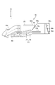
- FIG. 1 is a cross-sectional view showing a schematic configuration of an internal combustion engine according to one embodiment of the present invention
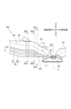
- FIG. FIG. 2 is a diagram showing a three-dimensional model of an intake system in the internal combustion engine of FIG. 1
- FIG. 2 is a cross-sectional view of a portion of the main flow path and the upstream end side portion of the main partition in the internal combustion engine of FIG. 1 ; It is the figure which looked at a part of main flow path shown in FIG. 3 from the upstream.
- FIG. 2 is a three-dimensional model of an intake system in the internal combustion engine of FIG. 1 when a tumble valve, which is an intake control valve, is closed and a throttle valve is opened to a predetermined minute opening.
- FIG. 2 is a three-dimensional model of the intake system in the internal combustion engine of FIG. 1 when the tumble valve is closed and the throttle valve is opened to an opening larger than a predetermined minute opening.
- FIG. 2 is a three-dimensional model of the intake system in the internal combustion engine of FIG. 1, when both the tumble valve and the throttle valve are fully open;
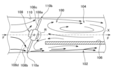
- FIG. 2 is a view of a three-dimensional model of the internal combustion engine of FIG. 1 including a portion of the intake passage on the downstream side of the throttle valve and the downstream side of the tumble valve and the exhaust port, viewed in a direction perpendicular to the cylinder axis and the direction of intake air flow;
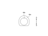
- FIG. 9 is a cross-sectional view of the three-dimensional model of FIG. 8 taken along line IXA-IXA;
- FIG. 9 is a cross-sectional view of the three-dimensional model of FIG. 8 along line IXB-IXB;
- FIG. 9 is a cross-sectional view of the three-dimensional model of FIG. 8 at a position along line IXC-IXC;
- FIG. 4 is a diagram for explaining the flow of intake air through a butterfly valve;
- FIG. 10 is a further diagram for explaining the flow of intake air by the butterfly valve;
- FIG. 2 is a diagram for explaining the flow of intake air around a throttle valve in the internal combustion engine of FIG. 1;
- FIG. 2 is a diagram showing simulation results of intake air flow around a throttle valve in the internal combustion engine of FIG. 1;
- FIG. 14 is a cross-sectional view of the intake passage along line XIVA-XIVA in the simulation model of FIG. 13;
- FIG. 14 is a cross-sectional view of the intake passage along line XIVB-XIVB in the simulation model of FIG. 13;
- FIG. 2 is a diagram showing a modification of the intake structure of the internal combustion engine of FIG. 1;
- FIG. 1 is a cross-sectional view of an internal combustion engine 10 along an axis (cylinder axis) C of a cylinder bore 12b of a cylinder block 12 of the internal combustion engine 10.
- FIG. 1 is a cross-sectional view of an internal combustion engine 10 along an axis (cylinder axis) C of a cylinder bore 12b of a cylinder block 12 of the internal combustion engine 10.
- a piston 15 that reciprocates in the cylinder bore 12b of the cylinder block 12 is connected to the crankpin of the crankshaft 17 of the crankcase portion 16 by a connecting rod 18.
- a combustion chamber 20 is formed between the top surface 15a of the piston 15 slidably fitted in the cylinder bore 12b of the cylinder block 12 and the combustion chamber ceiling surface 14a of the cylinder head 14 facing the top surface 15a.
- the internal combustion engine 10 employs a SOHC type two-valve system, and a valve mechanism 22 is provided in the cylinder head 14 .
- a cylinder head cover 24 is overlaid on the cylinder head 14 so as to cover the valve mechanism 22 .
- an endless cam chain (not shown) is provided on one side of the crankcase portion 16, the cylinder block 12, and the cylinder head 14 in the crankshaft direction.
- a camshaft 26 and a crankshaft 17 are installed through a cam chain chamber, and the camshaft 26 rotates in synchronism with the crankshaft 17 at a rotation speed of 1/2.
- a spark plug (not shown) is inserted into the combustion chamber 20 from the opposite side of the cam chain chamber (the other side in the crankshaft direction) of the cylinder head 14 .
- an intake port 32 and an exhaust port 34 are formed so as to extend while curving in directions vertically separating from each other.
- the upstream end of the intake port 32 opens toward the upper side of the cylinder head 14 and is connected to an inlet pipe 36 to form a continuous intake passage 38.
- a throttle body 40 is connected to the upstream side of the inlet pipe 36. be.
- the downstream end of the exhaust port 34 opens downward from the cylinder head 14 and is connected to the exhaust pipe 42 .
- An exhaust purification device and a silencer may be provided downstream of the exhaust pipe 42 .
- a cylindrical intake valve guide 44 is integrally fitted to the curved outer wall portion 32a of the intake port 32 in the cylinder head 14.
- An intake valve 46 slidably supported by an intake valve guide 44 opens and closes an intake valve port 28 of the intake port 32 facing the combustion chamber 20 .
- an exhaust valve 50 slidably supported by an exhaust valve guide 48 integrally fitted to the curved outer wall portion 34a of the exhaust port 34 in the cylinder head 14 is an exhaust valve opening facing the combustion chamber 20 of the exhaust port 34. Open and close 30.
- the intake valve 46 and the exhaust valve 50 are biased upward by valve springs so that the head portions 46a and 50a thereof close the intake valve port 28 and the exhaust valve port 30 facing the combustion chamber 20, respectively.
- Stem ends 46b and 50b of the intake valve 46 and the exhaust valve 50 are pushed down by an intake rocker arm 56 and an exhaust rocker arm 58 that contact and oscillate with the intake cam and the exhaust cam of the camshaft 26, and the intake valve 46 and the exhaust valve 50 are opened at a predetermined timing.
- the exhaust valve 50 opens, the intake port 32 communicates with the combustion chamber 20, and the exhaust port 34 communicates with the combustion chamber 20, and intake and exhaust are performed at predetermined timings.
- An inlet pipe 36 is connected to the upstream end of the intake port 32 of the internal combustion engine 10 via an insulator 60 to form a continuous intake passage 38.
- a throttle body 40 is connected to the upstream side of the inlet pipe 36. be done.
- the throttle body 40 has an intake passage 40a with a substantially circular cross section forming part of the intake passage 38 communicating with the combustion chamber 20 of the internal combustion engine 10, and the upstream side of the intake passage 40a is connected to an air cleaner device (not shown).
- the throttle body 40 is rotatably supported in the throttle body 40 by a valve shaft, that is, a throttle valve shaft 40b which intersects the direction of flow of intake air in the intake passage 40a, that is, at right angles to the central axis of the intake passage 40a. It has a throttle valve 40c that can variably control the flow area of the intake passage 40a to open and close the intake passage 40a.
- the throttle valve 40c is of the butterfly type, and has a throttle valve shaft 40b and a disk-shaped valve body 40d that is fixed to the throttle valve shaft 40b and rotates integrally with the throttle valve shaft 40b.
- the throttle valve 40c is rotatable clockwise in FIG. 1 in the valve opening direction by the driver's operation or the like. It is urged counterclockwise in the valve closing direction so as to be in the fully closed position in contact with the wall surface.
- the opening direction and the closing direction of the throttle valve 40c may be opposite to each other.
- the intake structure S is configured to give a tumble swirl flow of the fuel-air mixture in the combustion chamber 20 in order to obtain more favorable combustion in the combustion chamber 20, i.e., vertical rotation. ing. That is, the intake passage 38 is divided along the direction of intake air flow by a partition portion 62 leading from the inlet pipe 36 to the intake port 32, and is configured such that the passing intake air generates a tumble flow within the combustion chamber 20. It is partitioned into a tumble channel 64 and a main channel 66 excluding the tumble channel 64 .
- the tumble flow path 64 corresponds to the first intake passage, and the main flow path 66 corresponds to the second intake passage. Note that the tumble channel 64 may also be referred to as a secondary channel.
- a partition 72 is provided in the tumble flow path 64 so as to continue mainly from the inlet pipe 36 to the intake port 32 .
- the tumble flow path 64 is partitioned into two intake passages 68 and 70 .
- One of the two intake passages 68 , 70 is the first tumble passage 68 and the other of them is the second tumble passage 70 .
- the first tumble flow path 68 corresponds to the third intake passage
- the second tumble flow path 70 corresponds to the fourth intake passage.
- the partition 62 that separates the tumble flow channel 64 and the main flow channel 66 is referred to as a main partition
- the partition 72 that separates the first tumble flow channel 68 and the second tumble flow channel 70 of the tumble flow channel 64 is called a secondary partition. It is called a partition.
- the main partition 62 extends like a plate in the direction of flow of intake air
- the sub-partition 72 also extends like a plate along the direction of the flow of intake air, for example, substantially parallel to the main partition 62 .
- the main partition 62 is provided so as to substantially bisect the intake passage 38 in the vertical direction, here so as to substantially extend on the central axis extending in the flow direction.
- the sub-partition 72 is provided so as to substantially bisect the tumble flow path 64 in the vertical direction, here so as to substantially extend on the central axis of the tumble flow path 64 extending in the flow direction.
- a tumble flow path 64 and a main flow path 66 partitioned by the main partition 62 are formed in the intake passage 38, and a first tumble flow path 68 and a first A second tumble channel 70 is formed closer to the main channel 66 than the tumble channel 68, that is, positioned between the first tumble channel 68 and the main channel 66.
- the main partition 62 extends so as to substantially bisect the intake passage 38 in the vertical direction
- the secondary partition 72 extends so as to substantially bisect the tumble flow passage 64 in the vertical direction.
- the cross-sectional area of the main channel 66 is clearly greater than the cross-sectional area of the first tumble channel 68 and clearly greater than the cross-sectional area of the second tumble channel 70 . Therefore, naturally, the sum of the cross-sectional area of the main channel 66 and the cross-sectional area of the second tumble channel 70 is clearly larger than the cross-sectional area of the first tumble channel 68 .
- each of the main partition 62 and the sub-partition 72 may be provided so as to be biased, for example, in one of the vertical directions.
- the ratio (SA1:SA2) between the sum SA1 of the cross-sectional area of the main channel 66 and the cross-sectional area of the second tumble channel 70 and the cross-sectional area SA2 of the first tumble channel 68 is 8:2 to 7: It should be set to 3. However, the ratio is not limited to that range.
- the lower portion of the intake passage 38 partitioned by the main partition 62 forms the tumble flow channel 64
- the upper portion forms the main flow channel 66
- the lower portion of the tumble flow channel 64 partitioned by the secondary partition 72 forms the first tumble flow.
- Channel 68, the upper portion of which constitutes secondary tumble channel 70 is not limited herein to such a top-to-bottom arrangement.
- the terms "top” and “bottom” of the intake passage 38 and the like refer to the direction from the crankshaft 17 to the cylinder head 14 or the cylinder head cover 24 in the direction of the cylinder axis C.
- the direction opposite to this "upward” direction that is, the direction from the cylinder head 14 side to the crankshaft 17 side is called the “downward” or “downward” direction
- the absolute “upward” or “downward” direction in space does not mean
- the "up” or “up” direction corresponds to the first direction
- the "down” or “down” direction corresponds to the second direction.
- the relationship it is also possible for the relationship to be reversed so that the "up” or “up” direction corresponds to the second direction and the "down” or “down” direction corresponds to the first direction.
- the main partition 62 continuously extends from the throttle valve 40c to the intake port 32 in the intake air flow direction F at a first predetermined distance.
- the sub-partition 72 extends continuously from the throttle valve 40c to the intake port 32 at a second predetermined distance in the intake flow direction F.
- the upstream end 72a of the sub-partition 72 extends further upstream than the upstream end 62a of the main partition 62 in the flow direction F of the intake air.
- the upstream end 72a of the sub-partition 72 that is, the edge 72at thereof, is positioned upstream in the intake air flow direction F from the upstream end 62a of the main partition 62, that is, the edge 62at thereof.
- the upstream side of the sub-partition 72 extends to the connecting pipe 77 between the inlet pipe 36 and the throttle body 40 .
- the upstream side of the main partition 62 extends to the connecting pipe 77 between the inlet pipe 36 and the throttle body 40 .
- the main partition 62 and the sub-partition 72 may be formed without providing the connection pipe 77 .
- the downstream end 62b of the main partition 62 extends further downstream than the downstream end 72b of the sub-partition 72, and the downstream edge 62bt of the downstream end 62b is the downstream edge of the downstream end 72b in the intake air flow direction F. Located downstream of 72bt.
- valve shaft 40b of the throttle valve 40c is orthogonal to the intake flow direction F of the intake passage 40a of the intake passage .
- the vertical direction is parallel to the paper, and the valve shaft 40b of the throttle valve 40c is perpendicular to the paper. Therefore, the valve shaft 40b of the throttle valve 40c intersects the flow direction F of the intake air and intersects the vertical direction, for example, the first direction.
- the valve shaft 40b of the throttle valve 40c is perpendicular to the vertical direction, such as the first direction, and the intake air flow direction F of the intake passage .
- a tumble valve 76 is provided in the main flow passage 66. Although the tumble valve 76 is provided on the inlet pipe 36 here, it may be provided on the connection pipe 77 .
- the tumble valve 76 is rotatably supported in the inlet pipe 36 by a valve shaft 76b that intersects the main flow path 66 perpendicularly to the direction of intake air flow, i.e., perpendicular to the central axis of the main flow path 66, and opens and closes the main flow path 66. configured to be able to
- the tumble valve 76 is of the butterfly type, and has a valve shaft 76b and a substantially disk-shaped valve body 76c that is fixed to the valve shaft 76b and rotates integrally with the valve shaft 76b.
- the tumble valve 76 is configured with the valve body 76c, which is a single valve member that rotates integrally with the valve shaft 76b.
- the valve shaft 76b of the tumble valve 76 is parallel to the throttle valve shaft 40b here, it does not have to be parallel.
- the tumble valve 76 may also be called a tumble control valve, TCV, or the like, and corresponds to the intake control valve of the present invention.
- FIG. 2 shows a three-dimensional model M1 of the intake system of the internal combustion engine 10, particularly the intake system on the downstream side.
- FIG. 2 is a view of the three-dimensional model M1 from the left-right direction (perpendicular to the up-down direction), and is a view from the back side of the page of FIG.
- FIG. 2 is a view of the three-dimensional model M1 viewed from a direction orthogonal to the valve axis 46c of the intake valve 46 and orthogonal to the extending direction of the main partition 62 and the extending direction of the sub-partition 72.
- a throttle valve 40c and a tumble valve 76 are represented in the three-dimensional model M1.
- FIG. 3 shows a cross-sectional view of a portion of the main flow passage 66 and a portion of the main partition portion 62 on the upstream end 62a side, along the intake air flow direction. Further, FIG. 4 shows a view of part of the main flow path 66 shown in FIG. 3 as seen from the upstream side.
- the upstream end side of the main flow path 66 has a tapered portion 66a that tapers from the upstream side to the downstream side in the intake air flow direction.
- the tapered portion 66a is located between the upstream end 62a of the main partition portion 62 and the installation position of the tumble valve 76 in the main flow passage 66, and is a portion whose cross-sectional area decreases toward the downstream side in the intake flow direction.
- the upstream end 62a of the main partition 62 is thinnest on the side of the edge 62at and is formed so that the wall thickness increases toward the downstream side (see FIG. 3).
- the upstream side of the tapered portion 66a is substantially D-shaped as shown in FIG.
- a circular passage portion 66b having a substantially circular cross section is directly connected to the downstream side of the tapered portion 66a.
- the installation position of the tumble valve 76 which is an intake control valve capable of opening and closing the main flow passage 66, is determined in this circular passage portion 66b. Therefore, like the throttle valve 40c, the tumble valve 76 includes a disc-shaped valve body 76c fixed to the valve shaft 76b and integrally rotating therewith.
- the tumble valve 76 is selectively controlled to be fully open or fully closed by an ECU 80 described below, and its structure or configuration is simple.
- the tapered portion 66a and the circular passage portion 66b are formed in the connecting pipe 77, they may be formed in the inlet pipe .
- the internal combustion engine 10 is provided with fuel injection valves 78 and 79 .
- the fuel injection valve 78 is provided downstream of the throttle valve 40c and the tumble valve 76. As shown in FIG.
- the fuel injection valve 78 is provided in the inlet pipe 36 so as to face the main flow path 66 and is provided so as to inject fuel toward the intake port 32 . More specifically, fuel injection valve 78 is provided to inject fuel toward intake valve 46 via main flow path 66 .
- the fuel injection amount and injection timing from the fuel injection valve 78 are controlled in association with control of the throttle valve 40c and the tumble valve 76, respectively.
- Another fuel injection valve 79 is provided to inject fuel into the intake passage on the downstream side of the throttle valve 40c and the upstream side of the sub-partition portion 72.
- the amount of fuel injection from the fuel injection valve 79 and its injection timing are related to the amount of fuel injection from the fuel injection valve 78 and its injection timing, or the amount of fuel injection from the fuel injection valve 78 and its injection timing. can be controlled by
- An ECU (electronic control unit) 80 that controls the internal combustion engine 10 has a configuration as a so-called computer, and includes an intake control section 82 and a fuel injection control section 84 .
- the ECU 80 analyzes the operating state of the internal combustion engine 10 based on outputs from various sensors such as an engine rotation speed sensor and an engine load sensor, and controls the respective operations of the throttle valve 40c and the tumble valve 76 by the intake control unit 82. do.
- the throttle valve 40c can be opened to an arbitrary degree of opening by the ECU 80, and can be controlled to the degree of opening shown in FIGS.
- the ECU 80 controls each operation of the fuel injection valves 78 and 79 by means of the fuel injection control section 84 based on the analyzed operating state of the internal combustion engine 10 .
- the ECU 80 stores programs and various data for these controls.
- the ECU 80 substantially draws intake air from the tumble flow path 64, particularly from the first tumble flow path 68, more preferably only from the first tumble flow path 68.
- the tumble valve 76 is closed, and the throttle valve 40c is controlled to a predetermined small opening degree (see FIG. 5).
- the flow of intake air is promoted as schematically shown by the arrows in FIG. form a stream.
- the first tumble flow path 68 has a relatively small cross-sectional area, it is possible to increase the flow velocity even with an intake air amount suitable for a low load region, and to form a strong tumble flow.
- the ECU 80 when the operating state of the internal combustion engine 10 is in the medium load range, the ECU 80 operates the tumble valve 76 so that the intake air is taken in from the first tumble flow path 68 and the second tumble flow path 70, that is, the tumble flow path 64. It closes and controls the opening of the throttle valve 40c to be larger than a predetermined minute opening (see FIG. 6). At this time, the throttle valve 40c is controlled to have an opening degree smaller than that of full opening, but may be controlled to fully open. As a result, the flow of intake air is promoted as schematically shown by the arrows in FIG. A tumble flow is formed in the combustion chamber 20 .
- the intake air from the first and second tumble flow passages 68 and 70 forms the tumble flow, even in the medium load range where a larger amount of intake air is required than in the low load range, the necessary intake air amount is secured and strong A tumble flow can be formed.
- the fuel injection from the fuel injection valves 78 and 79 is controlled so that the air-fuel ratio becomes lean, but forming a tumble flow effectively can cause combustion.
- the ECU 80 causes the intake air to be taken in from the tumble flow path 64 including the first tumble flow path 68 and the second tumble flow path 70 and the main flow path 66.
- the tumble valve 76 is opened, here fully opened, and the throttle valve 40c is controlled to an opening larger than a predetermined small opening such as fully open (see FIG. 7).
- intake air flows as schematically shown by arrows in FIG. A tumble flow is preferably achieved in the chamber 20, otherwise a suitable in-cylinder flow velocity is achieved.
- the fuel injection from the fuel injection valves 78 and 79 is controlled so that the air-fuel ratio becomes stoichiometric, and a more suitable cylinder flow velocity is realized. Combustion can be caused more effectively.
- the tumble valve 76 is opened and the throttle valve 40c is opened to draw in intake air from the tumble flow path 64 and the main flow path 66.
- the intake structure S of the internal combustion engine 10 is designed to increase the amount of intake air by the intake air from the main flow path 66 and to more preferably secure the tumble performance by the intake air from the tumble flow path 64. It has further configurations and shapes. Further explanation is given below. Note that the following configuration, for example, the action and effect of the confluence portion 86, which enables more favorable tumble performance due to intake air from the tumble flow path 64, is established even when the tumble valve 76 is closed.
- a confluence portion 86 is formed on the downstream side of the tumble flow channel 64 .
- the confluence portion 86 is provided at a point where the first tumble flow path 68 and the second tumble flow path 70 merge on the downstream side thereof.
- the tumble flow path 64 joins the main flow path 66 via the confluence portion 86 .
- the confluence portion 86 is formed in the cylinder head 14 .
- the confluence portion 86 is formed as part of the intake port 32 .
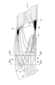
- FIG. 8 shows a three-dimensional model M2 including the portion of the intake passage 38 on the downstream side of the throttle valve 40c and the tumble valve 76 and the exhaust passage of the exhaust port 34.
- FIG. 8 is a view of the three-dimensional model M2 from a direction orthogonal to the cylinder axis C and orthogonal to the intake flow direction F.
- FIG. 9A A cross-sectional view of the solid model M2 along the line IXA-IXA in FIG. 8 is shown in FIG. 9A, and a cross-sectional view of the solid model M2 along the line IXB-IXB in FIG. 8 is shown in FIG.
- FIG. 9C A cross-sectional view of the solid model M2 at a position along line IXC-IXC of 8 is shown in FIG. 9C.
- Line IXA-IXA in FIG. 8 passes near the upstream end of intake port 32, line IXB-IXB in FIG. passes near the downstream edge of All of these lines IXA-IXA to IXC-IXC are parallel to the cylinder axis C in FIG.
- the first tumble channel 68 and the second tumble channel 70 have generally the same shape and size.
- each of the first tumble flow path 68 and the second tumble flow path 70 smoothly extends from the upstream side to the downstream side without significantly changing its shape or size in the intake air flow direction.
- the first tumble flow path 68 and the second tumble flow path 70 are connected to the confluence portion 86 .
- the confluence portion 86 is connected to the main flow path 66 downstream of the downstream edge 62bt of the downstream end 62b of the main partition 62 (see FIGS. 1 and 8).
- the first tumble flow path 68 and the second tumble flow path 70 enter the main flow path 66 via the edge of the downstream end 72b of the sub-partition portion 72, that is, the confluence portion 86 downstream of the downstream edge 72bt. will be connected. Therefore, the intake air passing through the first tumble flow path 68 and the second tumble flow path 70 of the tumble flow path 64 can have strong directivity.
- the line L1 defined to extend in the intake flow direction at the confluence portion 86 intersects the cylinder axis C at an angle ⁇ 1 close to a right angle.
- line L2 intersects the cylinder axis C at an angle .theta.2 smaller than the angle .theta.1.
- the confluence portion 86 is partitioned so that the intake air from the tumble flow passage 64 via the confluence portion 86 flows into the combustion chamber 20 at a smaller entrance angle than the intake air from the main flow passage 66.
- the intake air passing through the tumble flow path 64 can be introduced into the combustion chamber 20 while maintaining strong directivity, and a strong tumble flow can be generated in the combustion chamber 20, for example.
- advance angle refers to the angle at which the intake air flowing into the combustion chamber 20 flows into the combustion chamber 20.
- the tumble channel 64 is defined to have a downwardly convex curved shape
- the main channel 66 is defined to have an upwardly convex curved shape. formed.
- FIG. 9B shows that the first tumble flow path 68 and the second tumble flow path 70 communicate with the upstream end of the confluence portion 86 .
- FIG. 1 shows one side TA1 of the cross section in the imaginary plane.
- the side TA1 of the upstream end 86u of the merging portion 86 is longer than the vertical length of the cross section 68A of the first tumble flow channel 68 and the vertical length of the cross section 70A of the second tumble flow channel 70, respectively. is clearly long.
- the cross-sectional area of each of the first tumble flow path 68 and the second tumble flow path 70 areas S1 and S2 in FIG.
- the intake air from the first tumble flow path 68 and the intake air from the second tumble flow path 70 can preferably flow into the confluence portion 86 . More specifically, when intake air flows through the first tumble flow path 68 and the second tumble flow path 70, the cross-sectional area of the confluence portion 86 is the cross-sectional area of the first tumble flow path 68 and the second tumble flow path 70, respectively. Since it is larger, the amount of intake air is less likely to be restricted at the merging portion 86, and an amount of intake air suitable for the operating range of the middle load range, for example, can be ensured.
- side TA2 in FIG. 9C is shorter than side TA1 in FIG. 9B. That is, toward the downstream side, the cross-sectional area of the confluence portion 86 of the tumble flow channel 64 tends to be smaller at the cross-sectional location in FIG. 9C than at the side TA1 in FIG. 9B, for example.
- the confluence portion 86 is sectioned so as to generally taper from the upstream end portion of the confluence portion 86 toward the downstream side.
- the upstream end 86u of the merging portion 86 is larger than the sum of the cross-sectional areas of the first tumble flow path 68 and the second tumble flow path 70 (for example, the sum of the area S1 of the cross section 68A and the area S2 of the cross section 70A).
- the area (cross-sectional area) in the cross section orthogonal to the flow direction on the downstream side becomes smaller.
- the intake air from the tumble channel 64 can flow into the combustion chamber 20 at a high flow velocity and preferably form a tumble flow.
- the cross-sectional area perpendicular to the flow direction on the downstream side of the upstream end of the confluence portion 86 cannot be made smaller than the sum of the cross-sectional areas of the first tumble flow channel 68 and the second tumble flow channel 70. , may be realized by means other than tapering.
- the other end half 40g is positioned downstream in the intake air flow direction F with respect to the valve shaft 40b, and is at an obtuse angle with the corresponding inner wall surface 38a downstream of the other end half 40g. form ⁇ . 5, the valve body 40d of the throttle valve 40c is inclined, so that the first gap G1 is wider than the second gap G2 in the intake air flow direction F. Located upstream.
- Each of the first gap G1 and the second gap G2 has a gap width equal to or less than the thickness of the main partition 62.
- the thickness of the main partition 62 is preferably the average thickness of the main partition 62 extending in the intake air flow direction.
- each of the first gap G1 and the second gap G2 preferably has a gap width of 3 mm or less (0 ⁇ gap width ⁇ 3 mm), more preferably 2 mm or less (0 ⁇ gap width ⁇ 2 mm).
- the sub-partitions 72 are also formed to have approximately the same thickness as the main partitions 62 . That is, in the present embodiment, each of the first gap G1 and the second gap G2 has a gap width equal to or less than the thickness of the sub-partition 72 .
- the first gap G1 has a maximum width in FIGS. 1 and 3, and is formed so that the width of the gap becomes smaller as it progresses to the left and right (the direction perpendicular to the paper surface in FIGS. 1 and 3). Good.
- the second gap G2 has a maximum width in FIGS. 1 and 3, and is preferably formed so that the width of the gap decreases as it progresses to the left and right.
- the widths of the first gap G1 and the second gap G2 are not limited to these widths, and may be designed and formed so as to achieve the effects described below.
- FIG. 10 Note that the description similar to the description below based on FIGS. 10 and 11 is described in detail in JP-A-2019-23459.
- FIG. 10 when the intake passage 100 is provided with a partition portion 106 that separates the tumble flow passage 102 and the main flow passage 104, and the butterfly valve 108 is provided upstream of the partition portion 106, the butterfly valve 108 gradually opens.
- FIG. 4 is a diagram schematically showing the flow of intake air when the valve is open (when it is in a slightly open state).
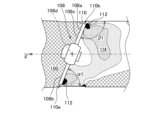
- FIG. 11 is a diagram mainly showing the pressure on the downstream side when the butterfly valve 108 shown in FIG. 10 is gradually opened.
- the butterfly valve 108 is rotatable in the clockwise direction R in FIG. 10 in the valve opening direction. It is biased counterclockwise in the valve closing direction so that the other end half body 108c, which rotates while abutting against the formed inner wall surface 110, is positioned at the fully closed position where it abuts against the same inner wall surface 110. As shown in FIG.
- One end side half 108b of the butterfly valve 108 in the fully closed state has an acute contact angle with the inner wall surface 110 of the intake passage 100 on the downstream side in the intake air flow direction F, and the other end side half 108c has an acute angle of contact with the intake air flow direction F.
- the contact angle of the inner wall surface 110 of the intake passage 100 on the downstream side in the direction F is an obtuse angle.
- the butterfly valve 108 is inclined, its one end half 108b is positioned upstream of the intake passage 100 with respect to the valve shaft 108d, and the other end half 108c of the butterfly valve 108 is Located downstream of the intake passage 100 .
- the angle ⁇ 1 between the one end half 108b of the butterfly valve 108 and the inner wall surface 110 of the intake passage 100 is an acute angle.
- the angle ⁇ 1 formed with the inner wall surface 110 is an obtuse angle.
- a strong negative pressure is generated in the region 112 immediately downstream of the obtuse angle side gap 110a and the acute angle side gap 110b (black area in FIG. 11), and the valve shaft 108d of the butterfly valve 108 is pushed.
- a wide negative pressure area 114 (dotted hatched area in FIG. 11) is generated in the downstream range of the butterfly valve 108 including. That is, as shown in FIG. 11, the portion of the intake passage 100 on the downstream side of the butterfly valve 108 is separated along the intake air flow direction F by the partition portion 106 having a surface substantially parallel to the valve shaft 108d of the butterfly valve 108.
- the channel 104 with the larger cross-sectional area is downstream of the other end half 108c, and the channel 102 with the smaller cross-sectional area is located downstream. If arranged on the downstream side of the one end side half 108b, when the butterfly valve 108 is gradually opened, the momentum of the intake air passing through the butterfly valve 108 and flowing toward the flow path 104 having a large cross-sectional area tends to weaken, and the momentum of the lost cross-sectional area decreases.
- the intake air flowing through the large flow path 104 is attracted by the negative pressure generated in the immediately downstream portions 112 (black portions in FIG.
- the channel 104 with a large cross-sectional area is used as the main channel, and the channel 102 with a small cross-sectional area is used as the tumble channel.
- the intake air that has once flowed into the main flow path 104 can be led to the tumble flow path 102 . That is, by setting the cross-sectional area of the main channel 104 to be larger than the cross-sectional area of the tumble channel 102, the intake air flowing through the tumble channel 102 can be strengthened.
- a first tumble channel 68 is located immediately downstream of one end half 40f of body 40d.
- the upstream end 72a of the sub-partitioning portion 72 extends further upstream than the upstream end 62a of the main partitioning portion 62.
- the sum of the cross-sectional area of the main channel 66 above the sub-partition 72 and the cross-sectional area of the second tumble channel 70 is the cross section of the first tumble channel 68 of the sub-partition 72.
- the throttle valve 40c is inclined when it is at a predetermined minute opening, and the one end side half of the throttle valve 40c located below the valve body 40d in the intake air flow direction F centering on the valve shaft 40b.
- the body 40f is located on the upstream side and forms an acute angle ⁇ with the corresponding wall surface on the downstream side thereof.
- An obtuse angle ⁇ is formed between the wall and its downstream side. Therefore, the butterfly valve 108, the tumble flow path 102, and the main flow path 104 of FIG. 70 can be mapped to Therefore, by opening the throttle valve 40c to a predetermined minute opening as described above, the intake structure S of the internal combustion engine of the present embodiment realizes the flow of intake air (see the arrow in FIG. 5) described based on FIG. can.
- the intake air that has passed through the second gap G2 can mainly flow to the main flow path 66 side, part or preferably all of it returns to the tumble flow path 64 side, together with the intake air that has passed through the first gap G1. , flow through the first tumble channel 68 .
- the intake air that has flowed downstream through the throttle valve 40c at a predetermined minute opening enters the first tumble flow path 68 and eventually flows into the tumble flow path 64 (see the arrow in FIG. 12).
- FIG. 14A shows the cross-sectional shape of the passage along line XIVA-XIVA in FIG. 13
- FIG. 14B shows the cross-sectional shape of the passage along line XIVB-XIVB in FIG.
- the position of FIG. 14A corresponds approximately to the position immediately upstream of the tapered portion 66a
- the position of FIG. 14B corresponds to the position of the circular passage portion 66b.
- the black portion is the portion where the pressure is the lowest, and occurred on the downstream side of the first gap G1 and the downstream side of the second gap G2.
- the intake air that has passed through the second gap G2 can move toward the main flow path 66 above the sub-partition 72 and the second tumble flow path 70 as indicated by the arrow FA, It flowed into the channel 68.
- the tumble flow path 64 including the first tumble flow path 68 and the second tumble flow path 70 and the main flow path 66 are formed. Therefore, by using one, a plurality, or all of them according to the operating state of the internal combustion engine, it is possible to secure the intake air amount according to the operating state.
- the valve shaft 40b of the throttle valve 40c intersects the vertical direction and the intake flow direction F of the intake passage 38, and the throttle valve 40c can be opened to a plurality of openings including a predetermined minute opening. Therefore, when the throttle valve 40c is opened to a predetermined minute opening, the first gap G1 formed between the throttle valve 40c and the intake passage wall surface 38c is located on the first tumble flow path 68 side, and the throttle valve The second gap G2 formed between 40c and the intake passage wall surface 38c is positioned on the main flow path 66 side. Furthermore, the upstream end 72a of the sub-partition 72 extends further upstream than the upstream end 62a of the main partition 62 in the intake flow direction F. As shown in FIG. Therefore, the intake air that has passed through the second gap G2 is urged toward the first tumble flow path 68 and is allowed to flow there. Therefore, tumble performance can be ensured.
- Such a reverse flow phenomenon when the throttle valve 40c is opened to a predetermined small degree of opening is established even when the tumble valve 76 is not provided.
- the tumble valve 76 is provided in the intake structure S of the internal combustion engine 10. allow the inspiratory air to flow to the As described above, the intake structure S of the internal combustion engine 10 configured as described above is provided with the tumble valve 76 for opening and closing the main flow path 66, but it is only opened fully open and fully closed, and its structure or configuration is not complicated. .
- the valve shaft 40b of the throttle valve 40c is orthogonal to the vertical direction and the intake flow direction F of the intake passage . Therefore, when the throttle valve 40c is opened to a predetermined minute opening, the first gap G1 can be preferably positioned on the first tumble flow path 68 side, and the second gap G2 can be positioned on the main flow path 66 side. be able to. Therefore, at that time, the flow of intake air to the first tumble flow path 68 through the second gap G2 can be encouraged more preferably.
- the cross section of the circular passage portion 66b of the main flow passage 66 at the installation position of the tumble valve 76 is substantially circular. Therefore, the degree of blockage of the main flow path 66 by the tumble valve 76 when the valve is closed can be increased more easily.
- the intake structure S includes the confluence portion 86 described above.
- the intake air when the throttle valve 40c is controlled to a predetermined minute opening, even if the intake air flows into the second tumble flow path 70, the intake air will flow through the first tumble flow path whose main purpose is to flow the intake air at that time. It joins the intake air of 68 at the junction 86 and is taken into the combustion chamber 20 . Therefore, at this time, the intake air from the tumble flow path 64 including the intake air flowing through the second tumble flow path 70 can be given a strong directivity, and the tumble flow in the combustion chamber 20 can be favorably strengthened. Tumble performance can be further secured.
- the number of sub-partitions is not limited to one, and may be plural.
- the tumble flow path 64 can be divided into a third intake passage corresponding to the first tumble flow passage 68 and a fourth intake passage corresponding to the second tumble flow passage 70. It becomes possible to divide into three or more intake passages, ie, intake passage sections, including the .
- the plurality of divided intake passage portions should preferably be connected to the main flow passage 66 via the confluence portion 86 and then to the combustion chamber 20, similar to the first and second tumble flow passages 68 and 70 described above. In this case, the plurality of sub-partitions may be provided in the tumble flow channel 64 separately from each other in the vertical direction.
- various members that define the intake passage of the internal combustion engine 10, particularly the intake passage on the downstream side of the throttle valve 40c, are preferably manufactured mainly by casting. As a result, it is possible to realize various shapes such as a downwardly convex tumble channel 64 and an upwardly convex main channel 66 . It should be noted that the present disclosure does not exclude the production of the member that defines the intake passage by a method other than casting.
- a resonator 90 is provided so as to communicate with the tumble flow path 64 .
- the resonator 90 communicates with the first tumble flow path 68 of the tumble flow paths 64 via a communication pipe 94 defining a communication path 92 .
- the resonator 90 may communicate with the second tumble channel 70 .
- the second tumble flow path is formed above the first tumble flow path, that is, on the first direction side, and the main stream is formed above the tumble flow path including these, that is, on the first direction side. made a road.
- the second tumble flow path may be formed below the first tumble flow path, and the main flow path may be provided below the tumble flow path including these.
- the throttle 40c should be turned upside down in the drawing corresponding to FIG.
- the present disclosure permits the inclination of the throttle valve 40c to be reversed vertically. Also in this case, the above effects described with reference to FIGS. 5 and 10 to 12 can be produced in the same manner.
- Tumble passage (first intake passage) 66...Main passage (second intake passage), 68...First tumble passage (third intake passage) 70...Second tumble flow path (fourth intake passage), 72...Partition (secondary partition) 76...Tumble valve (intake control valve), 86...Joining portion, 90...Resonator S...Intake structure, G1...First gap, G2...Second gap
Abstract
The present disclosure is directed to a configuration, in internal combustion engines configured with the intake manifold being divided by partitions, that makes it possible, without requiring a complex-structure intake control valve in addition to the throttle valve, both to ensure a suctioned air volume according to driving conditions and to ensure a tumble effect. An intake structure S for an internal combustion engine according to one embodiment of the present invention is provided with: a primary partition 62 that partitions an intake passage 38 on the downstream side of a throttle valve 40c into a first intake passage 64 serving as a flow path for generating a tumble flow, and a second intake passage 66 on a first-direction side thereof; and a secondary partition 72 that partitions the first intake passage 64 into a third intake passage 68 and a fourth intake passage 70 on the first-direction side thereof. The valve stem of the throttle valve intersects the first direction and the intake flow direction. The upstream end of the secondary partition 72 extends further to the upstream side beyond the upstream end of the primary partition 62 in the intake flow direction. The throttle valve is configured so as to enable opening to a plurality of opening degrees including a prescribed minute opening degree.
Description
本発明は、吸気通路を複数に分ける仕切部が設けられる内燃機関の吸気構造に関する。
The present invention relates to an intake structure for an internal combustion engine provided with partitions for dividing an intake passage into a plurality of sections.
スロットル弁の下流側の吸気通路が、仕切部により複数の通路に分けられる内燃機関の吸気構造が種々提案されている。例えば、特許文献1の内燃機関の吸気構造では、スロットル弁の下流側にタンブル弁を設け、そのタンブル弁の下流側にインレットパイプから吸気ポートへと続けて仕切部である仕切板部を設け、この仕切板部により吸気通路を上下の下側副通路と上側主流路とに仕切ることが行われる。下側副通路がタンブル流路となり、タンブル弁は上側主流路を実質的に開閉するものである。
Various intake structures for internal combustion engines have been proposed in which the intake passage on the downstream side of the throttle valve is divided into a plurality of passages by partitions. For example, in the intake structure for an internal combustion engine disclosed in Patent Document 1, a tumble valve is provided downstream of the throttle valve, and a partition plate portion, which is a partition portion, is provided downstream of the tumble valve from the inlet pipe to the intake port, The partition plate partitions the intake passage into a lower secondary passage and an upper main passage. The lower secondary passage serves as a tumble passage, and the tumble valve substantially opens and closes the upper main passage.
また、特許文献2が開示する内燃機関では、スロットル弁の下流側に吸気制御弁が設けられ、更にその下流側の吸気通路に、吸入空気の流れ方向に沿った横板状部材が配設されている。横板状部材の数が1つのときと、2つ以上のときの内燃機関が開示されている。特許文献2の記載によれば、横板状部材を複数形成し、内燃機関の運転条件に応じた吸気制御弁の開度を決定することで、吸気制御弁の中間開度においても吸入空気の流れを乱さず、安定したガス流動を生成させる。
Further, in the internal combustion engine disclosed in Patent Document 2, an intake control valve is provided downstream of the throttle valve, and a horizontal plate-shaped member is disposed along the flow direction of the intake air in the intake passage downstream of the throttle valve. ing. An internal combustion engine with one horizontal plate member and two or more horizontal plate members are disclosed. According to the description of Patent Document 2, by forming a plurality of horizontal plate-shaped members and determining the opening degree of the intake control valve according to the operating conditions of the internal combustion engine, the amount of intake air is reduced even at intermediate opening degrees of the intake control valve. Generates a stable gas flow without disturbing the flow.
ところで、内燃機関を好適に作動させるためには、その内燃機関の運転状態に応じた吸入空気量を確保することと、燃焼効率を高めるためにタンブル流などの渦流を燃焼室で好適に生じさせることとの両立が望まれる。しかし、例えば特許文献2の構成では、スロットル弁に加えて吸気制御弁を設けることが必須であり、タンブル流を生じさせるときなどに吸気制御弁を様々な角度に精度よく調整することが必要不可欠である。これは吸気制御弁の構造の複雑化の方向にあり、課題を有する。
By the way, in order to operate the internal combustion engine properly, it is necessary to secure an intake air amount corresponding to the operating state of the internal combustion engine, and to suitably generate a swirling flow such as a tumble flow in the combustion chamber in order to increase the combustion efficiency. It is desirable to be compatible with However, for example, in the configuration of Patent Document 2, it is essential to provide an intake control valve in addition to the throttle valve, and it is essential to accurately adjust the intake control valve to various angles when generating a tumble flow. is. This is in the direction of complicating the structure of the intake control valve, which poses a problem.
本発明の目的は、吸気通路が仕切部により分けられるように構成された内燃機関において、スロットル弁の他に構造の複雑な吸気制御弁を必要とすることなしに、運転状態に応じた吸入空気量の確保とタンブル性能の確保との両立を可能にする構成を提供することにある。
SUMMARY OF THE INVENTION An object of the present invention is to provide an internal combustion engine in which an intake passage is divided by a partition, without requiring an intake control valve having a complicated structure in addition to a throttle valve. An object of the present invention is to provide a configuration that enables both securing of amount and securing of tumble performance.
上記目的を達成するために、本発明の一態様は、
スロットル弁の下流側の吸気通路を、タンブル流を発生させるためのタンブル流路となる第1吸気通路と、該第1吸気通路の第1方向側に位置する第2吸気通路とに仕切る主仕切部と、
前記第1吸気通路に第3吸気通路と、該第3吸気通路の前記第1方向側に第4吸気通路とを形成するように設けられる副仕切部と、
を備え、
前記スロットル弁の弁軸は前記第1方向及び前記吸気通路の吸気流れ方向に交差し、
前記副仕切部の上流端は、前記吸気流れ方向において、前記主仕切部の上流端よりも上流側に延び、
前記スロットル弁は、所定微小開度を含む複数の開度に開くことができるように構成されている
ことを特徴とする内燃機関の吸気構造
を提供する。 In order to achieve the above object, one aspect of the present invention is
A main partition that divides an intake passage on the downstream side of the throttle valve into a first intake passage serving as a tumble flow passage for generating a tumble flow, and a second intake passage located on the first direction side of the first intake passage. Department and
a sub-partition provided to form a third intake passage in the first intake passage and a fourth intake passage on the first direction side of the third intake passage;
with
a valve shaft of the throttle valve intersects the first direction and an intake flow direction of the intake passage;
an upstream end of the sub-partition extends further upstream than an upstream end of the main partition in the intake air flow direction;
Provided is an intake structure for an internal combustion engine, wherein the throttle valve is configured to be able to open to a plurality of openings including a predetermined minute opening.
上記構成によれば、スロットル弁の下流側の吸気通路をタンブル流を発生させるためのタンブル流路となる第1吸気通路と、第2吸気通路とに仕切る主仕切部と、第1吸気通路に、第3吸気通路と第4吸気通路とを形成するように設けられる副仕切部が備えられる。したがって、内燃機関の運転状態に応じてそれらの1つ、複数又は全てを使用することで、運転状態に応じた吸入空気量を確保することができる。また、スロットル弁の弁軸は上記第1方向及び吸気通路の吸気流れ方向に交差し、副仕切部の上流端は、吸気流れ方向において、主仕切部の上流端よりも上流側に延び、スロットル弁は、所定微小開度を含む複数の開度に開くことができるように構成されている。したがって、スロットル弁が所定微小開度に開いたとき、第3吸気通路に吸気の流れを促すことができ、タンブル性能を確保することができる。そして、上記構成では、スロットル弁の操作でタンブル流を実現できるので、構造の複雑な吸気制御弁を必ずしも必要としない。
According to the above configuration, the main partition section that divides the intake passage downstream of the throttle valve into the first intake passage serving as a tumble flow passage for generating a tumble flow and the second intake passage; , a sub-partition provided to form a third intake passage and a fourth intake passage. Therefore, by using one, a plurality, or all of them according to the operating state of the internal combustion engine, it is possible to secure the intake air amount according to the operating state. Further, the valve shaft of the throttle valve intersects the first direction and the intake air flow direction of the intake passage, and the upstream end of the secondary partition extends upstream of the upstream end of the main partition in the intake air flow direction, The valve is configured to be able to open to a plurality of openings including a predetermined minute opening. Therefore, when the throttle valve is opened to a predetermined minute opening, it is possible to promote the flow of intake air through the third intake passage, thereby ensuring tumble performance. Further, in the above configuration, a tumble flow can be realized by operating the throttle valve, so an intake control valve with a complicated structure is not necessarily required.
好ましくは、前記スロットル弁が前記所定微小開度に開いているとき、該スロットル弁の弁体と吸気通路壁面との間に第1の隙間部及び第2の隙間部が形成され、前記第1の隙間部は、前記スロットル弁の前記弁軸を間に挟んで、前記第2の隙間部の反対側に位置する。この構成により、スロットル弁が所定微小開度に開いているとき、第3吸気通路に吸気の流れを好適に促すことができる。
Preferably, when the throttle valve is opened to the predetermined minute opening, a first clearance and a second clearance are formed between the valve body of the throttle valve and the wall surface of the intake passage, and the first clearance is formed. is located on the opposite side of the second clearance with the valve shaft of the throttle valve interposed therebetween. With this configuration, when the throttle valve is opened to a predetermined minute opening, it is possible to favorably promote the flow of intake air through the third intake passage.
好ましくは、前記第1の隙間部及び前記第2の隙間部のそれぞれは前記主仕切部の厚さ以下の隙間幅を有する。この構成により、スロットル弁が所定微小開度に開いているとき、第3吸気通路に吸気の流れをより好適に促すことができる。
Preferably, each of the first gap and the second gap has a gap width equal to or less than the thickness of the main partition. With this configuration, when the throttle valve is opened to a predetermined minute opening, it is possible to favorably promote the flow of intake air through the third intake passage.
好ましくは、前記スロットル弁の前記弁軸は前記第1方向及び前記吸気通路の吸気流れ方向に直交する。この構成により、スロットル弁が所定微小開度に開いているとき、吸気の流れをより好適に第3吸気通路に促すことができる。
Preferably, the valve shaft of the throttle valve is perpendicular to the first direction and the intake flow direction of the intake passage. With this configuration, when the throttle valve is opened to a predetermined minute opening, the flow of intake air can be more favorably urged to the third intake passage.
好ましくは、前記第2吸気通路の断面積と前記第4吸気通路の断面積の和は、前記第3吸気通路の断面積よりも大きく、前記第2吸気通路を開閉可能である吸気制御弁が更に設けられている。第2吸気通路の断面積と第4吸気通路の断面積の和を第3吸気通路の断面積よりも大きくすることにより、スロットル弁が所定微小開度に開いているとき、第2吸気通路及び第4吸気通路側に一旦流れた吸気の流れを、第3吸気通路により好適に促すことができる。また、吸気制御弁を設けることで、例えばスロットル弁が所定微小開度に開いているときに第2吸気通路を閉じて、第3吸気通路への吸気の流れをより一層促すことができる。
Preferably, the sum of the cross-sectional area of the second intake passage and the cross-sectional area of the fourth intake passage is larger than the cross-sectional area of the third intake passage, and an intake control valve capable of opening and closing the second intake passage is provided. is further provided. By making the sum of the cross-sectional area of the second intake passage and the cross-sectional area of the fourth intake passage larger than the cross-sectional area of the third intake passage, when the throttle valve is opened to a predetermined minute opening, the second intake passage and The flow of intake air that has once flowed to the fourth intake passage can be favorably promoted by the third intake passage. Further, by providing the intake control valve, for example, when the throttle valve is opened to a predetermined minute opening, the second intake passage can be closed to further promote the flow of intake air to the third intake passage.
好ましくは、前記吸気制御弁の設置位置における前記第2吸気通路の断面は略円形である。この構成により、閉弁時の吸気制御弁による第2吸気通路の閉塞の度合いをより容易に高めることができる。
Preferably, the cross section of the second intake passage at the installation position of the intake control valve is substantially circular. With this configuration, it is possible to more easily increase the degree of blockage of the second intake passage by the intake control valve when the valve is closed.
好ましくは、前記第2吸気通路において前記主仕切部の上流端と前記吸気制御弁の設置位置との間に、吸気流れ方向において下流側に向けて断面積が小さくなる先細り部が設けられている。この構成により、第2吸気通路への吸気の流れをより好適に滑らかにすることができる。
Preferably, the second intake passage is provided with a tapered portion whose cross-sectional area decreases toward the downstream side in the intake air flow direction between the upstream end of the main partition and the installation position of the intake control valve. . With this configuration, the flow of intake air to the second intake passage can be more preferably smoothed.
前記第1吸気通路にレゾネータが連通しているとよい。この構成により、第1吸気通路からの吸気の流動を高め、よってタンブル流を強化することができる。
A resonator may communicate with the first intake passage. This configuration can enhance the flow of intake air from the first intake passage, thereby enhancing the tumble flow.
好ましくは、前述の吸気構造は、前記第3吸気通路と前記第4吸気通路とが合流する合流部であって、該合流部を介して前記第1吸気通路は前記第2吸気通路に合流する、合流部を更に備える。この構成により、第3吸気通路と第4吸気通路とを備える第1吸気通路からの吸気に強い指向性を持たせることができ、タンブル性能を更に確保することができる。
Preferably, the intake structure described above is a junction where the third intake passage and the fourth intake passage join, and the first intake passage joins the second intake passage via the junction. , and a confluence. With this configuration, the intake air from the first intake passage having the third intake passage and the fourth intake passage can have strong directivity, and the tumble performance can be further ensured.
好ましくは、前記第3吸気通路及び前記第4吸気通路の断面積の和よりも、前記合流部の上流側端部よりも下流側の流れ方向に直交する断面での面積が小さくなるように、前記合流部は区画形成されている。この構成により、第3吸気通路からの吸気と第4吸気通路からの吸気とが合流部で合流して第2吸気通路に流れるとき、吸気の流速を速い状態に保つことが可能になる。
Preferably, the cross-sectional area perpendicular to the flow direction on the downstream side of the upstream end of the merging portion is smaller than the sum of the cross-sectional areas of the third intake passage and the fourth intake passage. The confluence section is partitioned. With this configuration, when the intake air from the third intake passage and the intake air from the fourth intake passage merge at the confluence portion and flow into the second intake passage, the flow velocity of the intake air can be kept high.
好ましくは、前記第2吸気通路からの吸気よりも、前記合流部を介しての前記第1吸気通路からの吸気が小さい進入角で燃焼室に流入するように、前記合流部は区画形成されている。この構成により、第1吸気通路を通った吸気が強い指向性を持ったまま燃焼室に導入可能になるため、燃焼室で強いタンブル流を発生させることができる。
Preferably, the merging portion is defined so that the intake air from the first intake passage through the merging portion flows into the combustion chamber at a smaller entrance angle than the intake air from the second intake passage. there is With this configuration, the intake air that has passed through the first intake passage can be introduced into the combustion chamber while maintaining strong directivity, so that a strong tumble flow can be generated in the combustion chamber.
本発明の上記態様によれば、上記構成を備えるので、吸気通路が仕切部により分けられるように構成された内燃機関において、スロットル弁の他に構造の複雑な吸気制御弁を必要とすることなしに、運転状態に応じた吸入空気量の確保とタンブル性能の確保との両立を図ることが可能になる。
According to the above aspect of the present invention, since it has the above configuration, an intake control valve with a complicated structure is not required in addition to the throttle valve in an internal combustion engine configured so that the intake passage is divided by the partition. In addition, it is possible to ensure both the intake air amount according to the operating state and the tumble performance.
以下、本発明に係る実施形態を添付図に基づいて説明する。同一の部品(又は構成)には同一の符号を付してあり、それらの名称及び機能も同じである。したがって、それらについての詳細な説明は繰返さない。
Hereinafter, an embodiment according to the present invention will be described based on the accompanying drawings. The same parts (or configurations) are given the same reference numerals, and their names and functions are also the same. Therefore, detailed description thereof will not be repeated.
本発明の一実施形態に係る内燃機関10の概略構成を図1に示す。図1は、内燃機関10のシリンダブロック12のシリンダボア12bの軸線(シリンダ軸線)Cに沿った、内燃機関10の断面図である。
A schematic configuration of an internal combustion engine 10 according to one embodiment of the present invention is shown in FIG. FIG. 1 is a cross-sectional view of an internal combustion engine 10 along an axis (cylinder axis) C of a cylinder bore 12b of a cylinder block 12 of the internal combustion engine 10. FIG.
シリンダブロック12のシリンダボア12b内を往復動するピストン15は、クランクケース部16のクランク軸17のクランクピンと、コネクティングロッド18により連結されている。シリンダブロック12のシリンダボア12b内に摺動自在に嵌合されるピストン15の頂面15aと、頂面15aが対向するシリンダヘッド14の燃焼室天井面14aとの間には燃焼室20が構成される。
A piston 15 that reciprocates in the cylinder bore 12b of the cylinder block 12 is connected to the crankpin of the crankshaft 17 of the crankcase portion 16 by a connecting rod 18. A combustion chamber 20 is formed between the top surface 15a of the piston 15 slidably fitted in the cylinder bore 12b of the cylinder block 12 and the combustion chamber ceiling surface 14a of the cylinder head 14 facing the top surface 15a. be.
内燃機関10は、SOHC型式の2バルブシステムを採用しており、シリンダヘッド14に動弁機構22が設けられている。動弁機構22を覆うように、シリンダヘッド14にはシリンダヘッドカバー24が重ねられて被せられる。シリンダヘッドカバー24内の動弁機構22に動力伝達を行うため、図示しない無端状のカムチェーンが、クランクケース部16、シリンダブロック12、シリンダヘッド14のクランク軸方向の一方側に設けられた図示しないカムチェーン室を通って、カム軸26とクランク軸17との間に架設され、カム軸26はクランク軸17に同期して1/2の回転速度で回転する。なお、シリンダヘッド14においてカムチェーン室と反対側(クランク軸方向の他方側)から燃焼室20内に向かって点火プラグ(不図示)が嵌挿されている。
The internal combustion engine 10 employs a SOHC type two-valve system, and a valve mechanism 22 is provided in the cylinder head 14 . A cylinder head cover 24 is overlaid on the cylinder head 14 so as to cover the valve mechanism 22 . In order to transmit power to the valve mechanism 22 in the cylinder head cover 24, an endless cam chain (not shown) is provided on one side of the crankcase portion 16, the cylinder block 12, and the cylinder head 14 in the crankshaft direction. A camshaft 26 and a crankshaft 17 are installed through a cam chain chamber, and the camshaft 26 rotates in synchronism with the crankshaft 17 at a rotation speed of 1/2. A spark plug (not shown) is inserted into the combustion chamber 20 from the opposite side of the cam chain chamber (the other side in the crankshaft direction) of the cylinder head 14 .
シリンダヘッド14において、燃焼室天井面14aに開口した吸気弁口28と排気弁口30からは、各々吸気ポート32と排気ポート34が互いに上下に離れる方向に湾曲しながら延出して形成される。吸気ポート32の上流端は、シリンダヘッド14の上方に向けて開口し、インレットパイプ36と接続して、連続した吸気通路38が構成され、インレットパイプ36の上流側に、スロットルボディ40が接続される。
In the cylinder head 14, from an intake valve port 28 and an exhaust valve port 30 that open to the ceiling surface 14a of the combustion chamber, an intake port 32 and an exhaust port 34 are formed so as to extend while curving in directions vertically separating from each other. The upstream end of the intake port 32 opens toward the upper side of the cylinder head 14 and is connected to an inlet pipe 36 to form a continuous intake passage 38. A throttle body 40 is connected to the upstream side of the inlet pipe 36. be.
排気ポート34の下流端は、シリンダヘッド14の下方に向けて開口し、排気管42に連結される。排気管42の下流側には、排気浄化装置及び消音装置が設けられ得る。
The downstream end of the exhaust port 34 opens downward from the cylinder head 14 and is connected to the exhaust pipe 42 . An exhaust purification device and a silencer may be provided downstream of the exhaust pipe 42 .
シリンダヘッド14における吸気ポート32の湾曲外壁部32aに一体に円筒状の吸気弁ガイド44が嵌着されている。吸気弁ガイド44に摺動可能に支持された吸気弁46が、吸気ポート32の燃焼室20に臨む吸気弁口28を開閉する。
A cylindrical intake valve guide 44 is integrally fitted to the curved outer wall portion 32a of the intake port 32 in the cylinder head 14. An intake valve 46 slidably supported by an intake valve guide 44 opens and closes an intake valve port 28 of the intake port 32 facing the combustion chamber 20 .
また、シリンダヘッド14における排気ポート34の湾曲外壁部34aに一体に嵌着された排気弁ガイド48に摺動可能に支持された排気弁50が、排気ポート34の燃焼室20に臨む排気弁口30を開閉する。
Also, an exhaust valve 50 slidably supported by an exhaust valve guide 48 integrally fitted to the curved outer wall portion 34a of the exhaust port 34 in the cylinder head 14 is an exhaust valve opening facing the combustion chamber 20 of the exhaust port 34. Open and close 30.
吸気弁46及び排気弁50はその傘部46a、50aが、いずれも燃焼室20に臨む吸気弁口28、排気弁口30を閉じるように、弁ばねにより上方に付勢されている。カム軸26の吸気カム、排気カムに当接揺動する吸気ロッカアーム56、排気ロッカアーム58によって、吸気弁46、排気弁50のステムエンド46b、50bが押し下げられて、所定のタイミングで吸気弁46、排気弁50が開弁し、吸気ポート32と燃焼室20、また、排気ポート34と燃焼室20が連通し、所定のタイミングの吸気、排気がなされる。
The intake valve 46 and the exhaust valve 50 are biased upward by valve springs so that the head portions 46a and 50a thereof close the intake valve port 28 and the exhaust valve port 30 facing the combustion chamber 20, respectively. Stem ends 46b and 50b of the intake valve 46 and the exhaust valve 50 are pushed down by an intake rocker arm 56 and an exhaust rocker arm 58 that contact and oscillate with the intake cam and the exhaust cam of the camshaft 26, and the intake valve 46 and the exhaust valve 50 are opened at a predetermined timing. The exhaust valve 50 opens, the intake port 32 communicates with the combustion chamber 20, and the exhaust port 34 communicates with the combustion chamber 20, and intake and exhaust are performed at predetermined timings.
内燃機関10の吸気ポート32の上流端には、インシュレ-タ60を介してインレットパイプ36が接続して、連続した吸気通路38が構成され、インレットパイプ36の上流側に、スロットルボディ40が接続される。スロットルボディ40は、内燃機関10の燃焼室20に連なる吸気通路38の一部を構成する断面略円形の吸気路40aを有し、その上流側は、図示しないエアクリーナ装置に接続している。
An inlet pipe 36 is connected to the upstream end of the intake port 32 of the internal combustion engine 10 via an insulator 60 to form a continuous intake passage 38. A throttle body 40 is connected to the upstream side of the inlet pipe 36. be done. The throttle body 40 has an intake passage 40a with a substantially circular cross section forming part of the intake passage 38 communicating with the combustion chamber 20 of the internal combustion engine 10, and the upstream side of the intake passage 40a is connected to an air cleaner device (not shown).
スロットルボディ40は、その吸気路40aの吸気の流れ方向と垂直、すなわち吸気路40aの中心軸線と直角に交差する弁軸つまりスロットル弁軸40bによってスロットルボディ40内に回転自在に軸支されて、吸気路40aの流路面積を可変制御し、吸気路40aを開閉し得るスロットル弁40cを備えている。スロットル弁40cはバタフライ式のもので、スロットル弁軸40bと、スロットル弁軸40bに固定される共に一体的に回転する円盤状の弁体40dとを有している。
The throttle body 40 is rotatably supported in the throttle body 40 by a valve shaft, that is, a throttle valve shaft 40b which intersects the direction of flow of intake air in the intake passage 40a, that is, at right angles to the central axis of the intake passage 40a. It has a throttle valve 40c that can variably control the flow area of the intake passage 40a to open and close the intake passage 40a. The throttle valve 40c is of the butterfly type, and has a throttle valve shaft 40b and a disk-shaped valve body 40d that is fixed to the throttle valve shaft 40b and rotates integrally with the throttle valve shaft 40b.
スロットル弁40cは運転者の操作等により、図1において時計回りに開弁方向に回動可能となっているとともに、図示しない復帰ばねにより、弁体40dはそれの縁部が吸気路40aの内壁面に当接する全閉位置に位置するように、閉弁方向に反時計回りに付勢されている。なお、スロットル弁40cのこの開弁方向と閉弁方向とはそれぞれ逆向きであってもよい。
The throttle valve 40c is rotatable clockwise in FIG. 1 in the valve opening direction by the driver's operation or the like. It is urged counterclockwise in the valve closing direction so as to be in the fully closed position in contact with the wall surface. The opening direction and the closing direction of the throttle valve 40c may be opposite to each other.
以上のような内燃機関10において、燃焼室20でのより好ましい燃焼を得るために燃焼室20において燃料・空気混合気のタンブル渦流つまりタンブル流、すなわち縦回転を与えるための吸気構造Sが構成されている。すなわち、吸気通路38は、インレットパイプ36から吸気ポート32へと続く仕切部62によって、吸気流れ方向に沿って分割され、通った吸気が燃焼室20内でタンブル流を発生するように構成されたタンブル流路64と、タンブル流路64を除く主流路66とに仕切られている。タンブル流路64が第1吸気通路に相当し、主流路66が第2吸気通路に相当する。なお、タンブル流路64は副通路と称されてもよい。
In the internal combustion engine 10 as described above, the intake structure S is configured to give a tumble swirl flow of the fuel-air mixture in the combustion chamber 20 in order to obtain more favorable combustion in the combustion chamber 20, i.e., vertical rotation. ing. That is, the intake passage 38 is divided along the direction of intake air flow by a partition portion 62 leading from the inlet pipe 36 to the intake port 32, and is configured such that the passing intake air generates a tumble flow within the combustion chamber 20. It is partitioned into a tumble channel 64 and a main channel 66 excluding the tumble channel 64 . The tumble flow path 64 corresponds to the first intake passage, and the main flow path 66 corresponds to the second intake passage. Note that the tumble channel 64 may also be referred to as a secondary channel.
更に、タンブル流路64に、仕切部72が主にインレットパイプ36から吸気ポート32へと続くように設けられている。仕切部72を設けることで、タンブル流路64に、2つの吸気通路68、70が区画形成される。2つの吸気通路68、70の一方は第1タンブル流路68であり、それらの他方は第2タンブル流路70である。第1タンブル流路68は第3吸気通路に相当し、第2タンブル流路70は第4吸気通路に相当する。
Furthermore, a partition 72 is provided in the tumble flow path 64 so as to continue mainly from the inlet pipe 36 to the intake port 32 . By providing the partition portion 72 , the tumble flow path 64 is partitioned into two intake passages 68 and 70 . One of the two intake passages 68 , 70 is the first tumble passage 68 and the other of them is the second tumble passage 70 . The first tumble flow path 68 corresponds to the third intake passage, and the second tumble flow path 70 corresponds to the fourth intake passage.
ここでは、タンブル流路64と主流路66とを仕切る仕切部62を主仕切部と称し、タンブル流路64の第1タンブル流路68と第2タンブル流路70とを仕切る仕切部72を副仕切部と称する。主仕切部62は吸気の流れ方向に板状に延在し、副仕切部72も主仕切部62に沿って、例えば略平行に、吸気の流れ方向に板状に延在する。主仕切部62は吸気通路38を実質的に上下方向において二分するように、ここでは流れ方向に延びる中心軸線上に実質的に延びるように設けられている。また、副仕切部72はタンブル流路64を実質的に上下方向において二分するように、ここでは流れ方向に延びるタンブル流路64の中心軸線上に実質的に延びるように設けられている。これにより、吸気通路38に、主仕切部62によって仕切られたタンブル流路64と主流路66が形成され、そのタンブル流路64に、副仕切部72によって第1タンブル流路68と、第1タンブル流路68よりも主流路66よりのつまり第1タンブル流路68と主流路66との間に位置する第2タンブル流路70とが形成される。ここでは、前述のように、主仕切部62は吸気通路38を実質的に上下方向において二分するように延び、かつ、副仕切部72はタンブル流路64を実質的に上下方向において二分するように延びるので、主流路66の断面積は、第1タンブル流路68の断面積よりも明らかに大きく、また第2タンブル流路70の断面積よりも明らかに大きい。よって、当然に、主流路66の断面積と第2タンブル流路70の断面積との和は、第1タンブル流路68の断面積よりも明らかに大きい。なお、主仕切部62及び副仕切部72のそれぞれは、例えば上下方向のいずれかに偏るように設けられてもよい。
Here, the partition 62 that separates the tumble flow channel 64 and the main flow channel 66 is referred to as a main partition, and the partition 72 that separates the first tumble flow channel 68 and the second tumble flow channel 70 of the tumble flow channel 64 is called a secondary partition. It is called a partition. The main partition 62 extends like a plate in the direction of flow of intake air, and the sub-partition 72 also extends like a plate along the direction of the flow of intake air, for example, substantially parallel to the main partition 62 . The main partition 62 is provided so as to substantially bisect the intake passage 38 in the vertical direction, here so as to substantially extend on the central axis extending in the flow direction. Further, the sub-partition 72 is provided so as to substantially bisect the tumble flow path 64 in the vertical direction, here so as to substantially extend on the central axis of the tumble flow path 64 extending in the flow direction. As a result, a tumble flow path 64 and a main flow path 66 partitioned by the main partition 62 are formed in the intake passage 38, and a first tumble flow path 68 and a first A second tumble channel 70 is formed closer to the main channel 66 than the tumble channel 68, that is, positioned between the first tumble channel 68 and the main channel 66. As shown in FIG. Here, as described above, the main partition 62 extends so as to substantially bisect the intake passage 38 in the vertical direction, and the secondary partition 72 extends so as to substantially bisect the tumble flow passage 64 in the vertical direction. , the cross-sectional area of the main channel 66 is clearly greater than the cross-sectional area of the first tumble channel 68 and clearly greater than the cross-sectional area of the second tumble channel 70 . Therefore, naturally, the sum of the cross-sectional area of the main channel 66 and the cross-sectional area of the second tumble channel 70 is clearly larger than the cross-sectional area of the first tumble channel 68 . In addition, each of the main partition 62 and the sub-partition 72 may be provided so as to be biased, for example, in one of the vertical directions.
なお、主流路66の断面積と第2タンブル流路70の断面積との和SA1と、第1タンブル流路68の断面積SA2との比(SA1:SA2)は、8:2~7:3に設定されるとよい。しかし、その比は、その範囲に限定されない。
The ratio (SA1:SA2) between the sum SA1 of the cross-sectional area of the main channel 66 and the cross-sectional area of the second tumble channel 70 and the cross-sectional area SA2 of the first tumble channel 68 is 8:2 to 7: It should be set to 3. However, the ratio is not limited to that range.
吸気通路38の主仕切部62によって仕切られた下側部分がタンブル流路64、上側部分が主流路66となり、タンブル流路64の副仕切部72によって仕切られた下側部分が第1タンブル流路68、上側部分が第2タンブル流路70となるが、本明細書においてはそれらはその上下配置に限定されない。なお、本明細書において、吸気通路38などについての「上」、「下」とは、シリンダ軸線C方向においてクランク軸17側からシリンダヘッド14ないしシリンダヘッドカバー24側の方向を「上」又は「上」方向、この「上」方向とは逆向きの方向つまりシリンダヘッド14側からクランク軸17側の方向を「下」又は「下」方向といい、空間上の絶対的な「上」、「下」の意味ではない。本明細書では、この「上」又は「上」方向は第1方向に相当し、「下」又は「下」方向は第2方向に相当する。ただし、この関係が逆になり、この「上」又は「上」方向が第2方向に対応し、「下」又は「下」方向が第1方向に対応するようになることも可能である。
The lower portion of the intake passage 38 partitioned by the main partition 62 forms the tumble flow channel 64, the upper portion forms the main flow channel 66, and the lower portion of the tumble flow channel 64 partitioned by the secondary partition 72 forms the first tumble flow. Channel 68, the upper portion of which constitutes secondary tumble channel 70, is not limited herein to such a top-to-bottom arrangement. In this specification, the terms "top" and "bottom" of the intake passage 38 and the like refer to the direction from the crankshaft 17 to the cylinder head 14 or the cylinder head cover 24 in the direction of the cylinder axis C. , the direction opposite to this "upward" direction, that is, the direction from the cylinder head 14 side to the crankshaft 17 side is called the "downward" or "downward" direction, and the absolute "upward" or "downward" direction in space. does not mean As used herein, the "up" or "up" direction corresponds to the first direction, and the "down" or "down" direction corresponds to the second direction. However, it is also possible for the relationship to be reversed so that the "up" or "up" direction corresponds to the second direction and the "down" or "down" direction corresponds to the first direction.
主仕切部62は、スロットル弁40cから吸気流れ方向Fに第1所定間隔離れた位置から吸気ポート32にまで連続して延びている。同様に、副仕切部72は、スロットル弁40cから吸気流れ方向Fに第2所定間隔離れた位置から吸気ポート32にまで連続して延びている。図1から明らかなように、副仕切部72の上流端72aは、吸気流れ方向Fにおいて、主仕切部62の上流端62aよりも上流側に延びている。つまり、副仕切部72の上流端72aつまりその端縁72atは、吸気流れ方向Fにおいて、主仕切部62の上流端62aつまりその縁部62atよりも上流側に位置している。ここでは、副仕切部72の上流側はインレットパイプ36とスロットルボディ40との間の接続管77にまで延びている。同じく、主仕切部62の上流側はインレットパイプ36とスロットルボディ40との間の接続管77にまで延びている。なお、接続管77を設けずに、主仕切部62と副仕切部72は形成されてもよい。なお、主仕切部62の下流端62bは、副仕切部72の下流端72bよりも下流側に延びていて、下流端62bの下流端縁62btは吸気流れ方向Fにおいて下流端72bの下流端縁72btよりも下流側に位置する。
The main partition 62 continuously extends from the throttle valve 40c to the intake port 32 in the intake air flow direction F at a first predetermined distance. Similarly, the sub-partition 72 extends continuously from the throttle valve 40c to the intake port 32 at a second predetermined distance in the intake flow direction F. As shown in FIG. As is clear from FIG. 1, the upstream end 72a of the sub-partition 72 extends further upstream than the upstream end 62a of the main partition 62 in the flow direction F of the intake air. In other words, the upstream end 72a of the sub-partition 72, that is, the edge 72at thereof, is positioned upstream in the intake air flow direction F from the upstream end 62a of the main partition 62, that is, the edge 62at thereof. Here, the upstream side of the sub-partition 72 extends to the connecting pipe 77 between the inlet pipe 36 and the throttle body 40 . Similarly, the upstream side of the main partition 62 extends to the connecting pipe 77 between the inlet pipe 36 and the throttle body 40 . Note that the main partition 62 and the sub-partition 72 may be formed without providing the connection pipe 77 . The downstream end 62b of the main partition 62 extends further downstream than the downstream end 72b of the sub-partition 72, and the downstream edge 62bt of the downstream end 62b is the downstream edge of the downstream end 72b in the intake air flow direction F. Located downstream of 72bt.
前述のように、スロットル弁40cの弁軸40bは、吸気通路38のうちの吸気路40aの吸気流れ方向Fと直交する。図1では、上下方向が紙面に平行であり、スロットル弁40cの弁軸40bは紙面に直交する。したがって、スロットル弁40cの弁軸40bは、吸気の流れ方向Fと交差するとともに、上下方向、例えば第1方向と交差する。特に、ここでは、スロットル弁40cの弁軸40bは、第1方向などの上下方向及び吸気通路38の吸気流れ方向Fに直交する。
As described above, the valve shaft 40b of the throttle valve 40c is orthogonal to the intake flow direction F of the intake passage 40a of the intake passage . In FIG. 1, the vertical direction is parallel to the paper, and the valve shaft 40b of the throttle valve 40c is perpendicular to the paper. Therefore, the valve shaft 40b of the throttle valve 40c intersects the flow direction F of the intake air and intersects the vertical direction, for example, the first direction. In particular, here, the valve shaft 40b of the throttle valve 40c is perpendicular to the vertical direction, such as the first direction, and the intake air flow direction F of the intake passage .
上記主流路66には、タンブル弁76が設けられている。ここでは、タンブル弁76は、インレットパイプ36に設けられているが、上記接続管77に設けられてもよい。タンブル弁76は、主流路66の吸気流れ方向と垂直、すなわち主流路66の中心軸線と直角に交差する弁軸76bによってインレットパイプ36内に回転自在に軸支されて、主流路66を開閉することができるように構成されている。タンブル弁76はバタフライ式のもので、弁軸76bと、この弁軸76bに固定される共に一体的に回転する略円盤状の弁体76cとを有している。このように、タンブル弁76は弁軸76bと一体的に回転する単一の弁部材である弁体76cを備えて構成されている。ただし、ここではタンブル弁76の弁軸76bはスロットル弁軸40bと平行であるが、平行でなくてもよい。なお、タンブル弁76は、タンブル制御弁、TCVなどとも称され得、本発明の吸気制御弁に相当する。
A tumble valve 76 is provided in the main flow passage 66. Although the tumble valve 76 is provided on the inlet pipe 36 here, it may be provided on the connection pipe 77 . The tumble valve 76 is rotatably supported in the inlet pipe 36 by a valve shaft 76b that intersects the main flow path 66 perpendicularly to the direction of intake air flow, i.e., perpendicular to the central axis of the main flow path 66, and opens and closes the main flow path 66. configured to be able to The tumble valve 76 is of the butterfly type, and has a valve shaft 76b and a substantially disk-shaped valve body 76c that is fixed to the valve shaft 76b and rotates integrally with the valve shaft 76b. In this manner, the tumble valve 76 is configured with the valve body 76c, which is a single valve member that rotates integrally with the valve shaft 76b. However, although the valve shaft 76b of the tumble valve 76 is parallel to the throttle valve shaft 40b here, it does not have to be parallel. The tumble valve 76 may also be called a tumble control valve, TCV, or the like, and corresponds to the intake control valve of the present invention.
ここで、内燃機関10の吸気系、特に下流側の吸気系の立体モデルM1を図2に示す。図2は立体モデルM1の(上下方向に直交する)左右方向からの図であり、図1の紙面奥側からの図である。図2は、吸気弁46のバルブ軸線46cに直交する方向であって主仕切部62の延在方向及び副仕切部72の延在方向に対して直交する方向から立体モデルM1をみた図である。立体モデルM1では、スロットル弁40cと、タンブル弁76が表されている。また、図3に、主流路66の一部と主仕切部62の上流端62a側の部分との、吸気流れ方向に沿った断面図を示す。更に、図4に、図3に示す主流路66の一部を上流側からみた図を示す。
FIG. 2 shows a three-dimensional model M1 of the intake system of the internal combustion engine 10, particularly the intake system on the downstream side. FIG. 2 is a view of the three-dimensional model M1 from the left-right direction (perpendicular to the up-down direction), and is a view from the back side of the page of FIG. FIG. 2 is a view of the three-dimensional model M1 viewed from a direction orthogonal to the valve axis 46c of the intake valve 46 and orthogonal to the extending direction of the main partition 62 and the extending direction of the sub-partition 72. FIG. . A throttle valve 40c and a tumble valve 76 are represented in the three-dimensional model M1. 3 shows a cross-sectional view of a portion of the main flow passage 66 and a portion of the main partition portion 62 on the upstream end 62a side, along the intake air flow direction. Further, FIG. 4 shows a view of part of the main flow path 66 shown in FIG. 3 as seen from the upstream side.
図3及び図4に示すように、主流路66の上流端側は、吸気流れ方向において上流側から下流側に進むにしたがって先細りになる先細り部66aを有する。先細り部66aは、主流路66において主仕切部62の上流端62aとタンブル弁76の設置位置との間に位置し、吸気流れ方向において下流側に向けて断面積が小さくなる部分である。この先細り部66aを形成するように、主仕切部62の上流端62aはその端縁62at側で最も薄く、下流側に向けて肉厚が増すように形成されている(図3参照)。なお、先細り部66aの上流側は、図4に示すように略D型である。先細り部66aの下流側には断面が略円形の円形通路部66bが直接つながっている。主流路66を開閉可能である吸気制御弁であるタンブル弁76の設置位置は、この円形通路部66bに定められている。したがって、スロットル弁40cと同様に、タンブル弁76は、弁軸76bに固定される共に一体的に回転する円盤状の弁体76cを備える。このタンブル弁76は、以下のECU80により、全開及び全閉のいずれかの開度に選択的に制御されるものであり、その構造又は構成は簡易である。なお、先細り部66a及び円形通路部66bは接続管77において形成されているが、インレットパイプ36に形成されてもよい。
As shown in FIGS. 3 and 4, the upstream end side of the main flow path 66 has a tapered portion 66a that tapers from the upstream side to the downstream side in the intake air flow direction. The tapered portion 66a is located between the upstream end 62a of the main partition portion 62 and the installation position of the tumble valve 76 in the main flow passage 66, and is a portion whose cross-sectional area decreases toward the downstream side in the intake flow direction. To form the tapered portion 66a, the upstream end 62a of the main partition 62 is thinnest on the side of the edge 62at and is formed so that the wall thickness increases toward the downstream side (see FIG. 3). The upstream side of the tapered portion 66a is substantially D-shaped as shown in FIG. A circular passage portion 66b having a substantially circular cross section is directly connected to the downstream side of the tapered portion 66a. The installation position of the tumble valve 76, which is an intake control valve capable of opening and closing the main flow passage 66, is determined in this circular passage portion 66b. Therefore, like the throttle valve 40c, the tumble valve 76 includes a disc-shaped valve body 76c fixed to the valve shaft 76b and integrally rotating therewith. The tumble valve 76 is selectively controlled to be fully open or fully closed by an ECU 80 described below, and its structure or configuration is simple. Although the tapered portion 66a and the circular passage portion 66b are formed in the connecting pipe 77, they may be formed in the inlet pipe .
なお、図1から理解できるように、スロットル弁40cが全閉位置にあるとき、弁軸40bを中心として、吸気流れ方向Fにおいて、スロットル弁40cの弁体40dの下側に位置する一端側半体40fは、上流側に位置し、一端側半体76fの下流側において、対応する吸気通路38の内壁面38aの部分と鋭角をなす。また、このとき、弁軸40bを中心として、吸気流れ方向Fにおいて、スロットル弁40cの弁体40dの上側に位置する他端側半体40gは、下流側に位置し、他端側半体40gの下流側において、対応する内壁面38aの部分と鈍角をなす。この角度関係は、スロットル弁40cがわずかに開く所定微小開度にあるとき同様に成立する。
As can be understood from FIG. 1, when the throttle valve 40c is in the fully closed position, one end side half located below the valve body 40d of the throttle valve 40c in the intake air flow direction F centering on the valve stem 40b. The body 40f is positioned upstream and forms an acute angle with the corresponding portion of the inner wall surface 38a of the intake passage 38 downstream of the one end half 76f. Also, at this time, the other end side half 40g positioned above the valve body 40d of the throttle valve 40c in the intake air flow direction F centering on the valve shaft 40b is positioned downstream. forms an obtuse angle with the corresponding portion of the inner wall surface 38a. This angular relationship is similarly established when the throttle valve 40c is at a predetermined minute opening that is slightly opened.
内燃機関10では、燃料噴射弁78、79が設けられている。燃料噴射弁78は、スロットル弁40c及びタンブル弁76の下流側に設けられている。ここでは、燃料噴射弁78は、主流路66に臨むようにインレットパイプ36に設けられ、吸気ポート32に向けて燃料を噴射するように設けられている。より具体的には、燃料噴射弁78は主流路66を介して吸気弁46に向けて燃料を噴射するように設けられている。この燃料噴射弁78からの燃料噴射量及びその噴射タイミングは、スロットル弁40c及びタンブル弁76のそれぞれの制御と関連付けて制御される。
The internal combustion engine 10 is provided with fuel injection valves 78 and 79 . The fuel injection valve 78 is provided downstream of the throttle valve 40c and the tumble valve 76. As shown in FIG. Here, the fuel injection valve 78 is provided in the inlet pipe 36 so as to face the main flow path 66 and is provided so as to inject fuel toward the intake port 32 . More specifically, fuel injection valve 78 is provided to inject fuel toward intake valve 46 via main flow path 66 . The fuel injection amount and injection timing from the fuel injection valve 78 are controlled in association with control of the throttle valve 40c and the tumble valve 76, respectively.
また、もう一つの燃料噴射弁79はスロットル弁40cの下流側かつ副仕切部72の上流側の吸気通路に燃料を噴射するように設けられている。この燃料噴射弁79からの燃料噴射量及びその噴射タイミングは、燃料噴射弁78からの燃料噴射量及びその噴射タイミングと同様に、又は、燃料噴射弁78からの燃料噴射量及びその噴射タイミングと関連付けて制御され得る。
Another fuel injection valve 79 is provided to inject fuel into the intake passage on the downstream side of the throttle valve 40c and the upstream side of the sub-partition portion 72. The amount of fuel injection from the fuel injection valve 79 and its injection timing are related to the amount of fuel injection from the fuel injection valve 78 and its injection timing, or the amount of fuel injection from the fuel injection valve 78 and its injection timing. can be controlled by
内燃機関10を制御するECU(電子制御ユニット)80は、所謂コンピュータとしての構成を備え、吸気制御部82及び燃料噴射制御部84を備えている。ECU80は、エンジン回転速度センサ、エンジン負荷センサなどの各種センサからの出力に基づいて内燃機関10の運転状態を解析して、吸気制御部82により、スロットル弁40c及びタンブル弁76の各作動を制御する。なお、スロットル弁40cはECU80により任意の開度に開くことができ、図5から図7に示す開度に制御され得る。また、ECU80は、解析した内燃機関10の運転状態に基づいて、燃料噴射制御部84により、燃料噴射弁78、79の各作動を制御する。なお、ECU80には、これらの制御のためのプログラム及び各種データが記憶されている。
An ECU (electronic control unit) 80 that controls the internal combustion engine 10 has a configuration as a so-called computer, and includes an intake control section 82 and a fuel injection control section 84 . The ECU 80 analyzes the operating state of the internal combustion engine 10 based on outputs from various sensors such as an engine rotation speed sensor and an engine load sensor, and controls the respective operations of the throttle valve 40c and the tumble valve 76 by the intake control unit 82. do. The throttle valve 40c can be opened to an arbitrary degree of opening by the ECU 80, and can be controlled to the degree of opening shown in FIGS. Further, the ECU 80 controls each operation of the fuel injection valves 78 and 79 by means of the fuel injection control section 84 based on the analyzed operating state of the internal combustion engine 10 . The ECU 80 stores programs and various data for these controls.
ここで、スロットル弁40c及びタンブル弁76の制御について図5から図7に基づいて説明する。なお、図5から図7はそれぞれ、図2に示す立体モデルM1においてスロットル弁40c及びタンブル弁76の各開度を調整したものである。
Here, the control of the throttle valve 40c and the tumble valve 76 will be described with reference to Figs. 5 to 7 are obtained by adjusting the respective opening degrees of the throttle valve 40c and the tumble valve 76 in the three-dimensional model M1 shown in FIG.
例えば内燃機関10の運転状態が低負荷領域にあるとき、ECU80は、タンブル流路64から、特に第1タンブル流路68から、より好ましくは第1タンブル流路68のみから実質的に吸気を吸入させるように、タンブル弁76を閉じ、スロットル弁40cを所定微小開度に制御する(図5参照)。これにより、図5に矢印で模式的に示すように吸気の流れが促され、低負荷領域に即した吸入空気量を確保するとともに、第1タンブル流路68からの吸気で燃焼室20にタンブル流を形成させる。第1タンブル流路68は比較的断面積が小さいため、低負荷領域に即した吸入空気量でも流速を早くすることができ、強いタンブル流を形成することができる。ここでは、内燃機関10の運転状態が低負荷領域にあるとき、燃料噴射弁78、79からの燃料噴射は空燃比がリーンになるように制御されるが、タンブル流を形成することで効果的に燃焼を生じさせることができる。なお、図5に示すとき、図5に矢印で模式的に示すように吸気の流れが促されるが、この流れについては後述する。
For example, when the operating state of the internal combustion engine 10 is in the low load region, the ECU 80 substantially draws intake air from the tumble flow path 64, particularly from the first tumble flow path 68, more preferably only from the first tumble flow path 68. The tumble valve 76 is closed, and the throttle valve 40c is controlled to a predetermined small opening degree (see FIG. 5). As a result, the flow of intake air is promoted as schematically shown by the arrows in FIG. form a stream. Since the first tumble flow path 68 has a relatively small cross-sectional area, it is possible to increase the flow velocity even with an intake air amount suitable for a low load region, and to form a strong tumble flow. Here, when the operating state of the internal combustion engine 10 is in the low load region, the fuel injection from the fuel injection valves 78 and 79 is controlled so that the air-fuel ratio becomes lean, but forming a tumble flow is effective. can cause combustion. It should be noted that, when shown in FIG. 5, the flow of intake air is promoted as schematically indicated by arrows in FIG. 5, and this flow will be described later.
また、例えば内燃機関10の運転状態が中負荷領域にあるとき、ECU80は、第1タンブル流路68及び第2タンブル流路70つまりタンブル流路64から吸気を吸入させるように、タンブル弁76を閉じ、スロットル弁40cを所定微小開度よりも大きな開度に制御する(図6参照)。なお、このときのスロットル弁40cは、全開よりは小さな開度に制御されるが、全開に制御されてもよい。これにより、図6に矢印で模式的に示すように吸気の流れが促され、中負荷領域に即した吸入空気量を確保するとともに、第1及び第2タンブル流路68、70からの吸気で燃焼室20にタンブル流を形成させる。第1及び第2タンブル流路68、70からの吸気でタンブル流を形成するため、低負荷領域より多くの吸入空気量が必要な中負荷領域においても必要な吸入空気量を確保しつつ、強いタンブル流を形成することができる。ここでは、内燃機関10の運転状態が中負荷領域にあるとき、燃料噴射弁78、79からの燃料噴射は空燃比がリーンになるように制御されるが、タンブル流を形成することで効果的に燃焼を生じさせることができる。
Further, for example, when the operating state of the internal combustion engine 10 is in the medium load range, the ECU 80 operates the tumble valve 76 so that the intake air is taken in from the first tumble flow path 68 and the second tumble flow path 70, that is, the tumble flow path 64. It closes and controls the opening of the throttle valve 40c to be larger than a predetermined minute opening (see FIG. 6). At this time, the throttle valve 40c is controlled to have an opening degree smaller than that of full opening, but may be controlled to fully open. As a result, the flow of intake air is promoted as schematically shown by the arrows in FIG. A tumble flow is formed in the combustion chamber 20 . Since the intake air from the first and second tumble flow passages 68 and 70 forms the tumble flow, even in the medium load range where a larger amount of intake air is required than in the low load range, the necessary intake air amount is secured and strong A tumble flow can be formed. Here, when the operating state of the internal combustion engine 10 is in the middle load region, the fuel injection from the fuel injection valves 78 and 79 is controlled so that the air-fuel ratio becomes lean, but forming a tumble flow effectively can cause combustion.
更に、例えば内燃機関10の運転状態が高負荷領域にあるとき、ECU80は、第1タンブル流路68及び第2タンブル流路70を含むタンブル流路64並びに主流路66から吸気を吸入させるように、タンブル弁76を開き、ここでは全開に開き、スロットル弁40cを全開など所定微小開度よりも大きな開度に制御する(図7参照)。これにより、図7に矢印で模式的に示すように吸気の流れが生じ、高負荷領域に即した吸入空気量を確保するとともに、第1及び第2タンブル流路68、70からの吸気で燃焼室20に好ましくはタンブル流を、そうでなくても好適な筒内流速を実現させる。ここでは、内燃機関10の運転状態が高負荷領域にあるとき、燃料噴射弁78、79からの燃料噴射は空燃比がストイキになるように制御され、更に好適な筒内流速を実現することでより効果的に燃焼を生じさせることができる。
Furthermore, for example, when the operating state of the internal combustion engine 10 is in the high load region, the ECU 80 causes the intake air to be taken in from the tumble flow path 64 including the first tumble flow path 68 and the second tumble flow path 70 and the main flow path 66. , the tumble valve 76 is opened, here fully opened, and the throttle valve 40c is controlled to an opening larger than a predetermined small opening such as fully open (see FIG. 7). As a result, intake air flows as schematically shown by arrows in FIG. A tumble flow is preferably achieved in the chamber 20, otherwise a suitable in-cylinder flow velocity is achieved. Here, when the operating state of the internal combustion engine 10 is in the high load region, the fuel injection from the fuel injection valves 78 and 79 is controlled so that the air-fuel ratio becomes stoichiometric, and a more suitable cylinder flow velocity is realized. Combustion can be caused more effectively.
例えば、内燃機関10の運転状態が高負荷領域にあるとき、前述のように、タンブル弁76を開き、スロットル弁40cを開くことで、タンブル流路64及び主流路66から吸気を吸入させる。このときに、主流路66からの吸気により吸入空気量をより多くし、かつ、タンブル流路64からの吸気によるタンブル性能をより好適に確保可能にするように、内燃機関10の吸気構造Sは更なる構成及び形状を有する。以下、更に説明する。なお、タンブル流路64からの吸気によるタンブル性能をより好適に確保可能にする以下の構成、例えば合流部86による作用効果は、タンブル弁76が閉じられているときにも成立する。
For example, when the operating state of the internal combustion engine 10 is in the high load region, as described above, the tumble valve 76 is opened and the throttle valve 40c is opened to draw in intake air from the tumble flow path 64 and the main flow path 66. At this time, the intake structure S of the internal combustion engine 10 is designed to increase the amount of intake air by the intake air from the main flow path 66 and to more preferably secure the tumble performance by the intake air from the tumble flow path 64. It has further configurations and shapes. Further explanation is given below. Note that the following configuration, for example, the action and effect of the confluence portion 86, which enables more favorable tumble performance due to intake air from the tumble flow path 64, is established even when the tumble valve 76 is closed.
タンブル流路64の下流側には合流部86が区画形成されている。合流部86は、第1タンブル流路68及び第2タンブル流路70がその下流側で合流する個所に設けられている。そして、合流部86を介してタンブル流路64は主流路66に合流する。合流部86は、シリンダヘッド14に形成されている。ここでは、合流部86は吸気ポート32の一部として形成されている。
A confluence portion 86 is formed on the downstream side of the tumble flow channel 64 . The confluence portion 86 is provided at a point where the first tumble flow path 68 and the second tumble flow path 70 merge on the downstream side thereof. The tumble flow path 64 joins the main flow path 66 via the confluence portion 86 . The confluence portion 86 is formed in the cylinder head 14 . Here, the confluence portion 86 is formed as part of the intake port 32 .
ここで、図8に、スロットル弁40c及びタンブル弁76の下流側の吸気通路38の部分及び排気ポート34の排気通路を含む立体モデルM2を示す。図8はシリンダ軸線Cに直交するとともに吸気流れ方向Fに直交する方向からの立体モデルM2の図である。図8のIXA-IXAに沿った位置での立体モデルM2の断面図を図9Aに示し、図8のIXB-IXB線に沿った位置での立体モデルM2の断面図を図9Bに示し、図8のIXC-IXC線に沿った位置での立体モデルM2の断面図を図9Cに示す。図8のIXA-IXA線は吸気ポート32の上流端近傍を通り、図8のIXB-IXB線は副仕切部72の下流端縁近傍を通り、図8のIXC-IXC線は主仕切部62の下流端縁の近傍を通る。これらのIXA-IXA線からIXC-IXC線は、いずれも、図8においてシリンダ軸線Cに平行である。
Here, FIG. 8 shows a three-dimensional model M2 including the portion of the intake passage 38 on the downstream side of the throttle valve 40c and the tumble valve 76 and the exhaust passage of the exhaust port 34. As shown in FIG. FIG. 8 is a view of the three-dimensional model M2 from a direction orthogonal to the cylinder axis C and orthogonal to the intake flow direction F. FIG. A cross-sectional view of the solid model M2 along the line IXA-IXA in FIG. 8 is shown in FIG. 9A, and a cross-sectional view of the solid model M2 along the line IXB-IXB in FIG. 8 is shown in FIG. A cross-sectional view of the solid model M2 at a position along line IXC-IXC of 8 is shown in FIG. 9C. Line IXA-IXA in FIG. 8 passes near the upstream end of intake port 32, line IXB-IXB in FIG. passes near the downstream edge of All of these lines IXA-IXA to IXC-IXC are parallel to the cylinder axis C in FIG.
図9A及び図9Bにおいて、第1タンブル流路68と第2タンブル流路70とは概ね同じ形状及びサイズを有する。このように、第1タンブル流路68と第2タンブル流路70とのそれぞれは、その吸気流れ方向においてその形状又はサイズが大きく変わることなく、滑らかに上流側から下流側に至る。そして、第1タンブル流路68と第2タンブル流路70とは合流部86につながる。合流部86は、主仕切部62の下流端62bの縁部つまり下流端縁62btよりも下流側で主流路66につながる(図1及び図8参照)。この構成により、第1タンブル流路68と第2タンブル流路70とは副仕切部72の下流端72bの縁部つまり下流端縁72btよりも下流側の合流部86を経て、主流路66につながることになる。よって、タンブル流路64の第1タンブル流路68と第2タンブル流路70を通った吸気に指向性を強く持たせることができる。
9A and 9B, the first tumble channel 68 and the second tumble channel 70 have generally the same shape and size. Thus, each of the first tumble flow path 68 and the second tumble flow path 70 smoothly extends from the upstream side to the downstream side without significantly changing its shape or size in the intake air flow direction. The first tumble flow path 68 and the second tumble flow path 70 are connected to the confluence portion 86 . The confluence portion 86 is connected to the main flow path 66 downstream of the downstream edge 62bt of the downstream end 62b of the main partition 62 (see FIGS. 1 and 8). With this configuration, the first tumble flow path 68 and the second tumble flow path 70 enter the main flow path 66 via the edge of the downstream end 72b of the sub-partition portion 72, that is, the confluence portion 86 downstream of the downstream edge 72bt. will be connected. Therefore, the intake air passing through the first tumble flow path 68 and the second tumble flow path 70 of the tumble flow path 64 can have strong directivity.
図8において、合流部86において吸気流れ方向に延びるように定められる線L1が直角に近い角度θ1でシリンダ軸線Cに交わるのに対して、主流路66の下流端において流れ方向に延びるように定められる線L2が角度θ1よりも小さな角度θ2でシリンダ軸線Cに交わる。このように、主流路66からの吸気よりも、合流部86を介してのタンブル流路64からの吸気が小さい進入角で燃焼室20に流入するように、合流部86は区画形成されている。この構成により、タンブル流路64を通った吸気が強い指向性を持ったまま燃焼室20に導入可能になり、例えば燃焼室20で強いタンブル流を発生させることができる。なお、ここでいう進入角とは、燃焼室20に向けて流入する吸気の燃焼室20への流入の角度であり、例えばシリンダ軸線Cに直交するとともに吸気流れ方向に直交する方向からみた図8においてシリンダ軸線Cとの間でなす角度が大きいほど進入角は小さいということになる。
In FIG. 8, the line L1 defined to extend in the intake flow direction at the confluence portion 86 intersects the cylinder axis C at an angle θ1 close to a right angle. line L2 intersects the cylinder axis C at an angle .theta.2 smaller than the angle .theta.1. In this way, the confluence portion 86 is partitioned so that the intake air from the tumble flow passage 64 via the confluence portion 86 flows into the combustion chamber 20 at a smaller entrance angle than the intake air from the main flow passage 66. . With this configuration, the intake air passing through the tumble flow path 64 can be introduced into the combustion chamber 20 while maintaining strong directivity, and a strong tumble flow can be generated in the combustion chamber 20, for example. The term "advance angle" as used herein refers to the angle at which the intake air flowing into the combustion chamber 20 flows into the combustion chamber 20. For example, as seen in FIG. , the larger the angle formed with the cylinder axis C, the smaller the approach angle.
更に、図1及び図8から明らかなように、タンブル流路64は、下側に凸の湾曲形状を有するように区画形成され、主流路66は、上側に凸の湾曲形状を有するように区画形成されている。この構成により、上述のように、タンブル流路64からの吸気をより小さな進入角で燃焼室20に導くことが可能になり、また、主流路66からの吸気をより効果的に燃焼室20に導くことが可能になる。
1 and 8, the tumble channel 64 is defined to have a downwardly convex curved shape, and the main channel 66 is defined to have an upwardly convex curved shape. formed. With this configuration, as described above, it is possible to guide the intake air from the tumble flow path 64 to the combustion chamber 20 at a smaller entrance angle, and to more effectively direct the intake air from the main flow path 66 to the combustion chamber 20. be able to guide.
図9Bに、合流部86の上流側端部に第1タンブル流路68及び第2タンブル流路70が連通するところが示されている。ここで、参考までに、図9Bに、第1タンブル流路68の断面68A、第2タンブル流路70の断面70A、及び、合流部86の上流側端部86uに定められる仮想面のつまりこの仮想面での断面の1つの辺TA1を示す。第1タンブル流路68の断面68Aの上下方向の長さ及び第2タンブル流路70の断面70Aの上下方向の長さのそれぞれよりも、合流部86の上流側端部86uの辺TA1の方が明らかに長い。このように、第1タンブル流路68及び第2タンブル流路70の各々の断面積(図9Bの面積S1、S2)が、合流部86の上流側端部86uの断面積S3(辺TA1により一部が区画形成される断面の面積)より小さいように、合流部86は区画形成されている(S1<S3、S2<S3)。この構成により、第1タンブル流路68からの吸気と第2タンブル流路70からの吸気とが合流部86に好適に流入可能である。より詳細には、第1タンブル流路68及び第2タンブル流路70に吸気が流れている場合、合流部86の断面積が第1タンブル流路68及び第2タンブル流路70それぞれの断面積より大きいため、合流部86で吸入空気量が制限されにくく、例えば中負荷領域の運転領域に即した吸入空気量を確保することができる。
FIG. 9B shows that the first tumble flow path 68 and the second tumble flow path 70 communicate with the upstream end of the confluence portion 86 . Here, for reference, FIG. 1 shows one side TA1 of the cross section in the imaginary plane. The side TA1 of the upstream end 86u of the merging portion 86 is longer than the vertical length of the cross section 68A of the first tumble flow channel 68 and the vertical length of the cross section 70A of the second tumble flow channel 70, respectively. is clearly long. In this way, the cross-sectional area of each of the first tumble flow path 68 and the second tumble flow path 70 (areas S1 and S2 in FIG. 9B) is equal to the cross-sectional area S3 of the upstream end 86u of the merging portion 86 (by side TA1). The confluence portion 86 is partitioned so as to be smaller than the cross-sectional area of which a part is partitioned (S1<S3, S2<S3). With this configuration, the intake air from the first tumble flow path 68 and the intake air from the second tumble flow path 70 can preferably flow into the confluence portion 86 . More specifically, when intake air flows through the first tumble flow path 68 and the second tumble flow path 70, the cross-sectional area of the confluence portion 86 is the cross-sectional area of the first tumble flow path 68 and the second tumble flow path 70, respectively. Since it is larger, the amount of intake air is less likely to be restricted at the merging portion 86, and an amount of intake air suitable for the operating range of the middle load range, for example, can be ensured.
また、例えば、図9Cの辺TA2の方が図9Bの辺TA1よりも短い。つまり、下流側に至るに従い、例えば図9Bの辺TA1の箇所よりも図9Cの断面箇所で、タンブル流路64の合流部86の断面積が小さくなる傾向にある。このように、内燃機関10では、合流部86は、該合流部86の上流側端部から下流側に向けて概ね先細りするように区画形成されている。この構成により、第1タンブル流路68及び第2タンブル流路70の断面積の和(例えば断面68Aの面積S1と断面70Aの面積S2の和)よりも、合流部86の上流側端部86uよりも下流側の流れ方向に直交する断面での面積(断面積)が小さくなる。これにより、第1タンブル流路68からの吸気と第2タンブル流路70からの吸気とが合流部86で合流して主流路66に流れ込むとき、吸気の流速を速い状態に保つことが可能になる。したがって、タンブル流路64からの吸気は、速い流速で燃焼室20内に流入し、好ましくはタンブル流を形成することができる。なお、第1タンブル流路68及び第2タンブル流路70の断面積の和よりも、合流部86の上流側端部よりも下流側の流れ方向に直交する断面での面積を小さくすることは、先細り以外の手段により実現されてもよい。
Also, for example, side TA2 in FIG. 9C is shorter than side TA1 in FIG. 9B. That is, toward the downstream side, the cross-sectional area of the confluence portion 86 of the tumble flow channel 64 tends to be smaller at the cross-sectional location in FIG. 9C than at the side TA1 in FIG. 9B, for example. Thus, in the internal combustion engine 10, the confluence portion 86 is sectioned so as to generally taper from the upstream end portion of the confluence portion 86 toward the downstream side. With this configuration, the upstream end 86u of the merging portion 86 is larger than the sum of the cross-sectional areas of the first tumble flow path 68 and the second tumble flow path 70 (for example, the sum of the area S1 of the cross section 68A and the area S2 of the cross section 70A). The area (cross-sectional area) in the cross section orthogonal to the flow direction on the downstream side becomes smaller. As a result, when the intake air from the first tumble flow path 68 and the intake air from the second tumble flow path 70 merge at the confluence portion 86 and flow into the main flow path 66, the flow velocity of the intake air can be kept high. Become. Therefore, the intake air from the tumble channel 64 can flow into the combustion chamber 20 at a high flow velocity and preferably form a tumble flow. It should be noted that the cross-sectional area perpendicular to the flow direction on the downstream side of the upstream end of the confluence portion 86 cannot be made smaller than the sum of the cross-sectional areas of the first tumble flow channel 68 and the second tumble flow channel 70. , may be realized by means other than tapering.
さて、前述のように、スロットル弁40cが所定微小開度に開かれるときについて説明する。図5に示すように、スロットル弁40cが所定微小開度に開かれているとき、スロットル弁40cの弁体40dと吸気通路壁面38aとの間に2つの隙間部G1、G2が形成される。図5の下側の隙間部(第1の隙間部)G1は、スロットル弁40cの弁体40dの下側に位置する一端側半体40fと、対応する吸気通路38の内壁面38aの部分との間に形成される。このとき、一端側半体40fは、弁軸40bを中心として、吸気流れ方向Fにおいて、上流側に位置し、一端側半体76fの下流側において、対応する吸気通路38の内壁面38aの部分と鋭角αをなす。図5の上側の隙間部(第2の隙間部)G2は、スロットル弁40cの弁体40dの上側に位置する他端側半体40gと、対応する吸気通路38の内壁面38aの部分との間に形成され、スロットル弁40cの弁軸40bを間に挟んで、第1の隙間部G1の反対側に位置する。このとき、他端側半体40gは、弁軸40bを中心として、吸気流れ方向Fにおいて、下流側に位置し、他端側半体40gの下流側において、対応する内壁面38aの部分と鈍角βをなす。なお、図5に示す所定微小開度にあるとき、スロットル弁40cの弁体40dは傾斜しているので、吸気流れ方向Fにおいて、第1の隙間部G1は、第2の隙間部G2よりも上流側に位置する。
Now, as described above, the case where the throttle valve 40c is opened to a predetermined minute opening will be described. As shown in FIG. 5, when the throttle valve 40c is opened to a predetermined minute opening, two gaps G1 and G2 are formed between the valve body 40d of the throttle valve 40c and the intake passage wall surface 38a. A lower gap (first gap) G1 in FIG. formed between At this time, the one end half 40f is positioned upstream in the intake air flow direction F with respect to the valve shaft 40b, and the inner wall surface 38a of the intake passage 38 is positioned downstream of the one end half 76f. and form an acute angle α. The upper gap (second gap) G2 in FIG. It is formed in between and located on the opposite side of the first gap G1 with the valve shaft 40b of the throttle valve 40c interposed therebetween. At this time, the other end half 40g is positioned downstream in the intake air flow direction F with respect to the valve shaft 40b, and is at an obtuse angle with the corresponding inner wall surface 38a downstream of the other end half 40g. form β. 5, the valve body 40d of the throttle valve 40c is inclined, so that the first gap G1 is wider than the second gap G2 in the intake air flow direction F. Located upstream.
第1の隙間部G1及び第2の隙間部G2のそれぞれは主仕切部62の厚さ以下の隙間幅を有する。なお、主仕切部62の厚さとは、吸気流れ方向に延びる主仕切部62の平均の厚さであるとよい。具体的には、第1の隙間部G1及び第2の隙間部G2のそれぞれは3mm以下の隙間幅(0<隙間幅≦3mm)、より好ましくは2mm以下の隙間幅を有するとよい(0<隙間幅≦2mm)。ここでは、副仕切部72も主仕切部62とほぼ同じ厚さを有するように形成されている。つまり、本実施形態では、第1の隙間部G1及び第2の隙間部G2のそれぞれは副仕切部72の厚さ以下の隙間幅を有する。なお、第1の隙間部G1は図1及び図3において最大幅を有し、その左右(図1及び図3で紙面に直交する向き)に進むにしたがい隙間幅が小さくなるように形成されるとよい。同様に、第2の隙間部G2は図1及び図3において最大幅を有し、その左右に進むにしたがい隙間幅が小さくなるように形成されるとよい。なお、第1の隙間部G1及び第2の隙間部G2のそれぞれは、これらの幅に限定されるものではなく、以下に説明する作用効果を奏するように設計されて形成されるとよい。
Each of the first gap G1 and the second gap G2 has a gap width equal to or less than the thickness of the main partition 62. The thickness of the main partition 62 is preferably the average thickness of the main partition 62 extending in the intake air flow direction. Specifically, each of the first gap G1 and the second gap G2 preferably has a gap width of 3 mm or less (0<gap width≦3 mm), more preferably 2 mm or less (0< gap width ≤ 2 mm). Here, the sub-partitions 72 are also formed to have approximately the same thickness as the main partitions 62 . That is, in the present embodiment, each of the first gap G1 and the second gap G2 has a gap width equal to or less than the thickness of the sub-partition 72 . The first gap G1 has a maximum width in FIGS. 1 and 3, and is formed so that the width of the gap becomes smaller as it progresses to the left and right (the direction perpendicular to the paper surface in FIGS. 1 and 3). Good. Similarly, the second gap G2 has a maximum width in FIGS. 1 and 3, and is preferably formed so that the width of the gap decreases as it progresses to the left and right. The widths of the first gap G1 and the second gap G2 are not limited to these widths, and may be designed and formed so as to achieve the effects described below.
この隙間部G1、G2を設けることによる作用効果について説明する前に、まず、図10及び図11に基づいて関連する現象を以下説明する。なお、図10及び図11に基づく以下の説明と同様の説明は、特開2019-23459号公報にて詳しく記載している。
Before describing the effect of providing the gaps G1 and G2, first, related phenomena will be described below with reference to FIGS. 10 and 11. FIG. Note that the description similar to the description below based on FIGS. 10 and 11 is described in detail in JP-A-2019-23459.
図10は、吸気通路100に、タンブル流路102と主流路104とに仕切る仕切部106を設け、仕切部106の上流側にバタフライ弁108を設けたときに、そのバタフライ弁108が徐開しているとき(わずかに開いている状態にあるとき)の吸気の流れを模式的に示す図である。図11は、図10に示すバタフライ弁108の徐開時の主にその下流側の圧力を示す図である。
In FIG. 10, when the intake passage 100 is provided with a partition portion 106 that separates the tumble flow passage 102 and the main flow passage 104, and the butterfly valve 108 is provided upstream of the partition portion 106, the butterfly valve 108 gradually opens. FIG. 4 is a diagram schematically showing the flow of intake air when the valve is open (when it is in a slightly open state). FIG. 11 is a diagram mainly showing the pressure on the downstream side when the butterfly valve 108 shown in FIG. 10 is gradually opened.
バタフライ弁108は、図10において時計回りRに開弁方向に回動可能となっているとともに、図示しない復帰ばねにより、その弁体108aの回動する一端側半体108bが吸気通路100を区画形成する内壁面110に当接するとともに、回動する他端側半体108cが同内壁面110に当接する全閉位置に位置するように、閉弁方向に反時計回りに付勢されている。
The butterfly valve 108 is rotatable in the clockwise direction R in FIG. 10 in the valve opening direction. It is biased counterclockwise in the valve closing direction so that the other end half body 108c, which rotates while abutting against the formed inner wall surface 110, is positioned at the fully closed position where it abuts against the same inner wall surface 110. As shown in FIG.
全閉状態のバタフライ弁108の一端側半体108bは、吸気流れ方向Fの下流側における吸気通路100の内壁面110との当接角が鋭角であり、その他端側半体108cは、吸気流れ方向Fの下流側における吸気通路100の内壁面110の当接角が鈍角である。換言すると、バタフライ弁108は傾斜しており、その一端側半体108bは、弁軸108dを中心にして、吸気通路100の上流側に位置し、バタフライ弁108の他端側半体108cは、吸気通路100の下流側に位置する。そのような状態の全閉位置から、図10及び図11に示すようにバタフライ弁108が徐開位置になると、吸気は、吸気通路100の上流側から、一端側半体108bと吸気通路100を区画形成する内壁面110との間に形成される間隙(以下、鈍角側間隙)110a、及び、他端側半体108cと内壁面110との間に形成される間隙(以下、鋭角側間隙)110bを通り、下流側に流れる。なお、このとき、図11に示すように、バタフライ弁108の一端側半体108bと吸気通路100の内壁面110とのなす角α1は鋭角であり、その他端側半体108cと吸気通路100の内壁面110とのなす角β1は鈍角である。
One end side half 108b of the butterfly valve 108 in the fully closed state has an acute contact angle with the inner wall surface 110 of the intake passage 100 on the downstream side in the intake air flow direction F, and the other end side half 108c has an acute angle of contact with the intake air flow direction F. The contact angle of the inner wall surface 110 of the intake passage 100 on the downstream side in the direction F is an obtuse angle. In other words, the butterfly valve 108 is inclined, its one end half 108b is positioned upstream of the intake passage 100 with respect to the valve shaft 108d, and the other end half 108c of the butterfly valve 108 is Located downstream of the intake passage 100 . When the butterfly valve 108 shifts from the fully closed position in such a state to the gradually opened position as shown in FIGS. A gap (hereinafter referred to as an obtuse angle side gap) 110a formed between the inner wall surface 110 forming a partition, and a gap formed between the other end side half 108c and the inner wall surface 110 (hereinafter referred to as an acute angle side gap) It flows downstream through 110b. At this time, as shown in FIG. 11, the angle α1 between the one end half 108b of the butterfly valve 108 and the inner wall surface 110 of the intake passage 100 is an acute angle. The angle β1 formed with the inner wall surface 110 is an obtuse angle.
このとき、図11に示すように、鈍角側間隙110aと鋭角側間隙110bの直下流領域部112には強い負圧が生じるとともに(図11中の黒色部)、バタフライ弁108の弁軸108dを含むバタフライ弁108の下流側範囲に広い負圧域114(図11中の、点ハッチング部)が発生する。すなわち、図11に示されるように、バタフライ弁108の下流側の吸気流路100の部分を、吸気流れ方向Fに沿ってバタフライ弁108の弁軸108dと略平行な面を有する仕切部106により、断面面積が大、小となる2つの流路102、104に仕切り、断面面積が大きい側の流路104を他端側半体108cの下流側に、断面面積の小さい側の流路102を一端側半体108bの下流側に配置すると、バタフライ弁108の徐開時にバタフライ弁108を通過し断面面積の大きい流路104側に流れる吸気の勢いが衰えやすくなり、勢いを失った断面面積の大きい流路104に流れた吸気は、バタフライ弁108の一端側半体108bと他端側半体108cの各端部の直下流部112(図11の黒色部)に発生する負圧に誘引され、上流側に逆流する。そして、逆流した吸気は、断面面積の小さい流路102側の一端側半体108bの直下流部112に発生する負圧に誘引された後、バタフライ弁108を通過した吸気とともに断面面積の小さい流路102に流れ込み、流路102を流れる吸気が増大する。
At this time, as shown in FIG. 11, a strong negative pressure is generated in the region 112 immediately downstream of the obtuse angle side gap 110a and the acute angle side gap 110b (black area in FIG. 11), and the valve shaft 108d of the butterfly valve 108 is pushed. A wide negative pressure area 114 (dotted hatched area in FIG. 11) is generated in the downstream range of the butterfly valve 108 including. That is, as shown in FIG. 11, the portion of the intake passage 100 on the downstream side of the butterfly valve 108 is separated along the intake air flow direction F by the partition portion 106 having a surface substantially parallel to the valve shaft 108d of the butterfly valve 108. , divided into two channels 102 and 104 with large and small cross-sectional areas, the channel 104 with the larger cross-sectional area is downstream of the other end half 108c, and the channel 102 with the smaller cross-sectional area is located downstream. If arranged on the downstream side of the one end side half 108b, when the butterfly valve 108 is gradually opened, the momentum of the intake air passing through the butterfly valve 108 and flowing toward the flow path 104 having a large cross-sectional area tends to weaken, and the momentum of the lost cross-sectional area decreases. The intake air flowing through the large flow path 104 is attracted by the negative pressure generated in the immediately downstream portions 112 (black portions in FIG. 11) of each end of the one end side half body 108b and the other end side half body 108c of the butterfly valve 108. , backflow upstream. The backflowing intake air is attracted by the negative pressure generated in the direct downstream portion 112 of the first end half 108b on the side of the flow path 102 with the small cross-sectional area, and then passes through the butterfly valve 108 together with the intake air with the small cross-sectional area. The intake air flowing into and through the channel 102 increases.
したがって、断面面積の大きい流路104を主流路とし、断面面積の小さい流路102をタンブル流路とする、すなわち、主流路104の断面面積をタンブル流路102の断面面積より大きく設定することで、一旦主流路104に流れた吸気をタンブル流路102に導くことができる。すなわち、主流路104の断面面積をタンブル流路102の断面面積より大きく設定すれば、タンブル流路102を流れる吸気を強化することができる。
Therefore, the channel 104 with a large cross-sectional area is used as the main channel, and the channel 102 with a small cross-sectional area is used as the tumble channel. , the intake air that has once flowed into the main flow path 104 can be led to the tumble flow path 102 . That is, by setting the cross-sectional area of the main channel 104 to be larger than the cross-sectional area of the tumble channel 102, the intake air flowing through the tumble channel 102 can be strengthened.
ここで、本発明の上記実施形態の説明に戻る。前述のように、スロットル弁40cが図5に示す所定微小開度にあるとき、スロットル弁40cの弁軸40bは上下方向及び吸気通路38の吸気流れ方向Fに直交するので、スロットル弁40cの弁体40dの一端側半体40fのすぐ下流側に第1タンブル流路68が位置している。そして、副仕切部72の上流端72aは主仕切部62の上流端62aよりも上流側に延在している。この副仕切部72に着目して、副仕切部72の上側の主流路66の断面積と第2タンブル流路70の断面積の和は、副仕切部72の第1タンブル流路68の断面積よりも明らかに大きい。なお、ここでは、スロットル弁40cは所定微小開度にあるとき傾斜しており、弁軸40bを中心として、吸気流れ方向Fにおいて、スロットル弁40cの弁体40dの下側に位置する一端側半体40fは、上流側に位置し、対応する壁面とその下流側において鋭角αをなし、スロットル弁40cの弁体40dの上側に位置する他端側半体76gは、下流側に位置し、対応する壁部とその下流側において鈍角βをなす。よって、図10のバタフライ弁108と、タンブル流路102と、主流路104とを、それぞれ、本実施形態におけるスロットル弁40cと、第1タンブル流路68と、主流路66及び第2タンブル流路70とに対応付けることができる。したがって、スロットル弁40cを前述のように所定微小開度に開くことで、本実施形態の内燃機関の吸気構造Sでは、図5に基づいて説明した吸気の流れ(図5の矢印参照)を実現できる。
Here, we return to the description of the above embodiment of the present invention. As described above, when the throttle valve 40c is at the predetermined minute opening shown in FIG. A first tumble channel 68 is located immediately downstream of one end half 40f of body 40d. The upstream end 72a of the sub-partitioning portion 72 extends further upstream than the upstream end 62a of the main partitioning portion 62. As shown in FIG. Focusing on the sub-partition 72, the sum of the cross-sectional area of the main channel 66 above the sub-partition 72 and the cross-sectional area of the second tumble channel 70 is the cross section of the first tumble channel 68 of the sub-partition 72. Clearly larger than area. Here, the throttle valve 40c is inclined when it is at a predetermined minute opening, and the one end side half of the throttle valve 40c located below the valve body 40d in the intake air flow direction F centering on the valve shaft 40b. The body 40f is located on the upstream side and forms an acute angle α with the corresponding wall surface on the downstream side thereof. An obtuse angle β is formed between the wall and its downstream side. Therefore, the butterfly valve 108, the tumble flow path 102, and the main flow path 104 of FIG. 70 can be mapped to Therefore, by opening the throttle valve 40c to a predetermined minute opening as described above, the intake structure S of the internal combustion engine of the present embodiment realizes the flow of intake air (see the arrow in FIG. 5) described based on FIG. can.
つまり、図12に模式的に示すように、図1の内燃機関10の吸気構造Sによれば、スロットル弁40cが図5に示すのと同じ所定微小開度にあるとき、第1の隙間部G1、及び、第2の隙間部G2が上記のように形成される。第2の隙間部G2を通過した吸気は主に主流路66側に一旦流れ得るが、その一部好ましくはその全部はタンブル流路64側に戻り、第1の隙間部G1を通過した吸気とともに、第1タンブル流路68を流れるようになる。このように、所定微小開度にあるスロットル弁40cを下流側に流れた吸気は、第1タンブル流路68に入り、結局はタンブル流路64に流れる(図12の矢印参照)。
That is, as schematically shown in FIG. 12, according to the intake structure S of the internal combustion engine 10 of FIG. G1 and the second gap G2 are formed as described above. Although the intake air that has passed through the second gap G2 can mainly flow to the main flow path 66 side, part or preferably all of it returns to the tumble flow path 64 side, together with the intake air that has passed through the first gap G1. , flow through the first tumble channel 68 . In this way, the intake air that has flowed downstream through the throttle valve 40c at a predetermined minute opening enters the first tumble flow path 68 and eventually flows into the tumble flow path 64 (see the arrow in FIG. 12).
この内燃機関10の吸気構造Sによる流れをシミュレーションした結果を図13に示す。図13のXIVA-XIVA線に沿った通路断面形状を図14Aに示し、図13のXIVB-XIVB線に沿った通路断面形状を図14Bに示す。図14Aの位置は、上記先細り部66aのすぐ上流側の位置に概ね相当し、図14Bの位置は上記円形通路部66bの位置に相当する。
The result of simulating the flow by the intake structure S of the internal combustion engine 10 is shown in FIG. 14A shows the cross-sectional shape of the passage along line XIVA-XIVA in FIG. 13, and FIG. 14B shows the cross-sectional shape of the passage along line XIVB-XIVB in FIG. The position of FIG. 14A corresponds approximately to the position immediately upstream of the tapered portion 66a, and the position of FIG. 14B corresponds to the position of the circular passage portion 66b.
このシミュレーションでは、スロットル弁40cを所定微小開度に開き、タンブル弁76を完全に閉じたモデルを用いた。図13中、黒色部分は最も圧力が低い部分であり、第1の隙間部G1の下流側及び第2の隙間部G2の下流側に生じた。そして、このシミュレーションで第2の隙間部G2を通過した吸気は矢印FAのように、副仕切部72の上側の主流路66及び第2タンブル流路70側に一旦は向かいうるが、第1タンブル流路68に流れた。
In this simulation, a model was used in which the throttle valve 40c was opened to a predetermined minute opening and the tumble valve 76 was completely closed. In FIG. 13, the black portion is the portion where the pressure is the lowest, and occurred on the downstream side of the first gap G1 and the downstream side of the second gap G2. In this simulation, the intake air that has passed through the second gap G2 can move toward the main flow path 66 above the sub-partition 72 and the second tumble flow path 70 as indicated by the arrow FA, It flowed into the channel 68.
以上説明した内燃機関10の吸気構造Sでは、第1タンブル流路68及び第2タンブル流路70を含むタンブル流路64と主流路66とが形成される。したがって、内燃機関の運転状態に応じてそれらの1つ、複数又は全てを使用することで、運転状態に応じた吸入空気量を確保することができる。
In the intake structure S of the internal combustion engine 10 described above, the tumble flow path 64 including the first tumble flow path 68 and the second tumble flow path 70 and the main flow path 66 are formed. Therefore, by using one, a plurality, or all of them according to the operating state of the internal combustion engine, it is possible to secure the intake air amount according to the operating state.
そして、スロットル弁40cの弁軸40bは上下方向及び吸気通路38の吸気流れ方向Fに交差し、スロットル弁40cは、所定微小開度を含む複数の開度に開くことができる。したがって、スロットル弁40cが所定微小開度に開かれるとき、スロットル弁40cと吸気通路壁面38cとの間に形成される第1の隙間部G1は第1タンブル流路68側に位置し、スロットル弁40cと吸気通路壁面38cとの間に形成される第2の隙間部G2は主流路66側に位置することになる。更に、副仕切部72の上流端72aは、吸気流れ方向Fにおいて、主仕切部62の上流端62aよりも上流側に延びている。よって、第2の隙間部G2を通過した吸気は第1タンブル流路68側に促され、そこを流れることが可能になる。よって、タンブル性能を確保することができる。
The valve shaft 40b of the throttle valve 40c intersects the vertical direction and the intake flow direction F of the intake passage 38, and the throttle valve 40c can be opened to a plurality of openings including a predetermined minute opening. Therefore, when the throttle valve 40c is opened to a predetermined minute opening, the first gap G1 formed between the throttle valve 40c and the intake passage wall surface 38c is located on the first tumble flow path 68 side, and the throttle valve The second gap G2 formed between 40c and the intake passage wall surface 38c is positioned on the main flow path 66 side. Furthermore, the upstream end 72a of the sub-partition 72 extends further upstream than the upstream end 62a of the main partition 62 in the intake flow direction F. As shown in FIG. Therefore, the intake air that has passed through the second gap G2 is urged toward the first tumble flow path 68 and is allowed to flow there. Therefore, tumble performance can be ensured.
スロットル弁40cが所定微小開度に開かれるときのそのような逆流現象(例えば図10から図12に基づく上記説明参照)はタンブル弁76を設けない場合にも成立する。その上で、内燃機関10の吸気構造Sでは、タンブル弁76を設け、例えば内燃機関10の運転状態が低・中負荷の運転領域にあるときにタンブル弁76を閉じ、タンブル流路64により好適に吸気を流すことを可能にする。このように、上記構成の内燃機関10の吸気構造Sでは、主流路66を開閉するタンブル弁76が設けられるが、それは全開及び全閉に開かれるのみであり、その構造又は構成は複雑ではない。
Such a reverse flow phenomenon when the throttle valve 40c is opened to a predetermined small degree of opening (for example, see the above description based on FIGS. 10 to 12) is established even when the tumble valve 76 is not provided. In addition, in the intake structure S of the internal combustion engine 10, the tumble valve 76 is provided. allow the inspiratory air to flow to the As described above, the intake structure S of the internal combustion engine 10 configured as described above is provided with the tumble valve 76 for opening and closing the main flow path 66, but it is only opened fully open and fully closed, and its structure or configuration is not complicated. .
また、上記吸気構造Sでは、スロットル弁40cの弁軸40bは上下方向及び吸気通路38の吸気流れ方向Fに直交する。したがって、スロットル弁40cが所定微小開度に開かれるとき、第1の隙間部G1を第1タンブル流路68側に好適に位置づけることができ、第2の隙間部G2を主流路66側に位置づけることができる。よって、より好適に、そのときに、第1タンブル流路68に第2の隙間部G2を介した吸気の流れを促すことができる。
Further, in the intake structure S, the valve shaft 40b of the throttle valve 40c is orthogonal to the vertical direction and the intake flow direction F of the intake passage . Therefore, when the throttle valve 40c is opened to a predetermined minute opening, the first gap G1 can be preferably positioned on the first tumble flow path 68 side, and the second gap G2 can be positioned on the main flow path 66 side. be able to. Therefore, at that time, the flow of intake air to the first tumble flow path 68 through the second gap G2 can be encouraged more preferably.
更に、タンブル弁76の設置位置における主流路66の円形通路部66bの断面は略円形である。よって、閉弁時のタンブル弁76による主流路66の閉塞の度合いをより容易に高めることができる。また、主流路66において主仕切部62の上流端62aとタンブル弁76の設置位置との間に、吸気流れ方向Fにおいて下流側に向けて断面積が小さくなる先細り領域つまり先細り部66aが設けられている。この構成により、主流路66への吸気の流れをより好適に滑らかにすることができる。
Furthermore, the cross section of the circular passage portion 66b of the main flow passage 66 at the installation position of the tumble valve 76 is substantially circular. Therefore, the degree of blockage of the main flow path 66 by the tumble valve 76 when the valve is closed can be increased more easily. A tapered region, ie, tapered portion 66a, whose cross-sectional area decreases toward the downstream side in the intake air flow direction F, is provided between the upstream end 62a of the main partition portion 62 and the installation position of the tumble valve 76 in the main flow passage 66. ing. With this configuration, the flow of intake air to the main flow path 66 can be made more favorable and smooth.
そして、上記吸気構造Sは、前述の合流部86を備える。例えばスロットル弁40cが所定微小開度に制御されるとき、吸気が第2タンブル流路70に流れても、その吸気は、そのときに吸気を流すことが主目的とされる第1タンブル流路68の吸気と合流部86で合流し、燃焼室20に吸入される。よって、このとき、第2タンブル流路70を流れる吸気を含むタンブル流路64からの吸気に強い指向性を持たせることができ、燃焼室20でのタンブル流を好適に強化することができ、タンブル性能を更に確保することができる。
Then, the intake structure S includes the confluence portion 86 described above. For example, when the throttle valve 40c is controlled to a predetermined minute opening, even if the intake air flows into the second tumble flow path 70, the intake air will flow through the first tumble flow path whose main purpose is to flow the intake air at that time. It joins the intake air of 68 at the junction 86 and is taken into the combustion chamber 20 . Therefore, at this time, the intake air from the tumble flow path 64 including the intake air flowing through the second tumble flow path 70 can be given a strong directivity, and the tumble flow in the combustion chamber 20 can be favorably strengthened. Tumble performance can be further secured.
なお、副仕切部は1つに限定されず、複数であってもよい。複数の副仕切部をタンブル流路64に設けることで、タンブル流路64を、上記第1タンブル流路68に対応する第3吸気通路及び上記第2タンブル流路70に対応する第4吸気通路を含む3つ以上の吸気通路つまり吸気通路部分に分けることが可能になる。この分けられた複数の吸気通路部分は、上述の第1及び第2タンブル流路68、70と同様に合流部86を介して主流路66につながり、燃焼室20につながるとよい。なお、この場合、複数の副仕切部は上下方向に離してタンブル流路64に設けられ得る。
The number of sub-partitions is not limited to one, and may be plural. By providing a plurality of sub-partitions in the tumble flow path 64, the tumble flow path 64 can be divided into a third intake passage corresponding to the first tumble flow passage 68 and a fourth intake passage corresponding to the second tumble flow passage 70. It becomes possible to divide into three or more intake passages, ie, intake passage sections, including the . The plurality of divided intake passage portions should preferably be connected to the main flow passage 66 via the confluence portion 86 and then to the combustion chamber 20, similar to the first and second tumble flow passages 68 and 70 described above. In this case, the plurality of sub-partitions may be provided in the tumble flow channel 64 separately from each other in the vertical direction.
また、上記内燃機関10の吸気通路を、特にスロットル弁40cの下流側の吸気通路を区画形成する各種部材は主に鋳造により作製されるとよい。これにより、下側に凸のタンブル流路64及び上側に凸の主流路66など種々の形状を実現することが可能である。なお、鋳造以外の方法により、吸気通路を区画形成する部材が作製されることを本開示は排除するものではない。
Also, various members that define the intake passage of the internal combustion engine 10, particularly the intake passage on the downstream side of the throttle valve 40c, are preferably manufactured mainly by casting. As a result, it is possible to realize various shapes such as a downwardly convex tumble channel 64 and an upwardly convex main channel 66 . It should be noted that the present disclosure does not exclude the production of the member that defines the intake passage by a method other than casting.
なお、図15に示すように、タンブル流路64にレゾネータ90が連通するように設けられるとよい。図15では、レゾネータ90は、連通路92を区画形成する連通管94を介して、タンブル流路64のうちの第1タンブル流路68に連通されている。しかし、レゾネータ90は、第2タンブル流路70に連通されてもよい。このようにレゾネータ90をタンブル流路64に直接的につなげることで、スロットル弁40cが所定微小開度にあるときなど、スロットル弁40cよりも下流側の吸気通路において吸気行程での吸気弁開弁時前に滞留する吸気の量が比較的少ないとき、レゾネータ90内の空気を吸気として用いることができるので(図15の矢印参照)、タンブル流路64を介して燃焼室20に供給することができる吸気気の量を増やすことができる。したがって、タンブル流路64にレゾネータ90を連通させることで、タンブル流路64からの吸気の流動を高め、よって燃焼室20でのタンブル流を強化することができる。
In addition, as shown in FIG. 15, it is preferable that a resonator 90 is provided so as to communicate with the tumble flow path 64 . In FIG. 15, the resonator 90 communicates with the first tumble flow path 68 of the tumble flow paths 64 via a communication pipe 94 defining a communication path 92 . However, the resonator 90 may communicate with the second tumble channel 70 . By directly connecting the resonator 90 to the tumble flow path 64 in this way, when the throttle valve 40c is at a predetermined minute opening, the intake valve opens in the intake passage downstream of the throttle valve 40c during the intake stroke. Since the air in the resonator 90 can be used as intake air (see the arrow in FIG. 15) when the amount of intake air remaining before the hour is relatively small, it can be supplied to the combustion chamber 20 via the tumble flow path 64. You can increase the amount of air you can breathe. Therefore, by connecting the resonator 90 to the tumble flow path 64, the flow of intake air from the tumble flow path 64 can be increased, and the tumble flow in the combustion chamber 20 can be strengthened.
以上、本発明に係る実施形態及びその変形例について説明したが、本発明はそれらに限定されない。本願の請求の範囲によって定義される本発明の精神及び範囲から逸脱しない限り、種々の置換、変更が可能である。
Although the embodiments and modifications of the present invention have been described above, the present invention is not limited to them. Various substitutions and changes can be made without departing from the spirit and scope of the invention as defined by the claims of this application.
なお、上記実施形態の内燃機関の吸気構造では、第1タンブル流路の上側つまり第1方向側に第2タンブル流路を形成し、これらを含むタンブル流路の上側つまり第1方向側に主流路を設けた。しかし、前述のように、第1タンブル流路の下側に第2タンブル流路を形成し、これらを含むタンブル流路の下側に主流路を設けてもよい。ただし、このとき、スロットル40cは図1に相当する図面において、上下反転されて逆向きにされるとよい。なお、図1の上記吸気構造Sにおいて、スロットル弁40cの傾きを上下で逆にすることを、本開示は許容する。このときにも、図5、図10から図12に基づいて説明した上記作用効果を同様に生じさせることができる。
In the intake structure of the internal combustion engine of the above embodiment, the second tumble flow path is formed above the first tumble flow path, that is, on the first direction side, and the main stream is formed above the tumble flow path including these, that is, on the first direction side. made a road. However, as described above, the second tumble flow path may be formed below the first tumble flow path, and the main flow path may be provided below the tumble flow path including these. However, at this time, the throttle 40c should be turned upside down in the drawing corresponding to FIG. In addition, in the intake structure S shown in FIG. 1, the present disclosure permits the inclination of the throttle valve 40c to be reversed vertically. Also in this case, the above effects described with reference to FIGS. 5 and 10 to 12 can be produced in the same manner.
10…内燃機関、12…シリンダブロック、14…シリンダヘッド、15…ピストン
20…燃焼室、28…吸気弁口、30…排気弁口、32…吸気ポート、34…排気ポート
38…吸気通路、40…スロットルボディ、40c…スロットル弁、46…吸気弁、50…排気弁
62…仕切部(主仕切部)、64…タンブル流路(第1吸気通路)
66…主流路(第2吸気通路)、68…第1タンブル流路(第3吸気通路)
70…第2タンブル流路(第4吸気通路)、72…仕切部(副仕切部)
76…タンブル弁(吸気制御弁)、86…合流部、90…レゾネータ
S…吸気構造、G1…第1の隙間部、G2…第2の隙間部 10... internal combustion engine, 12... cylinder block, 14... cylinder head, 15... piston
20... Combustion chamber, 28... Intake valve port, 30... Exhaust valve port, 32... Intake port, 34... Exhaust port
38... Intake passage, 40... Throttle body, 40c... Throttle valve, 46... Intake valve, 50... Exhaust valve
62... Partition (main partition), 64... Tumble passage (first intake passage)
66...Main passage (second intake passage), 68...First tumble passage (third intake passage)
70...Second tumble flow path (fourth intake passage), 72...Partition (secondary partition)
76...Tumble valve (intake control valve), 86...Joining portion, 90...Resonator S...Intake structure, G1...First gap, G2...Second gap
Claims (11)
- スロットル弁(40c)の下流側の吸気通路(38)を、タンブル流を発生させるためのタンブル流路となる第1吸気通路(64)と、該第1吸気通路の第1方向側に位置する第2吸気通路(66)とに仕切る主仕切部(62)と、
前記第1吸気通路(64)に第3吸気通路(68)と、該第3吸気通路の前記第1方向側に第4吸気通路(70)とを形成するように設けられる副仕切部(72)と、
を備え、
前記スロットル弁(40c)の弁軸(40b)は前記第1方向及び前記吸気通路の吸気流れ方向に交差し、
前記副仕切部(72)の上流端(72a)は、前記吸気流れ方向において、前記主仕切部(62)の上流端よりも上流側に延び、
前記スロットル弁(40c)は、所定微小開度を含む複数の開度に開くことができるように構成されている
ことを特徴とする内燃機関(10)の吸気構造(S)。 The intake passage (38) on the downstream side of the throttle valve (40c) is replaced by a first intake passage (64) serving as a tumble passage for generating a tumble flow, and the first intake passage is located on the first direction side of the first intake passage. a main partition (62) partitioned into the second intake passage (66);
A secondary partition (72) provided to form a third intake passage (68) in the first intake passage (64) and a fourth intake passage (70) on the first direction side of the third intake passage. )and,
with
a valve shaft (40b) of the throttle valve (40c) intersects the first direction and the intake flow direction of the intake passage;
The upstream end (72a) of the sub-partition (72) extends further upstream than the upstream end of the main partition (62) in the intake air flow direction,
An intake structure (S) for an internal combustion engine (10), wherein the throttle valve (40c) is configured to be able to open to a plurality of openings including a predetermined minute opening. - 前記スロットル弁(40c)が前記所定微小開度に開いているとき、該スロットル弁(40c)の弁体(40d)と吸気通路壁面(38a)との間に第1の隙間部(G1)及び第2の隙間部(G2)が形成され、
前記第1の隙間部(G1)は、前記スロットル弁(40c)の前記弁軸(40b)を間に挟んで、前記第2の隙間部(G2)の反対側に位置する
ことを特徴とする請求項1に記載の内燃機関(10)の吸気構造(S)。 When the throttle valve (40c) is opened to the predetermined minute opening, a first gap (G1) is formed between the valve body (40d) of the throttle valve (40c) and the intake passage wall surface (38a), and A second gap (G2) is formed,
The first clearance (G1) is located on the opposite side of the second clearance (G2) across the valve shaft (40b) of the throttle valve (40c). An intake structure (S) for an internal combustion engine (10) according to claim 1. - 前記第1の隙間部(G1)及び前記第2の隙間部(G2)のそれぞれは前記主仕切部(62)の厚さ以下の隙間幅を有する
ことを特徴とする請求項に記載の内燃機関(10)の吸気構造(S)。 The internal combustion engine according to claim 1, wherein each of said first gap (G1) and said second gap (G2) has a gap width equal to or less than the thickness of said main partition (62). (10) intake structure (S). - 前記スロットル弁(40c)の前記弁軸(40b)は前記第1方向及び前記吸気通路の吸気流れ方向に直交する
ことを特徴とする請求項2又は請求項3に記載の内燃機関の吸気構造(S)。 4. The intake structure for an internal combustion engine according to claim 2, wherein the valve shaft (40b) of the throttle valve (40c) is perpendicular to the first direction and the intake air flow direction of the intake passage. S). - 前記第2吸気通路(66)の断面積と前記第4吸気通路(70)の断面積の和は、前記第3吸気通路(68)の断面積よりも大きく、
前記第2吸気通路(66)を開閉可能である吸気制御弁(76)が更に設けられている
ことを特徴とする請求項1から請求項4のいずれか一項に記載の内燃機関(10)の吸気構造(S)。 The sum of the cross-sectional area of the second intake passage (66) and the cross-sectional area of the fourth intake passage (70) is greater than the cross-sectional area of the third intake passage (68), and
The internal combustion engine (10) according to any one of claims 1 to 4, further comprising an intake control valve (76) capable of opening and closing the second intake passage (66). air intake structure (S). - 前記吸気制御弁(76)の設置位置における前記第2吸気通路(66)の断面は略円形である
ことを特徴とする請求項5に記載の内燃機関(10)の吸気構造(S)。 6. The intake structure (S) for an internal combustion engine (10) according to claim 5, wherein the cross section of the second intake passage (66) at the installation position of the intake control valve (76) is substantially circular. - 前記第2吸気通路(66)において前記主仕切部(62)の上流端(62a)と前記吸気制御弁(76)の設置位置との間に、吸気流れ方向において下流側に向けて断面積が小さくなる先細り部(66a)が設けられている
ことを特徴とする請求項5又は請求項6に記載の内燃機関(10)の吸気構造(S)。 Between the upstream end (62a) of the main partition (62) and the installation position of the intake control valve (76) in the second intake passage (66), there is a cross-sectional area toward the downstream side in the intake air flow direction. An intake structure (S) for an internal combustion engine (10) according to Claim 5 or Claim 6, characterized in that a narrowing taper (66a) is provided. - 前記第1吸気通路(64)にレゾネータ(90)が連通している
ことを特徴とする請求項1から7のいずれか一項に記載の内燃機関(10)の吸気構造(S)。 The intake structure (S) for an internal combustion engine (10) according to any one of claims 1 to 7, wherein a resonator (90) communicates with the first intake passage (64). - 前記第3吸気通路(68)と前記第4吸気通路(70)とが合流する合流部(86)であって、該合流部(86)を介して前記第1吸気通路(64)は前記第2吸気通路(66)に合流する、合流部(86)
を更に備える
ことを特徴とする請求項1から8のいずれか一項に記載の内燃機関(10)の吸気構造(S)。 A confluence portion (86) where the third intake passageway (68) and the fourth intake passageway (70) merge, and the first intake passageway (64) is connected to the first intake passageway (64) via the confluence portion (86). 2 The confluence portion (86) that merges with the intake passage (66)
An intake structure (S) for an internal combustion engine (10) according to any one of claims 1 to 8, further comprising: - 前記第3吸気通路(68)及び前記第4吸気通路(70)の断面積(S1、S2)の和よりも、前記合流部(86)の上流側端部(86u)よりも下流側の流れ方向に直交する断面での面積が小さくなるように、前記合流部(86)は区画形成されている
ことを特徴とする請求項9に記載の内燃機関(10)の吸気構造(S)。 Flow downstream of the upstream end (86u) of the junction (86) relative to the sum of the cross-sectional areas (S1, S2) of the third intake passage (68) and the fourth intake passage (70) 10. An intake structure (S) for an internal combustion engine (10) according to claim 9, wherein said merging portion (86) is formed so as to have a smaller area in a cross section perpendicular to the direction. - 前記第2吸気通路(66)からの吸気よりも、前記合流部(86)を介しての前記第1吸気通路(64)からの吸気が小さい進入角で燃焼室(20)に流入するように、前記合流部(86)は区画形成されている
ことを特徴とする請求項9又は請求項10に記載の内燃機関(10)の吸気構造(S)。 The intake air from the first intake passage (64) through the junction (86) flows into the combustion chamber (20) at a smaller entrance angle than the intake air from the second intake passage (66). 11. An intake structure (S) for an internal combustion engine (10) according to claim 9 or 10, characterized in that said junction (86) is partitioned.
Priority Applications (2)
| Application Number | Priority Date | Filing Date | Title |
|---|---|---|---|
| PCT/JP2021/036225 WO2023053378A1 (en) | 2021-09-30 | 2021-09-30 | Air intake structure for internal combustion engine |
| JP2023550939A JPWO2023053378A1 (en) | 2021-09-30 | 2021-09-30 |
Applications Claiming Priority (1)
| Application Number | Priority Date | Filing Date | Title |
|---|---|---|---|
| PCT/JP2021/036225 WO2023053378A1 (en) | 2021-09-30 | 2021-09-30 | Air intake structure for internal combustion engine |
Publications (1)
| Publication Number | Publication Date |
|---|---|
| WO2023053378A1 true WO2023053378A1 (en) | 2023-04-06 |
Family
ID=85781600
Family Applications (1)
| Application Number | Title | Priority Date | Filing Date |
|---|---|---|---|
| PCT/JP2021/036225 WO2023053378A1 (en) | 2021-09-30 | 2021-09-30 | Air intake structure for internal combustion engine |
Country Status (2)
| Country | Link |
|---|---|
| JP (1) | JPWO2023053378A1 (en) |
| WO (1) | WO2023053378A1 (en) |
Citations (6)
| Publication number | Priority date | Publication date | Assignee | Title |
|---|---|---|---|---|
| JPH09119317A (en) * | 1995-10-27 | 1997-05-06 | Nissan Motor Co Ltd | Intake controller for internal combustion engine |
| JP2000291452A (en) * | 1999-04-08 | 2000-10-17 | Aisan Ind Co Ltd | Intake air amount controller of internal combustion engine |
| JP2006077760A (en) * | 2005-07-21 | 2006-03-23 | Nissan Motor Co Ltd | Intake method and intake structure of internal combustion engine |
| JP2011179427A (en) * | 2010-03-02 | 2011-09-15 | Toyota Motor Corp | Combustion control device of internal combustion engine |
| WO2017154782A1 (en) * | 2016-03-09 | 2017-09-14 | 本田技研工業株式会社 | Internal combustion engine intake structure |
| JP2019023459A (en) * | 2017-07-05 | 2019-02-14 | 本田技研工業株式会社 | Intake structure for internal combustion engine |
-
2021
- 2021-09-30 WO PCT/JP2021/036225 patent/WO2023053378A1/en active Application Filing
- 2021-09-30 JP JP2023550939A patent/JPWO2023053378A1/ja active Pending
Patent Citations (6)
| Publication number | Priority date | Publication date | Assignee | Title |
|---|---|---|---|---|
| JPH09119317A (en) * | 1995-10-27 | 1997-05-06 | Nissan Motor Co Ltd | Intake controller for internal combustion engine |
| JP2000291452A (en) * | 1999-04-08 | 2000-10-17 | Aisan Ind Co Ltd | Intake air amount controller of internal combustion engine |
| JP2006077760A (en) * | 2005-07-21 | 2006-03-23 | Nissan Motor Co Ltd | Intake method and intake structure of internal combustion engine |
| JP2011179427A (en) * | 2010-03-02 | 2011-09-15 | Toyota Motor Corp | Combustion control device of internal combustion engine |
| WO2017154782A1 (en) * | 2016-03-09 | 2017-09-14 | 本田技研工業株式会社 | Internal combustion engine intake structure |
| JP2019023459A (en) * | 2017-07-05 | 2019-02-14 | 本田技研工業株式会社 | Intake structure for internal combustion engine |
Also Published As
| Publication number | Publication date |
|---|---|
| JPWO2023053378A1 (en) | 2023-04-06 |
Similar Documents
| Publication | Publication Date | Title |
|---|---|---|
| JP2639721B2 (en) | Combustion chamber of internal combustion engine | |
| US20070227495A1 (en) | Intake device of internal combustion engine | |
| JP3494284B2 (en) | Intake port structure of 4-stroke cycle internal combustion engine | |
| EP2947305B1 (en) | Stratified scavenging two-stroke internal combustion engine | |
| WO2022176862A1 (en) | Air intake structure for internal combustion engine | |
| WO2023053378A1 (en) | Air intake structure for internal combustion engine | |
| JP4032906B2 (en) | Multi-cylinder engine intake system | |
| WO2023053377A1 (en) | Air intake structure for internal combustion engine | |
| JP6446085B2 (en) | Bulkhead plate | |
| EP0234478A2 (en) | Internal combustion engine siamese port type intake system construction with internal ridge structure partially separating helical port and bypass passage | |
| JP7189683B2 (en) | Intake system for internal combustion engine | |
| JP7189681B2 (en) | Intake system for internal combustion engine | |
| JP4252670B2 (en) | Engine intake passage structure | |
| US8997713B2 (en) | Throttle body configured to provide turbulent air flow to a combustion chamber of an engine, and engine including same | |
| WO2022176860A1 (en) | Intake structure for internal combustion engine | |
| WO2023188249A1 (en) | Air intake structure for internal combustion engine | |
| JPH10231729A (en) | Intake device for internal combustion engine | |
| WO2022210120A1 (en) | Air intake structure for internal combustion engine | |
| WO2023053346A1 (en) | Air intake device for internal combustion engine | |
| JP5536526B2 (en) | Intake device for internal combustion engine | |
| JP3262380B2 (en) | Intake port structure of stratified combustion internal combustion engine | |
| JP3264749B2 (en) | Intake control structure for two-valve engine | |
| JP2717960B2 (en) | Engine combustion chamber | |
| JPS597539Y2 (en) | Double intake internal combustion engine | |
| JPH0481522A (en) | Intake device of engine |
Legal Events
| Date | Code | Title | Description |
|---|---|---|---|
| 121 | Ep: the epo has been informed by wipo that ep was designated in this application |
Ref document number: 21959415 Country of ref document: EP Kind code of ref document: A1 |
|
| WWE | Wipo information: entry into national phase |
Ref document number: 2023550939 Country of ref document: JP |