WO2023053378A1 - Structure d'admission d'air pour moteur à combustion interne - Google Patents
Structure d'admission d'air pour moteur à combustion interne Download PDFInfo
- Publication number
- WO2023053378A1 WO2023053378A1 PCT/JP2021/036225 JP2021036225W WO2023053378A1 WO 2023053378 A1 WO2023053378 A1 WO 2023053378A1 JP 2021036225 W JP2021036225 W JP 2021036225W WO 2023053378 A1 WO2023053378 A1 WO 2023053378A1
- Authority
- WO
- WIPO (PCT)
- Prior art keywords
- intake
- intake passage
- valve
- tumble
- internal combustion
- Prior art date
Links
- 238000002485 combustion reaction Methods 0.000 title claims abstract description 105
- 238000005192 partition Methods 0.000 claims abstract description 96
- 238000011144 upstream manufacturing Methods 0.000 claims abstract description 62
- 238000009434 installation Methods 0.000 claims description 8
- 230000000694 effects Effects 0.000 abstract description 5
- 239000000446 fuel Substances 0.000 description 28
- 238000002347 injection Methods 0.000 description 26
- 239000007924 injection Substances 0.000 description 26
- 230000001154 acute effect Effects 0.000 description 8
- 238000010586 diagram Methods 0.000 description 8
- 230000007423 decrease Effects 0.000 description 5
- 238000004088 simulation Methods 0.000 description 5
- 230000002349 favourable effect Effects 0.000 description 3
- 239000007787 solid Substances 0.000 description 3
- 238000005266 casting Methods 0.000 description 2
- 238000004891 communication Methods 0.000 description 2
- 230000004048 modification Effects 0.000 description 2
- 238000012986 modification Methods 0.000 description 2
- 238000000638 solvent extraction Methods 0.000 description 2
- 230000002708 enhancing effect Effects 0.000 description 1
- 230000003434 inspiratory effect Effects 0.000 description 1
- 239000012212 insulator Substances 0.000 description 1
- 238000005304 joining Methods 0.000 description 1
- 238000004519 manufacturing process Methods 0.000 description 1
- 238000000034 method Methods 0.000 description 1
- 239000000203 mixture Substances 0.000 description 1
- 238000000746 purification Methods 0.000 description 1
- 230000003584 silencer Effects 0.000 description 1
- 238000006467 substitution reaction Methods 0.000 description 1
Images


Classifications
-
- F—MECHANICAL ENGINEERING; LIGHTING; HEATING; WEAPONS; BLASTING
- F02—COMBUSTION ENGINES; HOT-GAS OR COMBUSTION-PRODUCT ENGINE PLANTS
- F02B—INTERNAL-COMBUSTION PISTON ENGINES; COMBUSTION ENGINES IN GENERAL
- F02B31/00—Modifying induction systems for imparting a rotation to the charge in the cylinder
- F02B31/04—Modifying induction systems for imparting a rotation to the charge in the cylinder by means within the induction channel, e.g. deflectors
- F02B31/06—Movable means, e.g. butterfly valves
-
- F—MECHANICAL ENGINEERING; LIGHTING; HEATING; WEAPONS; BLASTING
- F02—COMBUSTION ENGINES; HOT-GAS OR COMBUSTION-PRODUCT ENGINE PLANTS
- F02M—SUPPLYING COMBUSTION ENGINES IN GENERAL WITH COMBUSTIBLE MIXTURES OR CONSTITUENTS THEREOF
- F02M35/00—Combustion-air cleaners, air intakes, intake silencers, or induction systems specially adapted for, or arranged on, internal-combustion engines
- F02M35/10—Air intakes; Induction systems
- F02M35/104—Intake manifolds
- F02M35/108—Intake manifolds with primary and secondary intake passages
Definitions
- the present invention relates to an intake structure for an internal combustion engine provided with partitions for dividing an intake passage into a plurality of sections.
- Various intake structures for internal combustion engines have been proposed in which the intake passage on the downstream side of the throttle valve is divided into a plurality of passages by partitions.
- a tumble valve is provided downstream of the throttle valve, and a partition plate portion, which is a partition portion, is provided downstream of the tumble valve from the inlet pipe to the intake port,
- the partition plate partitions the intake passage into a lower secondary passage and an upper main passage.
- the lower secondary passage serves as a tumble passage, and the tumble valve substantially opens and closes the upper main passage.
- an intake control valve is provided downstream of the throttle valve, and a horizontal plate-shaped member is disposed along the flow direction of the intake air in the intake passage downstream of the throttle valve.
- An internal combustion engine with one horizontal plate member and two or more horizontal plate members are disclosed. According to the description of Patent Document 2, by forming a plurality of horizontal plate-shaped members and determining the opening degree of the intake control valve according to the operating conditions of the internal combustion engine, the amount of intake air is reduced even at intermediate opening degrees of the intake control valve. Generates a stable gas flow without disturbing the flow.
- An object of the present invention is to provide an internal combustion engine in which an intake passage is divided by a partition, without requiring an intake control valve having a complicated structure in addition to a throttle valve.
- An object of the present invention is to provide a configuration that enables both securing of amount and securing of tumble performance.
- one aspect of the present invention is A main partition that divides an intake passage on the downstream side of the throttle valve into a first intake passage serving as a tumble flow passage for generating a tumble flow, and a second intake passage located on the first direction side of the first intake passage.
- a sub-partition provided to form a third intake passage in the first intake passage and a fourth intake passage on the first direction side of the third intake passage; with a valve shaft of the throttle valve intersects the first direction and an intake flow direction of the intake passage; an upstream end of the sub-partition extends further upstream than an upstream end of the main partition in the intake air flow direction;
- an intake structure for an internal combustion engine wherein the throttle valve is configured to be able to open to a plurality of openings including a predetermined minute opening.
- the main partition section that divides the intake passage downstream of the throttle valve into the first intake passage serving as a tumble flow passage for generating a tumble flow and the second intake passage; , a sub-partition provided to form a third intake passage and a fourth intake passage. Therefore, by using one, a plurality, or all of them according to the operating state of the internal combustion engine, it is possible to secure the intake air amount according to the operating state.
- the valve shaft of the throttle valve intersects the first direction and the intake air flow direction of the intake passage, and the upstream end of the secondary partition extends upstream of the upstream end of the main partition in the intake air flow direction, The valve is configured to be able to open to a plurality of openings including a predetermined minute opening.
- a first clearance and a second clearance are formed between the valve body of the throttle valve and the wall surface of the intake passage, and the first clearance is formed. is located on the opposite side of the second clearance with the valve shaft of the throttle valve interposed therebetween.
- each of the first gap and the second gap has a gap width equal to or less than the thickness of the main partition.
- the valve shaft of the throttle valve is perpendicular to the first direction and the intake flow direction of the intake passage.
- the sum of the cross-sectional area of the second intake passage and the cross-sectional area of the fourth intake passage is larger than the cross-sectional area of the third intake passage, and an intake control valve capable of opening and closing the second intake passage is provided. is further provided.
- an intake control valve capable of opening and closing the second intake passage.
- the cross section of the second intake passage at the installation position of the intake control valve is substantially circular. With this configuration, it is possible to more easily increase the degree of blockage of the second intake passage by the intake control valve when the valve is closed.
- the second intake passage is provided with a tapered portion whose cross-sectional area decreases toward the downstream side in the intake air flow direction between the upstream end of the main partition and the installation position of the intake control valve.
- the flow of intake air to the second intake passage can be more preferably smoothed.
- a resonator may communicate with the first intake passage. This configuration can enhance the flow of intake air from the first intake passage, thereby enhancing the tumble flow.
- the intake structure described above is a junction where the third intake passage and the fourth intake passage join, and the first intake passage joins the second intake passage via the junction. , and a confluence.
- the intake air from the first intake passage having the third intake passage and the fourth intake passage can have strong directivity, and the tumble performance can be further ensured.
- the cross-sectional area perpendicular to the flow direction on the downstream side of the upstream end of the merging portion is smaller than the sum of the cross-sectional areas of the third intake passage and the fourth intake passage.
- the confluence section is partitioned.
- the merging portion is defined so that the intake air from the first intake passage through the merging portion flows into the combustion chamber at a smaller entrance angle than the intake air from the second intake passage.
- the intake air that has passed through the first intake passage can be introduced into the combustion chamber while maintaining strong directivity, so that a strong tumble flow can be generated in the combustion chamber.
- an intake control valve with a complicated structure is not required in addition to the throttle valve in an internal combustion engine configured so that the intake passage is divided by the partition.
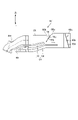
- FIG. 1 is a cross-sectional view showing a schematic configuration of an internal combustion engine according to one embodiment of the present invention
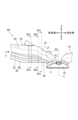
- FIG. FIG. 2 is a diagram showing a three-dimensional model of an intake system in the internal combustion engine of FIG. 1
- FIG. 2 is a cross-sectional view of a portion of the main flow path and the upstream end side portion of the main partition in the internal combustion engine of FIG. 1 ; It is the figure which looked at a part of main flow path shown in FIG. 3 from the upstream.
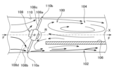
- FIG. 2 is a three-dimensional model of an intake system in the internal combustion engine of FIG. 1 when a tumble valve, which is an intake control valve, is closed and a throttle valve is opened to a predetermined minute opening.
- FIG. 2 is a three-dimensional model of the intake system in the internal combustion engine of FIG. 1 when the tumble valve is closed and the throttle valve is opened to an opening larger than a predetermined minute opening.
- FIG. 2 is a three-dimensional model of the intake system in the internal combustion engine of FIG. 1, when both the tumble valve and the throttle valve are fully open;
- FIG. 2 is a view of a three-dimensional model of the internal combustion engine of FIG. 1 including a portion of the intake passage on the downstream side of the throttle valve and the downstream side of the tumble valve and the exhaust port, viewed in a direction perpendicular to the cylinder axis and the direction of intake air flow;
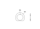
- FIG. 9 is a cross-sectional view of the three-dimensional model of FIG. 8 taken along line IXA-IXA;
- FIG. 9 is a cross-sectional view of the three-dimensional model of FIG. 8 along line IXB-IXB;
- FIG. 9 is a cross-sectional view of the three-dimensional model of FIG. 8 at a position along line IXC-IXC;
- FIG. 4 is a diagram for explaining the flow of intake air through a butterfly valve;
- FIG. 10 is a further diagram for explaining the flow of intake air by the butterfly valve;
- FIG. 2 is a diagram for explaining the flow of intake air around a throttle valve in the internal combustion engine of FIG. 1;
- FIG. 2 is a diagram showing simulation results of intake air flow around a throttle valve in the internal combustion engine of FIG. 1;
- FIG. 14 is a cross-sectional view of the intake passage along line XIVA-XIVA in the simulation model of FIG. 13;
- FIG. 14 is a cross-sectional view of the intake passage along line XIVB-XIVB in the simulation model of FIG. 13;
- FIG. 2 is a diagram showing a modification of the intake structure of the internal combustion engine of FIG. 1;
- FIG. 1 is a cross-sectional view of an internal combustion engine 10 along an axis (cylinder axis) C of a cylinder bore 12b of a cylinder block 12 of the internal combustion engine 10.
- FIG. 1 is a cross-sectional view of an internal combustion engine 10 along an axis (cylinder axis) C of a cylinder bore 12b of a cylinder block 12 of the internal combustion engine 10.
- a piston 15 that reciprocates in the cylinder bore 12b of the cylinder block 12 is connected to the crankpin of the crankshaft 17 of the crankcase portion 16 by a connecting rod 18.
- a combustion chamber 20 is formed between the top surface 15a of the piston 15 slidably fitted in the cylinder bore 12b of the cylinder block 12 and the combustion chamber ceiling surface 14a of the cylinder head 14 facing the top surface 15a.
- the internal combustion engine 10 employs a SOHC type two-valve system, and a valve mechanism 22 is provided in the cylinder head 14 .
- a cylinder head cover 24 is overlaid on the cylinder head 14 so as to cover the valve mechanism 22 .
- an endless cam chain (not shown) is provided on one side of the crankcase portion 16, the cylinder block 12, and the cylinder head 14 in the crankshaft direction.
- a camshaft 26 and a crankshaft 17 are installed through a cam chain chamber, and the camshaft 26 rotates in synchronism with the crankshaft 17 at a rotation speed of 1/2.
- a spark plug (not shown) is inserted into the combustion chamber 20 from the opposite side of the cam chain chamber (the other side in the crankshaft direction) of the cylinder head 14 .
- an intake port 32 and an exhaust port 34 are formed so as to extend while curving in directions vertically separating from each other.
- the upstream end of the intake port 32 opens toward the upper side of the cylinder head 14 and is connected to an inlet pipe 36 to form a continuous intake passage 38.
- a throttle body 40 is connected to the upstream side of the inlet pipe 36. be.
- the downstream end of the exhaust port 34 opens downward from the cylinder head 14 and is connected to the exhaust pipe 42 .
- An exhaust purification device and a silencer may be provided downstream of the exhaust pipe 42 .
- a cylindrical intake valve guide 44 is integrally fitted to the curved outer wall portion 32a of the intake port 32 in the cylinder head 14.
- An intake valve 46 slidably supported by an intake valve guide 44 opens and closes an intake valve port 28 of the intake port 32 facing the combustion chamber 20 .
- an exhaust valve 50 slidably supported by an exhaust valve guide 48 integrally fitted to the curved outer wall portion 34a of the exhaust port 34 in the cylinder head 14 is an exhaust valve opening facing the combustion chamber 20 of the exhaust port 34. Open and close 30.
- the intake valve 46 and the exhaust valve 50 are biased upward by valve springs so that the head portions 46a and 50a thereof close the intake valve port 28 and the exhaust valve port 30 facing the combustion chamber 20, respectively.
- Stem ends 46b and 50b of the intake valve 46 and the exhaust valve 50 are pushed down by an intake rocker arm 56 and an exhaust rocker arm 58 that contact and oscillate with the intake cam and the exhaust cam of the camshaft 26, and the intake valve 46 and the exhaust valve 50 are opened at a predetermined timing.
- the exhaust valve 50 opens, the intake port 32 communicates with the combustion chamber 20, and the exhaust port 34 communicates with the combustion chamber 20, and intake and exhaust are performed at predetermined timings.
- An inlet pipe 36 is connected to the upstream end of the intake port 32 of the internal combustion engine 10 via an insulator 60 to form a continuous intake passage 38.
- a throttle body 40 is connected to the upstream side of the inlet pipe 36. be done.
- the throttle body 40 has an intake passage 40a with a substantially circular cross section forming part of the intake passage 38 communicating with the combustion chamber 20 of the internal combustion engine 10, and the upstream side of the intake passage 40a is connected to an air cleaner device (not shown).
- the throttle body 40 is rotatably supported in the throttle body 40 by a valve shaft, that is, a throttle valve shaft 40b which intersects the direction of flow of intake air in the intake passage 40a, that is, at right angles to the central axis of the intake passage 40a. It has a throttle valve 40c that can variably control the flow area of the intake passage 40a to open and close the intake passage 40a.
- the throttle valve 40c is of the butterfly type, and has a throttle valve shaft 40b and a disk-shaped valve body 40d that is fixed to the throttle valve shaft 40b and rotates integrally with the throttle valve shaft 40b.
- the throttle valve 40c is rotatable clockwise in FIG. 1 in the valve opening direction by the driver's operation or the like. It is urged counterclockwise in the valve closing direction so as to be in the fully closed position in contact with the wall surface.
- the opening direction and the closing direction of the throttle valve 40c may be opposite to each other.
- the intake structure S is configured to give a tumble swirl flow of the fuel-air mixture in the combustion chamber 20 in order to obtain more favorable combustion in the combustion chamber 20, i.e., vertical rotation. ing. That is, the intake passage 38 is divided along the direction of intake air flow by a partition portion 62 leading from the inlet pipe 36 to the intake port 32, and is configured such that the passing intake air generates a tumble flow within the combustion chamber 20. It is partitioned into a tumble channel 64 and a main channel 66 excluding the tumble channel 64 .
- the tumble flow path 64 corresponds to the first intake passage, and the main flow path 66 corresponds to the second intake passage. Note that the tumble channel 64 may also be referred to as a secondary channel.
- a partition 72 is provided in the tumble flow path 64 so as to continue mainly from the inlet pipe 36 to the intake port 32 .
- the tumble flow path 64 is partitioned into two intake passages 68 and 70 .
- One of the two intake passages 68 , 70 is the first tumble passage 68 and the other of them is the second tumble passage 70 .
- the first tumble flow path 68 corresponds to the third intake passage
- the second tumble flow path 70 corresponds to the fourth intake passage.
- the partition 62 that separates the tumble flow channel 64 and the main flow channel 66 is referred to as a main partition
- the partition 72 that separates the first tumble flow channel 68 and the second tumble flow channel 70 of the tumble flow channel 64 is called a secondary partition. It is called a partition.
- the main partition 62 extends like a plate in the direction of flow of intake air
- the sub-partition 72 also extends like a plate along the direction of the flow of intake air, for example, substantially parallel to the main partition 62 .
- the main partition 62 is provided so as to substantially bisect the intake passage 38 in the vertical direction, here so as to substantially extend on the central axis extending in the flow direction.
- the sub-partition 72 is provided so as to substantially bisect the tumble flow path 64 in the vertical direction, here so as to substantially extend on the central axis of the tumble flow path 64 extending in the flow direction.
- a tumble flow path 64 and a main flow path 66 partitioned by the main partition 62 are formed in the intake passage 38, and a first tumble flow path 68 and a first A second tumble channel 70 is formed closer to the main channel 66 than the tumble channel 68, that is, positioned between the first tumble channel 68 and the main channel 66.
- the main partition 62 extends so as to substantially bisect the intake passage 38 in the vertical direction
- the secondary partition 72 extends so as to substantially bisect the tumble flow passage 64 in the vertical direction.
- the cross-sectional area of the main channel 66 is clearly greater than the cross-sectional area of the first tumble channel 68 and clearly greater than the cross-sectional area of the second tumble channel 70 . Therefore, naturally, the sum of the cross-sectional area of the main channel 66 and the cross-sectional area of the second tumble channel 70 is clearly larger than the cross-sectional area of the first tumble channel 68 .
- each of the main partition 62 and the sub-partition 72 may be provided so as to be biased, for example, in one of the vertical directions.
- the ratio (SA1:SA2) between the sum SA1 of the cross-sectional area of the main channel 66 and the cross-sectional area of the second tumble channel 70 and the cross-sectional area SA2 of the first tumble channel 68 is 8:2 to 7: It should be set to 3. However, the ratio is not limited to that range.
- the lower portion of the intake passage 38 partitioned by the main partition 62 forms the tumble flow channel 64
- the upper portion forms the main flow channel 66
- the lower portion of the tumble flow channel 64 partitioned by the secondary partition 72 forms the first tumble flow.
- Channel 68, the upper portion of which constitutes secondary tumble channel 70 is not limited herein to such a top-to-bottom arrangement.
- the terms "top” and “bottom” of the intake passage 38 and the like refer to the direction from the crankshaft 17 to the cylinder head 14 or the cylinder head cover 24 in the direction of the cylinder axis C.
- the direction opposite to this "upward” direction that is, the direction from the cylinder head 14 side to the crankshaft 17 side is called the “downward” or “downward” direction
- the absolute “upward” or “downward” direction in space does not mean
- the "up” or “up” direction corresponds to the first direction
- the "down” or “down” direction corresponds to the second direction.
- the relationship it is also possible for the relationship to be reversed so that the "up” or “up” direction corresponds to the second direction and the "down” or “down” direction corresponds to the first direction.
- the main partition 62 continuously extends from the throttle valve 40c to the intake port 32 in the intake air flow direction F at a first predetermined distance.
- the sub-partition 72 extends continuously from the throttle valve 40c to the intake port 32 at a second predetermined distance in the intake flow direction F.
- the upstream end 72a of the sub-partition 72 extends further upstream than the upstream end 62a of the main partition 62 in the flow direction F of the intake air.
- the upstream end 72a of the sub-partition 72 that is, the edge 72at thereof, is positioned upstream in the intake air flow direction F from the upstream end 62a of the main partition 62, that is, the edge 62at thereof.
- the upstream side of the sub-partition 72 extends to the connecting pipe 77 between the inlet pipe 36 and the throttle body 40 .
- the upstream side of the main partition 62 extends to the connecting pipe 77 between the inlet pipe 36 and the throttle body 40 .
- the main partition 62 and the sub-partition 72 may be formed without providing the connection pipe 77 .
- the downstream end 62b of the main partition 62 extends further downstream than the downstream end 72b of the sub-partition 72, and the downstream edge 62bt of the downstream end 62b is the downstream edge of the downstream end 72b in the intake air flow direction F. Located downstream of 72bt.
- valve shaft 40b of the throttle valve 40c is orthogonal to the intake flow direction F of the intake passage 40a of the intake passage .
- the vertical direction is parallel to the paper, and the valve shaft 40b of the throttle valve 40c is perpendicular to the paper. Therefore, the valve shaft 40b of the throttle valve 40c intersects the flow direction F of the intake air and intersects the vertical direction, for example, the first direction.
- the valve shaft 40b of the throttle valve 40c is perpendicular to the vertical direction, such as the first direction, and the intake air flow direction F of the intake passage .
- a tumble valve 76 is provided in the main flow passage 66. Although the tumble valve 76 is provided on the inlet pipe 36 here, it may be provided on the connection pipe 77 .
- the tumble valve 76 is rotatably supported in the inlet pipe 36 by a valve shaft 76b that intersects the main flow path 66 perpendicularly to the direction of intake air flow, i.e., perpendicular to the central axis of the main flow path 66, and opens and closes the main flow path 66. configured to be able to
- the tumble valve 76 is of the butterfly type, and has a valve shaft 76b and a substantially disk-shaped valve body 76c that is fixed to the valve shaft 76b and rotates integrally with the valve shaft 76b.
- the tumble valve 76 is configured with the valve body 76c, which is a single valve member that rotates integrally with the valve shaft 76b.
- the valve shaft 76b of the tumble valve 76 is parallel to the throttle valve shaft 40b here, it does not have to be parallel.
- the tumble valve 76 may also be called a tumble control valve, TCV, or the like, and corresponds to the intake control valve of the present invention.
- FIG. 2 shows a three-dimensional model M1 of the intake system of the internal combustion engine 10, particularly the intake system on the downstream side.
- FIG. 2 is a view of the three-dimensional model M1 from the left-right direction (perpendicular to the up-down direction), and is a view from the back side of the page of FIG.
- FIG. 2 is a view of the three-dimensional model M1 viewed from a direction orthogonal to the valve axis 46c of the intake valve 46 and orthogonal to the extending direction of the main partition 62 and the extending direction of the sub-partition 72.
- a throttle valve 40c and a tumble valve 76 are represented in the three-dimensional model M1.
- FIG. 3 shows a cross-sectional view of a portion of the main flow passage 66 and a portion of the main partition portion 62 on the upstream end 62a side, along the intake air flow direction. Further, FIG. 4 shows a view of part of the main flow path 66 shown in FIG. 3 as seen from the upstream side.
- the upstream end side of the main flow path 66 has a tapered portion 66a that tapers from the upstream side to the downstream side in the intake air flow direction.
- the tapered portion 66a is located between the upstream end 62a of the main partition portion 62 and the installation position of the tumble valve 76 in the main flow passage 66, and is a portion whose cross-sectional area decreases toward the downstream side in the intake flow direction.
- the upstream end 62a of the main partition 62 is thinnest on the side of the edge 62at and is formed so that the wall thickness increases toward the downstream side (see FIG. 3).
- the upstream side of the tapered portion 66a is substantially D-shaped as shown in FIG.
- a circular passage portion 66b having a substantially circular cross section is directly connected to the downstream side of the tapered portion 66a.
- the installation position of the tumble valve 76 which is an intake control valve capable of opening and closing the main flow passage 66, is determined in this circular passage portion 66b. Therefore, like the throttle valve 40c, the tumble valve 76 includes a disc-shaped valve body 76c fixed to the valve shaft 76b and integrally rotating therewith.
- the tumble valve 76 is selectively controlled to be fully open or fully closed by an ECU 80 described below, and its structure or configuration is simple.
- the tapered portion 66a and the circular passage portion 66b are formed in the connecting pipe 77, they may be formed in the inlet pipe .
- the internal combustion engine 10 is provided with fuel injection valves 78 and 79 .
- the fuel injection valve 78 is provided downstream of the throttle valve 40c and the tumble valve 76. As shown in FIG.
- the fuel injection valve 78 is provided in the inlet pipe 36 so as to face the main flow path 66 and is provided so as to inject fuel toward the intake port 32 . More specifically, fuel injection valve 78 is provided to inject fuel toward intake valve 46 via main flow path 66 .
- the fuel injection amount and injection timing from the fuel injection valve 78 are controlled in association with control of the throttle valve 40c and the tumble valve 76, respectively.
- Another fuel injection valve 79 is provided to inject fuel into the intake passage on the downstream side of the throttle valve 40c and the upstream side of the sub-partition portion 72.
- the amount of fuel injection from the fuel injection valve 79 and its injection timing are related to the amount of fuel injection from the fuel injection valve 78 and its injection timing, or the amount of fuel injection from the fuel injection valve 78 and its injection timing. can be controlled by
- An ECU (electronic control unit) 80 that controls the internal combustion engine 10 has a configuration as a so-called computer, and includes an intake control section 82 and a fuel injection control section 84 .
- the ECU 80 analyzes the operating state of the internal combustion engine 10 based on outputs from various sensors such as an engine rotation speed sensor and an engine load sensor, and controls the respective operations of the throttle valve 40c and the tumble valve 76 by the intake control unit 82. do.
- the throttle valve 40c can be opened to an arbitrary degree of opening by the ECU 80, and can be controlled to the degree of opening shown in FIGS.
- the ECU 80 controls each operation of the fuel injection valves 78 and 79 by means of the fuel injection control section 84 based on the analyzed operating state of the internal combustion engine 10 .
- the ECU 80 stores programs and various data for these controls.
- the ECU 80 substantially draws intake air from the tumble flow path 64, particularly from the first tumble flow path 68, more preferably only from the first tumble flow path 68.
- the tumble valve 76 is closed, and the throttle valve 40c is controlled to a predetermined small opening degree (see FIG. 5).
- the flow of intake air is promoted as schematically shown by the arrows in FIG. form a stream.
- the first tumble flow path 68 has a relatively small cross-sectional area, it is possible to increase the flow velocity even with an intake air amount suitable for a low load region, and to form a strong tumble flow.
- the ECU 80 when the operating state of the internal combustion engine 10 is in the medium load range, the ECU 80 operates the tumble valve 76 so that the intake air is taken in from the first tumble flow path 68 and the second tumble flow path 70, that is, the tumble flow path 64. It closes and controls the opening of the throttle valve 40c to be larger than a predetermined minute opening (see FIG. 6). At this time, the throttle valve 40c is controlled to have an opening degree smaller than that of full opening, but may be controlled to fully open. As a result, the flow of intake air is promoted as schematically shown by the arrows in FIG. A tumble flow is formed in the combustion chamber 20 .
- the intake air from the first and second tumble flow passages 68 and 70 forms the tumble flow, even in the medium load range where a larger amount of intake air is required than in the low load range, the necessary intake air amount is secured and strong A tumble flow can be formed.
- the fuel injection from the fuel injection valves 78 and 79 is controlled so that the air-fuel ratio becomes lean, but forming a tumble flow effectively can cause combustion.
- the ECU 80 causes the intake air to be taken in from the tumble flow path 64 including the first tumble flow path 68 and the second tumble flow path 70 and the main flow path 66.
- the tumble valve 76 is opened, here fully opened, and the throttle valve 40c is controlled to an opening larger than a predetermined small opening such as fully open (see FIG. 7).
- intake air flows as schematically shown by arrows in FIG. A tumble flow is preferably achieved in the chamber 20, otherwise a suitable in-cylinder flow velocity is achieved.
- the fuel injection from the fuel injection valves 78 and 79 is controlled so that the air-fuel ratio becomes stoichiometric, and a more suitable cylinder flow velocity is realized. Combustion can be caused more effectively.
- the tumble valve 76 is opened and the throttle valve 40c is opened to draw in intake air from the tumble flow path 64 and the main flow path 66.
- the intake structure S of the internal combustion engine 10 is designed to increase the amount of intake air by the intake air from the main flow path 66 and to more preferably secure the tumble performance by the intake air from the tumble flow path 64. It has further configurations and shapes. Further explanation is given below. Note that the following configuration, for example, the action and effect of the confluence portion 86, which enables more favorable tumble performance due to intake air from the tumble flow path 64, is established even when the tumble valve 76 is closed.
- a confluence portion 86 is formed on the downstream side of the tumble flow channel 64 .
- the confluence portion 86 is provided at a point where the first tumble flow path 68 and the second tumble flow path 70 merge on the downstream side thereof.
- the tumble flow path 64 joins the main flow path 66 via the confluence portion 86 .
- the confluence portion 86 is formed in the cylinder head 14 .
- the confluence portion 86 is formed as part of the intake port 32 .
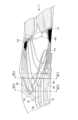
- FIG. 8 shows a three-dimensional model M2 including the portion of the intake passage 38 on the downstream side of the throttle valve 40c and the tumble valve 76 and the exhaust passage of the exhaust port 34.
- FIG. 8 is a view of the three-dimensional model M2 from a direction orthogonal to the cylinder axis C and orthogonal to the intake flow direction F.
- FIG. 9A A cross-sectional view of the solid model M2 along the line IXA-IXA in FIG. 8 is shown in FIG. 9A, and a cross-sectional view of the solid model M2 along the line IXB-IXB in FIG. 8 is shown in FIG.
- FIG. 9C A cross-sectional view of the solid model M2 at a position along line IXC-IXC of 8 is shown in FIG. 9C.
- Line IXA-IXA in FIG. 8 passes near the upstream end of intake port 32, line IXB-IXB in FIG. passes near the downstream edge of All of these lines IXA-IXA to IXC-IXC are parallel to the cylinder axis C in FIG.
- the first tumble channel 68 and the second tumble channel 70 have generally the same shape and size.
- each of the first tumble flow path 68 and the second tumble flow path 70 smoothly extends from the upstream side to the downstream side without significantly changing its shape or size in the intake air flow direction.
- the first tumble flow path 68 and the second tumble flow path 70 are connected to the confluence portion 86 .
- the confluence portion 86 is connected to the main flow path 66 downstream of the downstream edge 62bt of the downstream end 62b of the main partition 62 (see FIGS. 1 and 8).
- the first tumble flow path 68 and the second tumble flow path 70 enter the main flow path 66 via the edge of the downstream end 72b of the sub-partition portion 72, that is, the confluence portion 86 downstream of the downstream edge 72bt. will be connected. Therefore, the intake air passing through the first tumble flow path 68 and the second tumble flow path 70 of the tumble flow path 64 can have strong directivity.
- the line L1 defined to extend in the intake flow direction at the confluence portion 86 intersects the cylinder axis C at an angle ⁇ 1 close to a right angle.
- line L2 intersects the cylinder axis C at an angle .theta.2 smaller than the angle .theta.1.
- the confluence portion 86 is partitioned so that the intake air from the tumble flow passage 64 via the confluence portion 86 flows into the combustion chamber 20 at a smaller entrance angle than the intake air from the main flow passage 66.
- the intake air passing through the tumble flow path 64 can be introduced into the combustion chamber 20 while maintaining strong directivity, and a strong tumble flow can be generated in the combustion chamber 20, for example.
- advance angle refers to the angle at which the intake air flowing into the combustion chamber 20 flows into the combustion chamber 20.
- the tumble channel 64 is defined to have a downwardly convex curved shape
- the main channel 66 is defined to have an upwardly convex curved shape. formed.
- FIG. 9B shows that the first tumble flow path 68 and the second tumble flow path 70 communicate with the upstream end of the confluence portion 86 .
- FIG. 1 shows one side TA1 of the cross section in the imaginary plane.
- the side TA1 of the upstream end 86u of the merging portion 86 is longer than the vertical length of the cross section 68A of the first tumble flow channel 68 and the vertical length of the cross section 70A of the second tumble flow channel 70, respectively. is clearly long.
- the cross-sectional area of each of the first tumble flow path 68 and the second tumble flow path 70 areas S1 and S2 in FIG.
- the intake air from the first tumble flow path 68 and the intake air from the second tumble flow path 70 can preferably flow into the confluence portion 86 . More specifically, when intake air flows through the first tumble flow path 68 and the second tumble flow path 70, the cross-sectional area of the confluence portion 86 is the cross-sectional area of the first tumble flow path 68 and the second tumble flow path 70, respectively. Since it is larger, the amount of intake air is less likely to be restricted at the merging portion 86, and an amount of intake air suitable for the operating range of the middle load range, for example, can be ensured.
- side TA2 in FIG. 9C is shorter than side TA1 in FIG. 9B. That is, toward the downstream side, the cross-sectional area of the confluence portion 86 of the tumble flow channel 64 tends to be smaller at the cross-sectional location in FIG. 9C than at the side TA1 in FIG. 9B, for example.
- the confluence portion 86 is sectioned so as to generally taper from the upstream end portion of the confluence portion 86 toward the downstream side.
- the upstream end 86u of the merging portion 86 is larger than the sum of the cross-sectional areas of the first tumble flow path 68 and the second tumble flow path 70 (for example, the sum of the area S1 of the cross section 68A and the area S2 of the cross section 70A).
- the area (cross-sectional area) in the cross section orthogonal to the flow direction on the downstream side becomes smaller.
- the intake air from the tumble channel 64 can flow into the combustion chamber 20 at a high flow velocity and preferably form a tumble flow.
- the cross-sectional area perpendicular to the flow direction on the downstream side of the upstream end of the confluence portion 86 cannot be made smaller than the sum of the cross-sectional areas of the first tumble flow channel 68 and the second tumble flow channel 70. , may be realized by means other than tapering.
- the other end half 40g is positioned downstream in the intake air flow direction F with respect to the valve shaft 40b, and is at an obtuse angle with the corresponding inner wall surface 38a downstream of the other end half 40g. form ⁇ . 5, the valve body 40d of the throttle valve 40c is inclined, so that the first gap G1 is wider than the second gap G2 in the intake air flow direction F. Located upstream.
- Each of the first gap G1 and the second gap G2 has a gap width equal to or less than the thickness of the main partition 62.
- the thickness of the main partition 62 is preferably the average thickness of the main partition 62 extending in the intake air flow direction.
- each of the first gap G1 and the second gap G2 preferably has a gap width of 3 mm or less (0 ⁇ gap width ⁇ 3 mm), more preferably 2 mm or less (0 ⁇ gap width ⁇ 2 mm).
- the sub-partitions 72 are also formed to have approximately the same thickness as the main partitions 62 . That is, in the present embodiment, each of the first gap G1 and the second gap G2 has a gap width equal to or less than the thickness of the sub-partition 72 .
- the first gap G1 has a maximum width in FIGS. 1 and 3, and is formed so that the width of the gap becomes smaller as it progresses to the left and right (the direction perpendicular to the paper surface in FIGS. 1 and 3). Good.
- the second gap G2 has a maximum width in FIGS. 1 and 3, and is preferably formed so that the width of the gap decreases as it progresses to the left and right.
- the widths of the first gap G1 and the second gap G2 are not limited to these widths, and may be designed and formed so as to achieve the effects described below.
- FIG. 10 Note that the description similar to the description below based on FIGS. 10 and 11 is described in detail in JP-A-2019-23459.
- FIG. 10 when the intake passage 100 is provided with a partition portion 106 that separates the tumble flow passage 102 and the main flow passage 104, and the butterfly valve 108 is provided upstream of the partition portion 106, the butterfly valve 108 gradually opens.
- FIG. 4 is a diagram schematically showing the flow of intake air when the valve is open (when it is in a slightly open state).
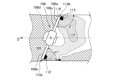
- FIG. 11 is a diagram mainly showing the pressure on the downstream side when the butterfly valve 108 shown in FIG. 10 is gradually opened.
- the butterfly valve 108 is rotatable in the clockwise direction R in FIG. 10 in the valve opening direction. It is biased counterclockwise in the valve closing direction so that the other end half body 108c, which rotates while abutting against the formed inner wall surface 110, is positioned at the fully closed position where it abuts against the same inner wall surface 110. As shown in FIG.
- One end side half 108b of the butterfly valve 108 in the fully closed state has an acute contact angle with the inner wall surface 110 of the intake passage 100 on the downstream side in the intake air flow direction F, and the other end side half 108c has an acute angle of contact with the intake air flow direction F.
- the contact angle of the inner wall surface 110 of the intake passage 100 on the downstream side in the direction F is an obtuse angle.
- the butterfly valve 108 is inclined, its one end half 108b is positioned upstream of the intake passage 100 with respect to the valve shaft 108d, and the other end half 108c of the butterfly valve 108 is Located downstream of the intake passage 100 .
- the angle ⁇ 1 between the one end half 108b of the butterfly valve 108 and the inner wall surface 110 of the intake passage 100 is an acute angle.
- the angle ⁇ 1 formed with the inner wall surface 110 is an obtuse angle.
- a strong negative pressure is generated in the region 112 immediately downstream of the obtuse angle side gap 110a and the acute angle side gap 110b (black area in FIG. 11), and the valve shaft 108d of the butterfly valve 108 is pushed.
- a wide negative pressure area 114 (dotted hatched area in FIG. 11) is generated in the downstream range of the butterfly valve 108 including. That is, as shown in FIG. 11, the portion of the intake passage 100 on the downstream side of the butterfly valve 108 is separated along the intake air flow direction F by the partition portion 106 having a surface substantially parallel to the valve shaft 108d of the butterfly valve 108.
- the channel 104 with the larger cross-sectional area is downstream of the other end half 108c, and the channel 102 with the smaller cross-sectional area is located downstream. If arranged on the downstream side of the one end side half 108b, when the butterfly valve 108 is gradually opened, the momentum of the intake air passing through the butterfly valve 108 and flowing toward the flow path 104 having a large cross-sectional area tends to weaken, and the momentum of the lost cross-sectional area decreases.
- the intake air flowing through the large flow path 104 is attracted by the negative pressure generated in the immediately downstream portions 112 (black portions in FIG.
- the channel 104 with a large cross-sectional area is used as the main channel, and the channel 102 with a small cross-sectional area is used as the tumble channel.
- the intake air that has once flowed into the main flow path 104 can be led to the tumble flow path 102 . That is, by setting the cross-sectional area of the main channel 104 to be larger than the cross-sectional area of the tumble channel 102, the intake air flowing through the tumble channel 102 can be strengthened.
- a first tumble channel 68 is located immediately downstream of one end half 40f of body 40d.
- the upstream end 72a of the sub-partitioning portion 72 extends further upstream than the upstream end 62a of the main partitioning portion 62.
- the sum of the cross-sectional area of the main channel 66 above the sub-partition 72 and the cross-sectional area of the second tumble channel 70 is the cross section of the first tumble channel 68 of the sub-partition 72.
- the throttle valve 40c is inclined when it is at a predetermined minute opening, and the one end side half of the throttle valve 40c located below the valve body 40d in the intake air flow direction F centering on the valve shaft 40b.
- the body 40f is located on the upstream side and forms an acute angle ⁇ with the corresponding wall surface on the downstream side thereof.
- An obtuse angle ⁇ is formed between the wall and its downstream side. Therefore, the butterfly valve 108, the tumble flow path 102, and the main flow path 104 of FIG. 70 can be mapped to Therefore, by opening the throttle valve 40c to a predetermined minute opening as described above, the intake structure S of the internal combustion engine of the present embodiment realizes the flow of intake air (see the arrow in FIG. 5) described based on FIG. can.
- the intake air that has passed through the second gap G2 can mainly flow to the main flow path 66 side, part or preferably all of it returns to the tumble flow path 64 side, together with the intake air that has passed through the first gap G1. , flow through the first tumble channel 68 .
- the intake air that has flowed downstream through the throttle valve 40c at a predetermined minute opening enters the first tumble flow path 68 and eventually flows into the tumble flow path 64 (see the arrow in FIG. 12).
- FIG. 14A shows the cross-sectional shape of the passage along line XIVA-XIVA in FIG. 13
- FIG. 14B shows the cross-sectional shape of the passage along line XIVB-XIVB in FIG.
- the position of FIG. 14A corresponds approximately to the position immediately upstream of the tapered portion 66a
- the position of FIG. 14B corresponds to the position of the circular passage portion 66b.
- the black portion is the portion where the pressure is the lowest, and occurred on the downstream side of the first gap G1 and the downstream side of the second gap G2.
- the intake air that has passed through the second gap G2 can move toward the main flow path 66 above the sub-partition 72 and the second tumble flow path 70 as indicated by the arrow FA, It flowed into the channel 68.
- the tumble flow path 64 including the first tumble flow path 68 and the second tumble flow path 70 and the main flow path 66 are formed. Therefore, by using one, a plurality, or all of them according to the operating state of the internal combustion engine, it is possible to secure the intake air amount according to the operating state.
- the valve shaft 40b of the throttle valve 40c intersects the vertical direction and the intake flow direction F of the intake passage 38, and the throttle valve 40c can be opened to a plurality of openings including a predetermined minute opening. Therefore, when the throttle valve 40c is opened to a predetermined minute opening, the first gap G1 formed between the throttle valve 40c and the intake passage wall surface 38c is located on the first tumble flow path 68 side, and the throttle valve The second gap G2 formed between 40c and the intake passage wall surface 38c is positioned on the main flow path 66 side. Furthermore, the upstream end 72a of the sub-partition 72 extends further upstream than the upstream end 62a of the main partition 62 in the intake flow direction F. As shown in FIG. Therefore, the intake air that has passed through the second gap G2 is urged toward the first tumble flow path 68 and is allowed to flow there. Therefore, tumble performance can be ensured.
- Such a reverse flow phenomenon when the throttle valve 40c is opened to a predetermined small degree of opening is established even when the tumble valve 76 is not provided.
- the tumble valve 76 is provided in the intake structure S of the internal combustion engine 10. allow the inspiratory air to flow to the As described above, the intake structure S of the internal combustion engine 10 configured as described above is provided with the tumble valve 76 for opening and closing the main flow path 66, but it is only opened fully open and fully closed, and its structure or configuration is not complicated. .
- the valve shaft 40b of the throttle valve 40c is orthogonal to the vertical direction and the intake flow direction F of the intake passage . Therefore, when the throttle valve 40c is opened to a predetermined minute opening, the first gap G1 can be preferably positioned on the first tumble flow path 68 side, and the second gap G2 can be positioned on the main flow path 66 side. be able to. Therefore, at that time, the flow of intake air to the first tumble flow path 68 through the second gap G2 can be encouraged more preferably.
- the cross section of the circular passage portion 66b of the main flow passage 66 at the installation position of the tumble valve 76 is substantially circular. Therefore, the degree of blockage of the main flow path 66 by the tumble valve 76 when the valve is closed can be increased more easily.
- the intake structure S includes the confluence portion 86 described above.
- the intake air when the throttle valve 40c is controlled to a predetermined minute opening, even if the intake air flows into the second tumble flow path 70, the intake air will flow through the first tumble flow path whose main purpose is to flow the intake air at that time. It joins the intake air of 68 at the junction 86 and is taken into the combustion chamber 20 . Therefore, at this time, the intake air from the tumble flow path 64 including the intake air flowing through the second tumble flow path 70 can be given a strong directivity, and the tumble flow in the combustion chamber 20 can be favorably strengthened. Tumble performance can be further secured.
- the number of sub-partitions is not limited to one, and may be plural.
- the tumble flow path 64 can be divided into a third intake passage corresponding to the first tumble flow passage 68 and a fourth intake passage corresponding to the second tumble flow passage 70. It becomes possible to divide into three or more intake passages, ie, intake passage sections, including the .
- the plurality of divided intake passage portions should preferably be connected to the main flow passage 66 via the confluence portion 86 and then to the combustion chamber 20, similar to the first and second tumble flow passages 68 and 70 described above. In this case, the plurality of sub-partitions may be provided in the tumble flow channel 64 separately from each other in the vertical direction.
- various members that define the intake passage of the internal combustion engine 10, particularly the intake passage on the downstream side of the throttle valve 40c, are preferably manufactured mainly by casting. As a result, it is possible to realize various shapes such as a downwardly convex tumble channel 64 and an upwardly convex main channel 66 . It should be noted that the present disclosure does not exclude the production of the member that defines the intake passage by a method other than casting.
- a resonator 90 is provided so as to communicate with the tumble flow path 64 .
- the resonator 90 communicates with the first tumble flow path 68 of the tumble flow paths 64 via a communication pipe 94 defining a communication path 92 .
- the resonator 90 may communicate with the second tumble channel 70 .
- the second tumble flow path is formed above the first tumble flow path, that is, on the first direction side, and the main stream is formed above the tumble flow path including these, that is, on the first direction side. made a road.
- the second tumble flow path may be formed below the first tumble flow path, and the main flow path may be provided below the tumble flow path including these.
- the throttle 40c should be turned upside down in the drawing corresponding to FIG.
- the present disclosure permits the inclination of the throttle valve 40c to be reversed vertically. Also in this case, the above effects described with reference to FIGS. 5 and 10 to 12 can be produced in the same manner.
- Tumble passage (first intake passage) 66...Main passage (second intake passage), 68...First tumble passage (third intake passage) 70...Second tumble flow path (fourth intake passage), 72...Partition (secondary partition) 76...Tumble valve (intake control valve), 86...Joining portion, 90...Resonator S...Intake structure, G1...First gap, G2...Second gap
Landscapes
- Engineering & Computer Science (AREA)
- Chemical & Material Sciences (AREA)
- Combustion & Propulsion (AREA)
- Mechanical Engineering (AREA)
- General Engineering & Computer Science (AREA)
- Cylinder Crankcases Of Internal Combustion Engines (AREA)
Abstract
La présente divulgation concerne une configuration, dans des moteurs à combustion interne conçus avec division du collecteur d'admission par des cloisons, qui permet, sans nécessiter de soupape de commande d'admission à structure complexe en plus de la soupape d'étranglement, à la fois : d'assurer un volume d'air aspiré selon les conditions de conduite ; et d'assurer un effet tourbillonnaire. Une structure S d'admission destinée à un moteur à combustion interne selon un mode de réalisation de la présente invention comporte : une cloison primaire (62), qui sépare un passage d'admission (38) du côté aval d'une soupape d'étranglement (40c) en un premier passage d'admission (64), servant de voie d'écoulement pour générer un écoulement tourbillonnaire, et en un deuxième passage d'admission (66) de son côté de première direction ; et une cloison secondaire (72), qui sépare le premier passage d'admission (64) en troisième passage d'admission (68) et quatrième passage d'admission (70) de son côté de première direction. La tige de soupape de la soupape d'étranglement coupe la première direction et la direction d'écoulement d'admission. L'extrémité amont de la cloison secondaire (72) dépasse, du côté amont, l'extrémité amont de la cloison primaire (62) selon la direction d'écoulement d'admission. La soupape d'étranglement est conçue pour permettre l'ouverture à une pluralité de degrés d'ouverture, en particulier à un degré prescrit d'ouverture infime.
Priority Applications (2)
| Application Number | Priority Date | Filing Date | Title |
|---|---|---|---|
| PCT/JP2021/036225 WO2023053378A1 (fr) | 2021-09-30 | 2021-09-30 | Structure d'admission d'air pour moteur à combustion interne |
| JP2023550939A JPWO2023053378A1 (fr) | 2021-09-30 | 2021-09-30 |
Applications Claiming Priority (1)
| Application Number | Priority Date | Filing Date | Title |
|---|---|---|---|
| PCT/JP2021/036225 WO2023053378A1 (fr) | 2021-09-30 | 2021-09-30 | Structure d'admission d'air pour moteur à combustion interne |
Publications (1)
| Publication Number | Publication Date |
|---|---|
| WO2023053378A1 true WO2023053378A1 (fr) | 2023-04-06 |
Family
ID=85781600
Family Applications (1)
| Application Number | Title | Priority Date | Filing Date |
|---|---|---|---|
| PCT/JP2021/036225 WO2023053378A1 (fr) | 2021-09-30 | 2021-09-30 | Structure d'admission d'air pour moteur à combustion interne |
Country Status (2)
| Country | Link |
|---|---|
| JP (1) | JPWO2023053378A1 (fr) |
| WO (1) | WO2023053378A1 (fr) |
Citations (6)
| Publication number | Priority date | Publication date | Assignee | Title |
|---|---|---|---|---|
| JPH09119317A (ja) * | 1995-10-27 | 1997-05-06 | Nissan Motor Co Ltd | 内燃機関の吸気制御装置 |
| JP2000291452A (ja) * | 1999-04-08 | 2000-10-17 | Aisan Ind Co Ltd | 内燃機関の吸気量制御装置 |
| JP2006077760A (ja) * | 2005-07-21 | 2006-03-23 | Nissan Motor Co Ltd | 内燃機関の吸気方法および吸気構造 |
| JP2011179427A (ja) * | 2010-03-02 | 2011-09-15 | Toyota Motor Corp | 内燃機関の燃焼制御装置 |
| WO2017154782A1 (fr) * | 2016-03-09 | 2017-09-14 | 本田技研工業株式会社 | Structure d'admission de moteur à combustion interne |
| JP2019023459A (ja) * | 2017-07-05 | 2019-02-14 | 本田技研工業株式会社 | 内燃機関の吸気構造 |
-
2021
- 2021-09-30 WO PCT/JP2021/036225 patent/WO2023053378A1/fr active Application Filing
- 2021-09-30 JP JP2023550939A patent/JPWO2023053378A1/ja active Pending
Patent Citations (6)
| Publication number | Priority date | Publication date | Assignee | Title |
|---|---|---|---|---|
| JPH09119317A (ja) * | 1995-10-27 | 1997-05-06 | Nissan Motor Co Ltd | 内燃機関の吸気制御装置 |
| JP2000291452A (ja) * | 1999-04-08 | 2000-10-17 | Aisan Ind Co Ltd | 内燃機関の吸気量制御装置 |
| JP2006077760A (ja) * | 2005-07-21 | 2006-03-23 | Nissan Motor Co Ltd | 内燃機関の吸気方法および吸気構造 |
| JP2011179427A (ja) * | 2010-03-02 | 2011-09-15 | Toyota Motor Corp | 内燃機関の燃焼制御装置 |
| WO2017154782A1 (fr) * | 2016-03-09 | 2017-09-14 | 本田技研工業株式会社 | Structure d'admission de moteur à combustion interne |
| JP2019023459A (ja) * | 2017-07-05 | 2019-02-14 | 本田技研工業株式会社 | 内燃機関の吸気構造 |
Also Published As
| Publication number | Publication date |
|---|---|
| JPWO2023053378A1 (fr) | 2023-04-06 |
Similar Documents
| Publication | Publication Date | Title |
|---|---|---|
| JP2639721B2 (ja) | 内燃機関の燃焼室 | |
| JP3494284B2 (ja) | 4ストロークサイクル内燃機関の吸気ポート構造 | |
| EP2947305B1 (fr) | Moteur à combustion interne à deux temps à balayage stratifié | |
| WO2022176862A1 (fr) | Structure d'admission d'air de moteur à combustion interne | |
| WO2023053378A1 (fr) | Structure d'admission d'air pour moteur à combustion interne | |
| JP4032906B2 (ja) | 多気筒エンジンの吸気装置 | |
| WO2023053377A1 (fr) | Structure d'admission d'air pour moteur à combustion interne | |
| JP6446085B2 (ja) | 隔壁プレート | |
| EP0234478A2 (fr) | Dispositif d'admission double pour moteur à combustion interne avec une paroi séparant un orifice à tourbillon et un canal de bypass | |
| JP7189683B2 (ja) | 内燃機関の吸気装置 | |
| JP7189681B2 (ja) | 内燃機関の吸気装置 | |
| JP4252670B2 (ja) | エンジンの吸気通路構造 | |
| WO2022176860A1 (fr) | Structure d'admission pour moteur à combustion interne | |
| WO2023188249A1 (fr) | Structure d'admission d'air pour moteur à combustion interne | |
| WO2024070901A1 (fr) | Structure d'admission pour moteur à combustion interne | |
| JPH10231729A (ja) | 内燃機関の吸気装置 | |
| WO2022210120A1 (fr) | Structure d'admission d'air pour moteur à combustion interne | |
| US20120222650A1 (en) | Throttle body configured to provide turbulent air flow to a combustion chamber of an engine, and engine including same | |
| WO2023053346A1 (fr) | Dispositif d'admission d'air pour moteur à combustion interne | |
| JP2697514B2 (ja) | 層状燃焼内燃機関の吸気ポート構造 | |
| JP3262380B2 (ja) | 層状燃焼内燃機関の吸気ポート構造 | |
| JP3329405B2 (ja) | 2バルブエンジンの吸気制御構造 | |
| JP3264749B2 (ja) | 2バルブエンジンの吸気制御構造 | |
| JP2717960B2 (ja) | エンジンの燃焼室 | |
| JPS597539Y2 (ja) | 複吸気式内燃機関 |
Legal Events
| Date | Code | Title | Description |
|---|---|---|---|
| 121 | Ep: the epo has been informed by wipo that ep was designated in this application |
Ref document number: 21959415 Country of ref document: EP Kind code of ref document: A1 |
|
| WWE | Wipo information: entry into national phase |
Ref document number: 2023550939 Country of ref document: JP |