WO2023047726A1 - アルカリ蓄電池用水素吸蔵合金 - Google Patents
アルカリ蓄電池用水素吸蔵合金 Download PDFInfo
- Publication number
- WO2023047726A1 WO2023047726A1 PCT/JP2022/024799 JP2022024799W WO2023047726A1 WO 2023047726 A1 WO2023047726 A1 WO 2023047726A1 JP 2022024799 W JP2022024799 W JP 2022024799W WO 2023047726 A1 WO2023047726 A1 WO 2023047726A1
- Authority
- WO
- WIPO (PCT)
- Prior art keywords
- hydrogen
- alloy
- storage alloy
- hydrogen storage
- mpa
- Prior art date
- Legal status (The legal status is an assumption and is not a legal conclusion. Google has not performed a legal analysis and makes no representation as to the accuracy of the status listed.)
- Ceased
Links
Images


Classifications
-
- C—CHEMISTRY; METALLURGY
- C22—METALLURGY; FERROUS OR NON-FERROUS ALLOYS; TREATMENT OF ALLOYS OR NON-FERROUS METALS
- C22C—ALLOYS
- C22C28/00—Alloys based on a metal not provided for in groups C22C5/00 - C22C27/00
-
- B—PERFORMING OPERATIONS; TRANSPORTING
- B22—CASTING; POWDER METALLURGY
- B22F—WORKING METALLIC POWDER; MANUFACTURE OF ARTICLES FROM METALLIC POWDER; MAKING METALLIC POWDER; APPARATUS OR DEVICES SPECIALLY ADAPTED FOR METALLIC POWDER
- B22F1/00—Metallic powder; Treatment of metallic powder, e.g. to facilitate working or to improve properties
-
- B—PERFORMING OPERATIONS; TRANSPORTING
- B22—CASTING; POWDER METALLURGY
- B22F—WORKING METALLIC POWDER; MANUFACTURE OF ARTICLES FROM METALLIC POWDER; MAKING METALLIC POWDER; APPARATUS OR DEVICES SPECIALLY ADAPTED FOR METALLIC POWDER
- B22F9/00—Making metallic powder or suspensions thereof
- B22F9/02—Making metallic powder or suspensions thereof using physical processes
- B22F9/04—Making metallic powder or suspensions thereof using physical processes starting from solid material, e.g. by crushing, grinding or milling
-
- C—CHEMISTRY; METALLURGY
- C22—METALLURGY; FERROUS OR NON-FERROUS ALLOYS; TREATMENT OF ALLOYS OR NON-FERROUS METALS
- C22C—ALLOYS
- C22C19/00—Alloys based on nickel or cobalt
-
- C—CHEMISTRY; METALLURGY
- C22—METALLURGY; FERROUS OR NON-FERROUS ALLOYS; TREATMENT OF ALLOYS OR NON-FERROUS METALS
- C22C—ALLOYS
- C22C19/00—Alloys based on nickel or cobalt
- C22C19/03—Alloys based on nickel or cobalt based on nickel
-
- C—CHEMISTRY; METALLURGY
- C22—METALLURGY; FERROUS OR NON-FERROUS ALLOYS; TREATMENT OF ALLOYS OR NON-FERROUS METALS
- C22F—CHANGING THE PHYSICAL STRUCTURE OF NON-FERROUS METALS AND NON-FERROUS ALLOYS
- C22F1/00—Changing the physical structure of non-ferrous metals or alloys by heat treatment or by hot or cold working
-
- C—CHEMISTRY; METALLURGY
- C22—METALLURGY; FERROUS OR NON-FERROUS ALLOYS; TREATMENT OF ALLOYS OR NON-FERROUS METALS
- C22F—CHANGING THE PHYSICAL STRUCTURE OF NON-FERROUS METALS AND NON-FERROUS ALLOYS
- C22F1/00—Changing the physical structure of non-ferrous metals or alloys by heat treatment or by hot or cold working
- C22F1/10—Changing the physical structure of non-ferrous metals or alloys by heat treatment or by hot or cold working of nickel or cobalt or alloys based thereon
-
- H—ELECTRICITY
- H01—ELECTRIC ELEMENTS
- H01M—PROCESSES OR MEANS, e.g. BATTERIES, FOR THE DIRECT CONVERSION OF CHEMICAL ENERGY INTO ELECTRICAL ENERGY
- H01M10/00—Secondary cells; Manufacture thereof
- H01M10/34—Gastight accumulators
- H01M10/345—Gastight metal hydride accumulators
-
- H—ELECTRICITY
- H01—ELECTRIC ELEMENTS
- H01M—PROCESSES OR MEANS, e.g. BATTERIES, FOR THE DIRECT CONVERSION OF CHEMICAL ENERGY INTO ELECTRICAL ENERGY
- H01M4/00—Electrodes
- H01M4/02—Electrodes composed of, or comprising, active material
- H01M4/24—Electrodes for alkaline accumulators
- H01M4/242—Hydrogen storage electrodes
-
- H—ELECTRICITY
- H01—ELECTRIC ELEMENTS
- H01M—PROCESSES OR MEANS, e.g. BATTERIES, FOR THE DIRECT CONVERSION OF CHEMICAL ENERGY INTO ELECTRICAL ENERGY
- H01M4/00—Electrodes
- H01M4/02—Electrodes composed of, or comprising, active material
- H01M4/36—Selection of substances as active materials, active masses, active liquids
- H01M4/38—Selection of substances as active materials, active masses, active liquids of elements or alloys
-
- H—ELECTRICITY
- H01—ELECTRIC ELEMENTS
- H01M—PROCESSES OR MEANS, e.g. BATTERIES, FOR THE DIRECT CONVERSION OF CHEMICAL ENERGY INTO ELECTRICAL ENERGY
- H01M4/00—Electrodes
- H01M4/02—Electrodes composed of, or comprising, active material
- H01M4/36—Selection of substances as active materials, active masses, active liquids
- H01M4/38—Selection of substances as active materials, active masses, active liquids of elements or alloys
- H01M4/383—Hydrogen absorbing alloys
-
- C—CHEMISTRY; METALLURGY
- C22—METALLURGY; FERROUS OR NON-FERROUS ALLOYS; TREATMENT OF ALLOYS OR NON-FERROUS METALS
- C22C—ALLOYS
- C22C2202/00—Physical properties
- C22C2202/04—Hydrogen absorbing
-
- H—ELECTRICITY
- H01—ELECTRIC ELEMENTS
- H01M—PROCESSES OR MEANS, e.g. BATTERIES, FOR THE DIRECT CONVERSION OF CHEMICAL ENERGY INTO ELECTRICAL ENERGY
- H01M10/00—Secondary cells; Manufacture thereof
- H01M10/24—Alkaline accumulators
-
- Y—GENERAL TAGGING OF NEW TECHNOLOGICAL DEVELOPMENTS; GENERAL TAGGING OF CROSS-SECTIONAL TECHNOLOGIES SPANNING OVER SEVERAL SECTIONS OF THE IPC; TECHNICAL SUBJECTS COVERED BY FORMER USPC CROSS-REFERENCE ART COLLECTIONS [XRACs] AND DIGESTS
- Y02—TECHNOLOGIES OR APPLICATIONS FOR MITIGATION OR ADAPTATION AGAINST CLIMATE CHANGE
- Y02E—REDUCTION OF GREENHOUSE GAS [GHG] EMISSIONS, RELATED TO ENERGY GENERATION, TRANSMISSION OR DISTRIBUTION
- Y02E60/00—Enabling technologies; Technologies with a potential or indirect contribution to GHG emissions mitigation
- Y02E60/10—Energy storage using batteries
Definitions
- the present invention relates to a hydrogen storage alloy used for alkaline storage batteries.
- nickel-metal hydride secondary batteries have a higher capacity than nickel-cadmium batteries and do not contain harmful substances in terms of the environment.
- Alkaline storage batteries are mainly used for these applications.
- Patent Documents 1 and 2 propose a rare earth-Mg transition metal based hydrogen storage alloy containing Mg.
- Patent Document 3 proposes a method of increasing the operating voltage by using a hydrogen storage alloy with a high hydrogen equilibrium pressure.
- Patent Document 5 reports that an alkaline storage battery is provided which is inexpensive, has good discharge output characteristics, and is excellent in high-temperature durability.
- the hydrogen storage alloy negative electrode has a general formula (La x Ln y ) 1-z Mg z Ni t-u Tu (T: selected from Al, Co, Mn, Zn and Ln is at least one selected from rare earth elements other than La and Y, x>y, 0.09 ⁇ z ⁇ 0.14, 3.65 ⁇ t ⁇ 3.80, 0.05 ⁇ u ⁇ 0.25), including hexagonal (2H) A 5 B 19 -type structures, trigonal (3R) A 5 B 19 -type structures, and A 2 B 7 -type structures, and 2H
- the powder X-ray diffraction intensity peak of the A 5 B 19 type crystal structure of the system by Cu-K ⁇ rays is larger than that of the A 5 B 19 type crystal structure and the A 2 B 7 type structure of the 3R system. are doing.
- the composition has a general formula: A (4-w) B (1+w) C 19 (where A is one or more selected from rare earth elements including Y (yttrium)) element, B is a Mg element, C is one or more elements selected from the group consisting of Ni, Co, Mn and Al, and w is a number in the range of -0.1 to 0.8).
- Patent Document 7 discloses a hydrogen storage alloy composed of an A component composed of a rare earth element represented by Ln and magnesium, and a B component composed of an element containing at least nickel and aluminum,
- the alloy main phase of the alloy has an A 5 B 19 type structure and the general formula is Ln l-x Mg x Ni y-a-b Al a M b (wherein M is selected from Co, Mn, Zn at least one element represented by 0.1 ⁇ x ⁇ 0.2, 3.6 ⁇ y ⁇ 3.9, 0.1 ⁇ a ⁇ 0.2, 0 ⁇ b ⁇ 0.1),
- the rare earth element (Ln) consists of at most two elements including at least lanthanum (La), and the hydrogen storage equilibrium pressure (Pa) when the hydrogen storage amount H/M (atomic ratio) at 40° C. is 0.5 is 0.03 to 0.17 MPa.
- Ln 1-x Mg x Ni y A z (wherein Ln is at least one element selected from rare elements including Y and Ca, Zr and Ti) and A is at least one element selected from Co, Mn, V, Cr, Nb, Al, Ga, Zn, Sn, Cu, Si, P and B, and subscripts x, y and z are , 0.05 ⁇ x ⁇ 0.25, 0 ⁇ z ⁇ 1.5, 2.8 ⁇ y + z ⁇ 4.0), the above Ln contains 20 mol of Sm % or more is disclosed.
- ⁇ x + y + z ⁇ 3.8 is disclosed.
- Patent Document 10 describes a hydrogen storage alloy for alkaline storage batteries that is capable of having high output characteristics far exceeding the conventional range by examining the composition ratio of the A 2 B 7 structure and the A 5 B 19 structure. and reported to provide a manufacturing method thereof and an alkaline storage battery.
- a specific hydrogen-absorbing alloy for alkaline storage batteries contains, except for La, rare earth elements including Y, an element R selected from Group 4, and an element M consisting of at least one of Co, Mn, and Zn.
- the general formula is La ⁇ R 1- ⁇ - ⁇ Mg ⁇ Ni ⁇ - ⁇ - ⁇ Al ⁇ M ⁇ ( ⁇ , ⁇ , ⁇ , ⁇ are 0 ⁇ 0.5, 0.1 ⁇ ⁇ 0.2, 3.7 ⁇ ⁇ ⁇ 3.9, 0.1 ⁇ ⁇ ⁇ 0.3, 0 ⁇ ⁇ ⁇ 0.2), and the A 5 B 19 type structure is 40% in the crystal structure The above is disclosed.
- Patent Document 11 provides a hydrogen storage alloy for alkaline storage batteries excellent in high output characteristics and output stability, and a method for producing the same.
- a hydrogen storage alloy for alkaline storage batteries AB n at least one selected element, T: at least one element selected from Co, Mn, Zn, Al, z>0), and the stoichiometric ratio n is 3.5 to 3.8 , the ratio of La to Re (x/y) is 3.5 or less, has at least an A 5 B 19 type structure, and has an average C-axis length ⁇ of the crystal lattice of 30 to 41 ⁇ . ing.
- Patent Literature 12 aims to provide a hydrogen-absorbing alloy or the like capable of improving the cycle characteristics of a nickel-metal hydride storage battery. Specifically, it is a hydrogen storage alloy represented by the general formula La v Sm w M1 x M2 y M3 z , wherein M1 is an element of Pr and/or Nd, and M2 is at least Mg among Mg and Ca.
- M3 is Ni or part of Ni selected from the group consisting of Group 6A elements, Group 7A elements, Group 8 elements (excluding Ni and Pd), Group 1B elements, Group 2B elements, and Group 3B elements is substituted with one or two or more elements, and v, w, x, y and z are the following formulas (1), (2) and (3) 3.2 ⁇ z/(v+w+x+y) ⁇ 3.7 Formula (1) 0.60 ⁇ v/(v+w+x) ⁇ 0.85 Formula (2) 0.01 ⁇ w/(v+w+x) ⁇ 0.06 Formula (3) A hydrogen storage alloy is disclosed that satisfies the following:
- the composition formula is La x Re y Mg 1-x-y Ni n-m-v Al m T v (where Re is at least one selected from rare earth elements including Y (excluding La)).
- seed element, T is at least one element selected from Co, Mn, Zn, Fe, Pb, Cu, Sn, Si, B, 0.17 ⁇ x ⁇ 0.64, 3.5 ⁇ n ⁇ 3 .8, 0.10 ⁇ m + v ⁇ 0.22, v ⁇ 0)
- the main phase has an A 5 B 19 type structure
- the concentration ratio of aluminum (Al) to nickel (Ni) in the surface layer is X
- the ratio X/Y between Al/Ni) (%) and the concentration ratio Y (Al/Ni) (%) of aluminum (Al) to nickel (Ni) in the bulk layer is 0.36 or more and 0.84 or less (0.84 or less). 36 ⁇ X/Y ⁇ 0.84) is disclosed.
- the composition formula is La x Re y Mg 1-x-y Ni n-m-v Al m T v (where Re is at least one element selected from rare earth elements including Y (excluding La)).
- Species element, T is at least one element selected from Co, Mn, Zn, 0.17 ⁇ x ⁇ 0.64, 3.5 ⁇ n ⁇ 3.8, 0.06 ⁇ m ⁇ 0.22 , v ⁇ 0)
- the crystal structure of the main phase is the A 5 B 19 type structure
- the ratio X/Y of the concentration ratio Y (Al/Ni) (%) of aluminum (Al) to nickel (Ni) in the layer is 0.36 or more and 0.85 or less (0.36 ⁇ X/Y ⁇ 0.85 ) is disclosed as a hydrogen storage alloy for alkaline storage batteries.
- the negative electrode of a nickel-hydrogen secondary battery has a general formula: (RE 1-x T x ) 1-y Mg y Ni z-a Al a (wherein RE is Y, Sc and rare earth at least one element selected from elements, T is at least one element selected from Zr, V and Ca, subscripts x, y, z, and a are 0 ⁇ x, 0.05 ⁇ y ⁇ 0.35, respectively , 2.8 ⁇ z ⁇ 3.9, 0.10 ⁇ a ⁇ 0.25), and a crystal structure in which AB 2 type subunits and AB 5 type subunits are laminated and a nickel-hydrogen secondary battery containing a hydrogen storage alloy in which a portion of the Ni is replaced with Cr.
- Non-Patent Document 1 has a chapter on the effect of Ce on an RE--Mg--Ni hydrogen storage alloy (RE: rare earth element).
- RE rare earth element
- La0.5Nd0.5 0.85Mg0.15Ni3.3Al0.2 _ _
- La0.45Nd0.45Ce0.1 0.85Mg0.15Ni3.3Al0.2 _ _ _
- La0.4Nd0.4Ce0.2 0.85Mg0.15Ni3.3Al0.2 _ _ _
- La0.3Nd0.3Ce0.4 0.85Mg0.15Ni3.3Al0.2 _ _ alloy
- Non-Patent Document 2 reports the characteristics of a hydrogen storage alloy composed of La 0.78 Mg 0.22 Ni 3.67 Al 0.10 .
- Non-Patent Document 3 reports a hydrogen storage alloy composed of La 0.64 Sm 0.07 Nd 0.08 Mg 0.21 Ni 3.57 Al 0.10 heat-treated at 995° C. for 24 hours. .
- Non-Patent Document 4 reports the characteristics of an alloy composition consisting of La 0.63 Nd 0.16 Mg 0.21 Ni 3.53 Al 0.11 .
- JP-A-11-323469 WO 01/48841 JP-A-2005-32573 JP 2016-69692 A JP 2014-229593 A WO2007/018292 JP 2009-176712 A JP 2009-74164 A JP 2009-108379 A Japanese Patent Application Laid-Open No. 2008-300108 JP 2011-023337 A Japanese Unexamined Patent Application Publication No. 2011-21262 JP 2011-82129 A JP 2011-216467 A JP 2014-26844 A
- Patent Documents 1 and 2 have not been put into practical use for various purposes because the alloys have not been optimized.
- Patent Document 5 shows the structure of an appropriate crystal phase by X-ray diffraction intensity, but when the hydrogen equilibrium pressure (hydrogen storage amount (H / M) at 40 ° C. is 0.5) dissociation pressure) is too high, which may cause problems when used as a battery.
- Patent Document 6 In the case of the technology disclosed in Patent Document 6, it aims to achieve both high capacity and long cycle life characteristics, but the evaluation is made up to several tens of cycles, and the original life evaluation has not been achieved.
- Patent Document 8 is an alloy containing a relatively large amount of Sm, and although it uses elements that are cheaper than Pr and Nd, the material cost is still high, and good rate characteristics are obtained. However, it was not possible to provide a sufficient hydrogen storage alloy.
- Patent Document 9 is an alloy containing relatively large amounts of La and Sm, and although it mainly uses elements that are cheaper than Pr and Nd, it is still inexpensive and has excellent durability. A hydrogen storage alloy cannot be provided. Also, it was necessary to improve the rate characteristics. In particular, Zr is essential in the examples, and only a B/A ratio of 3.6 is disclosed. In addition, although the hydrogen equilibrium pressure, which has decreased due to the increase in La content, is supposed to be raised to a level usable in batteries, it is often insufficient to set an inexpensive La-rich composition.
- Patent Document 10 Although the technology disclosed in Patent Document 10 showed an improvement in output at low temperatures, it did not have sufficient intrinsic high capacity and cycle life characteristics.
- the alloy excludes La among the rare earth elements, and the alloy containing a large amount of Nd is expensive.
- Patent Document 11 aims at high output characteristics and output stability, but has not yet reached the essential high capacity and cycle life characteristics.
- the amount of La contained is relatively small, the alloy is relatively expensive, and an inexpensive alloy that can be put into practical use has been desired.
- Patent Document 12 aims to improve the cycle characteristics and focuses on the absorption performance of oxygen gas generated in the battery when the battery is in use. However, further high capacity and improved cycle characteristics were desired. . Moreover, the high cost of materials is also a big problem.
- Patent Document 13 controls the Al concentration ratio of the surface to the inside of the alloy by surface treatment to improve the battery output characteristics and output stability, but the basic cycle life characteristics Further improvement was required, and an improvement in rate characteristics was also required. Another problem is that the material cost is relatively high.
- Patent Document 14 The technique disclosed in Patent Document 14 is intended to stabilize the battery output by subjecting the surface to a predetermined range of the Al/Ni ratio compared to the inside of the alloy by surface treatment. It was necessary to improve the cycle characteristics. Another problem is that the material cost is relatively high.
- Patent Document 15 was aimed at suppressing self-discharge and improving cycle life characteristics, but it did not lead to improvement in rate characteristics, and further increase in capacity was necessary, and improvement in this point is desired. rice field. Moreover, there also existed the subject that material cost was high.
- Non-Patent Document 1 concludes that the Ce-containing rare earth-Mg-Ni alloy has a small amount of hydrogen absorption and desorption, and is easily pulverized by repeated hydrogen absorption and desorption, so that deterioration in batteries is large. has become clear.
- Non-Patent Document 2 Although a high discharge capacity was obtained, the capacity after 200 cycles decreased by about 20%, and it was necessary to improve the characteristics for practical use.
- Non-Patent Document 3 a high discharge capacity of 370 mAh / g is obtained, but a certain amount of expensive Nd is included, and the discharge capacity after 200 cycles is reduced by about 20%. was not sufficient, and further improvement in characteristics was required for practical use.
- Non-Patent Document 4 a high discharge capacity was obtained, but the discharge capacity after 200 cycles decreased by about 20%, and further improvement in characteristics was required for practical use.
- the present invention has been made in view of these problems of the prior art, and the rare earth-Mg-Ni alloy is inexpensive and has important characteristics as a battery, such as discharge capacity, cycle life and rate. It is an object of the present invention to provide a practical hydrogen storage alloy for an alkaline storage battery with well-balanced characteristics.
- a hydrogen storage alloy for the negative electrode of an alkaline storage battery a composition composed mainly of crystal phases of A 5 B 19 phase and A 2 B 7 phase and containing inexpensive Ce is used.
- the inventors have found that the use of an alloy having such a compound enables a well-balanced combination of discharge capacity characteristics, charge/discharge cycle life characteristics, and rate characteristics, leading to the completion of the present invention.
- the hydrogen storage alloy of the present invention is mainly composed of two crystal phases, A 5 B 19 phase and A 2 B 7 phase, specifically Pr 5 Co 19 type, Ce 5 Co 19 type, It is characterized by having a Ce 2 Ni 7 type and a Gd 2 Co 7 type and having a component composition represented by the following general formula (A).
- M, T and subscripts a, b, c, d, e and f in the above formula (A) are M: at least one selected from Al, Zn, Sn and Si, T: at least one selected from Cr, Mo and V; 0 ⁇ a ⁇ 0.10, 0 ⁇ b ⁇ 0.15, 0.08 ⁇ c ⁇ 0.24, 0.03 ⁇ e ⁇ 0.14, 0 ⁇ f ⁇ 0.05, 3.55 ⁇ d+e+f ⁇ 3.80 satisfy the conditions of
- the hydrogen storage alloy for alkaline storage batteries according to the present invention is (a) in the general formula (A), the conditions of 0.08 ⁇ c ⁇ 0.18 and 3.70 ⁇ d+e+f ⁇ 3.80 are satisfied; (B) In the general formula (A), M is Al, and 0 ⁇ a ⁇ 0.08, 0 ⁇ b ⁇ 0.08, 0.14 ⁇ c ⁇ 0.24, and 0.03 satisfying the condition ⁇ e ⁇ 0.10; (c) Hydrogen pressure (P0.5) is 0.02 MPa or more and 0.1 MPa or less when the hydrogen absorption amount (H/M) at 80° C. is 0.5 in the hydrogen absorption/desorption characteristics.
- H/M hydrogen storage capacity
- H hydrogen storage capacity
- M metal atoms
- B hydrogen storage alloy with a particle size adjusted to a range of 150 ⁇ m or more and 1 mm or less has a volume average particle size MV of 75 ⁇ m or more after repeated hydrogen absorption and desorption, and the hydrogen pressure is increased to 1 MPa at 80 ° C.
- H is the number of hydrogen atoms
- M is the number of metal atoms
- the ratio of the sum ( ⁇ ) of the diffraction intensity of the (107) plane based on the 2H structure of the A 2 B 7 phase and the (1010) plane based on the 3R structure of the A 2 B 7 phase is ⁇ / ⁇ ⁇ 1, (h) X-ray diffraction measurement using Cu-K ⁇ rays as an X-ray source, the (101) plane of the AB 5 phase for the diffraction intensity ( ⁇ ) of the strongest diffraction peak in the range of the diffraction angle 2 ⁇ of 40 to 45 °
- the ratio of the diffraction intensity ( ⁇ ) of is ⁇ / ⁇ ⁇ 0.08, etc. is considered to be a more preferable means of solving the problem.
- the hydrogen storage alloy for alkaline storage batteries of the present invention is excellent in discharge capacity, cycle life and rate characteristics, and nickel-metal hydride secondary batteries using it have high power density and excellent charge-discharge cycle life. Therefore, it has excellent discharge capacity characteristics and can be used for various purposes such as consumer use, industrial use, and vehicle use.
- FIG. 1 is a partially cutaway perspective view illustrating an alkaline storage battery using the hydrogen storage alloy of the present invention
- FIG. An example of the hydrogen absorption/desorption characteristics (PCT characteristics) of the hydrogen storage alloy according to the present invention is shown in terms of the relationship between the hydrogen absorption amount H/M and the hydrogen pressure.
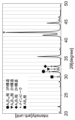
- P0.3. 4 is a graph showing an example of X-ray diffraction measurement results of the hydrogen storage alloy according to the present invention.
- FIG. 1 is a partially cutaway perspective view showing an example of a battery.
- the alkaline storage battery 10 includes a nickel positive electrode 1 whose main positive electrode active material is nickel hydroxide (Ni(OH) 2 ), a hydrogen storage alloy negative electrode 2 whose negative electrode active material is the hydrogen storage alloy (MH) according to the present invention,
- the storage battery includes an electrode group including a separator 3 and an electrolyte layer (not shown) filled with an alkaline electrolyte in a housing 4 .
- This battery 10 corresponds to a so-called nickel-metal hydride battery (Ni-MH battery), and the following reactions occur.
- the hydrogen storage alloy used for the negative electrode of the alkaline storage battery according to the first embodiment will be described below.
- the hydrogen storage alloy of the present embodiment is mainly composed of crystal phases of A 5 B 19 phase and A 2 B 7 phase, specifically Pr 5 Co 19 type, Ce 5 Co 19 type, Ce 2 Ni 7 type and Gd 2 Co 7 type, and have a component composition represented by the following general formula (A).
- M, T and subscripts a, b, c, d, e and f in the above formula (A) are M: at least one selected from Al, Zn, Sn and Si, T: at least one selected from Cr, Mo and V; 0 ⁇ a ⁇ 0.10, 0 ⁇ b ⁇ 0.15, 0.08 ⁇ c ⁇ 0.24, 0.03 ⁇ e ⁇ 0.14, 0 ⁇ f ⁇ 0.05, 3.55 ⁇ d+e+f ⁇ 3.80 satisfy the conditions of
- the alloy represented by the general formula (A) When the alloy represented by the general formula (A) is used as the negative electrode of an alkaline storage battery, it imparts high discharge capacity, cycle life and rate characteristics to the battery. contribute to the achievement of
- the hydrogen storage alloy of this embodiment contains a rare earth element as an element of the A component of the alloy mainly composed of the A 5 B 19 phase and the A 2 B 7 phase.
- a rare earth element two elements, La and Ce, are essential as basic components that provide hydrogen storage capacity.
- La and Ce have different atomic radii, the hydrogen equilibrium pressure can be controlled by this component ratio, and the equilibrium pressure required for the battery can be arbitrarily set.
- the atomic ratio a of Ce to the rare earth elements must be in the range of more than 0 and 0.10 or less.
- the Ce atomic ratio a value is preferably 0.005 or more and preferably 0.08 or less. A more preferable upper limit is 0.07.
- Sm can optionally be contained as a rare earth element other than La and Ce.
- Sm is an element that occupies a rare earth site as an element of the A component of an alloy mainly composed of A 5 B 19 phase and A 2 B 7 phase, and brings about hydrogen storage capacity like these elements. is an ingredient.
- Sm is less effective than Ce in raising the equilibrium pressure, but the durability is improved by substituting La with Ce.
- the upper limit of the b value which represents the atomic ratio of Sm in the rare earth element, is less than 0.15. Preferably, b ⁇ 0.12.
- a composition with a large amount of La has a high discharge capacity, and when combined with other elements, the discharge capacity characteristics are further improved.
- Pr and Nd as rare earth elements are not actively used, they may be contained at an unavoidable impurity level.
- Mg Mgc (where 0.08 ⁇ c ⁇ 0.24)
- Mg is an essential element in the present embodiment that constitutes the elements of the A component of the alloy mainly composed of the crystal phases of the A 5 B 19 phase and the A 2 B 7 phase, and improves the discharge capacity and cycle life characteristics. Contribute to improvement.
- the c value which represents the atomic ratio of Mg in the A component, is in the range of 0.08 or more and 0.24 or less. If the c value is less than 0.08, the hydrogen releasing ability is lowered, resulting in a decrease in the discharge capacity. On the other hand, if it exceeds 0.24, cracking especially accompanying hydrogen absorption/desorption is accelerated, and the cycle life characteristics, that is, the durability is lowered.
- the c value ranges from 0.09 to 0.235.
- Nid Ni is the main element of the B component of the alloy mainly composed of crystal phases of A 5 B 19 phase and A 2 B 7 phase. The atomic ratio d value will be described later.
- M M e (0.03 ⁇ e ⁇ 0.14)
- M is at least one selected from Al, Zn, Sn, and Si, and is an element contained as a B component element of an alloy mainly composed of A 5 B 19 phase and A 2 B 7 phase. It is effective for adjusting the hydrogen equilibrium pressure related to the battery voltage and can improve the corrosion resistance. It is effective in improving the durability of fine hydrogen storage alloy particles, that is, in cycle life characteristics. Al is particularly preferred.
- the e value which represents the atomic ratio of M to the A component, should be in the range of 0.03 or more and 0.14 or less. If the e-value is less than 0.03, corrosion resistance is not sufficient, resulting in insufficient cycle life. On the other hand, when the e-value exceeds 0.14, the discharge capacity decreases.
- a preferred e value is 0.04 or more and 0.12 or less. A more preferable upper limit is 0.095.
- T f (however, 0 ⁇ f ⁇ 0.05) T is at least one selected from Cr, Mo, and V, and, like the M element, is an element contained as an element of the B component of the alloy consisting of the A 5 B 19 phase and the A 2 B 7 phase.
- the inclusion of T is effective in adjusting the hydrogen equilibrium pressure related to the battery voltage, and the synergistic effect with the M element enhances corrosion resistance and durability. In particular, it is effective in improving the durability of fine grain hydrogen storage alloy, that is, in cycle life characteristics.
- the f value which represents the atomic ratio of T to the A component, should be 0.05 or less.
- f-value exceeds 0.05, excessive T element induces cracking due to absorption and desorption of hydrogen, resulting in deterioration of durability and insufficient cycle life.
- a preferable f value is in the range of 0.002 or more and 0.04 or less.
- the T elements Cr is particularly preferable from the viewpoint of durability.
- Ratio of A component and B component 3.55 ⁇ d + e + f ⁇ 3.80
- the stoichiometric ratio of the B component (Ni, M and T) to the A component of the alloy consisting of the A 5 B 19 phase and the A 2 B 7 phase, that is, the value of d + e + f represented by the general formula is 3.55 or more. It is preferably in the range of 3.80 or less. Below 3.55, the rate characteristics gradually deteriorate. On the other hand, when it exceeds 3.80, the AB 5 phase increases considerably, so the discharge capacity gradually decreases and cracking accompanying hydrogen absorption and release is promoted, resulting in a decrease in durability, that is, cycle life. end up It is preferably 3.56 or more and 3.79 or less.
- the hydrogen storage alloy of this embodiment has a hydrogen pressure when the hydrogen storage amount (H/M: atomic number ratio of hydrogen atoms (H) and metal atoms (M)) at the time of hydrogen release at 80° C. is 0.5.
- P0.5 hereinafter referred to as hydrogen equilibrium pressure
- H/M atomic number ratio of hydrogen atoms (H) and metal atoms (M)
- H/M atomic number ratio of hydrogen atoms (H) and metal atoms (M)
- M metal atoms
- the value of B1 is 0.92 or more and 2.98 or less.
- the discharge capacity is largely determined by the alloy composition.
- the durability depends on the degree of pulverization of the alloy due to hydrogen absorption and desorption, or the elution of the alloy components into the alkaline aqueous solution. This depends on the proportion of the alloy phase generated based on the alloy composition and heat treatment, and the properties of the alloy phase.
- a measurement holder of a PCT (Pressure-Composition-Temperature) evaluation device is filled with 7 g of a hydrogen-absorbing alloy and evacuated at 80 ° C. for 1 hour (0.01 MPa or less).
- Hydrogen absorption/desorption measurement (PCT characteristic evaluation) is performed in the pressure range of 0.01 to 3 MPa. After that, evacuate (0.01 MPa) for 1 hour, introduce hydrogen gas up to 3 MPa and hold for 1 hour to make the alloy absorb hydrogen almost completely, and evacuate (0.01 MPa) for 1 hour. Release hydrogen. Repeat this three times.
- hydrogen absorption/desorption measurement (PCT characteristic evaluation) is performed in the hydrogen pressure range of 0.01 to 3 MPa in the same manner as in the first cycle.
- the difference between the 1st and 5th hydrogen absorption/desorption and the 2nd to 4th hydrogen absorption/desorption is the processing time. short. After performing the hydrogen absorption/desorption cycle a total of five times in this way, the hydrogen absorption alloy powder is taken out and the particle size distribution is measured.
- the range of the volume average particle size MV after repeated hydrogen absorption/desorption is preferably 75 ⁇ m or more, more preferably 80 ⁇ m or more. Within this range, pulverization of the hydrogen-absorbing alloy does not proceed during charging and discharging when actually incorporated in a battery, and it is understood that durability is excellent in combination with good corrosion resistance in an alkaline solution. .
- the volume average particle diameter MV may be measured by a laser diffraction particle size distribution measuring device, and as a measuring device, for example MT3300EXII type manufactured by Microtrac Bell can be used.
- the index H/M of the hydrogen storage amount at 1 MPa obtained from PCT measurement at 80 ° C. is preferably 0.92 or more. More preferably, it is 0.93 or more. Within this range, it can be said that a hydrogen storage alloy having sufficient discharge capacity and high durability is obtained.
- the degree of elution of alloy components when a hydrogen storage alloy is immersed in an alkaline aqueous solution affects corrosion resistance, and as a result, an alloy with good durability is realized. Therefore, as a result of repeated evaluations under various conditions, the magnetization after immersion in an alkaline aqueous solution was measured for an alloy powder having a volume average particle size MV of about 35 ⁇ m, which was linked to corrosion resistance. Specifically, the obtained sample was immersed in a 7.15 mol/L potassium hydroxide aqueous solution at 80°C for 8 hours, washed and dried, and then measured at a temperature of 25°C and in a magnetic field using a vibrating sample magnetometer (VSM). The saturation magnetization was measured at 10 kOe, and it was found that an alloy with excellent durability was obtained when it was 60 emu/m 2 or less. It is preferably 55 emu/m 2 or less.
- VSM vibrating sample magnetometer
- the particle size distribution of the sample measured by VSM is measured, and the specific surface area ( m 2 /g), and the saturation magnetization per surface area (emu/m 2 ) is used as an evaluation criterion. This is to make the value of saturation magnetization less susceptible to the particle size distribution.
- the hydrogen storage alloy according to the present embodiment described above is an alloy whose main phase has an A 5 B 19 type crystal structure or an A 2 B 7 type crystal structure.
- the A 2 B 7 type crystal structure can be any of the hexagonal (2H) Ce 2 Ni 7 phase and the rhombohedral (3R) Gd 2 Co 7 phase coexisting.
- the former it is preferable that the former be included in a larger amount.
- the former is preferably contained in a larger amount, and A 2 B It is preferable that the combined amount of the 7- type crystal structure and the A 5 B 19 -type crystal structure is at least 70 mass % or more.
- the AB 3 type crystal structure (CeNi 3 phase which is a hexagonal system or PuNi 3 phase which is a rhombohedral system) may be contained as a subphase up to 5 mass%, but it is preferable that the amount is small, and most preferable. is not contained.
- the AB 2 type crystal structure (MgZn 2 phase) and the AB 5 type crystal structure (CaCu 5 phase) are not included in alkaline storage batteries from the viewpoint of discharge capacity and cycle life characteristics, but the characteristics may be contained to an extent that does not lower the , for example, about 5 mass% or less.
- the hydrogen storage alloy of the present embodiment has a (109) plane based on the 2H structure of the A 5 B 19 phase and a (1013) plane based on the 3R structure in X-ray diffraction measurement using Cu—K ⁇ rays as an X-ray source.
- the ratio of the sum ( ⁇ ) of the diffraction intensity of the (107) plane based on the 2H structure of the A 2 B 7 phase and the (1010) plane based on the 3R structure of the A 2 B 7 phase to the sum ( ⁇ ) of the diffraction intensity of the A 2 B 7 phase is ⁇ / ⁇ ⁇ 1 is preferably If the value of the ⁇ / ⁇ ratio exceeds 1, the above hydrogen equilibrium pressure becomes too high, which may make it difficult to use as a battery.
- the diffraction lines will be specifically described with the XRD graph of FIG.
- the peak indicated by ⁇ in the diffraction line is the diffraction line of the (1013) plane based on the 3R structure of the A 5 B 19 phase
- the peak indicated by ⁇ is the diffraction line of the (109) plane based on the 2H structure of the A 5 B 19 phase
- the peak indicated by ⁇ is the diffraction line of the (107) plane based on the 2H structure of the A 2 B 7 phase.
- the diffraction line of the (1010) plane based on the 3R structure of the A 2 B 7 phase does not appear, but it is usually seen at the diffraction angle between ⁇ and ⁇ .
- the hydrogen storage alloy of the present embodiment has an AB 5 phase with respect to the diffraction intensity ( ⁇ ) of the strongest diffraction peak in the range of diffraction angles 40 to 45 °. It is preferable that the ratio of the diffraction intensity ( ⁇ ) of the (101) plane of is ⁇ / ⁇ 0.08. If the .zeta./.epsilon. ratio exceeds 0.08, the cycle life characteristics may deteriorate. More preferably, it is 0.05 or less.
- the XRD graph in FIG. 3 shows the diffraction peak height ratio of the diffraction peak indicated by ⁇ to the strongest diffraction peak indicated by *.
- the X-ray diffraction measurement conditions are as follows. A powder pulverized to a particle size of less than 75 ⁇ m is set in a sample holder, the target is Cu, the tube voltage is 40 kV, the tube current is 40 mA, the scan speed is 0.5°/min, the scan step is 0.02°, and the divergence slit (DS) is 1. °, scattering slit (SS) 1°, no receiving slit (RS) and using only the k ⁇ filter.
- the hydrogen storage alloy for alkaline storage batteries preferably satisfies 0.08 ⁇ c ⁇ 0.18 and 3.70 ⁇ d+e+f ⁇ 3.80 in the general formula (A).
- the hydrogen storage alloy for alkaline storage batteries preferably satisfies 0.08 ⁇ c ⁇ 0.18 and 3.70 ⁇ d+e+f ⁇ 3.80 in the general formula (A).
- Mg Mgc (0.08 ⁇ c ⁇ 0.18)
- the upper limit of Mg is preferably limited to 0.18 in this embodiment. As a result, cycle life characteristics, ie, durability, are improved. More preferably, the c value is 0.09 or more and 0.17 or less.
- Ratio of A component and B component 3.70 ⁇ d + e + f ⁇ 3.80
- the stoichiometric ratio which is the molar ratio of the B components (Ni, M and T) to the A component, that is, the value of d + e + f represented by the general formula, is preferably limited to a lower limit of 3.70. .
- rate characteristics are improved.
- the amount of Ni on the alloy surface may have an effect. It is more preferably more than 3.70 and less than 3.80, still more preferably 3.705 or more and 3.79 or less.
- the ratio of Ce and Sm in the rare earth elements is reduced, the ratio of La is increased, the ratio of Mg is increased, and Al is used as the M element, and the ratio of Al is reduced.
- M is Al, 0 ⁇ a ⁇ 0.08, 0 ⁇ b ⁇ 0.08, 0.14 ⁇ c ⁇ 0.24, and 0.03 ⁇ e ⁇
- a hydrogen storage alloy for alkaline storage batteries that satisfies 0.10.
- Rare earth element La 1-ab Ce a Sm b (where 0 ⁇ a ⁇ 0.08, 0 ⁇ b ⁇ 0.08)
- cycle life characteristics are improved.
- Ce Like Ce, it improves cycle life characteristics.
- a composition with a large amount of La has a high discharge capacity, and when combined with other elements, the discharge capacity characteristics are further improved.
- Mg Mgc (0.14 ⁇ c ⁇ 0.24)
- the lower limit of Mg is preferably limited to 0.14 in this embodiment. Accordingly, the discharge capacity characteristics are improved. More preferably, the c value is 0.145 or more and 0.235 or less.
- M Me (where M is Al and 0.03 ⁇ e ⁇ 0.10)
- the atomic ratio of Al is preferably limited to less than 0.10. Accordingly, the discharge capacity characteristics are improved.
- a more preferable e value is 0.04 or more and 0.095 or less.
- the hydrogen storage alloy of the present embodiment includes rare earth elements (Ce, Sm, La, etc.), magnesium (Mg), nickel (Ni), aluminum (Al), zinc (Zn), silicon (Si), tin (Sn), After weighing metal elements such as chromium (Cr), molybdenum (Mo), and vanadium (V) so as to have a predetermined atomic ratio, they are put into an alumina crucible placed in a high-frequency induction furnace and placed in an inert gas atmosphere such as argon gas. After being melted below, it is cast into a mold to produce an ingot of the hydrogen storage alloy. Alternatively, a strip casting method may be used to directly prepare a flake-shaped sample with a thickness of about 200 to 500 ⁇ m.
- the hydrogen storage alloy of the present embodiment contains Mg with a low melting point and a high vapor pressure as a main component. It may be difficult to obtain alloys with the same chemical composition. Therefore, when manufacturing the hydrogen storage alloy of the present embodiment by the melting method, first, the alloy components other than Mg are melted, and then Mg raw materials such as metal Mg and Mg alloy are added to the melt. is preferred. In addition, this dissolving step is preferably performed in an inert gas atmosphere such as argon or helium. Specifically, the inert gas containing 80 vol% or more of argon gas is adjusted to 0.05 to 0.2 MPa. It is preferable to carry out under atmosphere.
- an inert gas atmosphere such as argon or helium. Specifically, the inert gas containing 80 vol% or more of argon gas is adjusted to 0.05 to 0.2 MPa. It is preferable to carry out under atmosphere.
- the alloy melted under the above conditions is then preferably cast in a water-cooled mold and solidified to form an ingot of the hydrogen storage alloy.
- the melting point (T m ) of each obtained ingot of the hydrogen storage alloy is measured using a DSC (differential scanning calorimeter).
- the hydrogen-absorbing alloy of the present embodiment is obtained by exposing the ingot after casting to an atmosphere of an inert gas such as argon or helium, nitrogen gas, or a mixed gas atmosphere thereof, to a melting point of 700° C. or higher. This is because it is preferable to perform heat treatment at a temperature of (T m ) or lower for 3 to 50 hours.
- a hydrogen storage alloy mainly composed of A 5 B 19 phase and A 2 B 7 phase can be produced. It can be confirmed by X-ray diffraction measurement using Cu—K ⁇ rays that the obtained hydrogen storage alloy is mainly A 5 B 19 phase and A 2 B 7 phase.
- the heat treatment temperature is preferably in the range of 750° C. to (T m ⁇ 30° C.). More preferably, it is in the range of 770°C to (T m -50°C).
- the holding time of the heat treatment is 2 hours or less, the ratio of the main phase cannot be stably increased to 50 vol% or more, and the homogenization of the chemical components of the main phase is insufficient, so hydrogen absorption and Expansion and contraction during release become non-uniform, increasing the amount of distortion and defects that occur, which may adversely affect cycle life characteristics.
- the holding time of the heat treatment is preferably 3 hours or longer, and more preferably 4 hours or longer from the viewpoint of homogenizing the main phase and improving the crystallinity.
- the holding time exceeds 50 hours, the amount of evaporation of Mg increases and the chemical composition changes, and as a result, there is a possibility that a large amount of AB 5 type subphase will be generated.
- the heat-treated alloy is pulverized by a dry method or a wet method.
- powder having an average particle size of 20 to 100 ⁇ m can be obtained by pulverizing using, for example, a hammer mill or ACM pulverizer.
- pulverizing by a wet method it is pulverized using a bead mill, an attritor, or the like.
- wet pulverization is preferable because it can be produced safely.
- the pulverized alloy particles may then be surface-treated by alkali treatment using an aqueous alkali solution such as KOH or NaOH, or acid treatment using an aqueous solution of nitric acid, sulfuric acid, or hydrochloric acid.
- a layer made of Ni is formed on at least a part of the surface of the alloy particles, and it is possible to suppress the progress of alloy corrosion and improve durability. Therefore, the cycle life characteristics of the battery and the discharge characteristics in a wide temperature range can be improved.
- acid treatment it is preferable to use hydrochloric acid because it is possible to precipitate Ni with less damage to the alloy surface.
- surface treatment can be performed at the same time.
- Example 1 No. 1 having the composition shown in Tables 1-1 to 1-3 below.
- An evaluation cell using a hydrogen storage alloy No. 1 to 57 as a negative electrode active material was produced in the manner described below, and an experiment was conducted to evaluate its characteristics.
- Alloys 1 to 37 are alloy examples (invention examples) that meet the conditions of the present invention.
- 38 to 57 are alloy examples (comparative examples) that do not satisfy the conditions of the present invention.
- No. of the comparative example. Alloy No. 38 was used as a reference alloy for evaluating cell properties.
- the measurement conditions were as follows: powder pulverized to a particle size of less than 75 ⁇ m was set in a sample holder, the target was Cu, tube voltage 40 kV, tube current 40 mA, scan speed 0.5°/min, scan step 0.02°, divergence slit (DS) 1°, scattering slit (SS) 1°, no receiving slit (RS) and using only a k ⁇ filter.
- the invention example No. It was confirmed that all of 1 to 37 are within the range of diffraction intensity ratio suitable for the present invention.
- Tables 2-1 to 2-3 The results are shown in Tables 2-1 to 2-3.
- Saturation magnetization measurement after immersion in an alkaline aqueous solution is performed according to the following procedure. First, 50 g of a 7.15 mol/L potassium hydroxide aqueous solution at 80° C. and 20 g of a hydrogen storage alloy adjusted to have a volume average diameter (MV) of 35 ⁇ m are placed in a glass beaker. Next, while stirring with a magnetic stirrer, the liquid temperature is maintained at 80° C. and immersed for 8 hours. After the passage of time, water washing is repeated until the pH of the washing water becomes 12 or less, followed by vacuum drying at 70° C. for 6 hours.
- MV volume average diameter
- PCT Characterization is performed in the following procedure.
- the hydrogen-absorbing alloy mass is pulverized, and the particle size is adjusted to 150 ⁇ m or more and 1 mm or less with a sieve in the same manner as described above.
- 3 MPa of hydrogen gas is pressurized and held for 3.5 hours to cause the hydrogen-absorbing alloy to absorb hydrogen.
- the alloy is evacuated for 1 hour to release hydrogen for activation treatment.
- hydrogen absorption/desorption measurement (PCT characteristic evaluation) is performed at a hydrogen pressure range of 0.01 to 1 MPa.
- ⁇ Positive electrode> Nickel hydroxide (Ni(OH) 2 ), metallic cobalt (Co) as a conductive agent, and two types of binders (styrene-butadiene rubber (SBR) and carboxymethyl cellulose (CMC)) are mixed at a mass ratio of Ni (OH) 2 :Co:SBR:CMC 95.5:2.0:2.0:0.5, and kneaded to form a paste composition.
- This paste composition was applied to porous nickel, dried at 80° C., and roll-pressed with a load of 15 kN to obtain a positive electrode.
- the electrolytic solution used was an alkaline aqueous solution obtained by mixing pure water with potassium hydroxide (KOH) to a concentration of 6 mol/L.
- KOH potassium hydroxide
- the discharge capacity of the electrode of the working electrode was confirmed by the following procedure. After performing constant current charging at a current value of 80 mA/g per active material of the working electrode for 10 hours, constant current discharging was performed at a current value of 40 mA/g per active material of the working electrode. The discharge termination condition was that the potential of the working electrode was -0.5V. The above charging and discharging were repeated 10 times, and the maximum discharge capacity was taken as the discharge capacity of the working electrode. It was confirmed that the discharge capacity of the working electrode was saturated and stabilized after 10 charge/discharge cycles. The measured discharge capacities are the alloy No. shown in Table 2-2. Using the discharge capacity of No.
- Discharge capacity (discharge capacity of evaluation alloy)/(discharge capacity of alloy No. 38) (C)
- Capacity retention rate (Discharge capacity at 500th cycle)/(Discharge capacity at 1st cycle) (D)
- the evaluation of cycle life characteristics was performed on the alloy No. shown in Table 1-2.
- the capacity retention rate of No. 38 after 500 cycles was defined as a reference capacity retention rate, and the ratio to it was calculated by the following formula (E).
- the cycle life characteristics were greater than those of No. 38 and evaluated as excellent.
- Cycle life characteristics (capacity retention rate of alloy No. 38 after 500 cycles)/(capacity retention rate of alloy No. 38 after 500 cycles) (E)
- the alloy cost is a relative evaluation of the raw material cost for manufacturing the alloy with the composition shown in Tables 1-1 to 1-3 by melting it from a metal with a purity of 99%, and Tables 2-1 to 2-3. It was shown to. No. 20% or more higher than the alloy No. 38 (standard cost) is marked with x, and those with the same cost to less than 20% higher than the alloy of No. 38 are marked with ⁇ . A less expensive alloy than the No. 38 alloy was marked with ⁇ .
- invention example No. Alloys 1 to 37 are alloy Nos. Compared to No. 38, the discharge capacity, the cycle life characteristics, the evaluation values of the rate characteristics, and the hydrogen equilibrium pressure are improved in a well-balanced manner, and it is clear that the cost is also advantageous.
- No. of the comparative example It can be seen that the alloys 38 to 57 are below the standard in any of the evaluation values of the properties, or the cost is ⁇ or ⁇ . If the equilibrium pressure is higher than the value within the range of the present invention, the ability to absorb the gas generated during charging will decrease, causing the battery to swell in a closed space, causing the safety valve to operate in some cases. As a result, the function as a battery cannot be maintained.
- the hydrogen storage alloy of the present invention is superior to the conventionally used AB 5 type hydrogen storage alloy in terms of discharge capacity, cycle life and rate characteristics, it is a negative electrode material for alkaline storage batteries for hybrid vehicles and idling stop vehicles. Not only is it suitable as a battery, but it can also be suitably used for alkaline storage batteries for electric vehicles.
Landscapes
- Chemical & Material Sciences (AREA)
- Engineering & Computer Science (AREA)
- Materials Engineering (AREA)
- Mechanical Engineering (AREA)
- Metallurgy (AREA)
- Organic Chemistry (AREA)
- General Chemical & Material Sciences (AREA)
- Chemical Kinetics & Catalysis (AREA)
- Electrochemistry (AREA)
- Physics & Mathematics (AREA)
- Thermal Sciences (AREA)
- Crystallography & Structural Chemistry (AREA)
- Manufacturing & Machinery (AREA)
- Battery Electrode And Active Subsutance (AREA)
Priority Applications (3)
| Application Number | Priority Date | Filing Date | Title |
|---|---|---|---|
| JP2023549371A JP7451000B2 (ja) | 2021-09-24 | 2022-06-22 | アルカリ蓄電池用水素吸蔵合金 |
| US18/692,720 US20250137104A1 (en) | 2021-09-24 | 2022-06-22 | Hydrogen absorbing alloy for alkaline storage battery |
| CN202280061961.6A CN117940595A (zh) | 2021-09-24 | 2022-06-22 | 碱蓄电池用氢吸留合金 |
Applications Claiming Priority (4)
| Application Number | Priority Date | Filing Date | Title |
|---|---|---|---|
| JP2021155922 | 2021-09-24 | ||
| JP2021-155922 | 2021-09-24 | ||
| JP2022-004557 | 2022-01-14 | ||
| JP2022004557 | 2022-01-14 |
Publications (1)
| Publication Number | Publication Date |
|---|---|
| WO2023047726A1 true WO2023047726A1 (ja) | 2023-03-30 |
Family
ID=85720435
Family Applications (1)
| Application Number | Title | Priority Date | Filing Date |
|---|---|---|---|
| PCT/JP2022/024799 Ceased WO2023047726A1 (ja) | 2021-09-24 | 2022-06-22 | アルカリ蓄電池用水素吸蔵合金 |
Country Status (3)
| Country | Link |
|---|---|
| US (1) | US20250137104A1 (https=) |
| JP (1) | JP7451000B2 (https=) |
| WO (1) | WO2023047726A1 (https=) |
Cited By (1)
| Publication number | Priority date | Publication date | Assignee | Title |
|---|---|---|---|---|
| WO2025074601A1 (ja) * | 2023-10-06 | 2025-04-10 | Fdk株式会社 | 水素吸蔵合金、この水素吸蔵合金を含む負極及びこの負極を含むニッケル水素二次電池 |
Citations (5)
| Publication number | Priority date | Publication date | Assignee | Title |
|---|---|---|---|---|
| WO2008018494A1 (fr) * | 2006-08-09 | 2008-02-14 | Gs Yuasa Corporation | Alliage d'accumulation d'hydrogène, électrode en alliage d'accumulation d'hydrogène, batterie d'accumulateurs, et procédé de fabrication d'un alliage d'accumulation d'hydrogène |
| JP2014229593A (ja) * | 2013-05-27 | 2014-12-08 | 三洋電機株式会社 | アルカリ蓄電池 |
| JP2016069692A (ja) * | 2014-09-30 | 2016-05-09 | 株式会社Gsユアサ | 水素吸蔵合金、電極及びニッケル水素蓄電池 |
| JP2017519901A (ja) * | 2014-05-14 | 2017-07-20 | ビーエーエスエフ コーポレーション | 水素吸蔵多相合金 |
| JP2022052729A (ja) * | 2020-09-23 | 2022-04-04 | 日本重化学工業株式会社 | アルカリ蓄電池用水素吸蔵合金 |
-
2022
- 2022-06-22 JP JP2023549371A patent/JP7451000B2/ja active Active
- 2022-06-22 US US18/692,720 patent/US20250137104A1/en active Pending
- 2022-06-22 WO PCT/JP2022/024799 patent/WO2023047726A1/ja not_active Ceased
Patent Citations (5)
| Publication number | Priority date | Publication date | Assignee | Title |
|---|---|---|---|---|
| WO2008018494A1 (fr) * | 2006-08-09 | 2008-02-14 | Gs Yuasa Corporation | Alliage d'accumulation d'hydrogène, électrode en alliage d'accumulation d'hydrogène, batterie d'accumulateurs, et procédé de fabrication d'un alliage d'accumulation d'hydrogène |
| JP2014229593A (ja) * | 2013-05-27 | 2014-12-08 | 三洋電機株式会社 | アルカリ蓄電池 |
| JP2017519901A (ja) * | 2014-05-14 | 2017-07-20 | ビーエーエスエフ コーポレーション | 水素吸蔵多相合金 |
| JP2016069692A (ja) * | 2014-09-30 | 2016-05-09 | 株式会社Gsユアサ | 水素吸蔵合金、電極及びニッケル水素蓄電池 |
| JP2022052729A (ja) * | 2020-09-23 | 2022-04-04 | 日本重化学工業株式会社 | アルカリ蓄電池用水素吸蔵合金 |
Cited By (1)
| Publication number | Priority date | Publication date | Assignee | Title |
|---|---|---|---|---|
| WO2025074601A1 (ja) * | 2023-10-06 | 2025-04-10 | Fdk株式会社 | 水素吸蔵合金、この水素吸蔵合金を含む負極及びこの負極を含むニッケル水素二次電池 |
Also Published As
| Publication number | Publication date |
|---|---|
| US20250137104A1 (en) | 2025-05-01 |
| JP7451000B2 (ja) | 2024-03-18 |
| JPWO2023047726A1 (https=) | 2023-03-30 |
Similar Documents
| Publication | Publication Date | Title |
|---|---|---|
| JP5718006B2 (ja) | 水素吸蔵合金およびニッケル水素二次電池 | |
| JP6276031B2 (ja) | 水素吸蔵合金粉末、負極およびニッケル水素二次電池 | |
| JP7461655B2 (ja) | アルカリ蓄電池用水素吸蔵合金 | |
| JP7251864B2 (ja) | アルカリ蓄電池用水素吸蔵合金 | |
| JP3828922B2 (ja) | 低Co水素吸蔵合金 | |
| JP5681729B2 (ja) | 水素吸蔵合金粉末、負極及びニッケル水素二次電池 | |
| JP2007291474A (ja) | 水素吸蔵合金およびニッケル水素二次電池 | |
| JP7451000B2 (ja) | アルカリ蓄電池用水素吸蔵合金 | |
| JP3965209B2 (ja) | 低Co水素吸蔵合金 | |
| JP5825671B2 (ja) | 水素吸蔵合金及びこの水素吸蔵合金を用いたニッケル水素二次電池 | |
| US12024757B2 (en) | Hydrogen storage alloy for alkaline storage battery and alkaline storage battery using the same | |
| JP7158684B2 (ja) | アルカリ蓄電池用水素吸蔵合金およびそれを負極に用いたアルカリ蓄電池ならびに車両 | |
| JP7572056B2 (ja) | アルカリ蓄電池用水素吸蔵合金 | |
| US5753054A (en) | Hydrogen storage alloy and electrode therefrom | |
| US6309779B1 (en) | Hydrogen storage alloy electrode and method for manufacturing the same | |
| JP2024137734A (ja) | 水素吸蔵合金 | |
| JP2025018552A (ja) | アルカリ蓄電池用水素吸蔵合金 | |
| US12272819B2 (en) | Hydrogen storage alloy for alkaline storage battery, alkaline storage battery using the same as negative electrode, and vehicle | |
| CN117940595A (zh) | 碱蓄电池用氢吸留合金 | |
| JP7788709B2 (ja) | アルカリ蓄電池用水素吸蔵合金およびそれを負極に用いたアルカリ蓄電池ならびに車両 | |
| US20090061318A1 (en) | Hydrogen-absorbing alloy and nickel-metal hydride storage battery | |
| JP2006228536A (ja) | アルカリ蓄電池用水素吸蔵合金及びアルカリ蓄電池 | |
| JP2007254782A (ja) | アルカリ蓄電池用水素吸蔵合金及びアルカリ蓄電池 |
Legal Events
| Date | Code | Title | Description |
|---|---|---|---|
| 121 | Ep: the epo has been informed by wipo that ep was designated in this application |
Ref document number: 22872484 Country of ref document: EP Kind code of ref document: A1 |
|
| WWE | Wipo information: entry into national phase |
Ref document number: 2023549371 Country of ref document: JP |
|
| WWE | Wipo information: entry into national phase |
Ref document number: 202280061961.6 Country of ref document: CN |
|
| WWE | Wipo information: entry into national phase |
Ref document number: 18692720 Country of ref document: US |
|
| NENP | Non-entry into the national phase |
Ref country code: DE |
|
| 122 | Ep: pct application non-entry in european phase |
Ref document number: 22872484 Country of ref document: EP Kind code of ref document: A1 |
|
| WWP | Wipo information: published in national office |
Ref document number: 18692720 Country of ref document: US |