WO2023047630A1 - ロボット装置およびその制御方法 - Google Patents
ロボット装置およびその制御方法 Download PDFInfo
- Publication number
- WO2023047630A1 WO2023047630A1 PCT/JP2022/009196 JP2022009196W WO2023047630A1 WO 2023047630 A1 WO2023047630 A1 WO 2023047630A1 JP 2022009196 W JP2022009196 W JP 2022009196W WO 2023047630 A1 WO2023047630 A1 WO 2023047630A1
- Authority
- WO
- WIPO (PCT)
- Prior art keywords
- fingers
- pressure
- sensor
- hand
- detection area
- Prior art date
- Legal status (The legal status is an assumption and is not a legal conclusion. Google has not performed a legal analysis and makes no representation as to the accuracy of the status listed.)
- Ceased
Links
Images



Classifications
-
- B—PERFORMING OPERATIONS; TRANSPORTING
- B25—HAND TOOLS; PORTABLE POWER-DRIVEN TOOLS; MANIPULATORS
- B25J—MANIPULATORS; CHAMBERS PROVIDED WITH MANIPULATION DEVICES
- B25J13/00—Controls for manipulators
- B25J13/08—Controls for manipulators by means of sensing devices, e.g. viewing or touching devices
-
- B—PERFORMING OPERATIONS; TRANSPORTING
- B25—HAND TOOLS; PORTABLE POWER-DRIVEN TOOLS; MANIPULATORS
- B25J—MANIPULATORS; CHAMBERS PROVIDED WITH MANIPULATION DEVICES
- B25J13/00—Controls for manipulators
- B25J13/08—Controls for manipulators by means of sensing devices, e.g. viewing or touching devices
- B25J13/081—Touching devices, e.g. pressure-sensitive
- B25J13/084—Tactile sensors
-
- B—PERFORMING OPERATIONS; TRANSPORTING
- B25—HAND TOOLS; PORTABLE POWER-DRIVEN TOOLS; MANIPULATORS
- B25J—MANIPULATORS; CHAMBERS PROVIDED WITH MANIPULATION DEVICES
- B25J15/00—Gripping heads and other end effectors
- B25J15/0009—Gripping heads and other end effectors comprising multi-articulated fingers, e.g. resembling a human hand
-
- B—PERFORMING OPERATIONS; TRANSPORTING
- B25—HAND TOOLS; PORTABLE POWER-DRIVEN TOOLS; MANIPULATORS
- B25J—MANIPULATORS; CHAMBERS PROVIDED WITH MANIPULATION DEVICES
- B25J15/00—Gripping heads and other end effectors
- B25J15/08—Gripping heads and other end effectors having finger members
- B25J15/12—Gripping heads and other end effectors having finger members with flexible finger members
Definitions
- This technology relates to a robot device having a hand unit and a control method thereof.
- a robot hand picks up an object to be grasped (hereinafter also referred to as a work) placed on a workbench
- the robot hand is placed at a reference height position (hereinafter referred to as Z (also referred to as a position) must be accurately placed before starting the series of lowering and gripping operations.
- Z also referred to as a position
- a method of positioning to the Z position for example, there is a method of determining the Z position of the robot hand using a jig that fixes the work in exactly the same position each time. There is the problem that the work must be stopped during the re-fabrication and re-setting of the Z-position.
- Patent Document 1 in order to detect an appropriate Z position, a workpiece is detected based on the results of comparison between the workpiece's three-dimensional position/orientation data obtained using a two-dimensional laser displacement sensor and a workpiece's three-dimensional model. There has been proposed a method of recognizing the three-dimensional position/orientation Z position of the workpiece and lowering the manipulator from the Z direction with respect to the recognized workpiece to grip the workpiece.
- Patent Document 2 describes a first omnidirectional imaging device provided at the tip of a finger of a hand and a first omnidirectional imaging device provided at a position other than the tip of the finger of the hand.
- a second omnidirectional imaging device with a different imaging axis is provided, and a method for positioning a hand based on these first and second omnidirectional imaging devices is disclosed.
- Patent Document 1 since it is necessary to arrange various sensors such as a two-dimensional laser displacement sensor in the work environment, the work environment is fixed, making it difficult to change the layout, etc., and the space efficiency is also poor. be.
- the technique of Patent Document 2 has the problem that computational costs and latency increase because post-stage arithmetic processing such as image processing becomes complicated.
- the purpose of this technology is to provide a robot device and its control method that can appropriately grip a workpiece with a simple sensor configuration without being restricted by the work environment.
- a robot apparatus includes a hand section, a plurality of sensor sections, and a control device.
- the hand section has a plurality of fingers capable of gripping a workpiece.
- the plurality of sensor units are provided on each of the plurality of finger portions.
- the plurality of sensor units include a first detection area capable of detecting a pressure component parallel to a first axial direction, which is the gripping direction of the workpiece, and a second axial direction that intersects with the first axial direction. and a second detection region capable of detecting parallel pressure components.
- the control device is configured to generate a control command for controlling the hand section based on the outputs of the plurality of sensor sections.
- the motion of the hand is controlled based on the pressure components in each axial direction detected by the sensors provided on each finger, there is no restriction in the work environment. , the workpiece can be properly gripped with a simple sensor configuration.
- the plurality of finger portions may each have a flat or curved tip region positioned at the fingertip and a flat or curved gripping region for gripping the workpiece.
- the first detection regions are arranged in the tip regions of the plurality of fingers
- the second detection regions are arranged in the grip regions of the plurality of fingers.
- At least one of the plurality of finger portions may be configured to be rotatable around a third axis perpendicular to each of the first axis and the second axis.
- the plurality of sensor units may each be composed of a common sensor sheet having the first detection area and the second detection area in its plane.
- the sensor sheet includes a sensor electrode layer having a plurality of capacitive elements arranged in a matrix, a reference electrode layer connected to a reference potential, and a modification arranged between the sensor electrode layer and the reference electrode layer.
- the pressure sensor may comprise a pressure sensor having layers.
- the sensor sheet may have a pair of pressure sensors having the above configuration and a separation layer made of a viscoelastic material and arranged between the pair of pressure sensors.
- the control device may be configured to output a control command for controlling movement of the hand portion along the second axial direction based on the output of the second detection area.
- the control command may be a control command for stopping movement of the hand unit along the second axial direction.
- the control command may be a control command for changing the moving speed of the hand section along the second axial direction.
- the control device controls the pressure detected in the second detection area between the plurality of fingers when the pressure value detected in the second detection area in the plurality of fingers is equal to or greater than a predetermined threshold value. It may be configured to output a control command for controlling the posture of the hand unit so that the value difference is equal to or less than a predetermined value.
- the control device moves the plurality of fingers in the first axial direction while maintaining a state in which a difference in pressure value detected in the second detection region between the plurality of fingers is equal to or less than a predetermined value.
- the control device may be configured to output a control command to lift the hand when a pressure value detected in the first detection area between the plurality of fingers is equal to or greater than a predetermined threshold.
- control device moves one of the plurality of fingers along the first axis and the It may be configured to output a control command to rotate about a third axis orthogonal to each of the second axes.
- a control method for a robot apparatus includes a hand unit having a plurality of fingers capable of gripping a workpiece, and a first axis provided for each of the plurality of fingers and serving as a gripping direction of the workpiece.
- a plurality of sensors having a first detection region capable of detecting a pressure component parallel to the direction of the sensor and a second detection region capable of detecting a pressure component parallel to a second axial direction intersecting the first axial direction and a control device for controlling the operation of the hand unit based on the outputs of the plurality of sensor units, the control method comprising: moving the hand portion in the second axial direction; Movement of the hand portion along the second axial direction is controlled based on the output of the second detection area.
- the step of controlling movement of the hand may include stopping movement of the hand along the second axial direction.
- the step of controlling the movement of the hand may include changing the moving speed of the hand along the second axial direction.
- the pressure value detected in the second detection area between the plurality of fingers when the pressure value detected in the second detection area between the plurality of fingers is equal to or greater than a predetermined threshold value, the pressure value detected in the second detection area between the plurality of fingers is
- the attitude of the hand unit may be controlled so that the difference between the detected pressure values is equal to or less than a predetermined value.
- the method for controlling the robot apparatus includes moving the plurality of fingers to the first pressure while maintaining a state in which a difference in pressure value detected in the second detection region between the plurality of fingers is equal to or less than a predetermined value. may be moved along the axial direction of
- the hand section may be raised when the pressure value detected in the first detection area between the plurality of finger sections is equal to or greater than a predetermined threshold.
- control method of the robot device may be configured such that, when the pressure value detected in the first detection area between the plurality of fingers is equal to or greater than a predetermined threshold, one of the plurality of fingers is It may be rotated around a third axis orthogonal to each of the first axis and the second axis.
- FIG. 1 is a perspective view of a main part showing a robot device according to an embodiment of the present technology
- FIG. It is a schematic sectional side view which shows the cross-section of the sensor sheet
- It is a schematic plan view which shows the sensor electrode layer in the said sensor sheet.
- It is a principal part top view which shows one structural example of the sensing part in the said sensor sheet.
- FIG. 5 is a schematic side cross-sectional view showing another configuration example of the sensor section;
- FIG. 4 is a front view of a main portion of a hand section showing an example of arrangement of a sensor section with respect to a finger section in the robot apparatus; It is explanatory drawing of the pressure detection surface of the said sensor part.
- FIG. 4 is a front view of a main part showing a procedure of one operation example of the robot device;
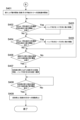
- FIG. 11 is a flow chart showing an example of a processing procedure of a control device that executes the operation of FIG. 10;
- FIG. 11 is a flow chart showing an example of a processing procedure of a control device that executes the operation of FIG. 10;
- FIG. 14 is a flow chart showing an example of a processing procedure of a control device that executes the operation of FIG. 13;
- FIG. 14 is a flow chart showing an example of a processing procedure of a control device that executes the operation of FIG. 13;
- FIG. 4 is a front view of a main part showing a procedure of one operation example of the robot apparatus
- FIG. 17 is a flow chart showing an example of a processing procedure of a control device that executes the operation of FIG. 16
- FIG. 11 is a schematic front view of a main portion showing another configuration example of the hand portion of the robot device;
- FIG. 1 is a perspective view of main parts showing a robot device 10 according to an embodiment of the present technology.
- the robot device 10 constitutes a robot hand.
- the configuration of the robot apparatus 10 will be briefly described below.
- the robot device 10 has an arm portion 1, a wrist portion 2 and a hand portion 3. As shown in FIG. 1, the robot device 10 has an arm portion 1, a wrist portion 2 and a hand portion 3. As shown in FIG.
- the arm portion 1 has a plurality of joint portions 1a, and the hand portion 3 can be moved to any position by driving the joint portions 1a.
- the wrist part 2 is rotatably connected to the arm part 1, and the hand part 3 can be rotated by its rotation.
- the hand part 3 has a plurality of finger parts capable of gripping an object (workpiece) to be gripped.
- the hand portion 3 has two fingers 3a and 3b facing each other, and the work is moved between the two fingers 3a and 3b by driving the two fingers 3a and 3b. It is possible to grasp. Note that the number of fingers can be appropriately changed, such as three or four or more.
- Sensor portions 20a and 20b are provided on the surfaces of the two finger portions 3a and 3b facing each other, respectively.
- the sensor units 20a and 20b have pressure detection surfaces and are configured to be capable of detecting pressure components applied in the direction perpendicular to the pressure detection surfaces and their in-plane distribution.
- the sensor units 20a and 20b may be triaxial sensors capable of detecting not only the pressure distribution but also the shear force parallel to the pressure detection surface and its in-plane distribution. The configuration of the sensor units 20a and 20b will be described later with reference to FIG. 2 and the like.
- the robot device 10 is driven under the control of the controller 11.
- the controller 11 includes a control section, a storage section, and the like.
- the control section is, for example, a CPU (Central Processing Unit), and controls driving of each section in the robot apparatus 10 based on a program stored in the storage section.
- the controller 11 may be a device dedicated to the robot device 10, or may be a general-purpose device.
- the controller 11 may be, for example, a PC (Personal Computer) connected to the robot device 10 by wire or wirelessly, a server device on a network, or the like. Controller 11 may be configured as part of robotic device 10 .
- the sensor units 20a and 20b have the same configuration.
- the sensor portions 20a and 20b are composed of sensor sheets capable of detecting the pressure distribution on the pressure detection surface as described above.
- FIG. 2 is a schematic side cross-sectional view showing a cross-sectional structure of a sensor sheet 210, which is one structural example of the sensor portions 20a and 20b.
- FIG. 3 is a schematic plan view showing the sensor electrode layer 30 in the sensor sheet 210.
- the x-axis direction and the y-axis direction are directions parallel to the pressure detection surface S of the sensor sheet 210 (hereinafter also referred to as in-plane directions), and the z-axis direction is the direction with respect to the pressure detection surface.
- vertical direction hereinafter also referred to as vertical direction).
- the upper side corresponds to the front side to which the external force is applied
- the lower side corresponds to the opposite side, the back side.
- the sensor sheet 210 as a whole has a rectangular flat shape in plan view.
- the shape of the sensor sheet 210 in plan view may be appropriately set according to the shape of the locations where the sensor portions 20a and 20b are arranged, and the shape of the sensor sheet 210 in plan view is not particularly limited.
- the shape of the sensor sheet 210 in a plan view may be a polygon other than a quadrangle, a circle, an ellipse, or the like.
- the sensor sheet 210 is composed of a laminate having the pressure sensor 21, the surface layer 22 arranged on the upper surface of the pressure sensor 21, and the support layer 24 arranged on the lower surface of the pressure sensor 21. be done.
- the pressure sensor 21 has a sensor electrode layer 30 , a reference electrode layer 25 , and a deformation layer 27 arranged between the sensor electrode layer 30 and the reference electrode layer 25 .
- the sensor electrode layer 30 is composed of a flexible printed circuit board or the like. As shown in FIG. 3, the sensor electrode layer 30 has a main body 36 that is rectangular in plan view and a lead portion 37 that extends outward from the main body 36 . Note that the shape of the sensor electrode layer 30 in a plan view is not limited to a rectangle, and can be changed as appropriate.
- the sensor electrode layer 30 has a flexible base material 29 and a plurality of sensing parts 28 provided on the surface of the base material 29 or inside it.
- a material for the base material 29 for example, a polymer resin such as polyethylene terephthalate, polyimide, polycarbonate, acrylic resin, or the like is used.
- the sensing units 28 are regularly arranged in a matrix at predetermined intervals in the vertical and horizontal directions (vertical: y-axis direction, horizontal: x-axis direction). In the example shown in FIG. 3, the number of sensing units 28 is 9 ⁇ 9 (vertical ⁇ horizontal), for a total of 81 units. Note that the number of sensing units 28 can be changed as appropriate.
- the sensing section 28 is composed of a capacitive element (detection element) capable of detecting a change in distance from the reference electrode layer 25 as a change in capacitance.
- the sensing section 28 includes, for example, a comb-shaped pulse electrode 281 and a comb-shaped sense electrode 282, as shown in FIG.
- the comb-shaped pulse electrode 281 and the comb-shaped sense electrode 282 are arranged so that the comb teeth face each other. It consists of areas (node areas) arranged in Each pulse electrode 281 is connected to a wiring portion 281a extending in the y-axis direction, and each sense electrode 281 is connected to a wiring portion 282a extending in the x-axis direction.
- the wiring portions 281a are arranged on the front surface of the substrate 29 in the x-axis direction, and the wiring portions 282a are arranged on the back surface of the substrate 29 in the y-axis direction.
- Each sense electrode 282 is electrically connected to a wiring portion 282a through a through hole 283 provided in the substrate 29.
- the sensor electrode layer 30 may have ground lines. The ground line is provided, for example, in the outer peripheral portion of the sensor electrode layer 30 or in the portion where the wiring portions 281a and 282a run in parallel.
- the structure of the sensing section 28 is not limited to the above example, and any structure may be used.
- a laminate of a first electrode sheet having a grid-like first electrode pattern extending in the x-axis direction and a second electrode sheet having a grid-like second electrode pattern extending in the y-axis direction, A sensor electrode layer 30 may be configured.
- the sensing part 28 is formed at the intersection of the first electrode pattern and the second electrode pattern.
- the reference electrode layer 25 is connected to a reference potential.
- the reference electrode layer 25 is a so-called ground electrode and is connected to ground potential.
- the reference electrode layer 25 is flexible and has a thickness of, for example, approximately 0.05 ⁇ m to 0.5 ⁇ m.
- an inorganic conductive material, an organic conductive material, a conductive material containing both an inorganic conductive material and an organic conductive material, or the like is used.
- the reference electrode layer 25 may be made of a metal thin plate such as stainless steel or aluminum, conductive fiber, conductive non-woven fabric, or the like.
- the reference electrode layer 25 may be formed on the plastic film by a method such as vapor deposition, sputtering, adhesion, coating, or the like.
- the deformation layer 27 is arranged between the sensor electrode layer 30 and the reference electrode layer 25 .
- the deformation layer 27 has a thickness of, for example, about 100 ⁇ m to 1000 ⁇ m.
- the deformation layer 27 is configured to be elastically deformable according to an external force.
- an external force is applied perpendicularly to the sensor sheet 210
- the reference electrode layer 25 approaches the sensor electrode layer 30 while the deformable layer 27 elastically deforms according to the external force.
- the sensing section 28 can detect this change in capacitance as a pressure value.
- the thickness of the deformation layer 27 is, for example, greater than 100 ⁇ m and 1000 ⁇ m or less, and the basis weight of the deformation layer 27 is, for example, 50 mg/cm 2 or less. By setting the thickness and basis weight of the deformation layer 27 within this range, the detection sensitivity of the pressure sensor 22 in the vertical direction can be improved.
- the lower limit of the thickness of the deformation layer 27 is not particularly limited as long as it is greater than 100 ⁇ m, but this lower limit may be, for example, 150 ⁇ m or more, 200 ⁇ m or more, 250 ⁇ m or more, or 300 ⁇ m or more.
- the upper limit of the thickness of the deformable layer 27 is not particularly limited as long as it is 1000 ⁇ m or less.
- the deformation layer 27 may be configured with a patterning structure including, for example, a pillar structure in order to facilitate deformation in the z-axis direction.
- the patterning structure can adopt various structures such as matrix, stripe, mesh, radial, geometric, and spiral.
- the surface layer 22 is made of any material such as a flexible plastic film, woven fabric, non-woven fabric, rubber, leather, or the like.
- the surface layer 22 may be configured as a contact surface that contacts the work when the robot device 10 grips the work with the fingers 3a and 3b.
- the surface layer 22 functions as a pressure detection surface that receives the load (reaction force of the gripping force) received from the workpiece during the gripping operation. It is preferable that the surface has a surface property that provides a predetermined or more frictional force.
- the support layer 24 supports the pressure sensor 21, and functions, for example, as a bonding layer for fixing to the surfaces of the finger portions 3a and 3b.
- the support layer 24 is composed of, for example, an adhesive layer such as double-sided tape.
- the lead-out portion 37 of the sensor electrode layer 30 is equipped with a control unit 70 that calculates an in-plane force based on pressure information detected by the pressure sensor 21 .
- the control unit 70 is typically a computer including a CPU (Central Processing Unit), and is composed of an integrated circuit such as an IC chip.
- the control unit 70 is mounted on the sensor electrode layer 30 (lead portion 37 ), drives the pressure sensor 21 , and is configured to receive an output signal from the pressure sensor 21 . Note that the control unit 70 is not limited to being mounted on the sensor electrode layer 30 .
- FIG. 5 is a schematic side cross-sectional view showing a cross-sectional structure of a sensor sheet 220, which is another structural example of the sensor portions 20a and 20b.
- the same reference numerals are given to the parts corresponding to those in the configuration example 1, and the detailed description thereof will be omitted.
- the sensor sheet 220 includes a first pressure sensor 21a on the front side (work side), a second pressure sensor 21b on the back side (on the side of the fingers 3a and 3b), and the first pressure sensor 21a and the second pressure sensor 21b. and a spacing layer 23 disposed therebetween. That is, the sensor sheet 220 has a structure in which the second pressure sensor 21b, the separation layer 23, and the first pressure sensor 21a are laminated in order from the lower layer side in the vertical direction. Since the first pressure sensor 21a and the second pressure sensor 21b have the same or substantially the same configuration as the pressure sensor 21 described above, description thereof will be omitted.
- the sensor sheet 220 further includes a viscoelastic layer 81 arranged on the upper side (surface side) of the first pressure sensor 21a.
- the viscoelastic layer 81 is made of a material that can be deformed according to external force, such as silicon gel, urethane gel, synthetic rubber, or foam. Note that the viscoelastic layer 81 may be omitted as necessary.
- the sensor sheet 220 is based on the pressure center position (pressure detection position) in the in-plane direction by the first pressure sensor 21a and the pressure center position (pressure detection position) in the in-plane direction by the second pressure sensor 21b, A force (shear force Fs) applied to the sensor sheet 220 in the in-plane direction is detected. Further, the sensor sheet 220 detects a force (load Fz) applied from above in the vertical direction to the sensor sheet 220 based on the pressure value detected by the first pressure sensor 21a.
- the isolation layer 23 is fixed between the first pressure sensor 21a and the second pressure sensor 21b via an adhesive layer (not shown).
- the separation layer 23 is made of a viscoelastic material that deforms when a load is applied to the first pressure sensor 21a through the surface layer 22 and the viscoelastic layer 81. As shown in FIG. Examples of this type of viscoelastic material include silicone gel, urethane gel, synthetic rubber, and foam.
- the thickness of the separation layer 23 is not particularly limited, and is, for example, 1000 ⁇ m or more and 5000 ⁇ m or less, and is set according to the thickness of the viscoelastic layer 81 or the like.
- the planar shape of the separation layer 23 is not particularly limited, and is typically rectangular or circular.
- FIG. 6 is a front view of a main portion of the hand portion 3 showing an arrangement example of the sensor portions 20a and 20b with respect to the finger portions 3a and 3b.
- FIG. 7 is an explanatory diagram of the pressure detection surfaces S of the sensor portions 20a and 20b.
- the X-axis, Y-axis and Z-axis indicate three axial directions orthogonal to each other, and the Z-axis corresponds to the vertical direction.
- the X-axis, Y-axis and Z-axis respectively correspond to the z-axis, x-axis and y-axis of the sensor portions 20a and 20b (sensor sheets 210 and 220) described with reference to FIGS.
- the fingers 3a and 3b each have a gripping area 131 for gripping a workpiece and a tip area 132 positioned at the fingertip.
- the gripping area 131 is an area that contacts the work when the work is sandwiched between the fingers 3a and 3b, and typically corresponds to the abdomen of the fingers 3a and 3b.
- the gripping areas 131 are provided at positions facing each other in the X-axis direction (first axis direction), which is the workpiece gripping direction, between the fingers 3a and 3b.
- the shape of the gripping area 131 varies depending on the shape, structure, etc. of the fingers 3a and 3b, but is typically flat or curved.
- the tip region 132 is the tip of the fingers 3a and 3b and is formed at the same height position of each finger 3a and 3b, that is, in a region located on the same plane parallel to the XY plane. be.
- the shape of the tip region 132 also varies depending on the shape and structure of the finger portions 3a and 3b, but typically it is formed in a plane shape or a curved shape.
- the two fingers 3a and 3b may be configured to be synchronously movable in the direction of approaching or separating from each other in the X-axis direction, or one of the fingers may move toward the other. may be configured to be movable in the X-axis direction. Further, as will be described later, at least one of the finger portions 3a and 3b may have a joint portion for rotating the fingertip around the Y axis.
- the pressure detection surface S is divided into a first detection area 201 and a second detection area 202, as shown in FIG.
- the first detection area 201 and the second detection area 202 have the same layer structure, and a plurality of sensing parts 28 are arranged in each plane.
- the sensor units 20a and 20b are arranged such that the first detection area 201 is arranged in the gripping area 131 of the fingers 3a and 3b, and the second detection area 202 is arranged in the tip area 132 of the fingers 3a and 3b. In addition, it is configured to be bendable at a boundary portion 203 between the first detection area 201 and the second detection area 202 . In order to facilitate bending at the boundary portion 203, perforations or slits may be formed along the boundary portion 203, or the thickness of the boundary portion 203 may be formed thinner than other regions.
- the first detection regions 201 of the sensor portions 20a and 20b arranged on the finger portions 3a and 3b are regions for detecting the gripping force on the workpiece, as will be described later.
- the second detection regions 202 of the sensor portions 20a and 20b arranged on the finger portions 3a and 3b are arranged in a direction that intersects (perpendicularly in this example) the pressure detection axis (X-axis) of the first detection region 201. (Z-axis) has a pressure detection axis.
- the second detection area 202 is an area for detecting contact with the mounting surface on which the work is placed or the work itself when the hand unit 3 is lowered or moved horizontally.
- the gripping posture of the workpiece and the gripping posture of the workpiece can be determined from the pressure distribution detected in each detection area. , the posture of the fingers 3a and 3b with respect to the workpiece or the mounting surface on which the workpiece is mounted can be determined.
- the sensor portions 20a and 20b are respectively composed of the common sensor sheets 210 and 220 having the first detection region 201 and the second detection region 202 in the plane, the sensor portion for each detection region In addition to being able to reduce the number of sensor units compared to the case of providing . It is possible to commonly control each detection area with one control unit 70 .
- a protective layer 4 covering the first detection area 201 is provided in the grasping area 131 of each of the fingers 3a and 3b. 201.
- the protective layer 4 can be made of the same material as the surface layer 22 of the sensor portions 20a and 20b. Also, the provision of the protective layer 4 is optional and may be omitted as necessary.
- the control unit 70 includes a control section, a storage section, and the like.
- the control unit is, for example, a CPU (Central Processing Unit), and controls driving of each unit in the hand unit 3 by executing a program stored in the storage unit based on control commands from the controller 11 .
- the control unit 70 acquires information on forces in the three axial directions detected by the sensor units 20a and 20b, and based on this force information, stably grips the object with an appropriate gripping force.
- the driving of the hand unit 3 is controlled so as to do so.
- the storage unit includes a non-volatile memory that stores various programs and data required for processing by the control unit, and a volatile memory that is used as a work area for the control unit.
- Various programs may be read from a portable recording medium such as a semiconductor memory, or may be downloaded from a server device on a network.
- FIG. 8 is a block diagram showing the configuration of the control unit 70. As shown in FIG. 8
- the control unit 70 is electrically connected to the sensor portions 20a and 20b, and calculates the pressure acting on each finger portion 3a and 3b and its in-plane distribution based on the outputs of the sensor portions 20a and 20b. Configured.
- the control unit 70 is further electrically connected to the controller 11, and based on a control command from the controller 11, outputs a grasping command to the drive unit 12a that drives the finger portions 3a and 3b of the hand portion 3.
- the controller 11 and the control unit 70 are configured as a control device that controls the operation of the hand section 3 .
- the control unit 70 generates a grasp command to be supplied to the drive unit 12a that drives the fingers 3a and 3b. 11 may generate the grip commands.
- the controller 11 is configured as the control device.
- control unit 70 has an acquisition section 71, a calculation section 72, a signal generation section 73, and a storage section 74.
- the acquisition unit 71 receives pressure detection positions and pressure values output from the sensor units 20 a and 20 b and control commands output from the controller 11 .
- Pressure information including the pressure detection position and the pressure value output from each of the sensor units 20a and 20b (first detection area 201 and second detection area 202) is transmitted between the hand unit 3 (fingers 3a and 3b) and the workpiece.
- the calculation unit 72 acts on the pressure detection surface S based on the pressure detection positions in the in-plane direction by the sensor units 20a and 20b (the first detection area 201 and the second detection area 202) and the pressure values thereof. Calculate the in-plane distribution of pressure.
- the load perpendicular to the pressure detection surface is calculated, for example, by summing the vertical loads obtained at the sensing portions 28 of the sensor portions 20a and 20b (the first detection area 201 and the second detection area 202).
- the sensor portions 20a and 20b are configured by the sensor sheet 220 as shown in FIG. 5, the distribution of the shear force in the in-plane direction of the pressure detection surface S is further calculated.
- the signal generation unit 73 generates a grip command for causing the hand unit 3 to grip the workpiece based on the control command from the controller 11 .
- This gripping command includes information about the gripping force of the hand unit 3 with respect to the workpiece.
- the signal generation section 73 outputs the generated grip command to the drive unit 12a of the hand section 3 .
- the drive unit 12a is an actuator that moves the fingers 3a and 3b between the gripping position and the non-gripping position, and in this embodiment, it is composed of a pulse motor or the like capable of fine feed control.
- the storage unit 74 is typically composed of a semiconductor memory.
- the storage unit 74 stores a program for executing a processing procedure for calculating the shear force distribution in the in-plane direction based on the pressure detection positions in the in-plane direction by the first pressure sensor 22a and the second pressure sensor 22b. and various parameters.
- FIG. 9 is a block diagram showing an example of a control system of the robot device 10.
- the robot device 10 has a controller 11 and a drive section 12 that drives the arm section 1, the hand section 3, and the like.
- the drive section 12 includes a drive unit 12a that drives the fingers 3a, 3b.
- the controller 11 is configured to be able to execute a control program for operating the robot device 10 based on input signals from various sensors.
- the sensor units 20a and 20b constitute one of the various sensors described above, and are attached to the work gripping surface of the hand unit 3. Based on a control command from the controller 11, the sensor units 20a and 20b output a gripping command for gripping a workpiece to the driving unit 12a that drives the finger portions 3a and 3b of the hand portion 3.
- FIG. The sensor units 20a and 20b detect the pressing force (pressure distribution, gripping force (vertical load), or shear force) acting on the pressure detection surface S, and the control unit 70 calculates the value of the pressing force, and sends it to the controller 11. input.
- the controller 11 generates drive signals for controlling the positions and postures of the arm section 1 and the hand section 3 (fingers 3 a and 3 b ) and outputs them to the drive section 12 .
- the drive section 12 is typically an actuator such as an electric motor or a fluid pressure cylinder, and drives the arm section 1, the hand section 3, and the like based on a drive signal from the controller 11. FIG.
- control unit 70 is configured to perform gripping control of the hand portion 3 .
- the controller 11 may directly output a gripping command to the drive unit 12a to control gripping of the hand portion 3.
- FIG. the control unit 70 performs only the function of calculating the pressures acting on the sensor portions 20 a and 20 b and outputting them to the controller 11 .
- FIG. 10 is a front view of a main part showing the procedure of picking up the work W placed on the placing surface T by the hand part 3.
- FIG. 11 and 12 are flowcharts showing an example of a processing procedure executed in the control device (controller 11 and control unit 70).
- the workpiece W is arranged at a preset reference position on the mounting surface T.
- the workpiece W may be in any shape such as plate-like, rod-like, and cylindrical.
- the posture of the work W is not limited to the lying posture shown in the figure, and may be a standing posture.
- the arm section 1 moves the hand section 3 to a predetermined height position (Z position) from the placement surface T directly above the reference position on which the work W is placed (FIG. 10(A)).
- the finger portions 3a and 3b are maintained in a vertical posture in which their tip portions (tip region 132) face the placement surface T, and are set to the open position (non-gripping position) separated from each other. be done.
- one finger 3a is also referred to as the left finger (L) and the other finger 3b is also referred to as the right finger (R).
- the controller 11 moves the hand unit 3 downward (-Z direction) at a predetermined speed. is output (step 101).
- the control unit 70 determines whether or not the sum of the pressure values in the Z-axis direction detected in the second detection regions 202 of the sensor portions 20a and 20b in either of the finger portions 3a and 3b exceeds a predetermined threshold value. (step 102). As shown in FIG. 10B, one of the finger portions 3a and 3b of the hand portion 3 moving downward (-Z direction) contacts the mounting surface T, and the contact pressure exceeds the threshold value.
- the controller 11 outputs a control command to stop the movement as a control command for controlling the movement of the hand unit 3 (step 103).
- the control unit 70 outputs a grasping operation start command to the hand section 3 to move the finger sections 3a and 3b in the X-axis direction (step 201).
- the controller 11 controls the reaction force from the placement surface T acting on the fingertips of the finger portions 3a and 3b to fall within an appropriate range based on the outputs of the second detection areas 202 of the sensor portions 20a and 20b.
- the posture of the hand unit 3 is controlled as follows.
- the controller 11 controls the sum of right fingertip pressure (RPSum), which is the pressure sum of the second detection area 202 in the sensor unit 20b of the right finger 3b (R), and the sum of pressure of the left finger 3a (L).
- RPSum right fingertip pressure
- LPSum left fingertip pressure sum value
- LPSum pressure sum value of the second detection area 202 in the sensor unit 20a
- RL pressure difference threshold (+) a predetermined positive pressure difference threshold
- the controller 11 causes the right finger portion 3b (R) to exert a stronger pressure than the left finger portion 3a (L) from the mounting surface T.
- a control command for controlling the attitude of the hand unit 3 a control command for turning the hand unit 3 counterclockwise (+ ⁇ direction) around the Y-axis in FIG. 10 by a minute angle is output ( step 203).
- the controller 11 determines whether the difference between the right fingertip pressure summation value (RPSum) and the left fingertip pressure summation value (LPSum) is less than a predetermined negative pressure difference threshold (RL pressure difference threshold (-)). is determined (step 204). When the difference is less than the RL pressure difference threshold value (-), the controller 11 causes the left finger portion 3a (L) to apply pressure from the placement surface T with a stronger force than the right finger portion 3b (R). 10. Then, it outputs a control command to rotate the hand unit 3 clockwise (-.theta. direction) around the Y axis in FIG. 10 by a small angle (step 205). As a result, the difference in contact pressure between the left and right fingers 3a and 3b with respect to the mounting surface T can be maintained within a predetermined range.
- RL pressure difference threshold a predetermined negative pressure difference threshold
- the controller 11 controls the total left and right fingertip pressure (RLPSum), which is the sum of the total right fingertip pressure (RPSum) and the total left fingertip pressure (LPSum), and its preset target value (RL pressure total target value) is less than a predetermined negative pressure difference target threshold (RL pressure difference target threshold (-)) (step 206).
- RL pressure difference target threshold a predetermined negative pressure difference target threshold
- the controller 11 determines that the contact pressure of the fingers 3a and 3b with respect to the mounting surface T is too low, and moves the hand 3 downward (-Z direction).
- a control command for moving by a minute distance is output (step 207).
- the controller 11 determines that the difference between the left and right fingertip pressure total value (RLPSum) and its target value (RL pressure total target value) exceeds a predetermined positive pressure difference target threshold (RL pressure difference target threshold (+)). (step 208). When the difference exceeds the RLP pressure difference target value (+), the controller 11 determines that the contact pressure of the finger portions 3a and 3b with respect to the mounting surface T is too high, and moves the hand portion 3 upward (+Z direction). A control command is output to move to a minute distance (step 209).
- step 210 The above processing is repeatedly executed until it is determined that the total pressure value of the first detection areas 201 in the sensor portions 20a and 20b of the finger portions 3a and 3b exceeds a predetermined threshold.
- the fingers 3a and 3b for gripping the workpiece W can maintain a posture in which they evenly contact the mounting surface T with an appropriate contact pressure.
- the control unit 70 changes the gripping direction (X-axis direction) of the fingers 3a and 3b. ) is output (step 211).
- the controller 11 outputs a control command to move the hand unit 3 upward, and the pickup operation of the workpiece W by the robot device 10 is completed.
- the robot apparatus 10 moves the hand portion 3 while maintaining the gripping operation of the work W, thereby conveying the work W to the predetermined position.
- the tip regions 132 of the fingers 3a and 3b are provided with the second detection regions 202 formed of pressure sensors for detecting contact with the mounting surface T, and based on the detected value, Since the amount of descent of the hand portion 3 is determined, the hand portion 3 can be moved onto the mounting surface T of the workpiece W with high accuracy. As a result, the hand portion 3 can be easily positioned at the gripping position and the workpiece W can be gripped appropriately with a simple configuration, compared to the case where the hand portion is positioned using an optical sensor such as a camera. Further, since an optical sensor such as a camera is not required, movement control of the hand unit 3 can be performed without being restricted by the work environment.
- the gripping operation of the work W is performed based on the pressure detected by the sensor portions 20a and 20b, the work W is thin such as a plate or a deformable elastic body. Even in the case of a non-uniform molded body, the workpiece can be gripped with an appropriate gripping force.
- FIG. 1 is schematic diagrams for explaining an operation example of storing the bottles B as works one by one in the storage space R1 on the shelf R.
- FIG. 1 is schematic diagrams for explaining an operation example of storing the bottles B as works one by one in the storage space R1 on the shelf R.
- the shelf R is installed horizontally in parallel with the XY plane.
- the robot device pushes the bottle B placed at the first position P1 on the shelf R toward the storage space R1 toward the right side (+X direction) in the figure by the hand unit 3, thereby inserting the bottle into the storage space R1.
- Move B When viewed from the movement direction (+X direction) of the hand portion 3, the bottles B are stored one by one from the back side (wall portion Rw side) of the storage space R1 to the front side.
- FIG. 14 is a flowchart showing an example of a processing procedure for executing the above operation example in the control device (controller 11 and control unit 70).
- control device controller 11 and control unit 70
- a control procedure for pushing one bottle B into the storage space R1 from the initial position P1 outside the storage space R1 will be described.
- the controller 11 When the bottle B is placed at the initial position P1, the controller 11 outputs a control command to move the hand section 3 in the +X direction from the left side of the initial position P1 at a speed V1 (step 301).
- the hand portion 3 is held in a horizontal posture so that the tip portions of the finger portions 3a and 3b are oriented in the +X direction.
- the two fingers 3a and 3b are used to push the bottle B, but the present invention is not limited to this, and the bottle B may be pushed using only one finger.
- the placement of the bottle B at the initial position P1 may be performed by the robot device, another robot device, or an operator.
- the control unit 70 determines whether or not the sum of the pressure values in the Z-axis direction detected in the second detection areas 202 of the sensor units 20a and 20b in either one of the finger portions 3a and 3b exceeds a predetermined first threshold value. is determined (step 302).
- This first threshold value is not particularly limited as long as it is a value that allows detection of contact between the finger portions 3a and 3b and the bottle B.
- step 302 When the sum of the pressure values exceeds the first threshold value ("Yes" in step 302), it is assumed that the hand portion 3 has come into contact with the bottle B, and the controller 11 issues a control command to control the movement of the hand portion 3. , a control command is output to move the hand unit 3 in the +X direction at a speed V2 (step 303). As a result, the bottle B on the initial position P1 is pushed rightward toward the storage space R1.
- the speed V2 is not particularly limited as long as it is changed from the speed V1, and is typically set to a speed slower than the speed V1. This makes it possible to move the bottle B in a stable posture while increasing the access speed to the bottle B by the hand portion 3 .
- the control unit 70 determines that the sum of the pressure values in the Z-axis direction detected in the second detection areas 202 of the sensor portions 20a and 20b in either of the finger portions 3a and 3b exceeds a predetermined second threshold value. (step 304).
- This second threshold value is not particularly limited as long as it is a value capable of detecting contact between the pushed bottle B and the back wall portion Rw of the storage space R1 or another bottle B in the storage space R1.
- the controller 11 When the sum of the pressure values exceeds the second threshold ("Yes" in step 304), the controller 11 outputs a control command to stop the movement of the hand section 3 in the +X direction (step 305). Thereafter, a plurality of bottles B can be stored in the storage space R1 by repeatedly executing the same processing as described above.
- FIG. 15 is a schematic front view showing the configuration of the hand unit of the robot device according to the second embodiment of the present technology.
- configurations different from those of the first embodiment will be mainly described, and configurations similar to those of the first embodiment will be denoted by the same reference numerals, and description thereof will be omitted or simplified.
- the hand portion 53 of the present embodiment has two finger portions 53a and 53b in common with the first embodiment, but differs from the first embodiment in the shape of the finger portions 53a and 53b.
- the finger portions 53a and 53b are continuously formed with a continuous curved surface between a grip region 531 forming a grip surface and a tip region 532 positioned at the fingertip.
- a tip region 532 is formed by a portion of the curved surface and has a tapered shape toward the fingertip.
- the sensor sections 20a and 20b are provided on the finger sections 53a and 53b, respectively.
- the sensor units 20a and 20b have a first detection area 201 and a second detection area 202 as in the first embodiment.
- Sensing region 202 is located in tip region 532 .
- the first detection region 201 and the second detection region 202 are also continuous in the sensor portions 20a and 20b. It is formed with a curved surface.
- the first detection area 201 mainly detects the pressure component in the X-axis direction
- the second detection area 202 mainly detects the pressure component in the Z-axis direction.
- the intermediate area between the first detection area 201 and the second detection area 202 detects the resultant force of the pressure component in the X-axis direction and the pressure component in the Z-axis direction. That is, the intermediate area can be used as a detection area that assists both the first detection area 201 and the second detection area 202 .
- the hand unit 53 of this embodiment can also perform the same operation as in the first embodiment.
- the grip region 531 and the tip region 532 of the fingers 53a and 53b are continuously formed in the hand portion 53 of the present embodiment, it is possible to pick up the workpiece W1 as shown in FIG. Become.
- FIG. 16 is a front view of the essential part showing the procedure of the hand portion 53 picking up the workpiece W1 placed on the placement surface T1.
- FIG. 17 is a flow chart showing an example of a processing procedure executed by the control device (controller 11 and control unit 70).
- the control device controller 11 and control unit 70.
- the right finger portion 53b is rotated to convert the work W1 from the lying posture to the standing posture and gripping the work W1 will be described.
- FIG. 16(A) shows how the fingers 53a and 53b grip the workpiece W1.
- the gripping operation of the workpiece W1 by the fingers 53a and 53b is the same as in the first embodiment (FIG. 10(C), step 211 in FIG. 12), so description thereof will be omitted.
- the work W1 pick-up operation procedure is continuously executed from the latter stage (step B) of step 211 in FIG.
- the controller 11 After gripping the workpiece W1 on the mounting surface T1 with the two fingers 53a and 53b, the controller 11 rotates the right finger 53b (R) clockwise around the Y axis as shown in FIG. 16(B). The work W1 is rotated in the direction to start the operation of picking up the work W1 from the right end (step 401). At this time, based on the output of the second detection area 202 of the sensor portions 20a and 20b, the controller 11 determines that the reaction forces from the work W1 and the placement surface T1 acting on the fingertips of the finger portions 53a and 53b are appropriate. The posture of the hand part 3 is controlled so as to be within the range.
- the controller 11 controls the right fingertip pressure sum value (RPSum), which is the pressure sum value of the second detection area 202 in the sensor portion 20b of the right finger portion 53b (R), and its preset target value (RR tip pressure target value) is less than a predetermined negative pressure difference target threshold (RR tip pressure difference target threshold (-)) (step 402).
- RPSum right fingertip pressure sum value
- RR tip pressure target value a predetermined negative pressure difference target threshold
- a control command is output to rotate the Y-axis counterclockwise (+.theta. direction) by a minute angle (step 403).
- the contact pressure between the right finger portion 53b(R) and the mounting surface T1 can be reduced, and the finger portion 53b(R) can be rotated smoothly.
- the controller 11 determines whether the difference between the right fingertip pressure sum value (RPSum) and the RR tip pressure target value exceeds a predetermined positive pressure difference target threshold (RR tip pressure difference target threshold (+)). is determined (step 404).
- RR tip pressure difference target threshold (+) a predetermined positive pressure difference target threshold
- a control command is output to rotate the Y-axis clockwise (-.theta. direction) by a minute angle (step 405). This ensures a sufficient contact pressure between the right finger portion 53b(R) and the mounting surface T1, thereby preventing the finger portion 53b(R) from rising from the mounting surface T1.
- the above processing is repeated until it is determined that the total pressure value of the first detection area 201 in the sensor portion 20b of the right finger portion 53b(R) is less than the predetermined first threshold (step 406).
- the first threshold value is set to a magnitude that allows determination that the workpiece W1 is in an upright state with respect to the placement surface T1.
- the controller 11 closes the fingers 53a and 53b (while moving them in the gripping direction) and moves the right finger 53b (R). And the hand portion 53 is returned to the original rotational position (initial position before rotation) (step 407).
- the process is repeated until it is determined that the total pressure value of the first detection regions 201 in the sensor portions 20a and 20b of the finger portions 53a and 53b exceeds the predetermined second threshold value. is executed (step 408).
- the second threshold value is set to a value with which an appropriate gripping force can be obtained with respect to the workpiece W1 in the upright state.
- the control unit 70 changes the gripping direction (X-axis direction) of the fingers 3a and 3b. ) is output (step 409).
- the work W1 is lifted up.
- the left finger portion 53a may be rotated.
- the operation of turning up the work W1 has been described, but the technique can also be applied to the operation of turning over pages of a book.
- the configuration of the hand section is not limited to that described in the first and second embodiments.
- the fingers 63a and 63b may grip the workpiece W1 in a posture inclined at a predetermined angle with respect to the placement surface T1.
- the grasping regions of the finger portions 63a and 63b are provided in curved surface regions facing the grasping direction in the gripping posture in the illustrated example, and the first detection regions 201 of the sensor portions 20a and 20b are arranged in the curved surface regions. be done.
- the left and right finger portions 53a and 53b are formed in the same shape, respectively.
- a shape may be employed.
- the configuration of the finger portions described in the second embodiment may be applied only to the finger portions that are rotated when the workpiece is turned up. The same applies to the case where the number of fingers is three or more.
- the present technology can also have the following configuration.
- a hand having a plurality of fingers capable of gripping a work;
- a first detection region provided on each of the plurality of finger portions and capable of detecting a pressure component parallel to a first axial direction that is a gripping direction of the workpiece, and a second axis that intersects with the first axial direction.
- a plurality of sensor units each having a second detection area capable of detecting a pressure component parallel to the direction;
- a robot apparatus comprising: a control device configured to generate a control command for controlling the hand unit based on outputs of the plurality of sensor units.
- the plurality of finger portions each have a flat or curved tip region positioned at the fingertip and a flat or curved gripping region for gripping the workpiece,
- the first detection area is arranged in each of the tip areas of the plurality of fingers, and the second detection area is arranged in each of the gripping areas of the plurality of fingers.
- At least one of the plurality of fingers is configured to be rotatable about a third axis perpendicular to each of the first axis and the second axis.
- each of the plurality of sensor units is configured by a common sensor sheet having the first detection area and the second detection area in a plane.
- the sensor sheet includes a sensor electrode layer having a plurality of capacitive elements arranged in a matrix, a reference electrode layer connected to a reference potential, and a modification arranged between the sensor electrode layer and the reference electrode layer.
- a robotic device comprising a pressure sensor having a layer.
- the sensor sheet is A sensor electrode layer having a plurality of capacitive elements arranged in a matrix, a reference electrode layer connected to a reference potential, and a deformation layer disposed between the sensor electrode layer and the reference electrode layer. a pair of pressure sensors; A robotic device comprising: a spacing layer disposed between the pair of pressure sensors and made of a viscoelastic material. (7) The robot apparatus according to any one of (1) to (6) above, The control device is configured to output a control command for controlling movement of the hand portion along the second axial direction based on the output of the second detection area.
- the control device outputs, as the control command, a control command for stopping movement of the hand portion along the second axial direction.
- the robot device wherein the control device outputs, as the control command, a control command for changing a moving speed of the hand portion along the second axial direction.
- the control device controls the pressure detected in the second detection area between the plurality of fingers when the pressure value detected in the second detection area in the plurality of fingers is equal to or greater than a predetermined threshold value.
- a robot device configured to output a control command for controlling the attitude of the hand unit so that the difference in values is equal to or less than a predetermined value.
- the robot apparatus moves the plurality of fingers in the first axial direction while maintaining a state in which a difference in pressure value detected in the second detection region between the plurality of fingers is equal to or less than a predetermined value.
- a robotic device configured to output control commands to move along.
- the control device is configured to output a control command to raise the hand portion when a pressure value detected in the first detection region between the plurality of finger portions is equal to or greater than a predetermined threshold value. .
- the control device moves one of the plurality of fingers along the first axis and the A robot device configured to output a control command to rotate about a third axis orthogonal to each of the second axes.
- a hand having a plurality of fingers capable of gripping a work; A first detection region provided on each of the plurality of finger portions and capable of detecting a pressure component parallel to a first axial direction that is a gripping direction of the workpiece, and a second axis that intersects with the first axial direction.
- a control method for a robot apparatus comprising: controlling movement of the hand portion along the second axial direction based on an output of the second detection area.
- a method of controlling a robot apparatus wherein the step of controlling movement of the hand includes stopping movement of the hand along the second axial direction.
- the step of controlling movement of the hand includes changing a moving speed of the hand along the second axial direction.
- a control method for a robot apparatus according to any one of (14) to (16) above, further comprising: When the pressure values detected in the second detection regions of the plurality of fingers are equal to or greater than a predetermined threshold value, the difference in the pressure values detected in the second detection regions among the plurality of fingers is A control method for a robot device, wherein the posture of the hand is controlled so as to be equal to or less than a predetermined value.
- the control method for the robot device according to (18) above further comprising: A method of controlling a robot apparatus, wherein when a pressure value detected in the first detection area between the plurality of finger portions is equal to or greater than a predetermined threshold value, the hand portion is raised. (20) The control method for the robot device according to (18) above, further comprising: When the pressure value detected in the first detection area between the plurality of fingers is equal to or greater than a predetermined threshold, one of the plurality of fingers is moved along the first axis and the second axis. A control method for a robot device that rotates around a third axis orthogonal to each axis.
Landscapes
- Engineering & Computer Science (AREA)
- Robotics (AREA)
- Mechanical Engineering (AREA)
- Human Computer Interaction (AREA)
- Manipulator (AREA)
Priority Applications (3)
| Application Number | Priority Date | Filing Date | Title |
|---|---|---|---|
| DE112022004532.9T DE112022004532T5 (de) | 2021-09-22 | 2022-03-03 | Robotervorrichtung und steuerverfahren dafür |
| US18/689,124 US20250128425A1 (en) | 2021-09-22 | 2022-03-03 | Robot apparatus and control method therefor |
| JP2023549334A JPWO2023047630A1 (https=) | 2021-09-22 | 2022-03-03 |
Applications Claiming Priority (2)
| Application Number | Priority Date | Filing Date | Title |
|---|---|---|---|
| JP2021-154873 | 2021-09-22 | ||
| JP2021154873 | 2021-09-22 |
Publications (1)
| Publication Number | Publication Date |
|---|---|
| WO2023047630A1 true WO2023047630A1 (ja) | 2023-03-30 |
Family
ID=85720312
Family Applications (1)
| Application Number | Title | Priority Date | Filing Date |
|---|---|---|---|
| PCT/JP2022/009196 Ceased WO2023047630A1 (ja) | 2021-09-22 | 2022-03-03 | ロボット装置およびその制御方法 |
Country Status (4)
| Country | Link |
|---|---|
| US (1) | US20250128425A1 (https=) |
| JP (1) | JPWO2023047630A1 (https=) |
| DE (1) | DE112022004532T5 (https=) |
| WO (1) | WO2023047630A1 (https=) |
Cited By (1)
| Publication number | Priority date | Publication date | Assignee | Title |
|---|---|---|---|---|
| WO2024224877A1 (ja) * | 2023-04-25 | 2024-10-31 | ソニーグループ株式会社 | ロボット装置およびその制御方法 |
Families Citing this family (1)
| Publication number | Priority date | Publication date | Assignee | Title |
|---|---|---|---|---|
| CN120245070B (zh) * | 2025-05-22 | 2025-09-23 | 湖南骏捷智能科技有限公司 | 一种五轴上下料机器人及机械爪夹紧力自适应调节方法 |
Citations (6)
| Publication number | Priority date | Publication date | Assignee | Title |
|---|---|---|---|---|
| JPH07186078A (ja) * | 1993-12-28 | 1995-07-25 | Mazda Motor Corp | ロボットハンドの制御装置 |
| JP2006305658A (ja) * | 2005-04-27 | 2006-11-09 | Sharp Corp | ロボットフィンガ |
| JP2009066683A (ja) * | 2007-09-11 | 2009-04-02 | Sony Corp | ロボットハンド及び制御方法、並びにプログラム |
| JP2010064155A (ja) * | 2008-09-08 | 2010-03-25 | Toyota Motor Corp | 把持装置 |
| JP2018192612A (ja) * | 2017-05-15 | 2018-12-06 | Thk株式会社 | ハンド機構、把持システム、および把持プログラム |
| WO2021153700A1 (ja) * | 2020-01-31 | 2021-08-05 | ソニーグループ株式会社 | センサモジュールおよび電子機器 |
Family Cites Families (17)
| Publication number | Priority date | Publication date | Assignee | Title |
|---|---|---|---|---|
| US4588348A (en) * | 1983-05-27 | 1986-05-13 | At&T Bell Laboratories | Robotic system utilizing a tactile sensor array |
| US6408289B1 (en) * | 1993-06-11 | 2002-06-18 | Mri Devices Daum Gmbh | Shapeable elastic body with master unit and method of controlling |
| US5541485A (en) * | 1994-05-06 | 1996-07-30 | New York University | Reactive robotic gripper |
| WO2004028753A2 (en) * | 2002-09-26 | 2004-04-08 | Barrett Technology, Inc. | Intelligent, self-contained robotic hand |
| JP4137601B2 (ja) * | 2002-11-12 | 2008-08-20 | シャープ株式会社 | ロボットハンドの制御方法、ロボットハンド |
| JP5187552B2 (ja) * | 2007-09-13 | 2013-04-24 | ソニー株式会社 | 制御装置および方法、プログラム並びに記録媒体 |
| JP5295828B2 (ja) | 2009-03-11 | 2013-09-18 | 本田技研工業株式会社 | 対象物の把持システム及び同システムにおける干渉検出方法 |
| JP5505138B2 (ja) * | 2010-07-05 | 2014-05-28 | 株式会社安川電機 | ロボット装置およびロボット装置による把持方法 |
| JP5739680B2 (ja) | 2011-01-27 | 2015-06-24 | 株式会社日立製作所 | マニプレータ装置およびマニプレータ付き作業装置 |
| CN104271322B (zh) * | 2012-03-08 | 2016-09-21 | 品质制造有限公司 | 触敏机器人抓手 |
| US10618174B2 (en) * | 2014-12-09 | 2020-04-14 | Aeolus Robotics, Inc. | Robotic Touch Perception |
| JP6778199B2 (ja) * | 2015-08-25 | 2020-10-28 | 川崎重工業株式会社 | 遠隔操作ロボットシステム |
| US9827670B1 (en) * | 2016-05-24 | 2017-11-28 | X Development Llc | Coaxial finger face and base encoding |
| US11860048B2 (en) * | 2017-07-10 | 2024-01-02 | The Board Of Trustees Of The Leland Stanford Junior University | Capacitive and tactile sensors and related sensing methods |
| JP2019038077A (ja) * | 2017-08-25 | 2019-03-14 | Thk株式会社 | ハンド機構およびカバー |
| JP6912415B2 (ja) * | 2018-04-10 | 2021-08-04 | ファナック株式会社 | ハンド制御装置およびハンド制御システム |
| JPWO2022085514A1 (https=) * | 2020-10-22 | 2022-04-28 |
-
2022
- 2022-03-03 US US18/689,124 patent/US20250128425A1/en active Pending
- 2022-03-03 DE DE112022004532.9T patent/DE112022004532T5/de active Pending
- 2022-03-03 WO PCT/JP2022/009196 patent/WO2023047630A1/ja not_active Ceased
- 2022-03-03 JP JP2023549334A patent/JPWO2023047630A1/ja active Pending
Patent Citations (6)
| Publication number | Priority date | Publication date | Assignee | Title |
|---|---|---|---|---|
| JPH07186078A (ja) * | 1993-12-28 | 1995-07-25 | Mazda Motor Corp | ロボットハンドの制御装置 |
| JP2006305658A (ja) * | 2005-04-27 | 2006-11-09 | Sharp Corp | ロボットフィンガ |
| JP2009066683A (ja) * | 2007-09-11 | 2009-04-02 | Sony Corp | ロボットハンド及び制御方法、並びにプログラム |
| JP2010064155A (ja) * | 2008-09-08 | 2010-03-25 | Toyota Motor Corp | 把持装置 |
| JP2018192612A (ja) * | 2017-05-15 | 2018-12-06 | Thk株式会社 | ハンド機構、把持システム、および把持プログラム |
| WO2021153700A1 (ja) * | 2020-01-31 | 2021-08-05 | ソニーグループ株式会社 | センサモジュールおよび電子機器 |
Cited By (1)
| Publication number | Priority date | Publication date | Assignee | Title |
|---|---|---|---|---|
| WO2024224877A1 (ja) * | 2023-04-25 | 2024-10-31 | ソニーグループ株式会社 | ロボット装置およびその制御方法 |
Also Published As
| Publication number | Publication date |
|---|---|
| US20250128425A1 (en) | 2025-04-24 |
| JPWO2023047630A1 (https=) | 2023-03-30 |
| DE112022004532T5 (de) | 2024-08-01 |
Similar Documents
| Publication | Publication Date | Title |
|---|---|---|
| JP6806935B2 (ja) | 再帰反射多軸力トルクセンサー | |
| JP5505138B2 (ja) | ロボット装置およびロボット装置による把持方法 | |
| US9869597B1 (en) | Compound strain gage carrier for multi-axis force/torque sensing | |
| JP5089774B2 (ja) | 複合型センサおよびロボットハンド | |
| WO2023047630A1 (ja) | ロボット装置およびその制御方法 | |
| WO2024024377A1 (en) | Sensing system for grip control, gripping apparatus, robot apparatus and control method for same | |
| US20240131724A1 (en) | Robot, end effector, and robot system | |
| JP7643464B2 (ja) | センサ装置およびロボット装置 | |
| US20240269829A1 (en) | Robot apparatus, sensor apparatus, and control device | |
| WO2023171126A1 (ja) | ロボット装置およびセンサ装置 | |
| JP2011007654A (ja) | 接触検出装置及びロボット | |
| CN120981325A (zh) | 机器人设备及其控制方法 | |
| CN120981707A (zh) | 传感器设备、机器人设备和电子设备 | |
| US20240227176A1 (en) | Robot system, control device, and control method | |
| TW202600318A (zh) | 具微調功能之機械手 | |
| JPH0560269B2 (https=) | ||
| JP7069512B2 (ja) | 把持システムおよびその制御方法 | |
| CN119098972A (zh) | 多维度触觉感知仿人灵巧手 |
Legal Events
| Date | Code | Title | Description |
|---|---|---|---|
| 121 | Ep: the epo has been informed by wipo that ep was designated in this application |
Ref document number: 22872389 Country of ref document: EP Kind code of ref document: A1 |
|
| WWE | Wipo information: entry into national phase |
Ref document number: 18689124 Country of ref document: US |
|
| WWE | Wipo information: entry into national phase |
Ref document number: 2023549334 Country of ref document: JP |
|
| WWE | Wipo information: entry into national phase |
Ref document number: 112022004532 Country of ref document: DE |
|
| 122 | Ep: pct application non-entry in european phase |
Ref document number: 22872389 Country of ref document: EP Kind code of ref document: A1 |
|
| WWP | Wipo information: published in national office |
Ref document number: 18689124 Country of ref document: US |