WO2023047472A1 - 可変グリップを有する入力デバイス - Google Patents
可変グリップを有する入力デバイス Download PDFInfo
- Publication number
- WO2023047472A1 WO2023047472A1 PCT/JP2021/034652 JP2021034652W WO2023047472A1 WO 2023047472 A1 WO2023047472 A1 WO 2023047472A1 JP 2021034652 W JP2021034652 W JP 2021034652W WO 2023047472 A1 WO2023047472 A1 WO 2023047472A1
- Authority
- WO
- WIPO (PCT)
- Prior art keywords
- grip
- input device
- movable portion
- movable
- user
- Prior art date
- Legal status (The legal status is an assumption and is not a legal conclusion. Google has not performed a legal analysis and makes no representation as to the accuracy of the status listed.)
- Ceased
Links
Images




Classifications
-
- G—PHYSICS
- G06—COMPUTING OR CALCULATING; COUNTING
- G06F—ELECTRIC DIGITAL DATA PROCESSING
- G06F3/00—Input arrangements for transferring data to be processed into a form capable of being handled by the computer; Output arrangements for transferring data from processing unit to output unit, e.g. interface arrangements
- G06F3/01—Input arrangements or combined input and output arrangements for interaction between user and computer
-
- A—HUMAN NECESSITIES
- A63—SPORTS; GAMES; AMUSEMENTS
- A63F—CARD, BOARD, OR ROULETTE GAMES; INDOOR GAMES USING SMALL MOVING PLAYING BODIES; VIDEO GAMES; GAMES NOT OTHERWISE PROVIDED FOR
- A63F13/00—Video games, i.e. games using an electronically generated display having two or more dimensions
- A63F13/20—Input arrangements for video game devices
- A63F13/24—Constructional details thereof, e.g. game controllers with detachable joystick handles
-
- A—HUMAN NECESSITIES
- A63—SPORTS; GAMES; AMUSEMENTS
- A63F—CARD, BOARD, OR ROULETTE GAMES; INDOOR GAMES USING SMALL MOVING PLAYING BODIES; VIDEO GAMES; GAMES NOT OTHERWISE PROVIDED FOR
- A63F13/00—Video games, i.e. games using an electronically generated display having two or more dimensions
- A63F13/25—Output arrangements for video game devices
- A63F13/28—Output arrangements for video game devices responding to control signals received from the game device for affecting ambient conditions, e.g. for vibrating players' seats, activating scent dispensers or affecting temperature or light
- A63F13/285—Generating tactile feedback signals via the game input device, e.g. force feedback
-
- G—PHYSICS
- G06—COMPUTING OR CALCULATING; COUNTING
- G06F—ELECTRIC DIGITAL DATA PROCESSING
- G06F3/00—Input arrangements for transferring data to be processed into a form capable of being handled by the computer; Output arrangements for transferring data from processing unit to output unit, e.g. interface arrangements
- G06F3/01—Input arrangements or combined input and output arrangements for interaction between user and computer
- G06F3/011—Arrangements for interaction with the human body, e.g. for user immersion in virtual reality
- G06F3/014—Hand-worn input/output arrangements, e.g. data gloves
-
- G—PHYSICS
- G06—COMPUTING OR CALCULATING; COUNTING
- G06F—ELECTRIC DIGITAL DATA PROCESSING
- G06F3/00—Input arrangements for transferring data to be processed into a form capable of being handled by the computer; Output arrangements for transferring data from processing unit to output unit, e.g. interface arrangements
- G06F3/01—Input arrangements or combined input and output arrangements for interaction between user and computer
- G06F3/016—Input arrangements with force or tactile feedback as computer generated output to the user
-
- G—PHYSICS
- G06—COMPUTING OR CALCULATING; COUNTING
- G06F—ELECTRIC DIGITAL DATA PROCESSING
- G06F3/00—Input arrangements for transferring data to be processed into a form capable of being handled by the computer; Output arrangements for transferring data from processing unit to output unit, e.g. interface arrangements
- G06F3/01—Input arrangements or combined input and output arrangements for interaction between user and computer
- G06F3/03—Arrangements for converting the position or the displacement of a member into a coded form
- G06F3/033—Pointing devices displaced or positioned by the user, e.g. mice, trackballs, pens or joysticks; Accessories therefor
- G06F3/0338—Pointing devices displaced or positioned by the user, e.g. mice, trackballs, pens or joysticks; Accessories therefor with detection of limited linear or angular displacement of an operating part of the device from a neutral position, e.g. isotonic or isometric joysticks
Definitions
- the present disclosure relates to an input device having a grip that a user holds.
- an input device with a built-in vibration motor in a grip is used to operate a game machine.
- the vibration motor is controlled to vibrate in response to events and actions occurring within the game space.
- the user can feel the occurrence of the event or action by feeling the vibration of the vibration motor with his/her hand.
- the strength of the vibration transmitted to the user's hand is reduced depending on how the grip is held. For example, if there is a gap between the grip and the palm, the strength of vibration transmitted to the user's hand is reduced.
- the input device proposed in the present disclosure has a grip having a side surface with which the user's palm touches when gripped, and at least one operation member for the user to operate with fingers.
- the grip includes a grip body, a grip movable portion forming part of the side surface of the grip, and a vibration motor attached to the grip movable portion. A relative position between the grip movable portion and the grip body can be changed.
- FIG. 1 is a perspective view showing an example of an input device proposed in the present disclosure
- FIG. It is a perspective view showing an example of an input device.
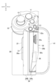
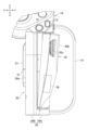
- 4 is a front view showing a grip of the input device; FIG. In this figure, the grip movable portion is arranged in the retracted position. 4 is a front view showing a grip of the input device; FIG. In this figure, the grip movable portion is arranged in an enlarged position.
- FIG. 4 is a side view showing an example of an input device;
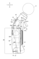
- FIG. 5 is a cross-sectional view taken along line VV in FIG. 4; In this figure, the grip movable portion is arranged in the retracted position.
- FIG. 5 is a cross-sectional view taken along line VV in FIG. 4; In this figure, the grip movable portion is arranged in an enlarged position.
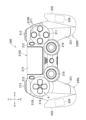
- FIG. 4 is a front view showing another example of an input device;
- FIG. 4 is a plan view showing another example of an input device;
- an input device 100 used for operating a game machine will be described as an example of an input device proposed in the present disclosure.
- the present disclosure also applies to input devices used to operate information processing devices different from game machines (for example, input devices used to operate simulation devices, input devices used to operate vehicles, ships, and aircraft). etc.) may be applied.
- directions indicated by X1 and X2 in FIG. 1 are referred to as right and left, respectively, and directions indicated by Y1 and Y2 are referred to as forward and rearward, respectively. Also, the directions indicated by Z1 and Z2 are referred to as upward and downward, respectively. These directions are used to describe the relative positional relationships of the elements (parts, members, portions) of the input device 100, and do not specify the orientation of the input device 100 during use.
- the input device 100 has one grip 30 for the user to hold.
- the grip 30 is rod-shaped and extends vertically.
- the input device 100 has a plurality of operation members that are operated by the user's fingers. A plurality of operating members are positioned above the grip 30 .
- the input device 100 has push buttons 11, 12, 13, and 14 as examples of a plurality of operation members.
- the input device 100 also has an operation stick 15 as an example of an operation member.
- the operation stick 15 can be tilted in its radial direction or rotated while being tilted.
- the operation stick 15 is positioned to the left of the push buttons 11 to 14 and protrudes left of the left side surface 30 a of the grip 30 .
- the input device 100 has a trigger button 16 (see FIG. 4).
- the input device 100 has an operation section 10 positioned above the grip 30 .
- the push buttons 11 , 12 , 13 , 14 and the operation stick 15 are provided on the front surface 10 a of the operation section 10 .
- the trigger button 16 is provided on the side opposite to the push buttons 11, 12, 13, 14 (that is, on the rear side of the operation section 10).
- the trigger button 16 can move around a center line Ax1 (see FIG. 4) extending in the horizontal direction.
- the user operates the operation member with fingers while gripping the grip 30 . Specifically, the user operates the push buttons 11, 12, 13, and 14 and the operation stick 15 with the thumb. Also, the user operates the trigger button 16 with the index finger.
- the input device 100 wirelessly or wiredly transmits signals corresponding to the operations of the buttons 11 to 16 to the game apparatus.
- the operation buttons 11 to 14, the operation stick 15, and the trigger button 16 are not distinguished, they are referred to as operation members 11 to 16.
- the front surface 10a of the operation portion 10 on which the operation members 11 to 15 are provided is inclined forward with respect to the extending direction (vertical direction) of the grip 30 (see FIG. 4). Unlike the input device 100 , the front surface 10 a of the operation section 10 may be parallel to the extending direction of the grip 30 .
- the input device 100 may have a cross key instead of the operation stick 15 or together with the operation stick 15 .
- the input device 100 may also have a linear push button at the location of the trigger button 16 .
- the input device 100 may have only one operating member.
- the position where the operating member is arranged is not limited to the operating portion 10 positioned above the grip 30 .
- the operating member may be arranged on the grip 30 .
- a push button 37 may be arranged on the grip 30 as shown in FIG.
- the input device 100 may have a light emitting section 2 (see FIG. 1).
- the light emitting unit 2 is, for example, ball-shaped and is arranged at the top of the input device 100 .
- the game machine tracks the position and size of the light emitting unit 2 through a camera connected to the game machine, and executes information processing related to the game based on the obtained information.
- the number, position, shape, etc. of the light emitting units 2 are not limited to the example described here.
- one or more light emitting units may be arranged in a state of being embedded inside the housing of the input device.
- the input device 100 may not have the light emitting unit 2 .
- the “side surface” of the grip 30 is a surface surrounding the center line Lc (see FIG. 2) of the grip 30 along the vertical direction.
- the grip 30 is, for example, a substantially quadrangular prism, and has a right side 30b, a left side 30a, a front side 30c, and a rear side as side surfaces.
- the grip 30 may be cylindrical.
- the input device 100 is a right-handed device, and the user's palm touches the right side 30b of the grip 30 (see FIG. 2).
- the input device 100 is configured such that the relative position between the operation section 10 and the side surface of the grip 30 can be changed in the left-right direction.
- the input device 100 is configured such that the relative positions of the operation members 11 to 16 provided in the operation section 10 and the side surfaces of the grip 30 can be changed in the horizontal direction. Since the input device 100 is for the right hand as described above, the relative positions of the operation members 11 to 16 provided on the operation section 10 and at least the right side surface 30b of the grip 30 can be changed in the horizontal direction.
- the grip movable portion 32 has a first position (the position of the grip movable portion 32 shown in FIG. 3A) close to the grip body 31, and a second position (the position of the grip movable portion 32 shown in FIG. 3B) away from the grip body 31 in the left-right direction. position of the grip movable part 32 shown).
- the first position will be referred to as the "reduced position” and the second position will be referred to as the "enlarged position.”
- the distance between the movable grip part 32 and the grip main body 31 in the expanded position is greater than the distance between the movable grip part 32 and the grip main body 31 in the contracted position.
- the grip body 31 is provided with a push button 37 (see FIG. 5A).
- the push button 37 is located on the side opposite to the grip body 31 in the left-right direction (see FIG. 5A).
- the movement direction of the grip movable portion 32 does not have to be the left-right direction.
- the grip movable part 32 may move obliquely forward and rightward from the grip body 31 , obliquely move rearward and rightward from the grip body 31 , or move obliquely downward and rightward from the grip body 31 .
- the grip movable portion 32 may move in a direction intersecting the extending direction (vertical direction) of the grip 30 so that the distance between the right side surface 30b of the grip 30 and the operation members 11 to 16 changes.
- a position adjustment mechanism 35 (see FIGS. 5A and 5B) is arranged between the grip movable part 32 and the grip body 31 for adjusting their relative positions.
- the position adjustment mechanism 35 has a position adjustment operation section 35c (see FIG. 2) operated by the user. The user can set the position of the grip movable part 32 to a reduced position, an enlarged position, and any position therebetween by operating the position adjustment operation part 35c.
- the position adjustment mechanism 35 will be detailed later.
- the position of the grip movable part 32 is not limited to the example described here.
- input device 100 may be a left-handed device.
- the grip movable portion 32 may be positioned on the left side of the grip main body 31 and constitute the left side surface 30 a (see FIG. 1) of the grip 30 .
- the grip 30 may be cylindrical in shape.
- the grip movable portion 32 may constitute the right portion (right side) of the outer peripheral surface of the cylinder.
- the grip movable portion 32 is positioned at least above the grip 30 . According to this arrangement of the grip movable part 32, by adjusting the relative positions of the grip movable part 32 and the operation part 10, a distance suitable for the length of the finger is secured between the grip movable part 32 and the operation members 11 to 16. easier to be In one example, the grip movable portion 32 is positioned at the top of the grip 30, and the upper edge 32a of the grip movable portion 32 is positioned along the lower edge 10b of the operation portion 10, as shown in FIG. 3A. Further, the upper edge 32a of the grip movable portion 32 is higher than the position of the upper edge 37a (see FIG. 4) of the operation button 37 provided on the grip 30. As shown in FIG.
- the grip movable part 32 extends downward from the upper edge 32a. As shown in FIG. 4, the length of the grip movable portion 32 in the vertical direction is greater than half the length of the grip 30 in the vertical direction. More specifically, the length of the grip movable portion 32 in the vertical direction is greater than two thirds of the length of the grip 30 in the vertical direction.
- the position and size of the grip movable part 32 are not limited to the examples described here.
- the size (length) of the grip movable portion 32 may be approximately half the length of the grip 30 in the vertical direction, or may be smaller than half.
- the grip movable portion 32 is curved so as to surround the center line Lc of the grip 30 along the vertical direction. That is, the grip movable portion 32 is curved to have an arcuate horizontal cross section.
- the grip movable portion 32 forms a right side surface 30b and a front side surface 30c of the grip 30. As shown in FIG.
- the grip movable part 32 forms a space for arranging parts inside thereof. In one example, an adjustment mechanism 35 and a vibration motor 36, which will be described later, are arranged inside the grip movable portion 32 (see FIG. 5A).
- the grip movable portion 32 has a supported portion 32b rotatably supported at its lower end.
- the supported portion 32b is rotatable around a center line extending in the front-rear direction.
- the shaft 33 supported by the lower end of the grip body 31 is inserted into a hole formed in the supported portion 32b, and the supported portion 32b is supported by the shaft 33 and rotates around the shaft 33. It is possible. Therefore, the grip movable portion 32 can move in the horizontal direction around the shaft 33 .
- the supporting structure of the grip movable part 32 can be simplified compared to the structure in which the grip movable part 32 moves in parallel.
- the position of the upper portion of the movable grip portion 32 changes more in the lateral direction than the lower portion, so that the necessary movable range of the movable grip portion 32 can be easily secured.
- the size (length) of grip movable portion 32 is greater than half the length of grip 30 . This also contributes to the expansion of the movable range of the upper portion of the grip movable portion 32 .
- the support structure of the grip movable portion 32 is not limited to the example described here.
- grip 30 may not have axis 33 .
- one of the lower end of the grip main body 31 and the lower end of the movable grip portion 32 is formed with a convex portion projecting in the front-rear direction, and the other of the lower end of the grip main body 31 and the lower end of the movable grip portion 32 is formed with A recess may be formed to hold the protrusion so that the protrusion is rotatable. By doing so, the grip movable portion 32 can move around the convex portion.
- the grip movable part 32 may be supported so as to be able to move in parallel. That is, the grip movable portion 32 may be supported by the grip body 31 so that both the upper end and the lower end of the grip movable portion 32 move in the horizontal direction.
- a supported portion 32 b that is rotatably supported may be provided at the upper end of the grip movable portion 32 . In this case, the supported portion 32 b may be supported by the operating portion 10 instead of the grip body 31 .
- the input device 100 has hand holding members for fixing the user's hands to the sides of the grip 30 .
- the hand holding member allows the user to release the grip 30 when using the input device 100 . That is, the user can extend the hand holding the grip 30 .
- the input device 100 has a band 41 arranged along the grip 30 and extending vertically as a hand holding member.
- the band 41 forms a gap between the grip 30 and the user's hand.
- the band 41 is positioned on the right side of the grip 30 and arranged along the grip movable portion 32 . Therefore, the user can put his hand between the band 41 and the grip movable part 32 .
- FIG. 4 when the input device 100 is viewed from the side (that is, when the input device 100 is viewed in the direction in which the grip movable section 32 moves), the band 41 overlaps the grip movable section 32 .
- the end of the band 41 is attached to the input device 100 at a position beyond the end of the grip movable part 32.
- the relative position between the movable grip portion 32 and the band 41 (the distance between the movable grip portion 32 and the band 41) can be changed.
- the upper end 41a of the band 41 is attached to the operation section 10 at a position higher than the upper edge 32a of the grip movable section 32, as shown in FIG. 5A.
- the lower end 41b of the band 41 is attached to the grip body 31 at a position lower than the lower end of the grip movable portion 32 .
- the upper end 41 a of the band 41 may be attached to the grip body 31 .
- the lower end 41 b of the band 41 may be attached to the lower end of the grip movable portion 32 .
- the band 41 is configured such that its length is adjustable. By reducing the length of the band 41 , the gap between the band 41 and the movable grip portion 32 becomes smaller, and the user's hand is pressed against the movable grip portion 32 .
- the structure for fixing the user's hand to the side surface of the grip 30 is not limited to the example described here.
- the upper end 41a and the lower end 41b of the band 41 may be attached to the upper end and the lower end of the grip movable portion 32, respectively.
- the input device 100 may have a glove into which the user's hand can be fitted, instead of the band 41, as a hand holding member for fixing the user's hand to the side surface of the grip 30. good.
- the grip body 31 has a housing 34 as shown in FIG. 5A.
- the housing 34 has two housing parts 34A, 34B which are mated together.
- the two housing parts 34A, 34B are combined in the left-right direction, for example.
- the housing 34 may be composed of two housing parts that are assembled in the front-rear direction.
- the grip body 31 is provided with a push button 37 .
- the push button 37 protrudes outward from an opening formed in the housing 34 .
- a frame 38 and a switch 38a attached to the frame 38 for detecting movement of the push button 37 are arranged inside the housing 34 .
- Various electrical components such as a circuit board and a battery may be arranged inside the housing 34 together with the frame 38 .
- the input device 100 has a position adjustment mechanism 35 (see FIG. 5A) for adjusting the relative positions of the operation members 11 to 16 and the side surface of the grip 30. As shown in FIG. The position adjustment mechanism 35 is arranged between the grip movable portion 32 and the grip body 31 . The position adjustment mechanism 35 also has a position adjustment operation section 35c (see FIG. 2) operated by the user. By operating the position adjustment operation section 35c, the user can set the position of the grip movable section 32 to a reduced position, an enlarged position, and any position therebetween.
- the input device 100 converts the rotational force applied to the position adjustment operation portion 35c into the movement of the movable member 35A in the rectilinear direction.
- the position adjusting mechanism 35 has a threaded portion 35a and a nut portion 35b inside which the threaded portion 35a is fitted.
- One of the threaded portion 35a and the nut portion 35b is provided on the grip main body 31 side, and the other of the threaded portion 35a and the nut portion 35b is provided on the grip movable portion 32 side.
- One of the screw portion 35a and the nut portion 35b is formed integrally with the position adjustment operation portion 35c.
- the position adjustment mechanism 35 has a movable member 35A.
- a position adjustment operating portion 35c and a screw portion 35a are formed on the movable member 35A.
- the nut portion 35b is formed in the housing 34 of the grip body 31.
- the nut portion 35b is formed integrally with one housing portion 34A of the housing 34 by resin. This makes it possible to reduce the number of parts and the number of manufacturing processes.
- the position adjusting mechanism 35 is arranged so that the center line Ls (see FIG. 5A) of the screw portion 35a and the nut portion 35b faces the movement direction (horizontal direction) of the grip movable portion 32.
- FIG. 5B by rotating the movable member 35A (position adjustment operation portion 35c) in one direction, the movable member 35A moves away from the grip body 31, and the distance between the grip body 31 and the grip movable portion 32 increases. Expanding. Further, by rotating the movable member 35A (position adjustment operation portion 35c) in the opposite direction, the movable member 35A moves in a direction approaching the grip main body 31, and the distance between the grip main body 31 and the grip movable portion 32 is reduced (Fig. 5A reference).
- the position adjustment mechanism 35 is attached to the grip body 31 and not attached to the grip movable portion 32 . That is, the movable member 35A is not attached to the inner surface of the grip movable portion 32. As shown in FIG. Therefore, the movable member 35A is rotatable relative to the grip movable portion 32. As shown in FIG.
- the grip movable portion 32 may be biased toward the grip main body 31 by an elastic member (for example, a spring).
- a torsion spring that biases the grip main body 31 side may be attached to the shaft 33 that supports the grip movable portion 32 .
- the position adjustment operation portion 35c is disk-shaped and expands in the radial direction of the screw portion 35a.
- the grip movable portion 32 is curved so as to cover the front side and the rear side of the position adjustment mechanism 35 . As shown in FIG. 2, the outer peripheral portion of the position adjustment operation portion 35c is partially exposed from the side surface of the grip 30. As shown in FIG. In the input device 100, the grip movable portion 32 is formed with an opening 32c that exposes the outer peripheral portion of the position adjustment operation portion 35c. The opening 32c is formed on the front side of the grip movable portion 32. As shown in FIG.
- the grip body 31 is formed with stopper portions 31 a and 39 b that define the movable range of the grip movable portion 32 .
- the grip movable portion 32 is formed with a stopper-receiving portion 32f that contacts the stopper portions 31a and 39b.
- the stopper portion 31a contacts the stopper-receiving portion 32f and restricts the grip movable portion 32 from moving beyond the enlarged position.
- the stopper portion 39b contacts the stopper-receiving portion 32f and restricts the grip movable portion 32 from moving beyond the retracted position.
- the stopped portion 32f protrudes upward from the upper edge 32a of the grip movable portion 32.
- the right housing 34A of the grip body 31 is formed with an opening into which the stopped portion 32f is fitted. The edge on the right side of this opening functions as a stopper portion 31a (see FIG. 5B).
- a frame 39 is arranged inside the housing 34 . The right side surface of the frame 39 functions as a stopper portion 39b (see FIG. 5A).
- the structure of the position adjustment mechanism 35 is not limited to the example described here.
- the nut portion 35b may be formed separately from the housing portion 34A and attached to the housing portion 34A.
- the threaded portion 35a may be attached to the housing portion 34A and the nut portion 35b may be arranged on the grip movable portion 32 side.
- the nut portion 35b and the position adjustment operating portion 35c may be formed on the movable member 35A.
- the position adjustment mechanism 35 may be attached to the grip movable portion 32 instead of the grip body 31 .
- one of the two parts (the nut portion 35b and the threaded portion 35a) constituting the position adjustment mechanism 35 is rotatably connected to the inner surface of the grip movable portion 32, and the other is connected to the housing 34 of the grip body 31. may be attached to the
- the movable member 35A of the position adjustment mechanism 35 may be vertically slidable.
- An inclined surface for converting the movement of the movable member 35A into the movement of the movable grip part 32 may be formed on the inner surface of the movable grip part 32 or the housing part 34A of the grip body 31 .
- the input device 100 may have a member that expands and contracts with air as the position adjustment mechanism 35 .
- vibration motor 36 As shown in FIG. 5A, input device 100 has vibration motor 36 in grip 30 .
- the vibration motor 36 is driven by power supplied from a battery (not shown).
- a control device (not shown) incorporated in the input device 100 controls the vibration motor 36 according to signals transmitted from the game machine, and causes the vibration motor 36 to vibrate according to events and actions that occur within the game space.
- the vibration motor 36 is attached to the grip movable portion 32. Therefore, when the position of the grip movable portion 32 is moved in the horizontal direction, the position of the vibration motor 36 is also moved accordingly. Since the position of the grip movable part 32 can be adjusted, the grip movable part 32 can be easily touched by the user's hand, and as a result, the vibration of the vibration motor 36 can be easily transmitted to the user's hand.
- the input device 100 has a hand holding member for fixing the user's hand to the side surface of the grip 30.
- the input device 100 has a band 41 arranged along the grip 30 .
- the band 41 overlaps the vibration motor 36 when the input device 100 is viewed in the direction in which the grip movable portion 32 moves (horizontal direction). Therefore, it is possible to effectively prevent the hand placed between the band 41 and the grip 30 from leaving the position of the vibration motor 36 .
- the vibration of the vibration motor 36 is effectively transmitted to the hand.
- the vibration motor 36 is, for example, a voice coil motor. That is, the vibration motor 36 has a coil and a magnet that can move relative to each other, and by controlling the current flowing through the coil, the magnet and the coil are relatively reciprocated in one direction.
- the vibration direction of the vibration motor 36 (the direction of relative movement between the magnet and the coil) is the direction orthogonal to the movement of the grip movable part 32 (the front-back direction, the up-down direction, and the direction oblique to them).
- the vibration direction of the vibration motor 36 may be the direction along the movement of the grip movable portion 32 (that is, the horizontal direction).
- Vibration motor 36 may be an eccentric motor. That is, the vibration motor 36 may have a rotating shaft, and a weight having a center of gravity at a position off the center of rotation may be attached to the rotating shaft.
- the vibration motor 36 is arranged between the grip movable portion 32 and the grip body 31. As described above, the grip movable portion 32 is curved to have an arcuate horizontal cross section. The vibration motor 36 is attached to the inner surface of the grip movable portion 32 and is covered with the grip movable portion 32 . That is, the front side and rear side of the vibration motor 36 are covered with the grip movable portion 32 .
- the width W1 of the vibration motor 36 in the horizontal direction is smaller than the width W2 of the vibration motor 36 in the vertical direction. Further, the width W1 of the vibration motor 36 in the left-right direction is smaller than the width W3 of the vibration motor 36 in the front-rear direction (see FIG. 4).
- a thin motor is used as the vibration motor 36 . This facilitates accommodation of the vibration motor 36 in the grip movable portion 32 .
- the vibration motor 36 is arranged so as to face the right side of the housing 34 of the grip body 31 .
- the housing 34 has, at a position corresponding to the vibration motor 36, a recess 34b in which the vibration motor 36 is arranged.
- the position adjusting mechanism 35 is arranged between the grip movable portion 32 and the grip main body 31 .
- the vibration motor 36 and the position adjustment mechanism 35 are arranged in the extending direction of the grip 30, that is, in the vertical direction. As a result, the space between the grip movable portion 32 and the grip body 31 can be effectively used.
- the position adjustment mechanism 35 is positioned above the vibration motor 36. That is, the distance from the rotation center of the supported portion 32b of the grip movable portion 32 to the position adjustment mechanism 35 is greater than the distance from the rotation center to the vibration motor 36.
- the vibration motor 36 is arranged inside the grip movable portion 32 on the side closer to the user's palm, and the vibration can be transmitted to the palm more effectively.
- the input device 100 includes a grip 30 having a right side surface 30b with which the user's palm touches, and an operation member positioned above the grip 30 for the user to operate with fingers. 11-16.
- the relative positions of the operation members 11 to 16 and the right side surface 30b of the grip 30 can be changed in the horizontal direction. According to this structure, the user can set the distance between the operation members 11 to 16 and the right side surface 30b of the grip 30 according to the length of his or her fingers. Therefore, the user can comfortably operate the buttons.
- the grip 30 has the grip main body 31 and the grip movable portion 32, and the relative positions of the grip movable portion 32 and the grip main body 31 can be moved in the horizontal direction. Unlike the input device 100 , the grip 30 as a whole may move in the horizontal direction relative to the operation section 10 .
- FIG. 6 is a front view showing an example of an input device 300 having such a structure.
- Input device 300 has a grip 330 .
- the grip 330 moved to the right is indicated by a solid line
- the grip 330 in the initial position is indicated by a chain double-dashed line.
- the grip 330 as a whole is movable in the horizontal direction with respect to the operation unit 10 .
- the relative positions of the operating members 11 to 16 and the right side surface 30b of the grip 330 relatively change in the horizontal direction.
- the user can set the distance between the operation members 11 to 16 and the right side surface 30b of the grip 30 according to the length of his or her fingers.
- the input device 100 may be configured for the left hand.
- the grip movable portion 32 and the band 41 may be positioned to the left of the grip body 31 .
- the input device 100 has the grip 30 having the right side surface 30b with which the user's palm touches, and the operation members 11 to 16 that are operated by the user's fingers.
- the grip 30 includes a grip main body 31 , a grip movable portion 32 forming a right side surface 30 b of the grip 30 , and a vibration motor 36 attached to the grip movable portion 32 .
- the relative positions of the grip main body 31 and the grip movable portion 32 can be changed in the horizontal direction.
- the grip movable part 32 is easily touched by the user's hand, and as a result, the vibration of the vibration motor 36 is easily transmitted to the user's hand.
- the direction in which the grip movable portion 32 moves is not limited to the horizontal direction.
- the grip movable portion 32 may move relative to the grip body 31 in the front-back direction and the up-down direction.
- the structure proposed in the present disclosure is not limited to the structure of the input device 100.
- the input device 100 has one grip 30 .
- the structure proposed in this disclosure may be applied to an input device having two left and right separated grips.
- a push button 213 is also arranged on the front surface of the left operation unit 210L.
- a central operation unit 210C is provided between the left and right operation units 210R and 210L.
- a plate-shaped button 215 to which a touch sensor is attached is provided on the upper surface of the central operation unit 210C.
- Left and right operation sticks 216 are provided behind the plate-like button 215 .
- the grips 230R and 230L are provided with a grip main body 231 connected to the operating portions 210R and 210L, respectively, and a grip movable portion 232 located outside the grip main body 231 in the left-right direction.
- the relative positions of the grip movable portion 232 and the grip main body 231 can be changed in the horizontal direction.
- FIG. 7 shows a state in which the grip movable portion 232 is separated from the grip main body 231 outward in the left-right direction.
- the grip movable portion 232 may be translatable in the left-right direction, or may be movable in the left-right direction around an axis.
- the grips 230R and 230L have a vibration motor 236 attached to the inner surface of the grip movable portion 232. As shown in FIG. This allows the vibration of the vibration motor 236 to be effectively transmitted to the user's hand.
Landscapes
- Engineering & Computer Science (AREA)
- Multimedia (AREA)
- General Engineering & Computer Science (AREA)
- Human Computer Interaction (AREA)
- Theoretical Computer Science (AREA)
- Physics & Mathematics (AREA)
- General Physics & Mathematics (AREA)
- Position Input By Displaying (AREA)
- User Interface Of Digital Computer (AREA)
Priority Applications (5)
| Application Number | Priority Date | Filing Date | Title |
|---|---|---|---|
| EP21958349.9A EP4406629A4 (en) | 2021-09-21 | 2021-09-21 | ENTRY DEVICE WITH AN ADJUSTABLE HANDLE |
| JP2023549204A JP7594680B2 (ja) | 2021-09-21 | 2021-09-21 | 可変グリップを有する入力デバイス |
| US18/691,182 US20240382839A1 (en) | 2021-09-21 | 2021-09-21 | Input device |
| CN202180101072.3A CN117716328A (zh) | 2021-09-21 | 2021-09-21 | 具有可变手柄的输入设备 |
| PCT/JP2021/034652 WO2023047472A1 (ja) | 2021-09-21 | 2021-09-21 | 可変グリップを有する入力デバイス |
Applications Claiming Priority (1)
| Application Number | Priority Date | Filing Date | Title |
|---|---|---|---|
| PCT/JP2021/034652 WO2023047472A1 (ja) | 2021-09-21 | 2021-09-21 | 可変グリップを有する入力デバイス |
Publications (1)
| Publication Number | Publication Date |
|---|---|
| WO2023047472A1 true WO2023047472A1 (ja) | 2023-03-30 |
Family
ID=85720277
Family Applications (1)
| Application Number | Title | Priority Date | Filing Date |
|---|---|---|---|
| PCT/JP2021/034652 Ceased WO2023047472A1 (ja) | 2021-09-21 | 2021-09-21 | 可変グリップを有する入力デバイス |
Country Status (5)
| Country | Link |
|---|---|
| US (1) | US20240382839A1 (cg-RX-API-DMAC7.html) |
| EP (1) | EP4406629A4 (cg-RX-API-DMAC7.html) |
| JP (1) | JP7594680B2 (cg-RX-API-DMAC7.html) |
| CN (1) | CN117716328A (cg-RX-API-DMAC7.html) |
| WO (1) | WO2023047472A1 (cg-RX-API-DMAC7.html) |
Families Citing this family (1)
| Publication number | Priority date | Publication date | Assignee | Title |
|---|---|---|---|---|
| WO2023047473A1 (ja) | 2021-09-21 | 2023-03-30 | 株式会社ソニー・インタラクティブエンタテインメント | 入力デバイス |
Citations (5)
| Publication number | Priority date | Publication date | Assignee | Title |
|---|---|---|---|---|
| US6394906B1 (en) | 1997-09-22 | 2002-05-28 | Sony Computer Entertainment Inc. | Actuating device for game machine |
| JP2003199974A (ja) * | 2000-09-28 | 2003-07-15 | Immersion Corp | 触覚フィードバックインターフェースデバイス用の方向接触フィードバック |
| JP2012055340A (ja) * | 2010-09-03 | 2012-03-22 | Hori Co Ltd | ゲーム機用コントローラ |
| JP2017000757A (ja) * | 2015-06-12 | 2017-01-05 | 任天堂株式会社 | ゲームコントローラ |
| WO2017221432A1 (ja) * | 2016-06-21 | 2017-12-28 | 株式会社ホリ | ゲーム機用コントローラ |
Family Cites Families (6)
| Publication number | Priority date | Publication date | Assignee | Title |
|---|---|---|---|---|
| JP4805633B2 (ja) * | 2005-08-22 | 2011-11-02 | 任天堂株式会社 | ゲーム用操作装置 |
| CN101663074B (zh) * | 2006-11-10 | 2012-03-28 | 雷泽亚太有限公司 | 可以人机工程学的方式配置的游戏控制器 |
| WO2017149888A1 (ja) * | 2016-03-04 | 2017-09-08 | 株式会社ソニー・インタラクティブエンタテインメント | 操作装置 |
| US20180369691A1 (en) * | 2017-06-22 | 2018-12-27 | Immersion Corporation | Device having a plurality of segments for outputting a rotational haptic effect |
| US11229837B2 (en) * | 2017-08-31 | 2022-01-25 | Sony Corporation | Haptic presentation apparatus |
| WO2019113245A1 (en) * | 2017-12-07 | 2019-06-13 | Valve Corporation | Electronic controller with a hand retainer, outer shell, and finger sensing |
-
2021
- 2021-09-21 JP JP2023549204A patent/JP7594680B2/ja active Active
- 2021-09-21 CN CN202180101072.3A patent/CN117716328A/zh active Pending
- 2021-09-21 WO PCT/JP2021/034652 patent/WO2023047472A1/ja not_active Ceased
- 2021-09-21 EP EP21958349.9A patent/EP4406629A4/en active Pending
- 2021-09-21 US US18/691,182 patent/US20240382839A1/en active Pending
Patent Citations (5)
| Publication number | Priority date | Publication date | Assignee | Title |
|---|---|---|---|---|
| US6394906B1 (en) | 1997-09-22 | 2002-05-28 | Sony Computer Entertainment Inc. | Actuating device for game machine |
| JP2003199974A (ja) * | 2000-09-28 | 2003-07-15 | Immersion Corp | 触覚フィードバックインターフェースデバイス用の方向接触フィードバック |
| JP2012055340A (ja) * | 2010-09-03 | 2012-03-22 | Hori Co Ltd | ゲーム機用コントローラ |
| JP2017000757A (ja) * | 2015-06-12 | 2017-01-05 | 任天堂株式会社 | ゲームコントローラ |
| WO2017221432A1 (ja) * | 2016-06-21 | 2017-12-28 | 株式会社ホリ | ゲーム機用コントローラ |
Non-Patent Citations (1)
| Title |
|---|
| See also references of EP4406629A4 |
Also Published As
| Publication number | Publication date |
|---|---|
| CN117716328A (zh) | 2024-03-15 |
| EP4406629A4 (en) | 2025-07-09 |
| JPWO2023047472A1 (cg-RX-API-DMAC7.html) | 2023-03-30 |
| JP7594680B2 (ja) | 2024-12-04 |
| US20240382839A1 (en) | 2024-11-21 |
| EP4406629A1 (en) | 2024-07-31 |
Similar Documents
| Publication | Publication Date | Title |
|---|---|---|
| JP7271588B2 (ja) | 操作入力装置 | |
| US20240033617A1 (en) | Controller for video game console | |
| JP6745307B2 (ja) | 操作装置 | |
| CN106861180B (zh) | 游戏控制器 | |
| CN105188864B (zh) | 游戏控制器 | |
| EP3638384B1 (en) | Input apparatus for a games console | |
| US6624806B2 (en) | Joystick capable of controlling direction rudder and accelerator synchronously | |
| JP2014061225A (ja) | ゲーム機用のコントローラ | |
| JP7653497B2 (ja) | 入力デバイス | |
| CN1965288A (zh) | 用户接口设备 | |
| WO2023047472A1 (ja) | 可変グリップを有する入力デバイス | |
| JP2017217414A (ja) | ゲームコントローラ | |
| US20210394799A1 (en) | Integrated control apparatus for autonomous vehicle | |
| WO2023047471A1 (ja) | 可変グリップを有する入力デバイス | |
| JP3108313U (ja) | ゲーム機用コントローラ | |
| JP7399132B2 (ja) | ラジオコントロール送信機 | |
| JP2018129193A (ja) | スイッチ装置 | |
| JP6436857B2 (ja) | 操作装置 | |
| KR102546960B1 (ko) | 4방향 시소 및 푸시 기능을 구비한 순간형 스위치 | |
| TW202434348A (zh) | 檢測裝置以及操作裝置 | |
| JP2006294416A (ja) | 多方向入力スイッチ | |
| JP2022169841A (ja) | 入力装置 | |
| JP2005149235A (ja) | 複数状態キースイッチを備えた電子機器および電子機器制御装置。 | |
| US20070290987A1 (en) | Multifunctional mouse | |
| HK1018019A (en) | Operating device for game machines |
Legal Events
| Date | Code | Title | Description |
|---|---|---|---|
| 121 | Ep: the epo has been informed by wipo that ep was designated in this application |
Ref document number: 21958349 Country of ref document: EP Kind code of ref document: A1 |
|
| WWE | Wipo information: entry into national phase |
Ref document number: 202180101072.3 Country of ref document: CN |
|
| WWE | Wipo information: entry into national phase |
Ref document number: 18691182 Country of ref document: US |
|
| WWE | Wipo information: entry into national phase |
Ref document number: 2023549204 Country of ref document: JP |
|
| WWE | Wipo information: entry into national phase |
Ref document number: 2021958349 Country of ref document: EP |
|
| NENP | Non-entry into the national phase |
Ref country code: DE |
|
| ENP | Entry into the national phase |
Ref document number: 2021958349 Country of ref document: EP Effective date: 20240422 |