WO2023047434A1 - 車室内照明制御装置、及び車室内照明制御方法 - Google Patents
車室内照明制御装置、及び車室内照明制御方法 Download PDFInfo
- Publication number
- WO2023047434A1 WO2023047434A1 PCT/JP2021/034447 JP2021034447W WO2023047434A1 WO 2023047434 A1 WO2023047434 A1 WO 2023047434A1 JP 2021034447 W JP2021034447 W JP 2021034447W WO 2023047434 A1 WO2023047434 A1 WO 2023047434A1
- Authority
- WO
- WIPO (PCT)
- Prior art keywords
- vehicle
- driver
- checking
- control device
- detected
- Prior art date
- Legal status (The legal status is an assumption and is not a legal conclusion. Google has not performed a legal analysis and makes no representation as to the accuracy of the status listed.)
- Ceased
Links
Images


Classifications
-
- B—PERFORMING OPERATIONS; TRANSPORTING
- B60—VEHICLES IN GENERAL
- B60Q—ARRANGEMENT OF SIGNALLING OR LIGHTING DEVICES, THE MOUNTING OR SUPPORTING THEREOF OR CIRCUITS THEREFOR, FOR VEHICLES IN GENERAL
- B60Q3/00—Arrangement of lighting devices for vehicle interiors; Lighting devices specially adapted for vehicle interiors
- B60Q3/80—Circuits; Control arrangements
-
- Y—GENERAL TAGGING OF NEW TECHNOLOGICAL DEVELOPMENTS; GENERAL TAGGING OF CROSS-SECTIONAL TECHNOLOGIES SPANNING OVER SEVERAL SECTIONS OF THE IPC; TECHNICAL SUBJECTS COVERED BY FORMER USPC CROSS-REFERENCE ART COLLECTIONS [XRACs] AND DIGESTS
- Y02—TECHNOLOGIES OR APPLICATIONS FOR MITIGATION OR ADAPTATION AGAINST CLIMATE CHANGE
- Y02B—CLIMATE CHANGE MITIGATION TECHNOLOGIES RELATED TO BUILDINGS, e.g. HOUSING, HOUSE APPLIANCES OR RELATED END-USER APPLICATIONS
- Y02B20/00—Energy efficient lighting technologies, e.g. halogen lamps or gas discharge lamps
- Y02B20/40—Control techniques providing energy savings, e.g. smart controller or presence detection
Definitions
- the present disclosure relates to a vehicle interior lighting control device and a vehicle interior lighting control method.
- Patent Document 1 is an example of a vehicle interior lighting control device, is to improve the visibility in the direction in which the passenger intends to see.
- the vehicle interior lighting device turns on the interior light when determining that the passenger is looking at the vehicle interior from at least one of the passenger's line of sight and face direction. Control the direction of the room light so as to illuminate at least one of the direction of the person's eyes and face.
- the vehicle interior lighting control device described above may turn on the interior light even when the driver tries to check the rear outside the vehicle. As a result, the interior lights become brighter, and there is a problem that the rearward visibility outside the vehicle cabin deteriorates.
- An object of the present disclosure is to provide a vehicle interior lighting control device that does not deteriorate the visibility of the driver behind the vehicle outside the vehicle.
- a vehicle interior lighting control device detects whether or not at least one of a driver and a passenger in a vehicle is checking the rear. 1 detector, a second detector for detecting whether or not the driver is checking the rear outside the vehicle, and the first detector detects at least one of the driver and the front passenger seat occupant.
- the interior light is turned on, and when the second detection unit detects that the driver is checking the rear outside the vehicle, the driving and a control unit that reduces the brightness of the interior light or prohibits lighting of the interior light compared to when it is detected that the person is not checking the rear outside the vehicle.
- the vehicle interior lighting control device According to the vehicle interior lighting control device according to the present disclosure, it is possible to prevent deterioration of the driver's visibility behind the vehicle.
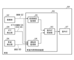
- FIG. 1 shows a configuration of a vehicle interior lighting control device SS according to an embodiment
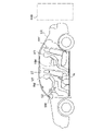
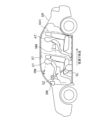
- 1 is a schematic diagram showing a vehicle SR, a driver UT, and a rear seat passenger KT according to the embodiment
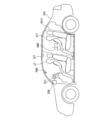
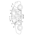
- FIG. It is a schematic diagram showing the vehicle SR of the embodiment, the front passenger JT, and the back seat crew KT.
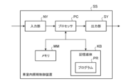
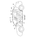
- 4 shows hardware of the vehicle interior lighting control device SS of the embodiment. It is a flow chart which shows operation of vehicle interior lighting control device SS of an embodiment. 4 shows actions of a driver UT according to the embodiment; 4 shows the operation of the passenger JT in the embodiment.
- FIG. 4 shows operation of a shift lever SL by a driver UT according to the embodiment; FIG.
- FIG. 1 shows the movement of the vehicle SR and the action of the driver UT according to the embodiment (part 1); Movement of the vehicle SR and operation of the driver UT in the embodiment are shown (part 2). Movement of the vehicle SR and operation of the driver UT in the embodiment are shown (Part 3).
- 7 is a flow chart showing the operation of the vehicle interior lighting control device SS of Modification 1.
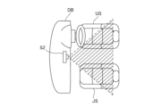
- FIG. 10 is a flowchart (Part 1) showing the operation of the vehicle interior lighting control device SS of Modified Example 2; 9 is a flowchart (Part 2) showing the operation of the vehicle interior lighting control device SS of Modification 2; The position where the imaging unit SZ of Modification 3 is arranged is shown.
- FIG. 11 shows an image GZ captured by an imaging unit SZ of Modified Example 3.
- FIG. 1 shows the configuration of a vehicle interior lighting control device SS according to an embodiment.
- FIG. 2 is a schematic diagram showing the vehicle SR, the driver UT, and the rear seat passenger KT of the embodiment.
- FIG. 3 is a schematic diagram showing the vehicle SR, front passenger JT, and back seat passenger KT of the embodiment.
- a vehicle SR (shown in FIGS. 1 to 3), which is a private car or the like, has, for example, three crew members. Specifically, in the vehicle SR, as shown in FIG. 2, a driver UT is seated in the driver's seat, and as shown in FIG. , is seated, and as shown in FIGS. 2 and 3, a rear seat occupant KT carrying a load NM is seated in the rear seat.
- the driver UT corresponds to the "driver”
- the passenger JT corresponds to the "passenger”.
- a vehicle interior lighting control device SS of the embodiment is mounted in a vehicle SR as shown in FIG.
- the vehicle SR is equipped with an imaging unit SZ, a gear detection unit GK, a vehicle speed detection unit SK, and an interior light ST in addition to the vehicle interior lighting control device SS.
- the imaging unit SZ (also shown in FIGS. 2 and 3) captures an image GZ of the interior of the vehicle SR.
- the imaging unit SZ images, for example, a driver UT, a front passenger seat passenger JT, a rear seat passenger KT, luggage NM, and the like in the vehicle SR.
- the imaging unit SZ is composed of, for example, a camera.
- the imaging unit SZ is arranged, for example, on the dashboard.
- the gear detection unit GK detects the gear type GS. More specifically, the gear detector GK detects which of drive gear, reverse gear, neutral, etc. is selected by operating a shift lever SL (for example, shown in FIG. 2) in the vehicle SR. The gear detection unit GK detects, for example, that the reverse gear is selected to reverse the vehicle SR.
- the vehicle speed detection unit SK detects the speed SD at which the vehicle SR moves.
- the vehicle speed detector SK detects, for example, that the vehicle SR is moving backward at a low speed (for example, 10 km/h or less).
- the vehicle SR includes, for example, an interior light ST (also shown in FIG. 1), rearview mirrors (rearview mirror RM and side mirror SM), and A shift lever SL is provided.
- the vehicle interior lighting control device SS includes a front seat occupant monitoring unit ZK, a driver monitoring unit UK, and an interior light control unit SC.
- the front seat occupant monitoring unit ZK corresponds to the "first detection unit”
- the driver monitoring unit UK corresponds to the "second detection unit”
- the interior light control unit SC corresponds to the "control unit”. do.
- the front seat occupant monitoring unit ZK sits on the front seat of the vehicle SR based on the line of sight, face direction, and body posture of the driver UT and the front passenger JT in the image GZ captured by the imaging unit SZ. At least one of the driver UT and the front passenger JT, who are sitting in the rear seat KH1 (shown in FIG. 2) in the vehicle SR, for example, the rear seat A seat occupant KT (shown in FIG. 3), or baggage NM held by a rear seat occupant KT (shown in FIGS. 2 and 3), or baggage placed on a rear seat (not shown). ) is monitored, that is, detected.
- the driver monitoring unit UK detects whether or not the driver UT is checking the rear KH2 (for example, shown in FIG. 2) outside the vehicle SR based on the gear type GS detected by the gear detection unit GK. do. For example, when the driver's face or posture faces backward and the gear detection unit GK detects that the reverse gear is selected, the driver monitoring unit UK detects that the driver UT is moving backward outside the vehicle SR. Detects confirmation of KH2.
- the driver monitoring unit UK also detects a direction HK in which the vehicle SR moves and a speed SD in which the vehicle SR moves, which are determined by information indicating the gear type GS (selection of the shift lever) detected by the gear detection unit GK. , it is detected whether or not the driver UT is checking the rear KH2 outside the vehicle SR. For example, when the vehicle speed detection unit SK detects that the vehicle SR is moving backward at a low speed, the driver monitoring unit UK will confirm that the driver UT is checking the rear KH2 outside the vehicle SR. to detect
- the driver monitoring unit UK may use the image GZ of the driver UT captured by the imaging unit SZ.
- the interior light control unit SC turns on the interior light ST based on the result of detection by the front seat occupant monitoring unit ZK and the result of detection by the driver monitoring unit UK.
- the interior light control unit SC turns on the interior light ST, and the driver UT confirms the rear KH2 outside the vehicle SR, the interior lamp ST is turned off.
- FIG. 4 shows the hardware of the vehicle interior lighting control device SS of the embodiment.
- the vehicle interior lighting control device SS of the embodiment includes a processor PC, a memory MM, and a storage medium KB as shown in FIG. 4 in order to perform the functions described above.
- the vehicle interior lighting control device SS of the embodiment further includes an input section NY and an output section SY as necessary.
- a processor PC is the core of a well-known computer that operates hardware according to software.
- the memory MM is composed of, for example, a DRAM (Dynamic Random Access Memory) and an SRAM (Static Random Access Memory).
- the storage medium KB is composed of, for example, a hard disk drive (HDD: Hard Disk Drive), a solid state drive (SSD: Solid State Drive), and a ROM (Read Only Memory).
- a storage medium KB stores a program PR.
- the program PR is a group of instructions that define the content of processing to be executed by the processor PC.
- the input unit NY is composed of, for example, a camera (imaging unit SZ), and also includes information (direction HK) indicating the type of gear GS detected by the gear detection unit GK, and vehicle speed (speed SD) detected by the vehicle speed detection unit SK. receive input of information indicating The output unit SY outputs, for example, information (not shown) for controlling the operation of the room light ST.
- the processor PC executes the program PR stored in the storage medium KB on the memory MM, and if necessary, By controlling the operations of the input section NY and the output section SY, the functions of the front seat occupant monitoring section ZK to the interior light control section SC are realized.
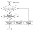
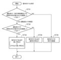
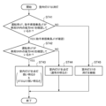
- FIG. 5 is a flow chart showing the operation of the vehicle interior lighting control device SS of the embodiment.
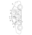
- FIG. 6 shows the actions of the driver UT of the embodiment.
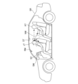
- FIG. 7 shows the motion of passenger JT in the embodiment.
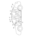
- FIG. 8 shows the operation of the shift lever SL by the driver UT of the embodiment.
- FIG. 9 shows the movement of the vehicle SR and the action of the driver UT in the embodiment (part 1).
- FIG. 10 shows the movement of the vehicle SR and the action of the driver UT in the embodiment (part 2).
- FIG. 11 shows the movement of the vehicle SR and the action of the driver UT in the embodiment (No. 3).
- FIG. 5 The operation of the vehicle interior lighting control device SS of the embodiment will be described with reference to FIGS. 5 to 11.
- FIG. 5 The operation of the vehicle interior lighting control device SS of the embodiment will be described with reference to FIGS. 5 to 11.
- FIG. 5 The operation of the vehicle interior lighting control device SS of the embodiment will be described with reference to FIGS. 5 to 11.
- FIG. 5 The operation of the vehicle interior lighting control device SS of the embodiment will be described with reference to FIGS. 5 to 11.
- the interior light ST (illustrated in FIGS. 1 to 3) is initially turned off.
- the driver UT confirms the rear KH1 (shown in FIG. 2) inside the vehicle SR. to be (3)
- the driver UT also checks the rear KH2 (shown in FIG. 2) outside the vehicle SR.
- Step ST11 The front seat occupant monitoring section ZK (shown in FIG. 1), based on the image GZ (shown in FIG. 1) taken by the imaging section SZ (shown in FIGS. 1 to 3), As shown in FIG. 7, it is determined, ie, detected, whether or not at least one of the driver UT and passenger JT is looking behind KH1 in the vehicle SR.
- the front-seat occupant monitoring unit ZK performs the above-mentioned detection by, as shown in FIGS. (illustrated by solid line arrows) and body posture (illustrated by other solid line arrows).
- step ST12 the process proceeds to step ST15.
- Step ST12 The driver monitoring unit UK determines, that is, detects whether or not the driver UT is checking the rear KH2 outside the vehicle SR.
- the driver monitoring unit UK performs said detection, for example, based on the following. (1) Whether or not the gear type GS selected by the shift lever SL (shown in FIG. 8) detected by the gear detector GK is a reverse gear (shown in FIG. 1). (2) Whether or not the gear type GS selected by the shift lever SL (shown in FIG. 8) is a reverse gear (shown in FIG. 1) detected by the gear detector GK, and whether the vehicle Whether or not the vehicle SR is moving backward at a low speed (shown in FIGS.
- step ST13 the process proceeds to step ST14.
- Step ST13 In step ST11, it is detected that the driver UT is checking the rear KH1 inside the vehicle SR, and in step ST12, it is detected that the driver UT is checking the rear KH2 outside the vehicle SR.
- the room light controller SC turns on the room light ST.
- step ST11 it is detected that the driver UT may be checking the rear KH1 inside the vehicle SR, and in step ST12, the driver UT is checking the rear KH2 outside the vehicle SR.
- the interior light controller SC dims the interior light ST.
- the interior light control unit SC turns on the interior light ST in step ST14 to indicate "normal brightness.”
- the room light ST is dimmed with "weak brightness” rather than "brightness".
- the notation of "brightness” described above and hereinafter is associated with luminance as follows. (1) “Strong brightness” corresponds to “high brightness illumination”. (2) “Normal Brightness” corresponds to “Medium Brightness Illumination”. (3) “weak brightness” corresponds to "low luminance illumination”;
- weak brightness includes being darker than “normal brightness” and substantially not lighting the room light ST, that is, substantially turning off the room light ST.
- Weak brightness is, for example, 60 to 80% brightness, assuming that "normal brightness” is 100% brightness.
- Step ST14 In step ST11, it is detected that the driver UT is checking the rear KH1 inside the vehicle SR, and in step ST12, it is detected that the driver UT is not checking the rear KH2 outside the vehicle SR.
- the room light controller SC turns on the room light ST with the above-described "normal brightness”.
- Step ST15 When it is detected in step ST11 that neither the driver UT nor the driver UT is checking the rear KH1 in the vehicle SR, the interior light controller SC continues to turn off the interior light ST. , that is, continue to turn off the light.
- the interior light control unit SC sets the interior light ST to "weaker brightness” than "normal brightness” in step ST14. light up. As a result, it is possible to prevent the driver UT from deteriorating the visibility, which is the ease with which the driver UT can check the rear KH2 outside the vehicle SR, that is, from hindering it.
- Modification 1 A vehicle interior lighting control device SS of Modification 1 will be described.
- the vehicle interior lighting control device SS of Modification 1 adjusts the color temperature of the interior light ST in addition to turning on the interior light ST in step ST13 of the vehicle interior lighting control device SS of the embodiment.
- FIG. 12 is a flow chart showing the operation of the vehicle interior lighting control device SS of Modification 1. As shown in FIG. 12
- Step ST21 The front seat occupant monitoring unit ZK (illustrated in FIG. 1) monitors one of the driver UT and front passenger JT as shown in FIGS. Detects whether at least one of them is checking the rear KH1 (shown in FIG. 2) in the vehicle SR.
- Step ST22 The driver monitoring unit UK (shown in FIG. 1), similarly to step ST12 of the embodiment, monitors the driver UT as shown in FIGS. 2.) is detected.
- Step ST23 The room light controller SC (illustrated in FIG. 1) turns on the room light ST with "weak brightness” rather than "normal brightness”, as in step ST13 of the embodiment.
- the room light control unit SC changes the color temperature of the room light ST in addition to or instead of turning on the room light ST. adjust. More specifically, the interior light control unit SC adjusts the color temperature of the interior light ST to, for example, From the viewpoint of color rendering properties, adjust to a reddish color.
- Step ST24 The room light controller SC turns on the room light ST with "normal brightness” in the same way as in step ST14 of the embodiment.
- Step ST25 The room light controller SC continues to turn off the room light ST in the same manner as in step ST15 of the embodiment.
- the interior light control unit SC sets the interior light ST to a level higher than "normal brightness” in the same manner as in step ST13 of the embodiment.
- the color temperature of the interior light ST is adjusted so as not to hinder the driver UT from checking the rear KH2 outside the vehicle SR. , for example, to adjust to a reddish color.
- the visibility of the driver UT at the rear KH2 outside the vehicle SR is not deteriorated, that is, it is possible to prevent obstruction, compared to the embodiment.
- Modification 2 A vehicle interior lighting control device SS of Modified Example 2 will be described.
- the vehicle interior lighting control device SS of Modification 2 turns on the interior light ST
- the brightness of the interior light ST when the driver UT is checking the rear KH1 in the vehicle SR is controlled by the front passenger JT.
- the brightness of the room light ST is made stronger than that of the room light ST when the driver is checking the rear KH1 in the vehicle SR.
- FIG. 13 is a flowchart (Part 1) showing the operation of the vehicle interior lighting control device SS of Modification 2. As shown in FIG.
- FIG. 14 is a flowchart (Part 2) showing the operation of the vehicle interior lighting control device SS of Modification 2.
- Part 2 a flowchart showing the operation of the vehicle interior lighting control device SS of Modification 2.
- the flowchart of FIG. 13 assumes the following.
- Step ST31 The front seat occupant monitoring section ZK (shown in FIG. 1) checks the rear seat KH1 in the vehicle SR as shown in FIG. detect whether or not there is
- Step ST41 As in step ST11 of the embodiment, the front seat occupant monitoring unit ZK monitors the passenger seat passenger JT in the vehicle SR instead of the driver UT in step ST31 as shown in FIG. It is detected whether or not the backward KH1 is confirmed.
- Steps ST32 and ST42 The driver monitoring unit UK (illustrated in FIG. 1), similarly to step ST12 of the embodiment, monitors the driver UT as shown in FIGS. Detects whether or not KH2 is confirmed.
- Step ST33 The room light controller SC (illustrated in FIG. 1) turns on the room light ST as in step ST13 of the embodiment. More precisely, similar to step ST13 of the embodiment, the interior light control unit SC sets the "lower brightness” than the above-described "normal brightness” and is different from step ST13 of the embodiment. The room light ST is turned on with "strong brightness” than "brightness at step ST43".
- Step ST43 The room light controller SC turns on the room light ST, as in step ST13 of the embodiment. More precisely, similar to step ST13 of the embodiment, the interior light control unit SC controls the brightness to be "weaker” than the above-described "normal brightness” and, unlike step ST13 of the embodiment, The room light ST is turned on with "weaker brightness” than "brightness at step ST33".
- Steps ST34, ST44 The room light control unit SC lights the room light ST with the above-described "normal brightness", as in step ST14 of the embodiment.
- Steps ST35 and ST45 The interior light controller SC continues to turn off the interior light ST, as in step ST15 of the embodiment.
- the interior light control unit SC determines that the interior light ST is turned on in step ST33, and the brightness that causes the interior light ST to turn on is determined in step ST43. This is done so that the brightness becomes stronger than the lighting of the lamp ST.
- the driver UT checks the rear KH1 in the vehicle SR in step ST33, and the front passenger JT checks the rear KH1 in the vehicle SR in step ST43. will be done in As a result, the driver UT can complete confirmation of the rear KH1 in a shorter time than confirmation of the rear KH1 by the front passenger JT.
- Modification 3 A vehicle interior lighting control device SS of Modified Example 3 will be described.
- the imaging unit SZ (illustrated in FIG. 1) has, as a camera, a wide-angle camera capable of imaging both the driver UT and the front passenger JT.
- FIG. 15 shows the position where the imaging unit SZ of Modification 3 is arranged.
- FIG. 16 shows an image GZ captured by the imaging unit SZ of Modification 3.
- the imaging unit SZ having a wide-angle camera is arranged, for example, on the dashboard DB of the vehicle SR, as in the embodiment, as shown in FIG.
- the board DB is arranged between the driver's seat US and the passenger's seat JS.
- the imaging unit SZ having a wide-angle camera can simultaneously image both the driver's seat US and the passenger's seat JS. Both can be imaged simultaneously.
- the imaging unit SZ having a wide-angle camera captures an image GZ (shown in FIG. 1) including the eyes, faces, and upper bodies of both the driver UT and the front passenger JT. It is possible.
- the front seat occupant monitoring unit ZK (shown in FIG. 1) monitors whether either the driver UT or the passenger JT is in the vehicle SR in step ST11 of the embodiment, as shown in FIGS. An image GZ ( 16.).
- the driver monitoring unit UK detects that the driver UT is behind KH2 outside the vehicle SR (shown in FIG. 2), as shown in FIGS. See also the image GZ (shown in FIG. 16) of both the driver UT and the front passenger JT taken by the imaging unit SZ having a wide-angle camera. do.
- the imaging section SZ is composed of a wide-angle camera.
- the front seat occupant monitoring unit ZK and the driver monitoring unit UK perform the above-described detections of the driver UT and the driver UT and This can be done based on the line of sight, face orientation, posture, etc., of the passenger JT.
- the vehicle interior lighting control device can be used to prevent deterioration of the driver's visibility behind the vehicle.
- DB Dashboard GK Gear detector, GS Gear type, GZ Image, HK Direction, JS Passenger seat, JT Passenger seat occupant, KB Storage medium, KH1 Rear inside vehicle, KH2 Rear outside vehicle, KT Rear seat boarding Personnel, MM memory, NM luggage, NY input unit, PC processor, PR program, RM room mirror, SC room light control unit, SD speed, SK vehicle speed detection unit, SL shift lever, SM side mirror, SR vehicle, SS vehicle interior Lighting control device, ST room light, SY output unit, SZ imaging unit, UK driver monitoring unit, US driver's seat, UT driver, ZK front seat occupant monitoring unit.
Landscapes
- Engineering & Computer Science (AREA)
- Mechanical Engineering (AREA)
- Arrangements Of Lighting Devices For Vehicle Interiors, Mounting And Supporting Thereof, Circuits Therefore (AREA)
Priority Applications (2)
| Application Number | Priority Date | Filing Date | Title |
|---|---|---|---|
| JP2023549170A JP7459392B2 (ja) | 2021-09-21 | 2021-09-21 | 車室内照明制御装置、及び車室内照明制御方法 |
| PCT/JP2021/034447 WO2023047434A1 (ja) | 2021-09-21 | 2021-09-21 | 車室内照明制御装置、及び車室内照明制御方法 |
Applications Claiming Priority (1)
| Application Number | Priority Date | Filing Date | Title |
|---|---|---|---|
| PCT/JP2021/034447 WO2023047434A1 (ja) | 2021-09-21 | 2021-09-21 | 車室内照明制御装置、及び車室内照明制御方法 |
Publications (1)
| Publication Number | Publication Date |
|---|---|
| WO2023047434A1 true WO2023047434A1 (ja) | 2023-03-30 |
Family
ID=85720211
Family Applications (1)
| Application Number | Title | Priority Date | Filing Date |
|---|---|---|---|
| PCT/JP2021/034447 Ceased WO2023047434A1 (ja) | 2021-09-21 | 2021-09-21 | 車室内照明制御装置、及び車室内照明制御方法 |
Country Status (2)
| Country | Link |
|---|---|
| JP (1) | JP7459392B2 (cg-RX-API-DMAC7.html) |
| WO (1) | WO2023047434A1 (cg-RX-API-DMAC7.html) |
Citations (2)
| Publication number | Priority date | Publication date | Assignee | Title |
|---|---|---|---|---|
| JPH02299943A (ja) * | 1989-05-16 | 1990-12-12 | Nissan Motor Co Ltd | 車両のルームランプ装置 |
| JP2020055389A (ja) * | 2018-10-01 | 2020-04-09 | トヨタ自動車株式会社 | 車室内照明装置 |
-
2021
- 2021-09-21 WO PCT/JP2021/034447 patent/WO2023047434A1/ja not_active Ceased
- 2021-09-21 JP JP2023549170A patent/JP7459392B2/ja active Active
Patent Citations (2)
| Publication number | Priority date | Publication date | Assignee | Title |
|---|---|---|---|---|
| JPH02299943A (ja) * | 1989-05-16 | 1990-12-12 | Nissan Motor Co Ltd | 車両のルームランプ装置 |
| JP2020055389A (ja) * | 2018-10-01 | 2020-04-09 | トヨタ自動車株式会社 | 車室内照明装置 |
Also Published As
| Publication number | Publication date |
|---|---|
| JP7459392B2 (ja) | 2024-04-01 |
| JPWO2023047434A1 (cg-RX-API-DMAC7.html) | 2023-03-30 |
Similar Documents
| Publication | Publication Date | Title |
|---|---|---|
| JP7740401B2 (ja) | 表示制御装置、車両用表示装置、表示制御方法及びプログラム | |
| CN107826037B (zh) | 摄像机监视系统 | |
| EP3297278B1 (en) | Vehicular visual recognition device | |
| CN107298050B (zh) | 图像显示装置 | |
| JP2009149263A (ja) | 乗物用シート装置 | |
| US20130286177A1 (en) | Localized glass glare reduction | |
| JP2009078597A (ja) | 後方確認システム | |
| US20190193633A1 (en) | Viewing device for vehicle | |
| US9827910B2 (en) | Motor vehicle with an external rear-view mirror | |
| US11014514B2 (en) | Vehicle surroundings display device | |
| WO2016017114A1 (ja) | 電子ミラー装置 | |
| CN221090665U (zh) | 车载防眩目后视系统及车辆 | |
| JP6942581B2 (ja) | 車室内照明システム | |
| JP7459392B2 (ja) | 車室内照明制御装置、及び車室内照明制御方法 | |
| JP2006021591A (ja) | 照明制御システム | |
| JP7408478B2 (ja) | 後方確認支援システム | |
| US20220194296A1 (en) | Vehicle systems and methods for assistance drivers to reduce reflective light interference from rear sides | |
| EP4181520A1 (en) | Automatic ir led control for camera mirror system | |
| JP2005343332A (ja) | 車載用dvdシステム | |
| CN111148654B (zh) | 电子镜系统 | |
| JP3835405B2 (ja) | 車両用表示装置 | |
| JP4073247B2 (ja) | 車載モニタ制御装置及び車載モニタ制御方法 | |
| JPH0416547Y2 (cg-RX-API-DMAC7.html) | ||
| JP2003327052A (ja) | 車載モニタ制御装置及び車載モニタ制御方法 | |
| JP2024025908A (ja) | 車両用表示装置 |
Legal Events
| Date | Code | Title | Description |
|---|---|---|---|
| 121 | Ep: the epo has been informed by wipo that ep was designated in this application |
Ref document number: 21958314 Country of ref document: EP Kind code of ref document: A1 |
|
| WWE | Wipo information: entry into national phase |
Ref document number: 2023549170 Country of ref document: JP |
|
| NENP | Non-entry into the national phase |
Ref country code: DE |
|
| 122 | Ep: pct application non-entry in european phase |
Ref document number: 21958314 Country of ref document: EP Kind code of ref document: A1 |