WO2023042249A1 - 工作機械、制御方法、および制御プログラム - Google Patents
工作機械、制御方法、および制御プログラム Download PDFInfo
- Publication number
- WO2023042249A1 WO2023042249A1 PCT/JP2021/033695 JP2021033695W WO2023042249A1 WO 2023042249 A1 WO2023042249 A1 WO 2023042249A1 JP 2021033695 W JP2021033695 W JP 2021033695W WO 2023042249 A1 WO2023042249 A1 WO 2023042249A1
- Authority
- WO
- WIPO (PCT)
- Prior art keywords
- tool
- tools
- state
- magazine
- machine
- Prior art date
Links
- 238000000034 method Methods 0.000 title claims description 46
- 230000002159 abnormal effect Effects 0.000 claims abstract description 48
- 238000012545 processing Methods 0.000 claims abstract description 35
- 238000011084 recovery Methods 0.000 claims description 51
- 230000008569 process Effects 0.000 claims description 31
- 206010011906 Death Diseases 0.000 claims description 6
- 238000003754 machining Methods 0.000 description 32
- 238000003860 storage Methods 0.000 description 32
- 238000012544 monitoring process Methods 0.000 description 24
- 238000004891 communication Methods 0.000 description 22
- 230000006870 function Effects 0.000 description 14
- 238000010586 diagram Methods 0.000 description 13
- 230000008859 change Effects 0.000 description 9
- 230000015654 memory Effects 0.000 description 8
- 230000007246 mechanism Effects 0.000 description 6
- 238000003825 pressing Methods 0.000 description 6
- 238000005520 cutting process Methods 0.000 description 4
- 238000000605 extraction Methods 0.000 description 4
- 238000013527 convolutional neural network Methods 0.000 description 3
- 230000004048 modification Effects 0.000 description 3
- 238000012986 modification Methods 0.000 description 3
- 230000003936 working memory Effects 0.000 description 3
- 238000010801 machine learning Methods 0.000 description 2
- 238000013135 deep learning Methods 0.000 description 1
- 238000005516 engineering process Methods 0.000 description 1
- 230000005484 gravity Effects 0.000 description 1
- 239000004973 liquid crystal related substance Substances 0.000 description 1
- 238000005259 measurement Methods 0.000 description 1
- 238000005192 partition Methods 0.000 description 1
- 230000000737 periodic effect Effects 0.000 description 1
- 238000012706 support-vector machine Methods 0.000 description 1
Images


Classifications
-
- B—PERFORMING OPERATIONS; TRANSPORTING
- B23—MACHINE TOOLS; METAL-WORKING NOT OTHERWISE PROVIDED FOR
- B23Q—DETAILS, COMPONENTS, OR ACCESSORIES FOR MACHINE TOOLS, e.g. ARRANGEMENTS FOR COPYING OR CONTROLLING; MACHINE TOOLS IN GENERAL CHARACTERISED BY THE CONSTRUCTION OF PARTICULAR DETAILS OR COMPONENTS; COMBINATIONS OR ASSOCIATIONS OF METAL-WORKING MACHINES, NOT DIRECTED TO A PARTICULAR RESULT
- B23Q17/00—Arrangements for observing, indicating or measuring on machine tools
- B23Q17/09—Arrangements for observing, indicating or measuring on machine tools for indicating or measuring cutting pressure or for determining cutting-tool condition, e.g. cutting ability, load on tool
- B23Q17/0995—Tool life management
-
- B—PERFORMING OPERATIONS; TRANSPORTING
- B23—MACHINE TOOLS; METAL-WORKING NOT OTHERWISE PROVIDED FOR
- B23Q—DETAILS, COMPONENTS, OR ACCESSORIES FOR MACHINE TOOLS, e.g. ARRANGEMENTS FOR COPYING OR CONTROLLING; MACHINE TOOLS IN GENERAL CHARACTERISED BY THE CONSTRUCTION OF PARTICULAR DETAILS OR COMPONENTS; COMBINATIONS OR ASSOCIATIONS OF METAL-WORKING MACHINES, NOT DIRECTED TO A PARTICULAR RESULT
- B23Q3/00—Devices holding, supporting, or positioning work or tools, of a kind normally removable from the machine
- B23Q3/155—Arrangements for automatic insertion or removal of tools, e.g. combined with manual handling
- B23Q3/157—Arrangements for automatic insertion or removal of tools, e.g. combined with manual handling of rotary tools
Definitions
- the present disclosure relates to a machine tool, a machine tool control method, and a machine tool control program.
- Patent Document 1 discloses a tool replacement time display device having a function of displaying the tool replacement time.
- the tool change timing display device determines the tool change timing according to the workload of tool change.
- the tool change time display device can be used to "change the cutting tools systematically and efficiently even if there are a large number of cutting tools to be replaced on a line with multiple pieces of equipment, and prevent equipment stoppages due to unreplaced cutting tools.” prevent”.
- Patent Literature 1 does not disclose the technology.
- a machine tool includes a magazine capable of holding a plurality of tools, a machine body for machining a workpiece using at least one of the plurality of tools, and a controller for controlling the machine.
- the control unit executes a process of acquiring tool information regarding the plurality of tools.
- the tool information defines a tool type and a tool state for each of the plurality of tools.
- the states include an abnormal state and a normal state.
- the control unit further performs a process of determining, as a recovery candidate, the tool in the abnormal state for which no tool of the same type in the normal state exists in the magazine, and Execute the defined process.
- the machine tool further includes a drive section for driving the magazine.
- the predetermined process includes a process of controlling the drive unit to move the recovery candidate tool to a predetermined position.
- the machine tool further includes a display unit.
- the predetermined process includes a process of displaying information about the recovery candidate tool on the display unit.
- the abnormal condition includes a damaged condition indicating that the tool is damaged and an end-of-life condition indicating that the tool has reached the end of its life.
- the damaged tool for which the same type of tool in the normal state does not exist in the magazine is compared with the tool in the expired state in which the same type of tool in the normal state does not exist in the magazine. are also preferentially determined as the collection candidates.
- the abnormal state further includes a life warning state indicating that the tool's life has not expired and the remaining life of the tool is less than a predetermined threshold.
- the tool in the life-expired state in which the same type of tool in the normal state does not exist in the magazine is the tool in the life warning state in which the same type of tool in the normal state does not exist in the magazine. are determined as the collection candidates preferentially.
- the abnormal tool for which the same type of tool in the normal state does not exist in the magazine It is determined as the collection candidate with priority over the tool in the abnormal state.
- the machine tool includes a magazine capable of holding a plurality of tools, and a machine body for machining a workpiece using at least one of the plurality of tools.
- the control method includes obtaining tool information about the plurality of tools.
- the tool information defines a tool type and a tool state for each of the plurality of tools.
- the states include an abnormal state and a normal state.
- the control method further comprises the step of determining, as a recovery candidate, the tool in the abnormal state for which no tool of the same type in the normal state exists in the magazine, based on the tool information; and a step of executing a defined process.
- the machine tool includes a magazine capable of holding a plurality of tools, and a machine body for machining a workpiece using at least one of the plurality of tools.
- the control program causes the machine tool to perform a step of acquiring tool information regarding the plurality of tools.
- the tool information defines a tool type and a tool state for each of the plurality of tools.
- the states include an abnormal state and a normal state.
- the control program further instructs the machine tool to determine, based on the tool information, the abnormal tool for which no tool of the same type in the normal state exists in the magazine as a recovery candidate; Predetermined processing for the candidate tool is executed.
- FIG. 4 is a diagram schematically showing a process of determining collection candidates from tools held in a magazine; It is a figure showing an example of functional composition of a machine tool. It is a figure which shows an example of the data structure of tool information. It is a figure which shows an example of a collection
- FIG. 4 is a diagram schematically showing a process of determining collection candidates from tools held in a magazine; It is a figure showing an example of functional composition of a machine tool. It is a figure which shows an example of the data structure of tool information. It is a figure which shows an example of a collection
- FIG. 4 is a diagram schematically showing a process of determining collection candidates from tools held in a magazine; It is
- FIG. 2 is a diagram showing an example of the hardware configuration of a CPU (Central Processing Unit) unit; It is a figure which shows an example of the hardware constitutions of CNC (Computer Numerical Control) unit. It is a figure which shows an example of the hardware constitutions of a control panel. 4 is a flow chart showing part of the processing executed by the control unit of the machine tool;
- CPU Central Processing Unit
- CNC Computer Numerical Control
- FIG. 1 is a diagram showing the appearance of a machine tool 100. As shown in FIG.
- Machine tool as used in this specification is a concept that includes various devices equipped with the function of machining a workpiece.
- the machine tool 100 may be a horizontal machining center or a vertical machining center.
- machine tool 100 may be a lathe, an additional processing machine, or other cutting or grinding machine.
- the machine tool 100 has a tool storage section 40A and a processing machine main body 40B.
- 40 A of tool storage parts and the processing machine main body 40B are compartmentalized by the cover.
- a magazine 150 and an ATC (Automatic Tool Changer) 160 are provided in the tool storage section 40A.
- a main shaft 170 is provided in the processing machine main body 40B.
- the processing machine body 40B uses at least one of the multiple tools held in the magazine 150 to process the workpiece. More specifically, the machine tool 100 drives the magazine 150 to move one tool corresponding to the machining process (hereinafter also referred to as "next tool”) to the first tool change position. The machine tool 100 also drives the spindle 170 to move the tool attached to the spindle 170 (hereinafter also referred to as "used tool") to the second tool change position. After that, the ATC 160 replaces the next used tool waiting at the first tool changing position with the used tool waiting at the second tool changing position. Tools are exchanged through a door D provided in a partition between the processing machine main body 40B and the tool storage section 40A. The door D is a sliding door, and is opened and closed by a drive source such as a motor. After that, the spindle 170 processes the workpiece using the mounted next-use tool.
- the machine tool 100 is provided with an operation panel 400 .
- the operation panel 400 includes a display 405 for displaying various information regarding machining, and operation keys 406 for accepting various operations for the machine tool 100 .
- FIG. 2 is a diagram showing an example of a drive mechanism of the machine tool 100. As shown in FIG.
- the machine tool 100 includes a control section 50, drive sections 110, 120, 130, a magazine 150, an ATC 160, and a spindle 170.
- the direction of gravity is hereinafter also referred to as the "X-axis direction”.
- One direction on the horizontal plane perpendicular to the X-axis is also referred to as "Y-axis direction”.
- a direction perpendicular to both the X-axis direction and the Y-axis direction is referred to as a "Z-axis direction.”
- control unit 50 means a device that controls the machine tool 100.
- the device configuration of the control unit 50 is arbitrary.
- the control section 50 may be composed of a single control unit, or may be composed of a plurality of control units. In the example of FIG. 2, the control section 50 is composed of a CPU unit 200 and a CNC unit 300 .
- CPU unit 200 and CNC unit 300 communicate with each other via bus B, for example.
- CPU unit 200 is, for example, a PLC (Programmable Logic Controller).
- the CPU unit 200 controls the driving section 110 according to a predesigned PLC program.
- the PLC program is written in, for example, a ladder program.
- the drive unit 110 is a drive mechanism for rotating the magazine 150 .
- the device configuration of the drive unit 110 is arbitrary.
- the driving section 110 may be composed of a single driving unit, or may be composed of a plurality of driving units. In the example of FIG. 2, the driving section 110 is composed of a motor driver 111M and a motor 112M.
- the motor driver 111M drives the magazine 150 according to control instructions from the CPU unit 200.
- the magazine 150 is provided with a motor 112M.
- the motor 112M may be a servo motor, a stepping motor, or any other type of motor.
- the motor driver 111M receives input of the target rotation speed from the CPU unit 200 and controls the motor 112M.
- the motor 112M rotationally drives the magazine 150 according to the output current from the motor driver 111M, and drives the specified next use tool T1 in the magazine 150 to the specified position.
- Drive unit 120 is a drive mechanism for driving ATC 160 .
- the device configuration of the drive unit 120 is arbitrary.
- the driving section 120 may be composed of a single driving unit, or may be composed of a plurality of driving units. In the example of FIG. 2, the driving section 120 is composed of an ATC driver 121A and motors 122A and 122B.
- the ATC driver 121A is, for example, a two-axis integrated driver, and controls driving of motors 122A and 122B connected to the ATC 160.
- ATC 160 includes a central shaft 165 and arms 166 .
- Arm 166 is, for example, a double arm capable of holding two tools at the same time. That is, the arm 166 includes a tool gripping portion 166A extending from the central axis 165 in one direction (for example, the X-axis direction) orthogonal to the axial direction of the central axis 165, and a tool gripping portion 166A extending from the central axis 165 in the direction opposite to the one direction. and an extending tool gripper 166B.
- Each of the motors 122A and 122B may be a servo motor, a stepping motor, or other types of motors.
- ATC driver 121A receives, for example, a target rotation speed input for motor 122A and a target rotation speed input for motor 122B from CPU unit 200, and controls motors 122A and 122B.
- the motor 122A feeds and drives the arm 166 of the ATC 160 according to the output current from the ATC driver 121A, and drives the arm 166 to an arbitrary position in the axial direction of the center shaft 165.
- the motor 122B rotates the arm 166 of the ATC 160 in accordance with the output current from the ATC driver 121A, and drives the arm 166 to an arbitrary rotation angle with the central axis 165 as the center of rotation.
- the ATC 160 acquires the tool to be used next T1 from the magazine 150 based on receiving the tool replacement command. After that, the ATC 160 removes the used tool T2 from the spindle 170 and attaches the next tool T1 to the spindle 170 . After that, the ATC 160 stores the used tool T2 pulled out from the spindle 170 in the magazine 150 .
- the CNC unit 300 Upon receiving a machining start command from the CPU unit 200, the CNC unit 300 starts executing a pre-designed machining program.
- the machining program is written in, for example, an NC (Numerical Control) program.
- the CNC unit 300 drives the driving section 130 according to the machining program.
- the drive unit 130 is a drive mechanism for moving the main shaft 170 .
- the device configuration of the drive unit 130 is arbitrary.
- the driving section 130 may be composed of a single driving unit, or may be composed of a plurality of driving units.
- the driving section 130 is composed of motor drivers 131B, 131C, 131X, 131Y and 131Z and motors 132B, 132C, 132X, 132Y and 132Z.
- the motor driver 131B sequentially receives input of the target rotational speed from the CNC unit 300 and controls the motor 132B.
- the motor 132B rotationally drives the main shaft 170 about the Y-axis direction.
- the motor 132B may be an AC motor, a stepping motor, a servo motor, or any other type of motor.
- the motor driver 131B calculates the actual rotational speed of the motor 132B from a feedback signal from an encoder (not shown) for detecting the rotational angle of the motor 132B. Then, the motor driver 131B increases the rotation speed of the motor 132B when the calculated actual rotation speed is lower than the target rotation speed, and increases the rotation speed of the motor 132B when the calculated actual rotation speed is higher than the target rotation speed. lower the Thus, the motor driver 131B brings the rotational speed of the motor 132B closer to the target rotational speed while sequentially receiving the feedback of the rotational speed of the motor 132B.
- the motor driver 131C sequentially receives input of target positions from the CNC unit 300 and controls the motor 132C.
- the motor 132C rotationally drives the main shaft 170 with the axial direction of the main shaft 170 as the center of rotation.
- the motor 132C may be an AC motor, a stepping motor, a servo motor, or any other type of motor. Since the method of controlling motor 132C by motor driver 131C is the same as that of motor driver 131B, description thereof will not be repeated.
- the motor driver 131X sequentially receives input of target positions from the CNC unit 300 and controls the motor 132X.
- the motor 132X feeds and drives the main shaft 170 to move the main shaft 170 to an arbitrary position in the X-axis direction.
- the motor 132X may be an AC motor, a stepping motor, a servo motor, or any other type of motor. Since the method of controlling motor 132X by motor driver 131X is the same as that of motor driver 131B, description thereof will not be repeated.
- the motor driver 131Y sequentially receives input of target positions from the CNC unit 300 and controls the motor 132Y.
- the motor 132Y feeds and drives the main shaft 170 to move the main shaft 170 to an arbitrary position in the Y-axis direction.
- the motor 132Y may be an AC motor, a stepping motor, a servo motor, or any other type of motor. Since the method of controlling motor 132Y by motor driver 131Y is the same as that of motor driver 131B, description thereof will not be repeated.
- the motor driver 131Z sequentially receives input of target positions from the CNC unit 300 and controls the motor 132Z.
- the motor 132Z feeds and drives the main shaft 170 to move the main shaft 170 to an arbitrary position in the Z-axis direction.
- the motor 132Z may be an AC motor, a stepping motor, a servo motor, or any other type of motor. Since the method of controlling motor 132Z by motor driver 131Z is the same as that of motor driver 131B, description thereof will not be repeated.
- FIG. 3 is a diagram schematically showing the process of determining recovery candidates from among the tools held in the magazine 150 described above.
- the magazine 150 holds various tools used for machining the workpiece.
- the magazine 150 may hold tools in abnormal condition as well as tools in normal condition.
- “Abnormal tool” means a tool that is not recommended for use in machining a workpiece.
- tools in an abnormal state include tools that are damaged, tools that have reached the end of their life due to wear and the like, and tools that have a remaining life equal to or less than a predetermined time.
- Types of tool damage include, for example, tool deformation due to excessive force, tool edge chipping, and tool breakage.
- tool in normal state means a tool in a state that can be used for machining a workpiece.
- a "normal tool” is a tool other than an abnormal tool.
- a magazine 150 is provided with a plurality of pots for holding tools.
- the number of pots provided in magazine 150 is arbitrary. In the example of FIG. 3, three pots P1-P3 are shown.
- the pot P1 holds a tool T1 of tool type "A". It is assumed that the tool T1 is in an abnormal state in which it is not recommended to use it for machining the workpiece.
- the pot P2 holds a tool T2 of tool type "A". That is, the tool T2 is of the same kind as the tool T1.
- the tool T2 is in a normal state in which it can be used for machining a workpiece.
- the pot P3 holds a tool T3 of tool type "B". It is assumed that the tool T3 is in an abnormal state in which it is not recommended to use it for machining the workpiece. Also, it is assumed that there is no normal tool of tool type “B” in the magazine 150 .
- the machine tool 100 calls the tool T2 instead of the tool T1. can be used to proceed with the machining of the workpiece.
- the machine tool 100 determines the priority of the tools to be collected according to the presence or absence of substitutable tools.
- the control unit 50 of the machine tool 100 acquires tool information regarding each tool held in the magazine 150 .
- the tool information defines at least the type of each tool held in the magazine 150 and the state of each tool.
- the states include, for example, the above-described normal state and the above-described abnormal state.
- the control unit 50 determines an abnormal tool for which there is no normal tool of the same type in the magazine 150 as a collection candidate.
- the control unit 50 preferentially selects the tool T3 for which there is no substitutable tool as a recovery candidate over the tool T1 for which there is a substitutable tool.
- the control unit 50 executes a predetermined process regarding the recovery candidate tool T3. Details of the processing will be described later.
- the machine tool 100 can more appropriately determine the priority of the tools to be collected according to the presence or absence of substitutable tools. Thereby, the machine tool 100 can avoid stopping the machining of the workpiece. Alternatively, even if the machining of the work has stopped, the machine tool 100 can restart the machining of the work more quickly.
- FIG. 4 is a diagram showing an example of the functional configuration of the machine tool 100. As shown in FIG.
- control unit 50 of the machine tool 100 includes a monitoring unit 52, a determining unit 54, and an executing unit 56 as functional configurations. These configurations will be described in order below.
- each functional configuration is arbitrary.
- a part or all of the functional configuration shown in FIG. 4 may be implemented in the above-described CPU unit 200 (see FIG. 2), or may be implemented in the above-described CNC unit 300 (see FIG. 2), It may be mounted on the operation panel 400 (see FIG. 1) described above.
- the monitoring unit 52 is implemented on the CNC 300 .
- Each of determination unit 54 and execution unit 56 is implemented in CPU unit 200 or operation panel 400, for example.
- part of the functional configuration shown in FIG. 4 may be implemented in an external device such as a server.
- the monitoring unit 52 monitors the state of each tool housed inside the machine tool 100 .
- the state of each tool is managed in tool information 224 shown in FIG. 5, for example.
- FIG. 5 is a diagram showing an example of the data structure of the tool information 224. As shown in FIG.
- the tool information 224 associates the identification information of the tool, the type of the tool, the state of the tool, and the remaining life of the tool for each pot number in the magazine 150 .
- the pot number defined in the tool information 224 is information for uniquely identifying the storage location within the magazine 150. Typically, the pot number defined in the tool information 224 is pre-assigned to each pot.
- the tool identification information defined in the tool information 224 is information for uniquely identifying the tool.
- the identification information is assigned in advance by, for example, setting work by the user.
- the identification information may be indicated by a tool number such as an ID, or may be indicated by a tool name.
- the tool type defined in the tool information 224 is information for uniquely identifying the type of tool.
- the tool type is assigned in advance by, for example, setting work by the user.
- the tool type may be indicated by a type number such as an ID, or may be indicated by a type name.
- the monitoring unit 52 monitors the worker's attachment/detachment of tools to/from the magazine 150, and sequentially updates the tool information 224. More specifically, the operator mounts the tool to be mounted on the magazine 150 . A barcode or QR code (registered trademark) reader (not shown) is provided near the position where the tool is attached, and the reader reads the barcode or QR code attached to the tool. read. As a result, the identification information of the tool to be mounted and the type of the tool are read. The monitoring unit 52 writes the read tool information and the read tool type to the tool information 224 after associating the read tool information and the read tool type with the pot number of the mounting location of the tool.
- QR code registered trademark
- the tool states defined in the tool information 224 include, for example, the above-described normal state and the above-described abnormal state.
- Abnormal states include, for example, a "damaged state” indicating that the tool is damaged, an "expired state” indicating that the tool has reached the end of its life, and a state in which the tool has not reached its end of life and the tool has reached the end of its service life. and a "life warning condition” indicating that the remaining life is less than a predetermined threshold.
- the damage sensor includes a pressure sensor provided on spindle 170 within machine tool 100 .
- the pressure sensor detects the force applied to the spindle 170 during machining of the workpiece.
- the monitoring unit 52 monitors the output value of the pressure sensor and determines that excessive force has been applied to the tool based on the fact that the output value exceeds a predetermined value. When the monitoring unit 52 determines that an excessive force is applied to the tool, it determines that the tool may be bent, and changes the state of the tool to "damaged state".
- the damage sensor includes a tool contour measurement sensor.
- the measuring sensors are, for example, distance sensors, touch sensors or other sensors capable of detecting the contour of the tool.
- Machine tool 100 rotates a tool attached to spindle 170 in front of a distance sensor to obtain time-series data representing the outer shape of the tool from the distance sensor.
- the monitoring unit 52 calculates the difference between the time-series data and a predetermined normal value, and determines that the tool is chipped when the absolute value of the difference result exceeds a predetermined value. When the monitoring unit 52 determines that the tool is chipped, it changes the state of the tool to "damaged state".
- the damage sensor includes a camera for photographing tools within machine tool 100 .
- the monitoring unit 52 determines whether or not the tool is damaged by performing predetermined image processing on the image obtained from the camera. When the monitoring unit 52 determines that the tool is damaged, it changes the state of the tool to "damaged state".
- a trained model is generated in advance by a learning process using a learning data set.
- the learning data set includes a plurality of learning images showing tools. Each learning image is associated with a label indicating whether or not a normal tool is shown (or a label indicating the type of damage).
- the internal parameters of the trained model are optimized in advance by learning processing using such a learning data set.
- CNN convolutional neural network
- FCN full-layer convolutional neural network
- support vector machine etc.
- the monitoring unit 52 sequentially inputs partial images within the rectangular area to the learned model while shifting the rectangular area on the input image obtained from the camera. As a result, the learned model outputs the probability that the damaged tool appears in the input partial image. The monitoring unit 52 determines that a damaged tool is shown in the partial image in which the probability exceeds a predetermined value, and changes the state of the tool to "damaged state".
- End of life state and “life warning state” are determined based on the machining program 322 of the machine tool 100, for example.
- the monitoring unit 52 monitors the machining program 322 and determines whether each tool is being used for machining.
- the monitoring unit 52 counts down the remaining life indicated in the tool information 224 for the tool in use. The remaining life of a new tool is determined in advance for each tool.
- “Remaining life” here means the amount that can be used until the life of the tool expires.
- the term “amount” is a concept that includes time, distance and number of times. In other words, the “remaining usable amount of the tool” is the remaining usable time of the tool until the end of the tool life, the remaining movable distance of the tool until the end of the tool life, and the remaining usable amount of the tool until the end of the tool life. It is a concept that includes the remaining usable number of times.
- the machining program 322 of the machine tool 100 is defined in G code, and includes a tool change command for designating a tool to be mounted on the spindle 170, a drive command for rotating/feeding the spindle 170 and tools, and the like. include.
- the monitoring unit 52 identifies the type of tool to be used for machining the workpiece based on the tool change command defined in the machining program 322 .
- the monitoring unit 52 starts counting down the remaining life of the tool based on the execution of the drive command defined in the machining program 322 .
- the monitoring unit 52 stops counting down the remaining life of the tool based on the execution of the stop command or the last command specified in the machining program 322 .
- the monitoring unit 52 monitors the remaining life of each tool in the tool information 224 .
- the monitoring unit 52 changes the state of the tool from “normal state” to "life warning state” in the tool information 224 when the remaining life of the tool falls below a predetermined threshold. In addition, the monitoring unit 52 changes the state of the tool from the "life warning state” to the “life end state” in the tool information 224 based on the fact that the remaining life of the tool has become zero.
- the determination unit 54 determines a candidate tool to be collected from among the tools held in the magazine 150 according to the presence or absence of a substitutable tool.
- an abnormal tool in which another normal tool of the same type is present in the magazine 150 will be referred to as an 'alternative abnormal tool'.
- a tool that does not exist in the magazine 150 is also referred to as a "non-replaceable abnormal tool".
- the abnormal states include the above-described "damaged state”, the above-described "end of life state”, and the above-described "life warning state”.
- the determination unit 54 determines the priority of recovery candidate tools according to the recovery rule 226 shown in FIG.
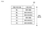
- FIG. 6 is a diagram showing collection rules 226 as an example.
- the determining unit 54 determines an unreplaceable abnormal tool as a recovery candidate with priority over a substitutable abnormal tool. As a result, tools in an abnormal state that cannot be replaced are determined as recovery candidates with higher priority.
- the determination unit 54 determines the priority of recovery candidates according to the tool state.
- a damaged tool cannot be used for machining a workpiece.
- tools whose life has expired are not recommended for use, but can still be used for machining. Therefore, damaged tools are preferably replaced preferentially over expired tools.
- the determining unit 54 determines a damaged tool that cannot be replaced as a recovery candidate with priority over a tool that cannot be replaced and has expired.
- the determination unit 54 determines the non-replaceable tool whose service life has expired, as a recovery candidate with priority over the non-replaceable tool in the service life warning state.
- the determination unit 54 also determines the priority of recovery candidates for replaceable tools in an abnormal state.
- the decision unit 54 decides a replaceable damaged tool as a recovery candidate with priority over a replaceable tool in an expired state.
- the determining unit 54 determines the substitutable tool in the end of life state as a recovery candidate with priority over the substitutable tool in the life warning state.
- the execution unit 56 executes a predetermined process for the recovery candidate tool determined by the determination unit 54 .
- the execution unit 56 controls the above-described driving unit 110 (see FIG. 2) to move the recovery candidate tool to a predetermined position.
- the control process is executed, for example, based on acceptance of collection operation by the user.
- the collection operation is received, for example, at the operation panel 400 (see FIG. 1) described above.
- FIG. 7 is a diagram showing the operation screen 410 of the operation panel 400.
- FIG. Operation screen 410 is displayed, for example, on display 405 of operation panel 400 .
- the operation screen 410 includes a display field 430, an automatic call button 440, and a selective call button 441.
- the display field 430 displays part or all of the above-described tool information 224 (see FIG. 5).
- the automatic call button 440 is a button for calling the recovery candidate tool determined by the determination unit 54 described above. More specifically, the execution unit 56 selects the tool having the highest recovery priority among the recovery candidate tools determined by the determination unit 54 based on the pressing of the automatic call button 440 on the operation screen 410. identify. Next, the execution unit 56 controls the drive unit 110 (see FIG. 2) described above to drive the identified tool to a predetermined position. After that, the operator can replace the tool moved to the predetermined position with a tool in a normal state.
- the execution unit 56 controls the drive unit 110 (see FIG. 2) described above to move the tool with the second highest recovery priority among the recovery candidate tools to a predetermined position. After that, the operator replaces the tool moved to the predetermined position with a tool in a normal state.
- the execution unit 56 moves the recovery candidate tools determined by the determination unit 54 to predetermined positions in order of priority.
- the operator can preferentially replace an abnormal tool for which there is no substitutable tool.
- the selection call button 441 is a button for calling a specific tool. The user can call the selected tool from the magazine 150 by selecting the tool information displayed in the display field 430 and pressing the select call button 441 .
- the recovery candidate tools determined by the determining unit 54 are driven to predetermined positions in order of priority. Only the tools with the highest priority for recovery may be used, or only a predetermined number of tools with higher priority for recovery may be used.
- FIG. 8 is a diagram showing an operation screen 410A according to the modification.
- the operation screen 410A shown in FIG. 8 differs from the operation screen 410 shown in FIG. 7 above in that it further includes a display field 431 and an extraction button 442. Other points are the same as operation screen 410 shown in FIG. 7, and therefore description thereof will not be repeated below.
- the execution unit 56 displays information on the recovery candidate tools determined by the determination unit 54 on the display 405 (display unit).
- the information is displayed, for example, in display field 431 of operation screen 410A.
- the information displayed in the display field 431 includes, for example, at least one of the pot number in the magazine 150, tool identification information, tool type, tool status, and remaining life of the tool.
- the execution unit 56 displays the information about the recovery candidate tools determined by the determination unit 54 in the display field 431 in order of recovery priority.
- the tool information displayed in the display field 431 is configured to be selectable. The user can call the selected tool from the magazine 150 by selecting the tool information displayed in the display column 431 and pressing the select call button 441 . This allows the user to check the tool information with the higher recovery priority and then perform the tool replacement work.
- the execution unit 56 may display only one piece of tool information with the highest recovery priority in the display field 431 .
- the execution unit 56 may display a predetermined number of pieces of tool information having a higher collection priority in the display column 431 .
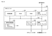
- FIG. 9 is a diagram showing an example of the hardware configuration of the CPU unit 200. As shown in FIG.
- the CPU unit 200 includes a control circuit 201 , a ROM (Read Only Memory) 202 , a RAM (Random Access Memory) 203 , a communication interface 204 and an auxiliary storage device 220 . These components are connected to internal bus 209 .
- the control circuit 201 is composed of, for example, at least one integrated circuit.
- An integrated circuit is composed of, for example, at least one CPU, at least one GPU (Graphics Processing Unit), at least one ASIC (Application Specific Integrated Circuit), at least one FPGA (Field Programmable Gate Array), or a combination thereof can be
- the control circuit 201 controls the operation of the CPU unit 200 by executing various programs such as the control program 222 .
- the control program 222 is a program for implementing functions related to the functional configurations shown in FIG. 4 described above.
- the control circuit 201 reads the control program 222 from the auxiliary storage device 220 or the ROM 202 to the RAM 203 based on the reception of the instruction to execute the control program 222 .
- the RAM 203 functions as a working memory and temporarily stores various data necessary for executing the control program 222 .
- a communication interface 204 is an interface for performing periodic communication with an external device using a field network.
- the external device includes, for example, the motor driver 111M (see FIG. 2) and the ATC driver 121A (see FIG. 2).
- As the field network for example, EtherCAT (registered trademark), EtherNet/IP (registered trademark), CC-Link (registered trademark), CompoNet (registered trademark), or the like is adopted.
- the auxiliary storage device 220 is, for example, a storage medium such as a hard disk or flash memory.
- Auxiliary storage device 220 stores control program 222, above-mentioned tool information 224, above-mentioned collection rule 226, and the like.
- control program 222 the tool information 224, and the collection rule 226 is not limited to the auxiliary storage device 220, but the storage area (eg, cache memory) of the control circuit 201, the ROM 202, the RAM 203, the external device (eg, server) or the like.
- control program 222 may be provided not as a standalone program but as part of an arbitrary program. In this case, various processes according to the present embodiment are implemented in cooperation with arbitrary programs. Even a program that does not include such a part of modules does not deviate from the gist of control program 222 according to the present embodiment. Furthermore, some or all of the functions provided by control program 222 may be implemented by dedicated hardware. Furthermore, the CPU unit 200 may be configured in the form of a so-called cloud service in which at least one server executes part of the processing of the control program 222 .
- FIG. 10 is a diagram showing an example of the hardware configuration of the CNC unit 300. As shown in FIG.
- the CNC unit 300 includes a control circuit 301, a ROM 302, a RAM 303, a communication interface 304, a communication interface 305, a fieldbus controller 306, and an auxiliary storage device 320. These components are connected to internal bus 309 .
- the control circuit 301 is composed of, for example, at least one integrated circuit.
- An integrated circuit may comprise, for example, at least one CPU, at least one ASIC, at least one FPGA, or a combination thereof.
- the control circuit 301 controls the operation of the CNC unit 300 by executing various programs such as the machining program 322 .
- the machining program 322 is a program for realizing workpiece machining.
- the control circuit 301 reads the machining program 322 from the ROM 302 to the RAM 303 based on the acceptance of the instruction to execute the machining program 322 .
- the RAM 303 functions as a working memory and temporarily stores various data necessary for executing the machining program 322 .
- a LAN, WLAN, Bluetooth (registered trademark), or the like is connected to the communication interface 304 .
- CNC unit 300 exchanges data with external devices via communication interface 304 .
- the external device includes, for example, the operation panel 400 and a server (not shown).
- a communication interface 305 is an interface for realizing communication with an external device.
- CNC unit 300 exchanges data with external devices via communication interface 305 .
- the external device includes various drive units (for example, the motor drivers 131B, 131C, 131X to 131Z, etc. described above) for machining a workpiece.
- the fieldbus controller 306 is a communication unit for realizing communication with various units connected to the fieldbus.
- An example of a unit connected to the fieldbus is the CPU unit 200 or the like.
- the auxiliary storage device 320 is, for example, a storage medium such as a hard disk or flash memory.
- the auxiliary storage device 320 stores a machining program 322 and the like.
- the storage location of the machining program 322 is not limited to the auxiliary storage device 320, and may be stored in the storage area of the control circuit 301 (eg, cache memory), ROM 302, RAM 303, external device (eg, server), etc. good.
- FIG. 11 is a diagram showing an example of the hardware configuration of the operation panel 400. As shown in FIG.
- the operation panel 400 includes a control circuit 401, a ROM (Read Only Memory) 402, a RAM (Random Access Memory) 403, a communication interface 404, a display 405, operation keys 406, and an auxiliary storage device 420. These components are connected to internal bus 409 .
- the control circuit 401 is composed of, for example, at least one integrated circuit.
- An integrated circuit may be comprised of, for example, at least one CPU, at least one GPU, at least one ASIC, at least one FPGA, or combinations thereof.
- the control circuit 401 controls the operation of the operation panel 400 by executing various programs such as the control program 422 .
- Control program 422 defines commands for controlling operation panel 400 .
- the control circuit 401 reads the control program 422 from the auxiliary storage device 420 or the ROM 402 to the RAM 403 based on the reception of the instruction to execute the control program 422 .
- the RAM 403 functions as a working memory and temporarily stores various data necessary for executing the control program 422 .
- the communication interface 404 is a communication unit for realizing communication using a LAN (Local Area Network) cable, WLAN, Bluetooth (registered trademark), or the like.
- the operation panel 400 realizes communication with external devices such as the CNC unit 300 described above via the communication interface 404 .
- the display 405 is, for example, a liquid crystal display, an organic EL display, or other display equipment.
- the display 405 sends an image signal for displaying an image to the display 405 according to a command from the control circuit 401 or the like.
- the display 405 is configured by a touch panel, for example, and receives various operations for the machine tool 100 by touch operations.
- the operation key 406 is composed of a plurality of hardware keys and accepts various user operations on the operation panel 400. A signal corresponding to the pressed key is output to the control circuit 401 .
- the auxiliary storage device 420 is, for example, a storage medium such as a hard disk or flash memory.
- Auxiliary storage device 420 stores a control program 422 and the like.
- the storage location of the control program 422 is not limited to the auxiliary storage device 420, but may be stored in the storage area of the control circuit 401 (for example, cache memory), ROM 402, RAM 403, external equipment (for example, server), or the like.
- FIG. 12 is a flowchart showing part of the processing executed by control unit 50 of machine tool 100 .
- the processing shown in FIG. 12 is implemented by the control unit 50 executing the above-described control program 222 (see FIG. 9) and the like. In other aspects, part or all of the processing may be performed by circuit elements or other hardware.
- step S110 the control unit 50 determines whether or not an operation to extract recovery candidate tools from among the tools held in the magazine 150 has been received.
- the extraction operation is accepted, for example, based on pressing of the extraction button 442 (see FIG. 8) described above. If control unit 50 determines that an operation for extracting recovery candidate tools has been accepted (YES in step S110), control unit 50 switches control to step S112. Otherwise (NO in step S110), control unit 50 executes the process of step S110 again.
- the control unit 50 acquires the above-described tool information 224 (see FIG. 5).
- the tool information 224 defines information for each tool held in the magazine 150 .
- step S114 the control unit 50 functions as the above-described determination unit 54 (see FIG. 4), and based on the tool information 224 acquired in step S112, selects collection candidates from among the tools held in the magazine 150. Decide on tools. Since the method of determining the recovery candidate tools is as described above, the description thereof will not be repeated.
- step S116 the control unit 50 functions as the execution unit 56 (see FIG. 4) described above, and displays the tool information related to the recovery candidate tool determined in step S114 in the display field 431 of the operation screen 410A. .
- step S120 the control unit 50 determines whether or not a call operation has been received for the recovery candidate tool. As an example, the control unit 50 determines that the call operation has been accepted based on the selection of one or more pieces of tool information displayed in the display field 431 and the pressing of the selection call button 441 on the operation screen 410A. do. If control unit 50 determines that a call operation has been received for the collection candidate tool (YES in step S120), control is switched to step S122. Otherwise (NO in step S120), control unit 50 switches control to step S130.
- step S122 the control unit 50 functions as the execution unit 56 (see FIG. 4) described above, and moves the recovery candidate tool selected in the display field 431 of the operation screen 410A to a predetermined position. After that, the control unit 50 terminates the processing shown in FIG. 12 .
- step S130 the control unit 50 determines whether or not a cancel operation has been accepted.
- the cancel operation is accepted, for example, when a cancel button (not shown) provided on the operation screen 410A is pressed. Alternatively, the cancel operation is accepted based on pressing of a button (not shown) for closing the operation screen 410A.
- control unit 50 determines that a cancel operation has been received (YES in step S130), it ends the processing shown in FIG. Otherwise (NO in step S130), control unit 50 returns the control to step S120.
- the machine tool 100 acquires the tool information 224 regarding each tool held in the magazine 150 .
- the tool information 224 defines at least the type of each tool held in the magazine 150 and the state of each tool.
- the states include, for example, the above-described normal state and the above-described abnormal state.
- the control unit 50 determines an abnormal tool for which there is no normal tool of the same type in the magazine 150 as a collection candidate. As a result, the control unit 50 preferentially selects a tool for which no substitutable tool exists as a recovery candidate over a tool for which a substitutable tool exists.
- the machine tool 100 can more appropriately determine the priority of the tools to be collected according to the presence or absence of substitutable tools. As a result, the machine tool 100 can avoid stopping the machining of the workpiece. Alternatively, even if the machining of the work has stopped, the machine tool 100 can restart the machining of the work more quickly.
Landscapes
- Engineering & Computer Science (AREA)
- Mechanical Engineering (AREA)
- Numerical Control (AREA)
- Automatic Tool Replacement In Machine Tools (AREA)
Abstract
Description
まず、図1を参照して、実施の形態に従う工作機械100について説明する。図1は、工作機械100の外観を示す図である。
次に、図2を参照して、工作機械100の各種構成について説明する。図2は、工作機械100の駆動機構の一例を示す図である。
図3を参照して、工具の回収処理の概略について説明する。図3は、上述のマガジン150に保持されている工具の中から回収候補を決定する処理を概略的に示す図である。
次に、図4~図7を参照して、工作機械100の機能構成について説明する。図4は、工作機械100の機能構成の一例を示す図である。
まず、図5を参照して、図4に示される監視部52の機能について説明する。
次に、図6を参照して、図4に示される決定部54の機能について説明する。
次に、図7を参照して、図4に示される実行部56の機能について説明する。実行部56は、決定部54によって決定された回収候補の工具に関して予め定められた処理を実行する。
次に、図8を参照して、上述の操作画面410の変形例について説明する。図8は、変形例に従う操作画面410Aを示す図である。
図9を参照して、上述の図2に示されるCPUユニット200のハードウェア構成について説明する。図9は、CPUユニット200のハードウェア構成の一例を示す図である。
次に、図10を参照して、上述の図2に示されるCNCユニット300のハードウェア構成について説明する。図10は、CNCユニット300のハードウェア構成の一例を示す図である。
次に、図11を参照して、上述の図2に示される操作盤400のハードウェア構成について説明する。図11は、操作盤400のハードウェア構成の一例を示す図である。
次に、図12を参照して、工作機械100の制御構造について説明する。図12は、工作機械100の制御部50が実行する処理の一部を表わすフローチャートである。
以上のようにして、工作機械100は、マガジン150に保持されている各工具に関する工具情報224を取得する。工具情報224は、マガジン150に保持されている各工具の種別と、当該各工具の状態とを少なくとも規定している。当該状態は、たとえば、上述の正常状態と上述の異常状態とを含む。次に、制御部50は、当該取得した工具情報224に基づいて、正常状態である同種の工具がマガジン150内に存在しない異常状態の工具を回収候補として決定する。これにより、制御部50は、代用可能な工具が存在する工具よりも代用可能な工具が存在しない工具を優先して回収候補とする。
Claims (8)
- 工作機械であって、
複数の工具を保持することが可能なマガジンと、
前記複数の工具の内の少なくとも1つの工具を用いてワークを加工するための加工機本体と、
前記工作機械を制御するための制御部とを備え、
前記制御部は、
前記複数の工具に関する工具情報を取得する処理を実行し、前記工具情報は、前記複数の工具の各々について工具の種別と工具の状態とを規定しており、前記状態は、異常状態と正常状態とを含み、
前記制御部は、さらに、
前記工具情報に基づいて、前記正常状態である同種の工具が前記マガジン内に存在しない前記異常状態の工具を回収候補として決定する処理と、
前記回収候補の工具に関する予め定められた処理とを実行する、工作機械。 - 前記工作機械は、さらに、前記マガジンを駆動するための駆動部を備え、
前記予め定められた処理は、前記回収候補の工具を予め定められた位置に移動するように前記駆動部を制御する処理を含む、請求項1に記載の工作機械。 - 前記工作機械は、さらに、表示部を備え、
前記予め定められた処理は、前記回収候補の工具に関する情報を前記表示部に表示する処理を含む、請求項1または2に記載の工作機械。 - 前記異常状態は、
工具が損傷していることを示す損傷状態と、
工具の寿命が尽きていることを示す寿命切れ状態とを含み、
前記決定する処理は、前記正常状態である同種の工具が前記マガジン内に存在しない前記損傷状態の工具を、前記正常状態である同種の工具が前記マガジン内に存在しない前記寿命切れ状態の工具よりも、優先的に前記回収候補として決定する、請求項1~3のいずれか1項に記載の工作機械。 - 前記異常状態は、さらに、工具の寿命が尽きておらず、かつ、工具の残寿命が所定閾値よりも少ないことを示す寿命警告状態を含み、
前記決定する処理では、前記正常状態である同種の工具が前記マガジン内に存在しない前記寿命切れ状態の工具が、前記正常状態である同種の工具が前記マガジン内に存在しない前記寿命警告状態の工具よりも、優先的に前記回収候補として決定される、請求項4に記載の工作機械。 - 前記決定する処理では、前記正常状態である同種の工具が前記マガジン内に存在しない前記異常状態の工具が、前記正常状態である同種の工具が前記マガジン内に存在する前記異常状態の工具よりも、優先的に前記回収候補として決定される、請求項1~3のいずれか1項に記載の工作機械。
- 工作機械の制御方法であって、
前記工作機械は、
複数の工具を保持することが可能なマガジンと、
前記複数の工具の内の少なくとも1つの工具を用いてワークを加工するための加工機本体とを備え、
前記制御方法は、
前記複数の工具に関する工具情報を取得するステップを備え、前記工具情報は、前記複数の工具の各々について工具の種別と工具の状態とを規定しており、前記状態は、異常状態と正常状態とを含み、
前記制御方法は、さらに、
前記工具情報に基づいて、前記正常状態である同種の工具が前記マガジン内に存在しない前記異常状態の工具を回収候補として決定するステップと、
前記回収候補の工具に関する予め定められた処理を実行するステップと備える、制御方法。 - 工作機械の制御プログラムであって、
前記工作機械は、
複数の工具を保持することが可能なマガジンと、
前記複数の工具の内の少なくとも1つの工具を用いてワークを加工するための加工機本体とを備え、
前記制御プログラムは、前記工作機械に、
前記複数の工具に関する工具情報を取得するステップを実行させ、前記工具情報は、前記複数の工具の各々について工具の種別と工具の状態とを規定しており、前記状態は、異常状態と正常状態とを含み、
前記制御プログラムは、前記工作機械に、さらに、
前記工具情報に基づいて、前記正常状態である同種の工具が前記マガジン内に存在しない前記異常状態の工具を回収候補として決定するステップと、
前記回収候補の工具に関する予め定められた処理とを実行させる、制御プログラム。
Priority Applications (4)
| Application Number | Priority Date | Filing Date | Title |
|---|---|---|---|
| PCT/JP2021/033695 WO2023042249A1 (ja) | 2021-09-14 | 2021-09-14 | 工作機械、制御方法、および制御プログラム |
| EP21957433.2A EP4403299A1 (en) | 2021-09-14 | 2021-09-14 | Machine tool, control method, and control program |
| JP2023547956A JPWO2023042249A1 (ja) | 2021-09-14 | 2021-09-14 | |
| CN202180102304.7A CN117999149A (zh) | 2021-09-14 | 2021-09-14 | 机床、控制方法以及控制程序 |
Applications Claiming Priority (1)
| Application Number | Priority Date | Filing Date | Title |
|---|---|---|---|
| PCT/JP2021/033695 WO2023042249A1 (ja) | 2021-09-14 | 2021-09-14 | 工作機械、制御方法、および制御プログラム |
Publications (1)
| Publication Number | Publication Date |
|---|---|
| WO2023042249A1 true WO2023042249A1 (ja) | 2023-03-23 |
Family
ID=85601940
Family Applications (1)
| Application Number | Title | Priority Date | Filing Date |
|---|---|---|---|
| PCT/JP2021/033695 WO2023042249A1 (ja) | 2021-09-14 | 2021-09-14 | 工作機械、制御方法、および制御プログラム |
Country Status (4)
| Country | Link |
|---|---|
| EP (1) | EP4403299A1 (ja) |
| JP (1) | JPWO2023042249A1 (ja) |
| CN (1) | CN117999149A (ja) |
| WO (1) | WO2023042249A1 (ja) |
Cited By (1)
| Publication number | Priority date | Publication date | Assignee | Title |
|---|---|---|---|---|
| KR102629698B1 (ko) * | 2023-09-11 | 2024-01-25 | (재)대구기계부품연구원 | 기상측정을 이용한 공구의 마모량 예측방법 및 예측 시스템 |
Citations (8)
| Publication number | Priority date | Publication date | Assignee | Title |
|---|---|---|---|---|
| JPS61178151A (ja) * | 1985-02-01 | 1986-08-09 | Yamazaki Mazak Corp | 数値制御装置 |
| JPH0643920A (ja) * | 1992-07-23 | 1994-02-18 | Fanuc Ltd | 工具管理方式 |
| JPH10100033A (ja) * | 1996-09-30 | 1998-04-21 | Toyoda Mach Works Ltd | 工具選択方法および該方法を用いた工作機械 |
| JP2000084775A (ja) * | 1998-09-08 | 2000-03-28 | Toyoda Mach Works Ltd | 工具マガジン装置 |
| JP2004130451A (ja) | 2002-10-10 | 2004-04-30 | Toyota Motor Corp | 工具交換時期表示装置 |
| KR20130068737A (ko) * | 2011-12-16 | 2013-06-26 | 두산인프라코어 주식회사 | 공구 매거진의 공구 상태 확인 장치 및 방법 |
| WO2020012547A1 (ja) * | 2018-07-10 | 2020-01-16 | 三菱電機株式会社 | 数値制御装置 |
| JP6775704B1 (ja) * | 2020-07-28 | 2020-10-28 | Dmg森精機株式会社 | 工具セットアップ装置、工具セットアップ装置の制御方法、および工具セットアップ装置の制御プログラム |
-
2021
- 2021-09-14 EP EP21957433.2A patent/EP4403299A1/en active Pending
- 2021-09-14 CN CN202180102304.7A patent/CN117999149A/zh active Pending
- 2021-09-14 WO PCT/JP2021/033695 patent/WO2023042249A1/ja active Application Filing
- 2021-09-14 JP JP2023547956A patent/JPWO2023042249A1/ja active Pending
Patent Citations (8)
| Publication number | Priority date | Publication date | Assignee | Title |
|---|---|---|---|---|
| JPS61178151A (ja) * | 1985-02-01 | 1986-08-09 | Yamazaki Mazak Corp | 数値制御装置 |
| JPH0643920A (ja) * | 1992-07-23 | 1994-02-18 | Fanuc Ltd | 工具管理方式 |
| JPH10100033A (ja) * | 1996-09-30 | 1998-04-21 | Toyoda Mach Works Ltd | 工具選択方法および該方法を用いた工作機械 |
| JP2000084775A (ja) * | 1998-09-08 | 2000-03-28 | Toyoda Mach Works Ltd | 工具マガジン装置 |
| JP2004130451A (ja) | 2002-10-10 | 2004-04-30 | Toyota Motor Corp | 工具交換時期表示装置 |
| KR20130068737A (ko) * | 2011-12-16 | 2013-06-26 | 두산인프라코어 주식회사 | 공구 매거진의 공구 상태 확인 장치 및 방법 |
| WO2020012547A1 (ja) * | 2018-07-10 | 2020-01-16 | 三菱電機株式会社 | 数値制御装置 |
| JP6775704B1 (ja) * | 2020-07-28 | 2020-10-28 | Dmg森精機株式会社 | 工具セットアップ装置、工具セットアップ装置の制御方法、および工具セットアップ装置の制御プログラム |
Cited By (1)
| Publication number | Priority date | Publication date | Assignee | Title |
|---|---|---|---|---|
| KR102629698B1 (ko) * | 2023-09-11 | 2024-01-25 | (재)대구기계부품연구원 | 기상측정을 이용한 공구의 마모량 예측방법 및 예측 시스템 |
Also Published As
| Publication number | Publication date |
|---|---|
| EP4403299A1 (en) | 2024-07-24 |
| JPWO2023042249A1 (ja) | 2023-03-23 |
| CN117999149A (zh) | 2024-05-07 |
Similar Documents
| Publication | Publication Date | Title |
|---|---|---|
| EP1758004B1 (en) | NC Machine Tool | |
| EP3309637B1 (en) | Control system for controlling operation of a numerically controlled machine tool, and back-end and front-end control devices for use in such system | |
| US9778646B2 (en) | Robot controller for controlling robot which supplies and discharges workpiece | |
| JP6569825B1 (ja) | 数値制御装置 | |
| US20220378560A1 (en) | Dental machining system for predicting the wear condition of a dental tool | |
| WO2023042249A1 (ja) | 工作機械、制御方法、および制御プログラム | |
| JP2021142613A (ja) | 工具管理システム、工具寸法測定装置、および端末 | |
| JP7001855B1 (ja) | 工具搬送システム、工具搬送システムの制御方法、および工具搬送システムの制御プログラム | |
| CN114667202A (zh) | 数控装置、机器学习装置及数控方法 | |
| JP7017537B2 (ja) | 工作機械、加工システムおよび管理システム | |
| JP2021109289A (ja) | 工作機械、工作機械の制御方法、および工作機械の制御プログラム | |
| US20230415287A1 (en) | Tool Transport System, Control Method for Tool Transport System, and Control Program for Tool Transport System | |
| KR20190051154A (ko) | 공구 매거진의 이상 공구 교환방법 | |
| US20240217043A1 (en) | Tool transfer system, control method, and control program | |
| JPS6199529A (ja) | パンチプレスの工具寿命管理装置 | |
| JP2004054701A (ja) | 機械の稼働状況監視システム並びに数値制御装置及びプログラム | |
| JP7001854B1 (ja) | 工具搬送システム、工具搬送システムの制御方法、および工具搬送システムの制御プログラム | |
| JP7055928B1 (ja) | 工作機械、制御方法、および制御プログラム | |
| JP7088742B2 (ja) | 加工システム、加工機、加工機の制御方法及びプログラム | |
| EP4068020A1 (en) | Display control system | |
| JP6966604B1 (ja) | 工作機械、工作機械の制御方法、および、工作機械の制御プログラム | |
| WO2023199408A1 (ja) | 数値制御装置およびコンピュータ読み取り可能な記憶媒体 | |
| KR100254185B1 (ko) | 공작기계의가공공구확인방법 | |
| JP2023067294A (ja) | ワーク加工装置 | |
| JP2022131366A (ja) | 工作機械、表示制御方法、および表示制御プログラム |
Legal Events
| Date | Code | Title | Description |
|---|---|---|---|
| 121 | Ep: the epo has been informed by wipo that ep was designated in this application |
Ref document number: 21957433 Country of ref document: EP Kind code of ref document: A1 |
|
| WWE | Wipo information: entry into national phase |
Ref document number: 2023547956 Country of ref document: JP |
|
| WWE | Wipo information: entry into national phase |
Ref document number: 202180102304.7 Country of ref document: CN |
|
| WWE | Wipo information: entry into national phase |
Ref document number: 2021957433 Country of ref document: EP |
|
| NENP | Non-entry into the national phase |
Ref country code: DE |
|
| ENP | Entry into the national phase |
Ref document number: 2021957433 Country of ref document: EP Effective date: 20240415 |