WO2023037693A1 - 生産管理方法、生産管理装置及びプログラム - Google Patents
生産管理方法、生産管理装置及びプログラム Download PDFInfo
- Publication number
- WO2023037693A1 WO2023037693A1 PCT/JP2022/024702 JP2022024702W WO2023037693A1 WO 2023037693 A1 WO2023037693 A1 WO 2023037693A1 JP 2022024702 W JP2022024702 W JP 2022024702W WO 2023037693 A1 WO2023037693 A1 WO 2023037693A1
- Authority
- WO
- WIPO (PCT)
- Prior art keywords
- production
- time
- maintenance
- degree
- malfunction
- Prior art date
- Legal status (The legal status is an assumption and is not a legal conclusion. Google has not performed a legal analysis and makes no representation as to the accuracy of the status listed.)
- Ceased
Links
Images






Classifications
-
- G—PHYSICS
- G05—CONTROLLING; REGULATING
- G05B—CONTROL OR REGULATING SYSTEMS IN GENERAL; FUNCTIONAL ELEMENTS OF SUCH SYSTEMS; MONITORING OR TESTING ARRANGEMENTS FOR SUCH SYSTEMS OR ELEMENTS
- G05B19/00—Program-control systems
- G05B19/02—Program-control systems electric
- G05B19/418—Total factory control, i.e. centrally controlling a plurality of machines, e.g. direct or distributed numerical control [DNC], flexible manufacturing systems [FMS], integrated manufacturing systems [IMS] or computer integrated manufacturing [CIM]
-
- G—PHYSICS
- G06—COMPUTING OR CALCULATING; COUNTING
- G06Q—INFORMATION AND COMMUNICATION TECHNOLOGY [ICT] SPECIALLY ADAPTED FOR ADMINISTRATIVE, COMMERCIAL, FINANCIAL, MANAGERIAL OR SUPERVISORY PURPOSES; SYSTEMS OR METHODS SPECIALLY ADAPTED FOR ADMINISTRATIVE, COMMERCIAL, FINANCIAL, MANAGERIAL OR SUPERVISORY PURPOSES, NOT OTHERWISE PROVIDED FOR
- G06Q50/00—Information and communication technology [ICT] specially adapted for implementation of business processes of specific business sectors, e.g. utilities or tourism
- G06Q50/04—Manufacturing
-
- H—ELECTRICITY
- H05—ELECTRIC TECHNIQUES NOT OTHERWISE PROVIDED FOR
- H05K—PRINTED CIRCUITS; CASINGS OR CONSTRUCTIONAL DETAILS OF ELECTRIC APPARATUS; MANUFACTURE OF ASSEMBLAGES OF ELECTRICAL COMPONENTS
- H05K13/00—Apparatus or processes specially adapted for manufacturing or adjusting assemblages of electric components
- H05K13/08—Monitoring manufacture of assemblages
- H05K13/0895—Maintenance systems or processes, e.g. indicating need for maintenance
-
- Y—GENERAL TAGGING OF NEW TECHNOLOGICAL DEVELOPMENTS; GENERAL TAGGING OF CROSS-SECTIONAL TECHNOLOGIES SPANNING OVER SEVERAL SECTIONS OF THE IPC; TECHNICAL SUBJECTS COVERED BY FORMER USPC CROSS-REFERENCE ART COLLECTIONS [XRACs] AND DIGESTS
- Y02—TECHNOLOGIES OR APPLICATIONS FOR MITIGATION OR ADAPTATION AGAINST CLIMATE CHANGE
- Y02P—CLIMATE CHANGE MITIGATION TECHNOLOGIES IN THE PRODUCTION OR PROCESSING OF GOODS
- Y02P90/00—Enabling technologies with a potential contribution to greenhouse gas [GHG] emissions mitigation
- Y02P90/02—Total factory control, e.g. smart factories, flexible manufacturing systems [FMS] or integrated manufacturing systems [IMS]
Definitions
- the present disclosure relates to a production control method, production control device and program.
- Patent Literature 1 discloses a technique for creating a recovery plan for making up for the delay in the production plan caused by repairing the failure when a failure occurs in the production equipment.
- Patent Document 1 has a large impact on the production plan because production is stopped and repairs are carried out.
- Patent Document 1 discloses recovering the influence (delay) on the production plan caused by the repair, it does not disclose how to suppress the influence on the production plan itself.
- the present disclosure provides a production control method, a production control device, and a program capable of suppressing the impact on the production plan even when the production device malfunctions.
- a production management method is a production management method executed by a production management device that controls a production device, wherein the production device that has experienced a malfunction during production continues production in a first operation pattern.
- a first impact level indicating the impact on the production plan in the event of a malfunction is specified, and a second impact level indicating the impact on the production plan when maintenance of the production equipment in which the malfunction has occurred is performed during the production.
- a recommended timing for performing the maintenance is determined based on the first degree of impact and the second degree of impact, and maintenance information including the determined recommended timing is output.
- a production management apparatus is a production management apparatus that controls a production apparatus, and is a production management apparatus that is adapted to a production plan when the production apparatus that malfunctions during production continues production in a first operation pattern.
- a first identifying unit that identifies a first degree of influence indicating an influence, and a second degree of influence that indicates an influence on the production plan when maintenance of the production apparatus in which the malfunction has occurred is performed during the production.
- a second identifying unit a determining unit that determines a recommended timing for performing the maintenance based on the first impact level and the second impact level, and an output that outputs maintenance information including the determined recommended timing and a part.
- a program according to one aspect of the present disclosure is a program for causing a computer to execute the production control method described above.
- FIG. 1 is a diagram showing a schematic configuration of a production management system according to an embodiment.
- FIG. 2 is a block diagram showing the functional configuration of the production management system according to the embodiment.
- FIG. 3 is a first diagram showing an outline of a production control method by a server according to the embodiment.
- FIG. 4 is a second diagram showing an outline of the production control method by the server according to the embodiment.
- FIG. 5 is a diagram illustrating an example of a production time database according to the embodiment;
- FIG. 6 is a diagram illustrating an example of a maintenance time database according to the embodiment;
- FIG. 7 is a sequence diagram showing operations of the production management system according to the embodiment.
- FIG. 8 is a flow chart showing the operation of the production device according to the embodiment.
- FIG. 1 is a diagram showing a schematic configuration of a production management system according to an embodiment.
- FIG. 2 is a block diagram showing the functional configuration of the production management system according to the embodiment.
- FIG. 3 is a first diagram showing an
- FIG. 9 is a diagram illustrating an example of resource information according to the embodiment.
- FIG. 10 is a diagram showing the relationship between the failure location and the execution feasibility of countermeasures according to the embodiment.
- FIG. 11 is a flow chart showing operation of the server according to the embodiment.
- FIG. 12 is a flow chart showing details of step S203 shown in FIG.
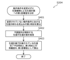
- FIG. 13 is a flow chart showing details of step S204 shown in FIG.
- FIG. 14 is a flow chart showing details of step S205 shown in FIG.
- a production management method is a production management method executed by a production management device that controls a production device, wherein the production device that has experienced a malfunction during production continues production in a first operation pattern.
- a first impact level indicating the impact on the production plan in the event of a malfunction is specified, and a second impact level indicating the impact on the production plan when maintenance of the production equipment in which the malfunction has occurred is performed during the production.
- a recommended timing for performing the maintenance is determined based on the first degree of impact and the second degree of impact, and maintenance information including the determined recommended timing is output.
- the recommended timing for performing maintenance can be determined based on the first degree of impact and the second degree of impact.
- the production plan includes at least a production period for producing a predetermined amount of works, and in determining the recommended timing, if the first impact is smaller than the second impact, the first operation pattern
- the recommended timing may be determined as the timing after the production of the predetermined amount is completed by continuing the production.
- the timing after production can be determined as the recommended timing. Therefore, even if the production equipment malfunctions, if the first influence degree is smaller than the second influence degree, the influence on the production plan can be suppressed.
- the timing during production may be determined as the recommended timing.
- the timing during production can be determined as the recommended timing. Therefore, even if the production equipment malfunctions, if the first influence degree is equal to or higher than the second influence degree, the influence on the production plan can be suppressed.
- a first time at which the production of the predetermined amount is completed when the production is continued in the first operation pattern is identified, and based on the production plan, the production A scheduled time that is a time when the period is scheduled to end may be specified, and the first degree of impact may be specified based on the first time and the scheduled time.
- the first degree of influence can be easily specified simply by specifying the first time and the scheduled time.
- a production time database that manages the time required for production in association with the current time, The first time may be specified.
- the first time can be easily specified based on the production time database and the current time.
- a first time required for the production when the production is continued with the first operation pattern is specified, the first time is added to the current time, and the A first time may be specified.
- the first time required for production when production is continued with the first operation pattern is specified, so the first time can be specified accurately.
- a second time at which the production is completed when the production is stopped and the maintenance is performed at the timing when the malfunction occurs in the production device is specified, and the A scheduled time, which is a time when the production is scheduled to be completed, may be specified based on the production plan, and the second degree of impact may be specified based on the second time and the scheduled time.
- the second degree of influence can be easily identified by simply identifying the second time and the scheduled time.
- a maintenance completion time indicating the time at which the maintenance is expected to be completed is identified, and a second time required until the production is completed is identified based on the production plan.
- the second time may be calculated by adding the second time to the maintenance completion time.
- the second time can be accurately specified based on the maintenance completion time and the second time.
- the start time at which the maintenance can be started is specified based on resource information indicating the resources required when performing maintenance on the production apparatus, and the time required to complete the maintenance is specified.
- a maintenance time indicating time may be specified, and the maintenance completion time may be specified based on the start time and the maintenance time.
- an identifier specifying a malfunctioning location of the production apparatus and status information indicating a state of the malfunctioning location are further acquired, and an identifier identifying each location of the production device and the status of each location are acquired.
- information, a maintenance time database that associates and manages the time required for maintenance to be completed according to the state of each location, and the maintenance time based on the acquired identifier and the state information. may be specified.
- the maintenance completion time may be specified by adding the maintenance time to the start time.
- the maintenance completion time can be easily identified without using special calculations.
- the resource information may include information about a time slot that can be secured by the worker performing the maintenance, and the start time may be specified based on the information about the time slot.
- the recommended timing when performing the maintenance during the production may be the timing when the malfunction occurs or the timing when the resource can be secured.
- the first operation pattern may be any of the same operation pattern as before the malfunction, an operation pattern for changing the operation conditions of the malfunctioning portion of the production apparatus, and an operation pattern for canceling the use of the malfunctioning portion. or one.
- the production equipment operates after the failure in any of the same operation pattern as before the failure, the operation pattern for changing the operation conditions of the failure location of the production equipment, and the operation pattern for canceling the use of the failure location. It is possible to specify the first influence degree according to the operation pattern after the malfunction of the production equipment.
- the production apparatus before the malfunction occurs is producing with a second operation pattern
- the first influence degree is the same as the second operation pattern
- the and a fourth influence that is the influence when the first operation pattern and the second operation pattern are different
- the recommended timing may be determined based on the degree of influence, or based on the fourth degree of influence and the second degree of influence.
- the fourth impact may be specified as the first impact.
- a production management apparatus is a production management apparatus that controls a production apparatus, and is a production plan for a case where the production apparatus that has experienced a malfunction during production continues production in a first operation pattern. and a second impact level indicating the impact on the production plan when maintenance of the production equipment in which the malfunction occurred is performed during the production.
- a determining unit that determines a recommended timing for performing the maintenance based on the first impact level and the second impact level; and outputs maintenance information including the determined recommended timing.
- an output unit for A program according to an aspect of the present disclosure is a program for causing a computer to execute the production control method described above.
- these general or specific aspects may be realized by a system, method, integrated circuit, computer program, or non-transitory recording medium such as a computer-readable CD-ROM. It may be realized by any combination of circuits, computer programs or recording media.
- the program may be pre-stored in a recording medium, or may be supplied to the recording medium via a wide area network including the Internet.
- each figure is a schematic diagram and is not necessarily strictly illustrated. Therefore, for example, scales and the like do not necessarily match in each drawing. Moreover, in each figure, the same code
- FIG. 1 A production control method and the like according to the present embodiment will be described below with reference to FIGS. 1 to 14.
- FIG. 1 A production control method and the like according to the present embodiment will be described below with reference to FIGS. 1 to 14.
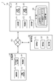
- FIG. 1 is a diagram showing a schematic configuration of a production management system 1 according to this embodiment.
- the production management system 1 includes a production device 10, a server 20, a display device 30, and a network 40.
- the production device 10, the server 20, and the display device 30 are connected to each other via a network 40 so as to be able to communicate with each other.
- the production management system 1 is a system for the server 20 to control the production equipment 10 to carry out production according to a preset production plan.
- the production apparatus 10 is a production line that performs predetermined processing on objects (workpieces) such as substrates.
- the production apparatus 10 includes a component mounting apparatus that mounts components on a substrate.
- the production apparatus 10 produces mounted boards on which components are mounted by, for example, performing solder printing work, component mounting work, reflow work, and the like on the boards brought in from the upstream side, and the manufactured mounted boards are manufactured. Carry out downstream. Mounting is, for example, component mounting, but is not limited to this.
- a component mounting apparatus includes, for example, a transport unit that transports a substrate, a feeder that supplies components to be mounted on the substrate, and a mounting head ( head), a moving unit for moving the head, and the like.
- the transport section is configured including, for example, one or more transport lanes.
- a plurality of nozzles are attached to the head, for example.
- the production apparatus 10 further includes a flow rate sensor for measuring the flow rate of air flowing inside the nozzle, a component for determining whether or not the nozzle has picked up a component, and calculating the amount of deviation of the picked up position of the picked component. It may also have a sensor, such as a recognition camera, to detect nozzle malfunction. Moreover, the production apparatus 10 may have various sensors capable of detecting malfunctions of other components (for example, units) such as the head, the transport section, the feeder, the head, and the moving section. In addition, the production apparatus 10 may detect a malfunction of the unit including the nozzle based on the inspection result of an inspection apparatus that inspects the product adjacent to the production apparatus 10 . Note that the configuration of the production apparatus 10 is not limited to the above, and is appropriately determined according to the types and shapes of the target object and parts, the processing method, and the like.
- the object is not limited to a substrate, and may be any object that can be processed in a predetermined manner.
- the target object may be, for example, a flat plate-like object (for example, an iron plate) or other objects.
- mounting a component is an example of predetermined processing, the predetermined processing is not limited to mounting a component.
- the predetermined processing may be fixing the component to the substrate by locking or crimping (for example, thermocompression) the component, or curing the object applied to the object by heat or light. It may be a mechanical process such as deforming or cutting at least a part of the object.
- the server 20 is an information processing device that manages production in the production management system 1.
- the server 20 controls production in the production apparatus 10, for example, based on a pre-obtained production plan.
- the production plan includes production quantity (e.g. production quantity), production period (e.g. production start time and production end time), part identification information, part quantity to be used, etc., but at least the board It is only necessary to include a production period during which a predetermined amount is produced.
- the server 20 includes a communication interface for communicating with the production device 10 and the display device 30, a volatile memory as a temporary storage area for executing programs, an input/output port for transmitting and receiving signals, and executing programs. It is implemented by a computer having a processor or the like that Server 20 is an example of a production management device that controls production device 10 .
- the server 20 may be located in the factory (an example of the facility) where the production device 10 is located, or may be located in a remote location different from the factory.
- the display device 30 includes a display panel such as a liquid crystal panel or an organic EL panel, and presents information acquired from the server 20 as an image.
- a display panel such as a liquid crystal panel or an organic EL panel
- the production control system 1 may include a sound output device that presents information from the server 20 by voice instead of or together with the display device 30 . Also, the presentation method is not limited to display or sound.
- the display device 30 may be a stationary device or a portable device.
- the display device 30 may be implemented by, for example, a display unit of a mobile terminal owned by an operator. Moreover, the display device 30 may be provided in the production device 10 .
- the network 40 connects the production device 10, the server 20, and the display device 30 so that they can communicate with each other.
- the network 40 may be realized by a wide area communication network such as the Internet, or may be realized by a short-range wireless network such as a wireless LAN (Local Area Network). Further, the communication among the production device 10, the server 20, and the display device 30 may be performed by wireless communication, or may be performed by wired communication.
- FIG. 2 is a block diagram showing the functional configuration of the production management system 1 according to this embodiment.
- the production apparatus 10 has a communication section 11, a state detection section 12, an operating condition change section 13, and a control section 14 in addition to the component mounting device.
- the communication unit 11, the state detection unit 12, the operating condition change unit 13, and the control unit 14 are, for example, processing units mounted on the production apparatus 10, and are realized by, for example, processors.
- the processor operates according to a program (computer program) stored in a storage unit (not shown) to implement various functions of the processing unit.
- the communication unit 11 communicates with the server 20 and the display device 30 via the network 40.
- the communication unit 11 includes a communication module (communication circuit).
- the state detection unit 12 detects the state of components for processing parts in the production apparatus 10 .
- the status includes that the component is normal and that the component is unhealthy.
- the state detection unit 12 detects malfunction of each component of the component mounting apparatus, for example, based on measurement results from various sensors.
- the state detection unit 12 detects, for example, the component in which malfunction has occurred and the state of the malfunction.
- the constituent parts (malfunction locations) where malfunctions occur are, for example, nozzles, heads, feeders, conveying units, light sources, etc., but are not limited to these.
- a malfunction is a state in which the production performance of the production apparatus 10 is degraded, for example, a state in which at least one of the components cannot exhibit its original production performance, or a state in which it does not operate (does not function).
- Malfunctions may also include conditions or failures that are within the range of normal production performance but are predicted to be unable to exhibit original production performance in the future.
- the malfunction may include, for example, at least one of a malfunction that is currently occurring and a malfunction that is predicted to occur in the future (for example, within a predetermined time period from the current time).
- the detection of a malfunction may include, for example, at least one of detecting a currently occurring malfunction and detecting a trend of the malfunction. Detecting a trend of malfunction includes detecting a malfunction predicted to occur in the future. Prediction of malfunction may be performed based on, for example, the slope of the measurement result of the sensor (degree of change in time-series data).
- the state detection unit 12 may determine that there is a tendency to malfunction when the measurement result obtained from the sensor deviates from the normal tendency. Further, the state detection unit 12 may determine that there is a tendency to malfunction when the error rate or the number of errors indicated in the measurement result is increasing, for example. For example, if the malfunctioning part is a nozzle, the malfunction may be, for example, nozzle clogging, nozzle bending, or nozzle contamination.
- detecting a malfunction means simply determining the presence or absence of a malfunction, determining that a phenomenon that satisfies a predetermined condition is malfunction, or predicting that a malfunction will occur in the future.
- the operating condition changing unit 13 changes the operating conditions of the production apparatus 10 (for example, the operation conditions). Note that even if the production performance measured in the production apparatus 10 is normal, the operating conditions may be changed according to the state of the measured production performance.
- server 20 may have the function of the operating condition changing unit 13 .
- operating conditions are also described as operating patterns.
- the control unit 14 is a control device that controls each component of the production device 10 .
- the control unit 14 controls the component mounting apparatus based on, for example, a production plan.
- the control section 14 controls the operation of the component mounting apparatus based on the operating conditions changed by the operating condition changing section 13 .
- the server 20 has a communication section 21 , a control section 22 , an analysis section 23 , a countermeasure determination section 24 , an information generation section 25 and a storage section 26 .
- the processor operates according to a program (computer program) stored in the storage unit 26 to implement various functions of the processing unit.
- the communication unit 21 communicates with the production device 10 and the display device 30 via the network 40.
- the communication unit 21 outputs the information generated by the information generation unit 25 to at least one of the production device 10 and the display device 30 .
- the communication unit 21 includes a communication module (communication circuit).
- the communication unit 21 is an example of an output unit.
- the control unit 22 is a control device that controls each component of the server 20 .
- the analysis unit 23 analyzes the influence of the operating conditions of the production equipment 10 on the production plan.
- the analysis unit 23 calculates the degree of influence by quantifying the influence as the influence analysis. For example, when the state detection unit 12 of the production apparatus 10 detects a malfunction, the analysis unit 23 calculates the degree of influence indicating the influence of the malfunction location where the malfunction is detected on the production plan. Also, the degree of influence may be calculated using a simulation.
- the countermeasure determination unit 24 determines countermeasures for the production device 10 when the state detection unit 12 detects a malfunction.
- the countermeasure determination unit 24 determines a countermeasure including, for example, a recommended timing at which maintenance of the malfunctioning portion is recommended when the countermeasure is maintenance of the malfunctioning portion.
- the countermeasure determination unit 24 determines the degree of impact (an example of the first degree of impact) on the production plan when performing maintenance on the malfunctioning portion during production, and the degree of impact after production.
- the recommended timing for performing maintenance is determined based on the degree of influence (an example of the second degree of influence) on the production plan when performing maintenance on the malfunctioning portion.
- maintenance includes at least one of repair, replacement, and cleaning.
- the countermeasure determination unit 24 is an example of a determination unit.
- FIG. 3 is a first diagram showing an overview of the production control method by the server 20 according to this embodiment.
- FIG. 4 is a second diagram showing an overview of the production control method by the server 20 according to this embodiment.
- the vertical axis shown in FIGS. 3 and 4 indicates the number of production boards, and the horizontal axis indicates the production time.
- the dashed line in the figure indicates the production plan
- the solid line up to time t2 indicates actual production
- the solid line after time t2 indicates the predicted production forecast for calculating the degree of impact on production. .
- the solid line is shown preferentially.
- the first countermeasure is to stop production and perform nozzle maintenance, and then continue production. It will be explained which of the two countermeasures should be selected. It is assumed that the number of sheets produced per unit time after maintenance is the same as the number of sheets produced per unit time before the occurrence of the malfunction. Also, in FIGS. 3 and 4, although the production plans are different, the time (time t2) when the malfunction was detected is the same.
- FIG. 3 shows a case where a failure is detected at time t2 during production of the first production plan in which the number of printed boards to be produced is p1 and the production time is from time t1 to t3. If the malfunction of the nozzle is detected at time t2 and the first countermeasure is taken, the time at which the production of the number of production p1 is expected to end is time t6, the malfunction of the nozzle is detected at time t2, and Time t5 is the estimated time at which the production of p1 is expected to be completed when the second measure is taken.
- the delay from the first production plan when the first measure is taken is time D1 (time t6-time t2).
- Time D1 indicates the degree of deviation from the first production plan when the first countermeasure is taken, and is an example of the first degree of impact.
- the delay from the first production plan when the second countermeasure is taken is time D2 (time t5-time t2).
- Time D2 indicates the degree of deviation from the first production plan when the second countermeasure is taken, and is an example of the second degree of impact.
- the period from time t2 to t4 is a period during which maintenance is performed.
- time D2 is shorter than time D1, that is, the degree of influence of the second measure is smaller.
- FIG. 4 shows a case where a malfunction is detected at time t2 during production of the second production plan in which the number of mounted boards to be produced is p2 (>p1) and the production time is from time t1 to t8. If the malfunction of the nozzle is detected at time t2 and the first countermeasure is taken, the time at which the production of the number of production p2 is expected to end is time t9, the malfunction of the nozzle is detected at time t2, and When the second countermeasure is taken, the time when the production of the production number p2 is expected to be completed is much later than the time t9.
- the delay from the second production plan when the first measure is taken is time D1 (time t9-time t8).
- Time D1 indicates the degree of deviation from the second production plan when the first countermeasure is taken, and is an example of the first degree of influence.
- the delay from the second production plan when the second countermeasure is taken is time D2.
- Time D2 indicates the degree of deviation from the second production plan when the second countermeasure is taken, and is an example of the second degree of impact.
- the period from time t2 to t4 is the period during which maintenance is performed. Further, time t4 indicates the time (maintenance completion time) at which maintenance is expected to be completed when a malfunction is detected at time t2 and maintenance is performed.
- the period from time t4 to t6 shown in FIG. 3 and the period from time t4 to t9 shown in FIG. 4 are periods required for production to achieve the production plan after maintenance. Note that achieving the production plan means producing the number of products in the production plan. Also, a method of calculating each time, the degree of influence, etc. will be described later.
- the time D1 is shorter than the time D2. Decide to implement the first measure among the first measure and the second measure.
- the second measure may be preferentially implemented. In other words, a condition may be determined under which the second countermeasure is not selected. For example, when a malfunction occurs after time t7 shown in FIG. 4, the second countermeasure may be implemented without determining whether to take the first countermeasure or the second countermeasure. In other words, countermeasures against malfunction may be determined without determining the degree of divergence from the production plan.
- the information generation unit 25 generates information to be displayed on the display device 30 .
- the information generation unit 25 generates maintenance information including the recommended timing determined by the countermeasure determination unit 24 .
- the information generation unit 25 may also generate control information based on the recommended timing determined by the countermeasure determination unit 24 and output the control information to the production apparatus 10 .
- the storage unit 26 is a storage device that stores various information.
- the storage unit 26 stores, for example, a production time database, a maintenance time database (maintenance time database), and a production plan.
- the storage unit 26 is implemented by a semiconductor memory or the like, but is not limited to this.
- FIG. 5 is a diagram showing an example of the production time database according to this embodiment.
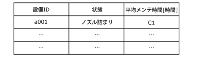
- FIG. 6 is a diagram showing an example of the maintenance time database according to this embodiment.
- the production time database is information in which one or more operating conditions executable by the production apparatus 10 and the time required for production under the operating conditions are associated and managed.
- the production time database includes a first operation pattern, which will be described later.
- the production time is the time required to mount a predetermined number of components on one board. If a nozzle is out of order and the operating condition is a bad nozzle setting that stops using the nozzle, the production time when there is one bad nozzle is B1, and the production time when there are two bad nozzles is B1. B2.
- production time may be lengthened. be. For example, production times B1 and B2 can be longer than production times when no malfunction is detected.
- the production time is associated with each operating condition.
- settable operating conditions at the time of failure and production times under the operating conditions are associated with each other.
- the production time database may include the production time in a normal state when there is no malfunction.
- the production time database may include, as the production time, information indicating the time corresponding to the extension of the production time from the normal operating conditions.
- the maintenance time database includes identifiers (for example, device IDs) that identify respective parts (components) of the production apparatus 10, malfunction states (state information) of the respective parts, and corresponding This information is managed in association with the time required for maintenance to be completed according to the state of each location (in the example of FIG. 6, the average maintenance time (average maintenance time)). For example, a different identifier is set for each of the plurality of nozzles. Also, the average maintenance time may be set for each worker or each worker's level.
- FIG. 6 indicates that when the identifier indicating the nozzle of the production apparatus 10 is "a001" and the malfunction state is "nozzle clogging", the average maintenance time is "C1" hours.
- an average maintenance time C1 is required.
- the average maintenance time "C1" corresponds to, for example, the period between times t2 and t3 shown in FIGS.
- the time required for maintenance is not limited to the average maintenance time, and may be, for example, the maximum maintenance time or other maintenance time.
- the average maintenance time may be set according to the content of maintenance, for example.
- the maintenance time database may include the average maintenance time in each of "replace and continue production (short-term stop)" and “maintenance after production stop (long-term stop)” shown in FIG. 10, which will be described later. .
- the display device 30 has a communication section 31, a control section 32, and a display section 33.
- the communication unit 31 communicates with the production device 10 and the server 20 via the network 40.
- the communication unit 31 includes a communication module (communication circuit).
- the control unit 32 is a control device that controls each component of the production device 10 .
- the control unit 32 performs control for displaying information acquired via the communication unit 31 on the display unit 33, for example.
- the display unit 33 displays an image under the control of the control unit 32.
- the display unit 33 displays, for example, information indicating the recommended timing included in the maintenance information.
- the display unit 33 is implemented by, for example, a display panel.
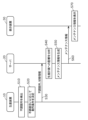
- FIG. 7 is a sequence diagram showing operations of the production control system 1 according to this embodiment.
- the state detection unit 12 of the production device 10 detects a faulty part during production based on the production plan (S10). Further, the state detection unit 12 determines the degree of malfunction at the malfunction location. The state detection unit 12 determines the degree of malfunction based on a table in which the state of malfunction (for example, nozzle clogging) and the degree of malfunction corresponding to the state of malfunction are associated with each other. State detection unit 12 outputs the degree of malfunction to operating condition change unit 13 . It should be noted that the degree of malfunction here is information indicating the degree of malfunction (for example, the degree of failure) of the malfunctioning portion, regardless of the influence on the production plan. The degree of disorder may be a numerical value from 0 to 100, or a rank such as "high", "middle", or "low".
- the operating condition changing unit 13 determines the operating conditions of the production apparatus 10 after the malfunction according to the degree of malfunction acquired from the state detection unit 12 (S20). Then, the control unit 14 controls the production device 10 based on the operating conditions of the production device 10 after the failure determined by the operating condition changing unit 13 . For example, the control unit 14 may continue production under certain operating conditions even after a malfunction.
- the production device 10 outputs information indicating the location of malfunction and status information indicating the state of malfunction to the server 20, and the server 20 acquires the information (S30).
- the information indicating the defective location may be any information that can identify the location (component) of the component mounting apparatus of the production apparatus 10 such as the nozzle, and may be, for example, an ID or a model number.
- the state information may include the state of malfunction (for example, nozzle clogging), and may include the degree of malfunction.
- the production apparatus 10 may transmit to the server 20 information indicating the operating conditions of the production apparatus 10 before failure and the operating conditions after failure determined by the operating condition changing unit 13 in step S20.
- step S30 request information, which will be described later, may be output from the production apparatus 10 to the server 20.
- the server 20 analyzes the impact on the production plan based on the information indicating the malfunctioning part and the status information (S40). For example, as an analysis of the impact on the production plan, as shown in FIGS. 3 and 4, the server 20 analyzes the following: Calculate the degree of impact on the production plan. Then, the server 20 determines the recommended timing for performing maintenance on the production apparatus 10 based on the calculated two or more degrees of influence.
- the server 20 generates maintenance information including the determined recommended timing (S50).
- the maintenance information is information that includes recommended timing that reduces the deviation from the production plan. It can be said that the maintenance information includes information capable of suppressing productivity loss even when a malfunction of the production apparatus 10 is detected.
- the server 20 outputs maintenance information to the display device 30, and the display device 30 acquires the maintenance information (S60).
- the display device 30 displays the obtained maintenance information (S70).
- the control unit 32 controls the maintenance information acquired via the communication unit 31 to be displayed on the display unit 33 .
- the display device 30 can present the operator with the recommended timing for performing maintenance for the malfunction.
- the maintenance information may include, for example, the details of the work performed by the worker.
- the work content includes, for example, replacing parts, cleaning parts, and the like.
- step S30 may be executed, for example, while the production apparatus 10 continues production based on the post-malfunction operating conditions determined by the operating condition changing unit 13 in step S20.
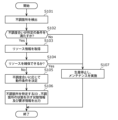
- FIG. 8 is a flow chart showing the operation of the production apparatus 10 according to this embodiment.
- the state detection unit 12 of the production apparatus 10 detects a component (malfunction location) where malfunction has occurred (S101).
- the state detection unit 12 acquires measurement results from, for example, various sensors included in the production apparatus 10 for detecting a malfunction of each component, and detects a malfunction of the component based on the acquired measurement result. To detect.
- the state detection unit 12 detects a malfunction when a predetermined condition is not satisfied, for example, the measurement result is equal to or less than a predetermined threshold value. If the component is a nozzle, for example, if the flow rate is below a predetermined threshold when no component is picked up, or if a component pick-up error occurs, there is a possibility that the nozzle is clogged. Therefore, the state detection unit 12 detects the malfunction of the nozzle.
- Step S101 corresponds to step S10 shown in FIG.
- the timing at which the state detection unit 12 acquires the measurement results from the various sensors is not particularly limited, and may be, for example, at predetermined time intervals or at predetermined production number.
- the degree of malfunction increases, for example, as the flow rate becomes smaller when the component is not being picked up, or as the component pick-up error rate increases.
- the state detection unit 12 determines whether the degree of malfunction of the malfunction location satisfies a predetermined condition (S102).
- the predetermined condition is set in advance for each component or for each type of malfunction, and is stored in the storage unit 26, for example. For example, if the malfunctioning part is a nozzle, whether the flow rate when the component is not picked up is higher than a predetermined threshold value (an example of the first threshold value), or whether the occurrence rate of component pick-up errors is a predetermined threshold value ( example of the first threshold value), it is determined as Yes in step S102.
- a determination of Yes in step S102 means that a malfunction has occurred but the degree of malfunction is low, and a determination of No in step S102 means that a serious malfunction has occurred. means.
- State detection unit 12 outputs the determination result of step S ⁇ b>102 to operating condition change unit 13 . It should be noted that even if the measured production performance of the device is normal, it may be determined whether or not the degree of malfunction satisfies a predetermined condition.
- step S101 does not have to be performed.
- the state detection unit 12 may determine the degree of malfunction of each component of the component mounting apparatus based on the measurement result of the sensor regardless of whether or not the malfunction is detected. Further, in this case, the state detection unit 12 may determine that the component is normal when the degree of malfunction of the component is out of the range for determining that the component is malfunctioning.
- the resource information is information indicating the status of resources required for maintenance of the production apparatus 10 .
- the resource information may be stored in the storage unit 26, may be acquired from the server 20, or may be acquired from another server that manages resource information.
- FIG. 9 is a diagram showing an example of resource information according to this embodiment.
- the resource information includes a replacement resource indicating the inventory of replacement parts and a time (time period) in which maintenance workers can be secured.
- the exchange resource includes, for example, the number of inventories for each part (for example, each of parts A to C).
- the time when a worker can be secured may be obtained from, for example, the worker's work schedule or the like, or may be obtained from the worker in advance.
- the resource information should at least include information about the time (time period) that the maintenance worker can secure.
- the operating condition changing unit 13 determines whether or not resources for maintenance have been secured (S104). For example, when replacement parts are in stock and workers can be secured, the operating condition changing unit 13 determines that resources have been secured.
- the operating condition changing unit 13 determines the operating conditions of the production device 10 according to the degree of malfunction of the malfunctioning location (S105). When the degree of malfunction satisfies a predetermined condition and resources cannot be secured, the operating condition changing unit 13 re-determines the operating conditions according to the degree of malfunction and performs processing for continuing production.
- the operating condition changing unit 13 changes the operating conditions of the malfunctioning portion according to the degree of malfunction, or continues production as a bad setting that cancels the use of the malfunctioning portion, or continues production without changing the operating conditions. Decide whether to continue production (under the same operating conditions).
- the operating condition changing unit 13 determines whether the operating conditions of the production apparatus 10 after the occurrence of the malfunction are changed operating conditions, operating conditions that do not use the malfunctioning part, or the same operating conditions as before the detection of the malfunction. It can be said that either of The operating condition (operating pattern) determined by the operating condition changing unit 13 is an example of a first operating pattern.
- the first operation pattern may include any one of an operation pattern that is the same as before the failure, an operation pattern that changes the operation conditions of the failure location of the production apparatus 10, and an operation pattern that cancels the use of the failure location. I can say
- Changing the operating conditions at the malfunctioning location means changing the operating conditions to those that can reduce the occurrence of malfunctions (for example, component pick-up errors) by, for example, changing (for example, slowing down) the moving speed of the nozzle. do.
- the change of the operating condition may be, for example, changing the operating condition to one that can suppress the occurrence of mistakes, such as changing (for example, increasing) the attracting force.
- Continuing production with a bad setting that cancels the use of the malfunctioning location means, for example, continuing production using one or more nozzles other than the nozzle at the malfunctioning location. Since the number of parts that can be picked up in one pick-up operation decreases, production continues with reduced productivity.
- Continuing production without changing the operating conditions means that pick-up mistakes, etc. occur at a certain frequency, but that mistakes are tolerated and production continues. For example, a part where a component has not been mounted may be recovered by inspection by an operator after production.
- the operating condition changing unit 13 ranks the degree of malfunction according to a threshold value of 2 or more, and performs the determination in step S105 based on a table in which the rank is associated with the changed operating condition, but is not limited to this.
- the operating condition changing unit 13 may make the determination in step S105 by any method as long as it determines the operating conditions for continuing production according to the degree of malfunction.
- the operating condition changing unit 13 may use, for example, the relationship shown in FIG. 10 to determine the operating condition.
- FIG. 10 is a diagram showing the relationship between the failure location and the execution feasibility of countermeasures according to the present embodiment. “O” shown in FIG. 10 indicates that it is executable (or effective if executed), and “ ⁇ ” indicates that it is not executable (or less effective if executed). There is Information indicating the relationship shown in FIG. 10 is set in advance and stored in the storage unit 26, for example.
- step S105 whether or not countermeasures can be executed is associated with each malfunction location.
- the execution feasibility of “operation change” and “bad setting” may be used for determination in step S105.
- the nozzle is indicated as "x" for convenience, but the nozzle may be indicated as "o".
- the beam shown in FIG. 10 means a light source.
- the operation change may be "x".
- the bad setting may be "O".
- the operating conditions and whether or not the bad setting can be executed may be set according to the configuration of the production apparatus 10 .
- the operating condition changing unit 13 may determine which of the possible measures shown in FIG. 10 should be executed according to the degree of malfunction.
- Step S105 corresponds to step S20 shown in FIG.
- the control unit 14 generates an ID (an example of an identifier) that identifies the malfunctioning location, status information indicating the state of the malfunctioning location, and request information requesting calculation of the impact on the production plan, and sends the communication unit 11 to the request information. output to the server 20 via (S106).
- the control unit 14 may include the operating condition determined by the operating condition changing unit 13 in the state information and output it. It may be included in the information and output.
- the status information may include information indicating what operating conditions have been changed, what malfunctions have been detected, and the like. Step S106 corresponds to step S30 shown in FIG.
- the operating condition change unit 13 may be determined to stop and perform maintenance (S107). As a result, maintenance can be performed during production, for example, when the degree of malfunction is too great to continue production even if the operating conditions are changed, or when maintenance can be performed immediately.
- the operating condition changing unit 13 may determine the content of maintenance based on the relationship of whether execution is possible or not shown in FIG. Among the countermeasures shown in FIG. 10, information indicating whether or not to execute "replace and continue production (short-term stop)" and “maintenance after production stop (long-term stop)” may be used in the process of step S107. . "Replace and continue production (short-term stop)” and “maintenance after production stop (long-term stop)” are both included in performing maintenance.
- Replace and continue production refers to replacing defective parts (for example, nozzles) with new nozzles and continuing production. Content.
- Mainntenance due to production stoppage (long-time stoppage) is to continue production after repair, and is a maintenance content that requires a longer maintenance time than when parts are replaced.
- the operating condition changing unit 13 may decide to perform maintenance for the short stop or the long stop when each of the short stop and the long stop is "O". In other words, the operating condition changing unit 13 may determine the maintenance content so as to preferentially perform the maintenance that can be handled with a short-time outage, out of the short-time outage and the long-time outage.
- the operating condition changing unit 13 determines to perform short-time maintenance out of short-term maintenance and long-term maintenance. You may In addition, for example, when the malfunctioning part is a nozzle and there is no inventory of replacement parts based on the resource information, the operating condition changing unit 13 performs maintenance for a long time out of short time stop and long time stop. may be determined.
- step S102 shown in FIG. 8 may be performed by the server 20.
- the state detection unit 12 may output the identifier of the malfunctioning portion and the state information to the server 20 when detecting the malfunctioning portion.
- step S104 may not be performed. That is, if Yes in step S102, the process of step S105 may be executed.
- FIG. 11 is a flowchart (an example of a production control method) showing the operation of server 20 according to this embodiment.
- the processing in FIG. 11 is processing executed by the server 20 that controls the production apparatus 10 .
- the server 20 controls the production apparatus 10 .
- maintenance of the malfunctioning part is performed by stopping production, This is a process for determining the recommended timing of maintenance whether maintenance should be performed after the end of production based on the production plan.
- the control unit 22 of the server 20 determines whether or not request information has been acquired from the production apparatus 10 via the communication unit 21 (S201). If request information has been acquired (Yes in S201), the control unit 22 proceeds to step S202, and if request information has not been acquired (No in S201), returns to step S201 and waits until request information is acquired.
- the control unit 22 acquires the identifier and status information of the malfunction location in accordance with the request information.
- the state information may include the operating condition determined by the operating condition changing unit 13 or information indicating that the operating condition has been changed.
- information indicating whether or not the operation pattern has been changed before and after the occurrence of the malfunction may be obtained in the malfunctioning production apparatus 10 .
- Yes in step S201 corresponds to step S30 shown in FIG. Before and after the occurrence of the malfunction means before and after the state detection unit 12 detects the malfunction.
- control unit 22 determines whether or not the production device 10 has changed the operating conditions (S202). For example, based on the state information, the control unit 22 determines whether or not the operating conditions of the production device 10 have changed before and after the occurrence of the malfunction. The control unit 22 outputs the determination result to the analysis unit 23 .
- the analysis unit 23 analyzes the first degree of impact on the production plan due to the continued change of the operating conditions (S203). It can also be said that the analysis unit 23 analyzes the first degree of impact on the production plan when production is continued under the changed operating conditions and maintenance is performed after the production of the production plan is completed.
- the first degree of influence calculated in step S203 is an example of the fourth degree of influence. In this way, when the operating conditions are changed before and after the occurrence of the malfunction, the fourth degree of influence is identified as the first degree of influence.
- the first degree of influence here corresponds to time D1 shown in FIGS.
- the analysis unit 23 functions as a first identification unit that identifies the first degree of influence.
- step S203 the influence on the production plan is calculated. Details of the processing in step S203 will be described later.
- the analysis unit 23 analyzes the first impact on the production plan by continuing production without changing the operating conditions (S204). . It can also be said that the analysis unit 23 analyzes the first degree of impact on the production plan when production is continued under the operating conditions that have not been changed and maintenance is performed after the production of the production plan is completed.
- the first degree of influence calculated in step S204 is an example of the third degree of influence. In this way, when the operating conditions are not changed before and after the malfunction occurs, the third degree of influence is identified as the first degree of influence.
- the first degree of influence here corresponds to time D1 shown in FIGS.
- the analysis unit 23 functions as a first identification unit that identifies the first degree of influence.
- step S204 the influence on the production plan is calculated. Details of the processing in step S204 will be described later.
- the analysis unit 23 analyzes the second degree of impact on the production plan by suspending production and performing maintenance (S205). It can also be said that the analysis unit 23 calculates the second degree of impact on production when the production of the production apparatus 10 that continues production after the occurrence of the malfunction is stopped and maintenance is performed during production.
- the second degree of influence here corresponds to time D2 shown in FIGS.
- the analysis unit 23 functions as a second identification unit that identifies the second degree of influence.
- the analysis unit 23 outputs the calculated first impact and second impact to the countermeasure determination unit 24 .
- the countermeasure determination unit 24 compares the first degree of impact and the second degree of impact, and determines recommended timing based on the comparison result.
- the countermeasure determination unit 24 determines whether or not the second degree of impact is greater than the first degree of impact (S206).
- the countermeasure determination unit 24 determines whether the time D2 is longer than the time D1.
- the first influence here is, for example, the third influence that is the influence when the operation conditions before and after the occurrence of the malfunction are the same (an example of the first operation pattern and the second operation pattern being the same). and at least one of a fourth influence degree which is the influence degree when the operation conditions before and after the occurrence of the malfunction are different (an example of the difference between the first operation pattern and the second operation pattern).
- the first influence includes one of the third influence and the fourth influence.
- the countermeasure determination unit 24 determines that it is recommended that maintenance be performed after the end of production (S207). If the second degree of impact is large, that is, if performing maintenance during production has a greater impact on the production plan, the countermeasure determination unit 24 determines the continue the production of the production plan, and after the production of the production plan is finished, it is recommended that maintenance be performed.
- the countermeasure determination unit 24 determines that it is recommended to stop production and perform maintenance at a predetermined timing when resources are satisfied (S208). . If the second degree of impact is small, that is, if the impact on the production plan is smaller if maintenance is performed during production, the countermeasure determination unit 24 determines the stop production at a predetermined time to satisfy resources, and recommend that the rest of the production continue after maintenance has been performed. Note that the operating conditions for the rest of the production (for example, the production at times t4 to t9 shown in FIG. 4) may be, for example, the operating conditions before the malfunction occurred.
- the countermeasure determination unit 24 determines the recommended timing for performing maintenance based on the first degree of impact and the second degree of impact. For example, when the first degree of influence is smaller than the second degree of influence, the countermeasure determination unit 24 continues production under the operating conditions (an example of the first operation pattern) after the occurrence of the malfunction and produces a predetermined number of sheets (an example of a predetermined amount). The recommended timing is determined as the timing after the production of is finished. Also, for example, when the first degree of impact is greater than or equal to the second degree of impact, the countermeasure determination unit 24 determines the timing during production as the recommended timing. The recommended timing is, for example, the timing when a malfunction occurs or the timing when resources can be secured. Steps S202 to S208 correspond to step S40 shown in FIG.
- step S206 is made, for example, based on the third degree of influence and the second degree of influence, or based on the fourth degree of influence and the second degree of influence.
- the countermeasure determination unit 24 may determine the predetermined timing based on resource information (see FIG. 9), for example.
- the predetermined timing may be, for example, the time when the worker can perform the work.
- the countermeasure determination unit 24 outputs the determined recommended timing to the information generation unit 25 .
- the information generator 25 generates maintenance information including the determined recommended content (recommended timing) and outputs it to the display device 30 (S209).
- the information generator 25 outputs, for example, maintenance information for displaying recommended content to the display device 30 . Thereby, the worker can be notified of the work timing.
- the information generator 25 may further generate control information for controlling the operation of the production apparatus 10 based on the recommended content (recommended timing) and output it to the production apparatus 10 as maintenance information.
- Step S209 corresponds to steps S50 and S60 shown in FIG.
- step S202 shown in FIG. 11 may not be performed.
- Three influence degrees calculated in steps S203, S204 and S205 may be calculated.
- the countermeasure determination unit 24 may determine, as the recommended timing, the timing for performing maintenance corresponding to the lowest degree of influence among the three degrees of influence.
- step S203 will be described with reference to FIG.
- FIG. 12 is a flow chart showing details of step S203 shown in FIG.
- the analysis unit 23 calculates the first time when production is expected to end under the changed operating conditions (S301).
- step S301 the analysis unit 23 calculates the first time at which the production of the predetermined number of sheets in the production plan is completed when production is continued under the operation condition (an example of the first operation pattern) after the occurrence of the malfunction. Identify a first time.
- the analysis unit 23 identifies the first time by calculating the first time based on the production time database stored in the storage unit 26 and the current time. For example, based on the production time database, the analysis unit 23 calculates the first time required for production when production is continued under the operating conditions after the occurrence of the malfunction, adds the first time to the current time, and obtains the first time. Calculate the time.
- the analysis unit 23 further calculates the first time based on the remaining production quantity in the production plan.
- the first time is the time at which the production of the remaining number of sheets is expected to end in the production plan when the production of the remaining number of sheets is continued under the operating conditions after the occurrence of the malfunction.
- the analysis unit 23 calculates the first time by adding the time obtained by multiplying the remaining production number by the production time according to the operating conditions shown in FIG. 9 to the current time.
- the calculation method is not limited to this.
- the first time corresponds to the time t5 shown in FIG. 3 or the time of the intersection of the solid line of the second countermeasure shown in FIG. 4 and the production quantity p2.
- a production plan for production related to a malfunctioning point means a production plan in a production process (for example, a component mounting process) using a nozzle when the malfunctioning point is a nozzle.
- the production plan is, for example, the production plan indicated by the dashed lines shown in FIG. 3 or 4 .
- the analysis unit 23 calculates the degree of divergence between the scheduled production completion time planned in the production plan and the first time as the first degree of impact (S303). Based on the production plan, the analysis unit 23 identifies the scheduled time at which the production period is scheduled to end (time t3 shown in FIG. 3 or time t8 shown in FIG. 4) as the scheduled production completion time.
- the scheduled time is the time at which production is expected to end if the production apparatus 10 does not malfunction.
- the analysis unit 23 identifies the first impact by calculating the first impact based on the first time and the scheduled time.
- the analysis unit 23 identifies the first degree of impact by comparing the first time and the scheduled time.
- the degree of deviation indicates how much the first time differs from the scheduled production completion time, and in the present embodiment, it indicates how much the first time lags behind the scheduled production completion time.
- the deviation is the time (time D1) between the first time and the scheduled production completion time.
- the analysis unit 23 calculates the time between the first time and the scheduled production completion time, which is the difference between the first time and the scheduled production completion time, as the first influence degree.
- the analysis unit 23 calculates the first degree of impact indicating the impact on the production plan when the production apparatus 10 that has experienced a malfunction during production continues production under changed operating conditions. identified by In this case, the changed operating conditions (operating conditions after the malfunction) are an example of the first operating pattern, and the operating conditions before the malfunction are an example of the second operating pattern.
- step S204 shown in FIG. 11 will be described with reference to FIG.
- FIG. 13 is a flow chart showing details of step S204 shown in FIG.
- the analysis unit 23 calculates the first time when production is expected to end under the operating conditions that have not been changed (S401).
- the analysis unit 23 calculates the first time based on the production time database stored in the storage unit 26 and the remaining production number in the production plan.
- the first time is the estimated time at which the production of the number of products in the production plan is expected to end without performing maintenance during production.
- the analysis unit 23 calculates the first time by adding the time obtained by multiplying the remaining production number by the production time according to the operating conditions shown in FIG. 9 to the current time.
- the calculation method is not limited to this.
- the first time corresponds to the time t5 shown in FIG. 3 or the time of the intersection of the solid line of the second countermeasure shown in FIG. 4 and the production quantity p2. Note that the method of calculating the first time may be the same as in step S301 shown in FIG.
- Step S402 is the same processing as step S302 shown in FIG. 12, and description thereof is omitted.
- the analysis unit 23 determines the degree of deviation between the scheduled production completion time planned in the production plan (time t3 shown in FIG. 3 or time t8 shown in FIG. 4) and the first time as the first impact. Calculate (S403).
- the analysis unit 23 identifies the first degree of influence by comparing the scheduled production completion time and the first time.
- the degree of deviation indicates how much the first time differs from the scheduled production completion time, and in the present embodiment, it indicates how much the first time lags behind the scheduled production completion time.
- the deviation is the time (time D1) between the first time and the scheduled production completion time.
- the analysis unit 23 calculates the time between the first time and the scheduled production completion time, which is the difference between the first time and the scheduled production completion time, as the first influence degree.
- step S204 the analysis unit 23 determines the first degree of impact indicating the impact on the production plan when the production apparatus 10 that has experienced a malfunction during production continues production under unchanged operating conditions. Identify by calculating.
- the unchanged operating conditions are an example of the first operating pattern.
- step S205 shown in FIG. 11 will be described with reference to FIG.
- FIG. 14 is a flow chart showing details of step S205 shown in FIG.
- the analysis unit 23 acquires resource information indicating resources required for maintenance of the production apparatus 10 (S501).
- the resource information may be the same information as the resource information (see FIG. 8) acquired by the production apparatus 10 in step S103.
- the analysis unit 23 calculates (specifies) the time at which maintenance can be started for the malfunctioning location (S502). For example, the analysis unit 23 identifies the time at which the worker can start work as the time at which the maintenance can be started, based on the information about the time slot that the worker who performs maintenance can secure, which is included in the resource information. For example, when the work includes part replacement, the analysis unit 23 may calculate the time at which the replacement resource and the worker can be secured as the time at which maintenance can be started, based on the resource information.
- the analysis unit 23 calculates the average maintenance time for the malfunctioning location (S503).
- the analysis unit 23 calculates an average maintenance time indicating an average time required for maintenance to be completed.
- the analysis unit 23 calculates the average maintenance time of the faulty location based on the maintenance time database stored in the storage unit 26, for example.
- the analysis unit 23 identifies the average maintenance time by calculating the average maintenance time based on the maintenance time database, the identifier for identifying the malfunctioning portion of the production apparatus 10, and the state information of the malfunctioning portion.
- the analysis unit 23 may specify the average maintenance time by multiplying the average maintenance time indicated by the maintenance time database by the number of parts to be replaced.
- the analysis unit 23 may specify the average maintenance time by selecting, for example, the identifier of the malfunctioning location and the average maintenance time corresponding to the malfunctioning location from the maintenance time database.
- the identifier and status information of the malfunctioning portion are obtained from the production apparatus 10 in step S201, for example.
- step S503 may acquire the average maintenance time of the faulty location by referring to the maintenance time database.
- the analysis unit 23 may calculate the average maintenance time based on the diagram of FIG. If the malfunctioning part is a nozzle, head, or feeder, the analysis unit 23 may change the calculated maintenance time according to the presence or absence of replacement resources. If the defective part is a nozzle, head, or feeder and there are replacement resources, that is, if the part can be replaced and production can be continued (short-time stoppage), the analysis unit 23 determines the time required to replace the part. , may be calculated as maintenance time. If the malfunctioning part is a nozzle, head, or feeder and there is no replacement resource, that is, if the malfunctioning part is to be repaired, the analysis unit 23 may calculate the time required to repair the part as the maintenance time. . In addition, when the malfunctioning portion is a transport or beam, the analysis unit 23 may calculate the maintenance time when production is stopped and maintenance is performed, that is, when production is stopped for a long time, as the average maintenance time of the malfunctioning portion. good.
- the analysis unit 23 acquires the production plan and calculates the time required for production (S504).
- the analysis unit 23 calculates the remaining production quantity based on the production plan, and calculates the time required to produce the remaining production quantity under the operating conditions before the occurrence of the malfunction based on the production time database. .
- the analysis unit 23 calculates the time based on the production time database stored in the storage unit 26 and the remaining production number in the production plan. For example, the analysis unit 23 calculates the time obtained by multiplying the remaining production number by the production time according to the operating conditions before the occurrence of the malfunction, but the method of calculating the time is not limited to this.
- the analysis unit 23 calculates a second time at which production is expected to end when maintenance is performed, based on the time when maintenance can start, the average maintenance time, and the time required for production (S505).
- the second time is, for example, the expected completion time of production in the production plan when production is stopped and maintenance is performed at the timing when the malfunction occurs.
- the analysis unit 23 identifies the maintenance completion time indicating the time when the maintenance is expected to be completed based on the resource information, and determines the production time (second time) required until production is completed based on the production plan. The production time is added to the maintenance completion time to calculate the second time.
- the maintenance completion time is information based on resource information.
- the analysis unit 23 can identify the maintenance completion time based on the start time (start time) calculated in step S502 and the average maintenance time (an example of maintenance time) calculated in step S503.
- the analysis unit 23 specifies the maintenance completion time by adding the average maintenance time to the start time.
- the production time is the time it takes after maintenance is completed to resume production under the operating conditions before the malfunction occurred, until the remaining production is completed.
- the analysis unit 23 calculates the production time, for example, based on the production time database and the remaining production number calculated from the production plan.
- the production time may be calculated, for example, by multiplying the production time contained in the production time database by the remaining production number.
- the analysis unit 23 calculates the degree of deviation between the scheduled production completion time planned in the production plan and the second time as a second degree of influence (S506). Based on the production plan, the analysis unit 23 identifies the scheduled time at which the production period is scheduled to end (time t3 shown in FIG. 3 or time t8 shown in FIG. 4) as the scheduled production completion time.
- the scheduled time is the time at which production is expected to end if the production apparatus 10 does not malfunction.
- the analysis unit 23 specifies the second influence by calculating the second influence based on the second time and the scheduled time.
- the degree of deviation indicates how much the second time differs from the scheduled production completion time, and in the present embodiment, it indicates how much the second time lags behind the scheduled production completion time.
- the deviation is the time (time D2) corresponding to the difference between the second time and the scheduled production completion time.
- the analysis unit 23 specifies by calculating the second degree of impact that indicates the impact on the production plan when maintenance of the production device 10 in which the malfunction occurred is performed during production.
- the production management method executed by the server 20 includes a first effect indicating the effect on the production plan when the production apparatus 10, which has experienced a malfunction during production, continues production in the first operation pattern. (S203, S204), and a second degree of influence indicating the influence on the production plan when maintenance of the production apparatus 10 in which the malfunction occurred is performed during production (S205), and the first degree of influence and the degree of influence are identified. Based on the second degree of influence, the recommended timing for performing maintenance is determined (S207, S208), and maintenance information including the determined recommended timing is output (S209).
- the recommended timing for performing maintenance can be determined based on the first degree of impact and the second degree of impact.
- the impact on the production plan is minimized compared to the case where maintenance is uniformly performed after the occurrence of a malfunction (maintenance is performed during production). can be reduced. Therefore, according to the production management method according to the present embodiment, even if the production apparatus 10 malfunctions, the influence on the production plan can be suppressed.
- the degree of impact is the time behind the end time of production in the production plan (for example, time t3 shown in FIG. 3 or time t8 shown in FIG. 4). Not limited to time.
- the impact may be other items that affect production.
- the degree of influence may be the loss amount in production or the yield in production.
- the server may store information indicating the relationship between the location of failure, the status of failure, the amount of loss in production, and the yield in production.
- the first time and the second time may be compared. Then, the earlier of the first time and the second time may be considered to have less deviation from the production plan.
- the present invention is not limited to using the production time database.
- the first time may be calculated using a simulator that calculates the first time from the operating conditions after the occurrence of the malfunction, the production volume, and the like.
- the timing after the end of production in the above embodiment can be said to be the timing at which the production plan is switched.
- the server determines whether to perform maintenance during production or when the production plan changes.
- the first time is the time when the production of the predetermined amount is completed, and the predetermined amount is the remaining production amount based on the production plan.
- the first time may be the time when the production of one workpiece (for example, substrate) is completed.
- the completion of production may be the completion of production of one workpiece (board) or the completion of production of a predetermined number of workpieces (boards) determined in the production plan. .
- the second time in the above embodiment may be the time at which production is completed when production is stopped at the timing when a malfunction occurs in the production apparatus and maintenance is performed immediately. "Immediately" means, for example, starting maintenance before the next workpiece arrives.
- each component may be configured with dedicated hardware or realized by executing a software program suitable for each component.
- Each component may be realized by reading and executing a software program recorded in a recording medium such as a hard disk or a semiconductor memory by a program execution unit such as a CPU or processor.
- each step in the flowchart is executed is for illustrative purposes in order to specifically describe the present disclosure, and orders other than the above may be used. Also, some of the steps may be executed concurrently (in parallel) with other steps, or some of the steps may not be executed.
- the division of functional blocks in the block diagram is an example, and a plurality of functional blocks can be realized as one functional block, one functional block can be divided into a plurality of functional blocks, and some functions can be moved to other functional blocks.
- single hardware or software may process the functions of a plurality of functional blocks having similar functions in parallel or in a time-sharing manner.
- the server according to the above embodiment may be implemented as a single device, or may be implemented by a plurality of devices.
- each component of the server may be distributed to the plurality of devices in any way.
- the communication method between the plurality of devices is not particularly limited, and may be wireless communication or wired communication. Also, wireless and wired communications may be combined between devices.
- each component described in the above embodiments may be realized as software, or typically as an LSI, which is an integrated circuit. These may be made into one chip individually, or may be made into one chip so as to include part or all of them. Although LSI is used here, it may also be called IC, system LSI, super LSI, or ultra LSI depending on the degree of integration. Also, the method of circuit integration is not limited to LSI, and may be realized by a dedicated circuit (for example, a general-purpose circuit that executes a dedicated program) or a general-purpose processor.
- An FPGA Field Programmable Gate Array
- a reconfigurable processor that can reconfigure the connections or settings of the circuit cells inside the LSI may be used. Furthermore, if an integrated circuit technology that replaces the LSI appears due to advances in semiconductor technology or another technology derived from it, the component may naturally be integrated using that technology.
- a system LSI is an ultra-multifunctional LSI manufactured by integrating multiple processing units on a single chip. Specifically, it includes a microprocessor, ROM (Read Only Memory), RAM (Random Access Memory), etc.
- a computer system comprising A computer program is stored in the ROM. The system LSI achieves its functions by the microprocessor operating according to the computer program.
- one aspect of the present disclosure may be a computer program that causes a computer to execute each characteristic step included in the production control method shown in any one of FIGS. 7, 8, and 11 to 14.
- the program may be a program to be executed by a computer.
- one aspect of the present disclosure may be a computer-readable non-transitory recording medium on which such a program is recorded.
- such a program may be recorded on a recording medium and distributed or distributed. For example, by installing the distributed program in a device having another processor and causing the processor to execute the program, it is possible to cause the device to perform the above processes.
- the present disclosure is useful for production management systems and the like for processing objects using production equipment.
Landscapes
- Engineering & Computer Science (AREA)
- Manufacturing & Machinery (AREA)
- General Physics & Mathematics (AREA)
- Physics & Mathematics (AREA)
- Business, Economics & Management (AREA)
- Health & Medical Sciences (AREA)
- Tourism & Hospitality (AREA)
- General Health & Medical Sciences (AREA)
- Human Resources & Organizations (AREA)
- Marketing (AREA)
- Primary Health Care (AREA)
- Strategic Management (AREA)
- Economics (AREA)
- Microelectronics & Electronic Packaging (AREA)
- General Business, Economics & Management (AREA)
- Operations Research (AREA)
- Theoretical Computer Science (AREA)
- General Engineering & Computer Science (AREA)
- Quality & Reliability (AREA)
- Automation & Control Theory (AREA)
- Management, Administration, Business Operations System, And Electronic Commerce (AREA)
Priority Applications (3)
| Application Number | Priority Date | Filing Date | Title |
|---|---|---|---|
| DE112022004307.5T DE112022004307T5 (de) | 2021-09-08 | 2022-06-21 | Produktionsverwaltungsverfahren, Produktionsverwaltungsvorrichtung, und Programm |
| JP2023546782A JPWO2023037693A1 (https=) | 2021-09-08 | 2022-06-21 | |
| CN202280052535.6A CN117730287A (zh) | 2021-09-08 | 2022-06-21 | 生产管理方法、生产管理装置以及程序 |
Applications Claiming Priority (2)
| Application Number | Priority Date | Filing Date | Title |
|---|---|---|---|
| JP2021146484 | 2021-09-08 | ||
| JP2021-146484 | 2021-09-08 |
Publications (1)
| Publication Number | Publication Date |
|---|---|
| WO2023037693A1 true WO2023037693A1 (ja) | 2023-03-16 |
Family
ID=85506282
Family Applications (1)
| Application Number | Title | Priority Date | Filing Date |
|---|---|---|---|
| PCT/JP2022/024702 Ceased WO2023037693A1 (ja) | 2021-09-08 | 2022-06-21 | 生産管理方法、生産管理装置及びプログラム |
Country Status (4)
| Country | Link |
|---|---|
| JP (1) | JPWO2023037693A1 (https=) |
| CN (1) | CN117730287A (https=) |
| DE (1) | DE112022004307T5 (https=) |
| WO (1) | WO2023037693A1 (https=) |
Cited By (2)
| Publication number | Priority date | Publication date | Assignee | Title |
|---|---|---|---|---|
| WO2025004416A1 (ja) * | 2023-06-27 | 2025-01-02 | パナソニックIpマネジメント株式会社 | メンテナンス計画作成方法、メンテナンス計画作成装置、プログラム、および、メンテナンス方法 |
| WO2025163933A1 (ja) * | 2024-01-30 | 2025-08-07 | パナソニックIpマネジメント株式会社 | 部品実装システム、管理装置および情報処理方法 |
Citations (5)
| Publication number | Priority date | Publication date | Assignee | Title |
|---|---|---|---|---|
| JP2005202685A (ja) * | 2004-01-15 | 2005-07-28 | Hitachi Ltd | 保守計画の評価方法及び保守計画の評価装置 |
| JP2008112209A (ja) * | 2006-10-27 | 2008-05-15 | Omron Corp | 稼働状態モニタリング装置、稼働状態モニタリング方法、およびプログラム |
| WO2011152108A1 (ja) * | 2010-05-31 | 2011-12-08 | 東京電力株式会社 | 復水器の性能管理方法、発電プラントの管理方法、管理システム、及びプログラム |
| WO2018079778A1 (ja) * | 2016-10-31 | 2018-05-03 | 日本電気株式会社 | 生産管理装置、方法、プログラム |
| JP2020069596A (ja) * | 2018-10-31 | 2020-05-07 | 株式会社三井ハイテック | 加工装置及び加工方法 |
-
2022
- 2022-06-21 WO PCT/JP2022/024702 patent/WO2023037693A1/ja not_active Ceased
- 2022-06-21 DE DE112022004307.5T patent/DE112022004307T5/de active Pending
- 2022-06-21 JP JP2023546782A patent/JPWO2023037693A1/ja active Pending
- 2022-06-21 CN CN202280052535.6A patent/CN117730287A/zh active Pending
Patent Citations (5)
| Publication number | Priority date | Publication date | Assignee | Title |
|---|---|---|---|---|
| JP2005202685A (ja) * | 2004-01-15 | 2005-07-28 | Hitachi Ltd | 保守計画の評価方法及び保守計画の評価装置 |
| JP2008112209A (ja) * | 2006-10-27 | 2008-05-15 | Omron Corp | 稼働状態モニタリング装置、稼働状態モニタリング方法、およびプログラム |
| WO2011152108A1 (ja) * | 2010-05-31 | 2011-12-08 | 東京電力株式会社 | 復水器の性能管理方法、発電プラントの管理方法、管理システム、及びプログラム |
| WO2018079778A1 (ja) * | 2016-10-31 | 2018-05-03 | 日本電気株式会社 | 生産管理装置、方法、プログラム |
| JP2020069596A (ja) * | 2018-10-31 | 2020-05-07 | 株式会社三井ハイテック | 加工装置及び加工方法 |
Cited By (2)
| Publication number | Priority date | Publication date | Assignee | Title |
|---|---|---|---|---|
| WO2025004416A1 (ja) * | 2023-06-27 | 2025-01-02 | パナソニックIpマネジメント株式会社 | メンテナンス計画作成方法、メンテナンス計画作成装置、プログラム、および、メンテナンス方法 |
| WO2025163933A1 (ja) * | 2024-01-30 | 2025-08-07 | パナソニックIpマネジメント株式会社 | 部品実装システム、管理装置および情報処理方法 |
Also Published As
| Publication number | Publication date |
|---|---|
| JPWO2023037693A1 (https=) | 2023-03-16 |
| DE112022004307T5 (de) | 2024-07-18 |
| CN117730287A (zh) | 2024-03-19 |
Similar Documents
| Publication | Publication Date | Title |
|---|---|---|
| JP4736733B2 (ja) | 生産管理装置、生産管理システム、生産管理方法、制御プログラム、および記録媒体 | |
| US20170023931A1 (en) | Data updating method of circuit board work system and circuit board work system | |
| US7818086B2 (en) | Component mounter, warning notification apparatus, and warning notification method | |
| CN104684270A (zh) | 用于监视和预测smt设备的故障的系统及其操作方法 | |
| US7409258B2 (en) | Method and system for measuring customer delivery service | |
| WO2023037693A1 (ja) | 生産管理方法、生産管理装置及びプログラム | |
| US11131984B2 (en) | Substrate production control system and substrate production control method | |
| US10058020B2 (en) | Electronic component mounting system | |
| CN104684271A (zh) | 用于监视和预测smt设备的故障的系统及其操作方法 | |
| US10466685B2 (en) | Production management method of substrate in component mounting system | |
| US11550293B2 (en) | Board production management device and board production management method to determine a countermeasure to a board production device error | |
| US11829917B2 (en) | Standby position determination device and standby position determination method | |
| WO2014061072A1 (ja) | テープフィーダ部品照合システム | |
| KR101889739B1 (ko) | Smt 생산라인 설비 이상 진단 시스템의 최적 배치 시스템 및 방법 | |
| US10891575B2 (en) | Facility configuration creation support system and facility configuration creation support method | |
| JP6792393B2 (ja) | 部品実装ラインの地震発生時緊急停止システム | |
| WO2024065779A1 (en) | Method for manufacturing operation management, edge device, cloud device, and storage medium | |
| JP7478958B2 (ja) | 部品実装システム、部品実装方法、管理装置、およびプログラム | |
| EP3588423B1 (en) | Failure information sharing system | |
| US20190313559A1 (en) | Production plan creation system and production plan creation method | |
| WO2022158227A1 (ja) | 生産フロア管理システム、作業効果判定方法および作業効果判定プログラム | |
| JP2025138359A (ja) | 管理装置、管理方法、および、プログラム | |
| JP7576748B2 (ja) | 保守作業通知システム及び保守作業通知方法 | |
| JP2013214196A (ja) | 電子機器試験装置 | |
| JP2025139719A (ja) | 管理装置、管理方法、および、プログラム |
Legal Events
| Date | Code | Title | Description |
|---|---|---|---|
| 121 | Ep: the epo has been informed by wipo that ep was designated in this application |
Ref document number: 22867020 Country of ref document: EP Kind code of ref document: A1 |
|
| WWE | Wipo information: entry into national phase |
Ref document number: 2023546782 Country of ref document: JP |
|
| WWE | Wipo information: entry into national phase |
Ref document number: 202280052535.6 Country of ref document: CN |
|
| WWE | Wipo information: entry into national phase |
Ref document number: 112022004307 Country of ref document: DE |
|
| 122 | Ep: pct application non-entry in european phase |
Ref document number: 22867020 Country of ref document: EP Kind code of ref document: A1 |