WO2023037579A1 - インバータ制御装置、電動パワーステアリングシステム、電動車両システム - Google Patents
インバータ制御装置、電動パワーステアリングシステム、電動車両システム Download PDFInfo
- Publication number
- WO2023037579A1 WO2023037579A1 PCT/JP2022/005924 JP2022005924W WO2023037579A1 WO 2023037579 A1 WO2023037579 A1 WO 2023037579A1 JP 2022005924 W JP2022005924 W JP 2022005924W WO 2023037579 A1 WO2023037579 A1 WO 2023037579A1
- Authority
- WO
- WIPO (PCT)
- Prior art keywords
- inverter
- pwm pulse
- pwm
- pulse signal
- control device
- Prior art date
- Legal status (The legal status is an assumption and is not a legal conclusion. Google has not performed a legal analysis and makes no representation as to the accuracy of the status listed.)
- Ceased
Links
Images

Classifications
-
- H—ELECTRICITY
- H02—GENERATION; CONVERSION OR DISTRIBUTION OF ELECTRIC POWER
- H02M—APPARATUS FOR CONVERSION BETWEEN AC AND AC, BETWEEN AC AND DC, OR BETWEEN DC AND DC, AND FOR USE WITH MAINS OR SIMILAR POWER SUPPLY SYSTEMS; CONVERSION OF DC OR AC INPUT POWER INTO SURGE OUTPUT POWER; CONTROL OR REGULATION THEREOF
- H02M7/00—Conversion of AC power input into DC power output; Conversion of DC power input into AC power output
- H02M7/42—Conversion of DC power input into AC power output without possibility of reversal
- H02M7/44—Conversion of DC power input into AC power output without possibility of reversal by static converters
- H02M7/48—Conversion of DC power input into AC power output without possibility of reversal by static converters using discharge tubes with control electrode or semiconductor devices with control electrode
- H02M7/53—Conversion of DC power input into AC power output without possibility of reversal by static converters using discharge tubes with control electrode or semiconductor devices with control electrode using devices of a triode or transistor type requiring continuous application of a control signal
- H02M7/537—Conversion of DC power input into AC power output without possibility of reversal by static converters using discharge tubes with control electrode or semiconductor devices with control electrode using devices of a triode or transistor type requiring continuous application of a control signal using semiconductor devices only, e.g. single switched pulse inverters
- H02M7/539—Conversion of DC power input into AC power output without possibility of reversal by static converters using discharge tubes with control electrode or semiconductor devices with control electrode using devices of a triode or transistor type requiring continuous application of a control signal using semiconductor devices only, e.g. single switched pulse inverters with automatic control of output wave form or frequency
- H02M7/5395—Conversion of DC power input into AC power output without possibility of reversal by static converters using discharge tubes with control electrode or semiconductor devices with control electrode using devices of a triode or transistor type requiring continuous application of a control signal using semiconductor devices only, e.g. single switched pulse inverters with automatic control of output wave form or frequency by pulse-width modulation
-
- H—ELECTRICITY
- H02—GENERATION; CONVERSION OR DISTRIBUTION OF ELECTRIC POWER
- H02P—CONTROL OR REGULATION OF ELECTRIC MOTORS, ELECTRIC GENERATORS OR DYNAMO-ELECTRIC CONVERTERS; CONTROLLING TRANSFORMERS, REACTORS OR CHOKE COILS
- H02P27/00—Arrangements or methods for the control of AC motors characterised by the kind of supply voltage
- H02P27/04—Arrangements or methods for the control of AC motors characterised by the kind of supply voltage using variable-frequency supply voltage, e.g. inverter or converter supply voltage
- H02P27/06—Arrangements or methods for the control of AC motors characterised by the kind of supply voltage using variable-frequency supply voltage, e.g. inverter or converter supply voltage using DC to AC converters or inverters
- H02P27/08—Arrangements or methods for the control of AC motors characterised by the kind of supply voltage using variable-frequency supply voltage, e.g. inverter or converter supply voltage using DC to AC converters or inverters with pulse width modulation
-
- B—PERFORMING OPERATIONS; TRANSPORTING
- B60—VEHICLES IN GENERAL
- B60L—PROPULSION OF ELECTRICALLY-PROPELLED VEHICLES; SUPPLYING ELECTRIC POWER FOR AUXILIARY EQUIPMENT OF ELECTRICALLY-PROPELLED VEHICLES; ELECTRODYNAMIC BRAKE SYSTEMS FOR VEHICLES IN GENERAL; MAGNETIC SUSPENSION OR LEVITATION FOR VEHICLES; MONITORING OPERATING VARIABLES OF ELECTRICALLY-PROPELLED VEHICLES; ELECTRIC SAFETY DEVICES FOR ELECTRICALLY-PROPELLED VEHICLES
- B60L15/00—Methods, circuits, or devices for controlling the traction-motor speed of electrically-propelled vehicles
- B60L15/007—Physical arrangements or structures of drive train converters specially adapted for the propulsion motors of electric vehicles
-
- B—PERFORMING OPERATIONS; TRANSPORTING
- B62—LAND VEHICLES FOR TRAVELLING OTHERWISE THAN ON RAILS
- B62D—MOTOR VEHICLES; TRAILERS
- B62D5/00—Power-assisted or power-driven steering
- B62D5/04—Power-assisted or power-driven steering electrical, e.g. using an electric servo-motor connected to, or forming part of, the steering gear
- B62D5/0457—Power-assisted or power-driven steering electrical, e.g. using an electric servo-motor connected to, or forming part of, the steering gear characterised by control features of the drive means as such
- B62D5/046—Controlling the motor
Definitions
- the present invention relates to an inverter control device, an electric power steering system and an electric vehicle system using the same.
- Inverter control devices that control the driving of inverters by PWM (Pulse Width Modulation) control to drive motors are widely used.
- PWM Pulse Width Modulation
- the output voltage command of the inverter is operated in an overmodulation mode (overmodulation region) in which the maximum output level (sine wave) of the inverter is exceeded, and the output voltage is further increased. Therefore, there is known a technique of operating in a one-pulse mode (one-pulse region) in which PWM pulse trains are connected to form one pulse.
- Patent Document 1 The technique of Patent Document 1 is known for reducing the current ripple in the overmodulation region.
- Patent Document 1 when performing trapezoidal wave modulation using a trapezoidal wave in an overmodulation region, the areas of on-pulses and off-pulses of a plurality of PWM pulses in an inversion region of a modulated wave that changes from the base to the top of the trapezoidal wave are measured.
- An inverter device is described that generates PWM pulses such that the integrated values are equal.
- Patent Document 1 With the technique of Patent Document 1, it is not possible to appropriately control the periodicity of the pulse train that repeats the positive and negative (180 degree) cycles of the modulated wave in the operating state of the motor in which the number of PWM pulses is small. Therefore, an error occurs in the output voltage of the inverter, and there is a possibility that the DC component and the low-order harmonic component increase in the output current of the inverter.
- An inverter control device includes a PWM pulse generator that generates a PWM pulse signal for controlling an inverter at each predetermined control cycle, and the PWM pulse generator generates a PWM pulse signal that is asynchronous with the control cycle. While generating, at least three or more pulses exist in one cycle of the fundamental wave of the output voltage of the inverter, and the PWM pulse signal is turned on/off at zero cross points where the fundamental wave changes across 0. The PWM pulse signal is generated so as to satisfy the pulse generation condition that the state is switched.
- An electric power steering system includes an inverter control device, the inverter controlled by the inverter control device, and an AC motor driven by the inverter, and controls steering of a vehicle using the AC motor. do.
- An electric vehicle system includes an inverter control device, the inverter controlled by the inverter control device, and an AC motor driven by the inverter, and runs using the driving force of the AC motor.
- the present invention it is possible to reduce the DC component and low-order harmonic component of the inverter output current generated in the operating state of the motor in which the number of PWM pulses is small.
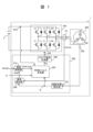
- FIG. 1 is a block diagram showing the configuration of a motor device having an inverter control device according to a first embodiment of the present invention
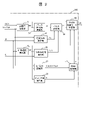
- FIG. FIG. 2 is a block diagram showing the functional configuration of a PWM pulse generator according to the first embodiment of the present invention
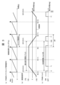
- FIG. FIG. 4 is an explanatory diagram of a method of generating an asynchronous pulse signal according to the first embodiment of the present invention; The figure which showed the asynchronous pulse signal about the range for 1 period of the modulated wave signal. 4 is a flowchart of PWM pulse control according to the first embodiment of the present invention
- FIG. 2 is a block diagram showing the functional configuration of a PWM pulse generator according to the first embodiment of the present invention
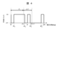
- FIG. 9 is an explanatory diagram of a method of generating an asynchronous pulse signal according to the second embodiment of the present invention. The figure which showed the asynchronous pulse signal about the range for 1 period of the modulated wave signal.
- 6 is a flowchart of PWM pulse control according to the second embodiment of the present invention; 1 is a configuration diagram of an electric power steering device to which an inverter control device is applied; FIG. 1 is a configuration diagram of an electric vehicle to which an inverter control device is applied; FIG.
- the present invention is an inverter control device that controls an inverter by PWM control.
- PWM pulse control according to the modulation method (sine wave modulation, two-phase modulation, trapezoidal wave modulation, etc.)
- the edge of the PWM pulse is generated at the timing corresponding to the zero crossing of the modulated wave, and the 180-degree cycle of the modulated wave is generated.
- the DC component and low-order harmonic component of the output current of the inverter are reduced, and the output of the inverter is increased. be.
- FIG. 1 is a block diagram showing the configuration of a motor device 1 having an inverter control device 200 according to the first embodiment of the invention.
- Motor device 1 is connected to battery 2 and has inverter 100 , inverter control device 200 and motor 300 .
- the battery 2 is a DC voltage source for the inverter 100 .
- the DC voltage DCV of the battery 2 is converted by the inverter 100 into a three-phase AC voltage of variable voltage and variable frequency, and applied to the motor 300 .
- the motor 300 is a synchronous motor that is rotationally driven by the supply of a three-phase AC voltage.
- a rotational position sensor 320 is attached to the motor 300 in order to control the phase of the three-phase AC voltage applied to the motor 300 from the inverter 100 so as to match the phase of the induced voltage of the motor 300 .
- the rotational position sensor 320 for example, a resolver composed of an iron core and windings can be used.
- the rotational position sensor 320 may be configured using a GMR sensor or Hall element.
- the inverter control device 200 has a current control section 210 , a PWM pulse generation section 250 , a drive signal generation section 260 , a rotational position detection section 270 and a current detection section 280 .
- the rotational position detector 270 detects the rotational position ⁇ of the rotor of the motor 300 based on the output signal of the rotational position sensor 320 .
- the current detection unit 280 acquires three-phase current detection values (Iu, Iv, Iw) flowing through the motor 300 from the current sensor Ict, and detects these currents based on the rotational position ⁇ detected by the rotational position detection unit 270.
- dq-axis current detection values (Id, Iq) are obtained by converting the values into 3-phase/2-phase.
- the inverter control device 200 has a current control function for controlling the output of the motor 300.
- the current control unit 210 adjusts the current detection values (Id, Iq) detected by the current detection unit 280 so that the current command values (Id*, Iq*) input from a host controller (not shown) match. , to output voltage commands (Vd*, Vq*).
- PWM pulse generation unit 250 generates voltage commands (Vd*, Vq*) obtained by current control unit 210, DC voltage DCV of battery 2, rotational position ⁇ , and predetermined carrier frequency fc. is used to perform three-phase pulse width modulation (PWM) to generate a PWM pulse signal Pr for controlling the inverter 100 .
- PWM pulse width modulation
- the drive signal generator 260 converts the PWM pulse signal Pr generated by the PWM pulse generator 250 into a drive signal DR and outputs the drive signal DR to the inverter 100 .
- Inverter 100 has a plurality of semiconductor switch elements corresponding to each phase of the three-phase AC voltage, and each semiconductor switch element is on/off controlled by drive signal DR. Thereby, the output voltage of inverter 100 is adjusted according to the control of inverter control device 200 .
- FIG. 2 is a block diagram showing the functional configuration of the PWM pulse generator 250 according to the first embodiment of the invention.
- the PWM pulse generation unit 250 includes a modulation factor calculation unit 51, a rotation speed calculation unit 52, a pulse phase angle calculation unit 53, a voltage phase calculation unit 54, a phase change width calculation unit 55, and a pulse setting unit. 56 , a dq/three-phase converter 57 , a carrier wave calculator 58 , a PWM controller 59 and a PWM control mode determiner 60 .
- Inverter control device 200 including PWM pulse generator 250 is configured by, for example, a microcomputer, and these functional blocks can be realized by executing a predetermined program in the microcomputer. Alternatively, some or all of these functional blocks may be implemented using hardware circuits such as logic ICs and FPGAs.
- Modulation factor calculation unit 51 calculates a modulation factor MF of the output voltage of inverter 100 using the following equation (1) based on DC voltage DCV of battery 2 and voltage commands (Vd*, Vq*).
- Modulation factor MF represents the voltage amplitude ratio between the DC power supplied from battery 2 to inverter 100 and the AC power output from inverter 100 to motor 300 .
- the rotation speed calculator 52 calculates a motor rotation speed ⁇ r representing the rotation speed (number of rotations) of the motor 300 from the time change of the rotation position ⁇ .
- the motor rotation speed ⁇ r may be a value represented by either angular velocity (rad/s) or rotation speed (rpm). Also, these values may be converted to each other and used.
- the pulse phase angle calculator 53 calculates a pulse phase angle ⁇ for switching the ON/OFF state of the PWM pulse signal Pr based on the modulation factor MF calculated by the modulation factor calculator 51 .
- a plurality of pulse phase angles ⁇ are calculated according to the number of pulses N of the PWM pulse signal Pr included in one period of the fundamental wave of the output voltage of the inverter 100 .
- the pulse phase angles ⁇ 1, ⁇ 2, ⁇ 1′ and ⁇ 2′ represented by the following equations (2) to (5) are calculated.
- each pulse width of the PWM pulse signal Pr can be set based on the modulation factor MF.
- ⁇ 1 arccos ⁇ (1+MF)/2 ⁇
- ⁇ 2 ⁇ 1
- ⁇ 1′ ⁇ + ⁇ 1 (4)
- ⁇ 2′ 2 ⁇ 1 (5)
- the number of pulses N can be set, for example, to an odd number of at least 3 or more, and is preset in the inverter control device 200 . Alternatively, it may be arbitrarily set by the user, or arbitrarily switched according to the operating state of the motor 300 or the like.
- the number of pulse phase angles ⁇ calculated by the pulse phase angle calculator 53 is determined according to the number N of pulses, and the larger the number N of pulses, the larger the number of pulse phase angles ⁇ . In this embodiment, the case where the number of pulses N is 3 will be described.
- the voltage phase calculation unit 54 calculates the voltage output from the inverter 100 in response to the current command values (Id*, Iq*) input from the host controller.
- a voltage phase ⁇ v corresponding to the phase angle of is calculated.
- Phase change width calculation unit 55 calculates a phase change width ⁇ of the output voltage of inverter 100 in the control cycle of inverter control device 200 .
- the control cycle of the inverter control device 200 represents the cycle in which the PWM pulse generation unit 250 generates the PWM pulse signal Pr. It is set in advance according to the accuracy required for control.
- the pulse setting unit 56 determines the timing of each pulse edge present within the current control cycle. set. Then, the asynchronous pulse signal P is generated by changing the signal voltage from on to off or from off to on according to the set timing of each pulse edge. Details of the asynchronous pulse signal P generated by the pulse setting section 56 will be described later.
- the dq/three-phase converter 57 performs three-phase conversion on the voltage commands (Vd*, Vq*) based on the rotational position ⁇ , and converts the three-phase voltage commands Vu*, Vv*, Vw* (U-phase voltage command values Vu*, V-phase voltage command value Vv*, and W-phase voltage command value Vw*) are calculated. Thereby, the three-phase voltage commands Vu*, Vv*, Vw* can be generated as modulated wave signals for the three-phase AC voltage. At this time, by selecting a modulation method other than sine wave modulation, the three-phase voltage commands Vu*, Vv* and Vw* may be generated.
- the carrier wave calculator 58 determines a synchronous carrier frequency fcs synchronized with the rotation of the motor 300 based on the motor rotation speed ⁇ r, and generates a carrier wave Tr that periodically changes at this synchronous carrier frequency fcs.
- the carrier wave Tr may be either a triangular wave or a sawtooth wave. If the carrier frequency fcs is 15 times or more the rotation frequency of the motor 300, the carrier frequency fcs does not have to be synchronized with the rotation of the motor 300.
- the PWM control unit 59 uses the carrier wave Tr output from the carrier wave calculation unit 58 to pulse width modulate the three-phase voltage commands Vu*, Vv*, Vw* output from the dq/three-phase conversion unit 57. to generate a synchronous pulse signal P' synchronized with the control period (carrier wave Tr).
- a synchronizing pulse signal P' it will simply be referred to as a synchronizing pulse signal P'.
- a PWM control mode determination unit 60 determines which of the asynchronous pulse signal P generated by the pulse setting unit 56 and the synchronous pulse signal P' generated by the PWM control unit 59 is based on the modulation factor MF and the motor rotation speed ⁇ r. to choose. Then, the selected asynchronous pulse signal P or synchronous pulse signal P′ is output to the drive signal generator 260 as the PWM pulse signal Pr by the PWM pulse generator 250 .
- the PWM control mode determination unit 60 selects a synchronization mode in which a pulse signal is synchronized with the control cycle, and selects a synchronization pulse signal.
- the signal P' is output as the PWM pulse signal Pr.
- the asynchronous mode is selected to generate a pulse signal asynchronous with respect to the control cycle, and the asynchronous pulse signal P is output as the PWM pulse signal Pr.
- the PWM control mode determination unit 60 selectively outputs either the asynchronous pulse signal P or the synchronous pulse signal P' as the PWM pulse signal Pr based on the operating state of the motor 300. Note that regardless of whether the synchronous mode or the asynchronous mode is selected, it is possible to use an arbitrary modulation method among modulation methods such as sinusoidal wave modulation, two-phase modulation, and trapezoidal wave modulation.
- a synchronous pulse signal P' is generated as a PWM pulse signal Pr based on a comparison result between the carrier wave Tr and the modulated wave signal.
- the asynchronous pulse signal P generated as the PWM pulse signal Pr by the pulse setting unit 56 is directly generated from the result of the calculation performed in the PWM pulse generation unit 250 without using the carrier wave Tr or the modulated wave signal. be done. Specifically, pulse phase angle ⁇ , the voltage phase ⁇ v and the phase change width ⁇ are obtained, and the pulse setting unit 56 sets the timing of each pulse edge for each control cycle using these calculation results.
- a signal P is generated.
- it will simply be referred to as an asynchronous pulse signal P.
- FIG. 3 is an explanatory diagram of the method of generating the asynchronous pulse signal P according to the first embodiment of the present invention.
- the graph shown in (a) represents the counter value of the PWM timer
- the graph shown in (b) represents the modulated wave signal
- the graph shown in (c) represents the PWM pulse train output as the asynchronous pulse signal P. shows an example.
- the counter value of the PWM timer shown in FIG. 3A corresponds to the carrier wave Tr generated by the carrier wave calculator 58.
- FIG. 3 the counter value of the PWM timer shown in FIG. 3A corresponds to the carrier wave Tr generated by the carrier wave calculator 58.
- the pulse setting unit 56 generates an asynchronous pulse signal P using a PWM timer whose counter value periodically increases and decreases at a constant carrier period Tc, as shown in FIG. 3(a), for example.
- a PWM timer whose counter value periodically increases and decreases at a constant carrier period Tc, as shown in FIG. 3(a), for example.
- the timing of the control processing related to the generation of the asynchronous pulse signal P is made asynchronous with the control cycle while synchronizing with the rotation of the motor 300. be able to.
- the counter value increases from 0 to the maximum value MaxCount at a constant rate, and the counter value is reset to 0 every carrier cycle Tc according to the timing of the control processing.
- any other type of PWM timer may be used as long as the value periodically increases or decreases at a constant carrier period Tc.
- Tc constant carrier period
- the inverter controller 200 synchronizes with the carrier period Tc shown in FIG. control processing is performed. Specifically, the current detection unit 280 samples and holds the detection signal of the current sensor Ict at a timing synchronized with the carrier cycle Tc, and acquires current detection values (Iu, Iv, Iw). Further, the rotational position detector 270 detects the output signal of the rotational position sensor 320 at a timing synchronized with the carrier period Tc to obtain the rotational position ⁇ . Then, using these acquired values, the asynchronous pulse signal P is generated by executing the above-described calculation every carrier cycle Tc.
- a voltage ripple occurs when the detection signal is charged to the capacitor of the sampling and holding circuit, and this voltage ripple is generated by the A/D conversion circuit.
- A/D conversion noise may be generated by superimposing on the input terminal of .
- the cycle of this A/D conversion noise is equivalent to the control cycle (carrier cycle Tc) of inverter control device 200 . It is also possible to make the detection cycle of the current detection unit 280 shorter than the control cycle and acquire the detection signal from the current sensor Ict a plurality of times per one control cycle.
- the frequency (reciprocal of the detection cycle) must be an integer multiple of the control frequency (reciprocal of the control cycle) of inverter control device 200 .
- an integer multiple of the period of the A/D conversion noise can be regarded as the carrier period Tc, which is the period of the PWM timer.
- FIG. 3(b) shows an example of a modulated wave signal in the case of trapezoidal wave modulation.
- the period of this modulated wave corresponds to the fundamental wave period of the output voltage of inverter 100 .
- the asynchronous pulse signal P is obtained directly by calculation. Therefore, the modulated wave signal is not necessarily required when the asynchronous pulse signal P is generated.
- the asynchronous pulse signal P in this embodiment has zero crossing points (phase angles 0°, 180°) where the modulated wave crosses 0 and reverses from negative to positive, or from positive to negative, and phase angles ⁇ 1, ⁇ 2, ⁇ 1 ', ⁇ 2', the ON/OFF states of the signals are switched respectively.
- the phase angles ⁇ 1, ⁇ 2, ⁇ 1', and ⁇ 2' are obtained by the above-described formulas (2) to (5), respectively.
- the pulse setting unit 56 sets the zero-cross point of the modulated wave shown in FIG. , the asynchronous pulse signal P shown in FIG. 3(c) is generated. Specifically, for example, when the current control processing timing is the control processing timing Tt(i) in FIG.
- the asynchronous pulse signal P is generated in the range (phase change width ⁇ ) up to the voltage phase ⁇ (i+1) corresponding to the control processing timing of .
- the phase angles ⁇ 2, ⁇ 1′ and the zero-crossing point phase angle 180°
- the timer values corresponding to these phase angles are set in the PWM timers respectively.
- the signal value of the asynchronous pulse signal P is changed from ON to OFF or from OFF to ON, thereby setting a pulse edge and generating an asynchronous pulse.
- a signal P can be generated.
- the voltage phase calculator 54 calculates the voltage phase ⁇ v corresponding to the voltage phase ⁇ (i) at the current control processing timing. Further, the phase change width calculator 55 calculates the phase change width ⁇ from the voltage phase ⁇ (i) at the current control processing timing to the voltage phase ⁇ (i+1) at the next control processing timing. Based on these calculated values ⁇ v and ⁇ , the pulse setting unit 56 sets the timer value corresponding to the pulse edge in the current control process to the PWM timer, thereby calculating the pulse phase angle calculated by the pulse phase angle calculation unit 53.
- An asynchronous pulse signal P can be generated according to the pulse phase angle ⁇ .
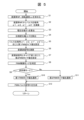
- FIG. 5 is a flowchart of PWM pulse control according to the first embodiment of the present invention.
- the PWM pulse generator 250 performs PWM pulse control by executing the process shown in the flowchart of FIG. Output to the signal generator 260 .
- step S1 the PWM pulse generator 250 obtains the modulation factor MF and the motor rotation speed ⁇ r using the modulation factor calculation part 51 and the rotation speed calculation part 52, respectively.
- the modulation factor MF and the motor rotation speed ⁇ r can be calculated using the above-described equations (1) and (2), respectively.
- step S2 the PWM pulse generator 250 uses the pulse phase angle calculator 53 to calculate the pulse phase angle ⁇ based on the modulation factor MF obtained in step S1.
- the number of ON/OFF switching times of the asynchronous pulse signal P per cycle of the fundamental wave of the inverter output voltage is determined according to the preset number of pulses N, and the fundamental wave of the inverter output voltage is determined from the number of switching times.
- step S2 is performed by calculating the four pulse phase angles ⁇ 1, ⁇ 2, ⁇ 1', and ⁇ 2' using the above equations (2) to (5).
- step S3 the PWM pulse generator 250 uses the voltage phase calculator 54 to calculate the voltage phase ⁇ v.
- the phase angle of the inverter output voltage is calculated using the above equation (6).
- a voltage phase ⁇ v corresponding to is calculated.
- step S4 the PWM pulse generator 250 uses the phase change width calculator 55 to calculate the phase change width ⁇ .
- the above-described formula (7) is used to determine the output of the PWM pulse generator 250.
- a phase change width ⁇ of the inverter output voltage in the control cycle is calculated.
- step S5 the PWM pulse generation unit 250 causes the pulse setting unit 56 to set timer values (first PWM timer values) corresponding to the pulse phase angles ⁇ 1, ⁇ 2, ⁇ 1′, and ⁇ 2′ obtained in step S2 to the PWM timer. do.
- timer values first PWM timer values
- the basic value of the inverter output voltage included in the period from the current control processing timing to the next control processing timing is calculated. Identify the voltage phase range of the wave.
- the ON/OFF switching timing of the PWM pulse signal Pr can be set based on the pulse phase angle ⁇ , voltage phase ⁇ v, and phase change width ⁇ obtained in steps S2 to S4.
- step S6 the PWM pulse generation unit 250 uses the dq/three-phase conversion unit 57 to calculate a modulated wave signal for the three-phase AC voltage.
- the voltage commands (Vd*, Vq*) input from the current control unit 210 are subjected to three-phase conversion based on the rotational position ⁇ , resulting in a three-phase voltage corresponding to the modulated wave signal.
- Commands Vu*, Vv*, Vw* can be generated.
- step S7 the PWM pulse generation unit 250 causes the PWM control unit 59 to perform pulse width modulation based on the modulated wave signal calculated in step S7, and sets the timer value (second PWM timer value) according to the result to the PWM timer. set.
- the timer value (second PWM timer value) according to the result to the PWM timer. set.
- each of the synchronous pulse signals P' A voltage phase angle of the pulse edge is determined, and a timer value corresponding to the voltage phase angle is set in the PWM timer as a second PWM timer value.
- the carrier wave Tr may be asynchronous with the rotation of the motor 300.
- step S8 the PWM pulse generation section 250 uses the PWM control mode determination section 60 to determine the PWM control mode.
- the operating state of the motor 300 is determined from the modulation factor MF and the motor rotation speed ⁇ r obtained in step S1, and the PWM control mode suitable for the operating state is determined.
- the synchronous mode for controlling the pulse signal synchronized with the control cycle is the optimum PWM control mode. Determine that there is.
- the asynchronous mode in which the pulse signal is asynchronous to the control period, is the optimum PWM control mode.
- the asynchronous mode in which the pulse signal is asynchronous to the control period, is the optimum PWM control mode.
- step S9 the PWM pulse generator 250 determines whether or not the PWM control mode determined to be suitable for the operating state of the motor 300 in step S8 is the asynchronous mode. If the asynchronous mode was selected as the optimum PWM control mode in step S8, the process proceeds to step S10, and if not the asynchronous mode, that is, if the synchronous mode, the process proceeds to step S11.
- step S10 the PWM pulse generator 250 sets the first PWM timer value set in step S5 as the timer value used for generating the PWM pulse signal Pr.
- the asynchronous pulse signal P generated by the pulse setting section 56 is selectively output from the PWM pulse generating section 250 as the PWM pulse signal Pr.
- step S11 the PWM pulse generator 250 sets the second PWM timer value set in step S7 as the timer value used for generating the PWM pulse signal Pr.
- the synchronous pulse signal P' generated by the PWM controller 59 is selectively output from the PWM pulse generator 250 as the PWM pulse signal Pr.
- step S12 the PWM pulse generator 250 generates the PWM pulse signal Pr using either the asynchronous pulse signal P or the synchronous pulse signal P′, and the drive signal generator 260. That is, when step S10 is executed, the asynchronous pulse signal P generated by the pulse setting unit 56 is output as the PWM pulse signal Pr, and when step S11 is executed, the synchronous pulse signal generated by the PWM control unit 59 is output. P' is output as the PWM pulse signal Pr. As a result, either the asynchronous pulse signal P or the synchronous pulse signal P' can be selectively output according to the operating state of the motor 300.
- step S12 the PWM pulse control shown in the flowchart of FIG. 5 is stopped and waits until a predetermined control period elapses.
- the PWM pulse generator 250 restarts the process shown in the flowchart of FIG. 5 from step S1 to repeat the PWM pulse control.
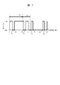
- FIG. 6 is an explanatory diagram of a method for generating an asynchronous pulse signal P according to the second embodiment of the present invention.
- the graph shown in (a) represents the counter value of the PWM timer
- the graph shown in (b) represents the modulated wave signal
- the graph shown in (c) represents the PWM pulse train output as the asynchronous pulse signal P. shows an example.
- the graphs of FIGS. 6A and 6B are the same as the graphs of FIGS. 3A and 3B described in the first embodiment, respectively.
- the asynchronous pulse signal P in the present embodiment has zero crossing points (phase angles 0°, 180°) where the modulated wave reverses from negative to positive or from positive to negative across 0, and pulse phase angles ⁇ 1, ⁇ 2,
- the ON/OFF states of the signals are switched at ⁇ 3, ⁇ 4, ⁇ 1′, ⁇ 2′, ⁇ 3′, and ⁇ 4′, respectively.
- the pulse phase angles ⁇ 1, ⁇ 2, ⁇ 1′, and ⁇ 2′ are obtained by the equations (2) to (5) explained in the first embodiment.
- the pulse phase angles ⁇ 3, ⁇ 4, ⁇ 3', and ⁇ 4' are obtained by the following equations (8) to (11), respectively.
- p is an arbitrary number satisfying 0 ⁇ p ⁇ 1 and is set in advance.
- ⁇ 3 p ⁇ 1
- ⁇ 4 ⁇ 3 (9)
- ⁇ 3′ ⁇ + ⁇ 3 (10)
- ⁇ 4′ 2 ⁇ 3 (11)
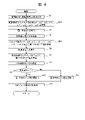
- FIG. 8 is a flowchart of PWM pulse control according to the second embodiment of the present invention.
- the PWM pulse generator 250 performs PWM pulse control by executing the process shown in the flowchart of FIG. Output to the signal generator 260 .
- step S2A the PWM pulse generator 250 uses the pulse phase angle calculator 53 to calculate the pulse phase angle ⁇ based on the modulation factor MF obtained in step S1.
- step S2A is performed by calculating the pulse phase angles ⁇ 3, ⁇ 4, ⁇ 3′, and ⁇ 4′, respectively.
- step S5A the PWM pulse generation unit 250 causes the pulse setting unit 56 to set timer values ( 1st PWM timer value) is set in the PWM timer.
- timer values 1st PWM timer value
- the inverters included in the period from the current control processing timing to the next control processing timing Identify the voltage phase range of the fundamental wave of the output voltage.
- the ON/OFF switching timing of the PWM pulse signal Pr can be set based on the pulse phase angle ⁇ , voltage phase ⁇ v, and phase change width ⁇ obtained in steps S2A to S4.
- the PWM pulse generation unit 250 generates a PWM pulse signal asynchronous with the control period, and the basic inverter output voltage Satisfies the pulse generation condition that at least three or more pulses exist in one cycle of the wave and that the PWM pulse signal is switched on/off at the zero cross point where the fundamental wave of the inverter output voltage changes across 0. to generate the PWM pulse signal Pr.
- the basic inverter output voltage Satisfies the pulse generation condition that at least three or more pulses exist in one cycle of the wave and that the PWM pulse signal is switched on/off at the zero cross point where the fundamental wave of the inverter output voltage changes across 0. to generate the PWM pulse signal Pr.
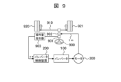
- FIG. 9 is a configuration diagram of an electric power steering device to which the inverter control device 200 shown in one embodiment of the present invention is applied.
- the electric actuator of the electric power steering consists of a torque transmission mechanism 902, a motor 300, an inverter 100, and an inverter control device 200, as shown in FIG.
- the electric power steering apparatus includes an electric actuator, a steering wheel (steering) 900, a steering detector 901, and an operation amount commander 903, and the electric actuator is used to torque-assist the operation force of the steering wheel 900 steered by the driver.
- a torque command ⁇ * for the electric actuator is created by the operation amount commander 903 as a steering assist torque command for the steering wheel 900 .
- the driver's steering force is reduced using the output of the electric actuator driven by the torque command ⁇ *.
- Inverter control device 200 receives a torque command ⁇ * as an input command, controls the operation of inverter 100 to follow the torque command value from the torque constant of motor 300 and torque command ⁇ *, and controls the current flowing through motor 300. to control.
- the motor output ⁇ m output from the output shaft directly connected to the rotor of the motor 300 transmits torque to the rack 910 of the steering device via a torque transmission mechanism 902 using a reduction mechanism such as a worm, a wheel, or a planetary gear or a hydraulic mechanism. do. Due to the torque transmitted to the rack 910, the driver's steering force (operating force) of the steering wheel 900 is reduced (assisted) by electric force, and the steering angles of the wheels 920 and 921 are manipulated.
- a reduction mechanism such as a worm, a wheel, or a planetary gear or a hydraulic mechanism.
- This assist amount is determined as follows. That is, a steering angle and steering torque are detected by a steering detector 901 incorporated in the steering shaft, and a torque command ⁇ * is calculated by an operation amount commander 903 in consideration of state quantities such as vehicle speed and road surface conditions.
- the inverter control device 200 has the advantage of being able to reduce vibration and noise by averaging the output voltage of the inverter 100 even when the motor 300 rotates at high speed.
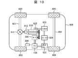
- FIG. 10 is a diagram showing an electric vehicle 600 to which the inverter control device 200 according to the invention is applied.
- Electric vehicle 600 has a powertrain using motor 300 as a motor/generator.
- a front wheel axle 601 is rotatably supported on the front part of the electric vehicle 600, and front wheels 602 and 603 are provided at both ends of the front wheel axle 601.
- a rear wheel axle 604 is rotatably supported at the rear portion of the electric vehicle 600 , and rear wheels 605 and 606 are provided at both ends of the rear wheel axle 604 .
- a differential gear 611 serving as a power distribution mechanism is provided at the central portion of the front wheel axle 601 to distribute the rotational driving force transmitted from the engine 610 via the transmission 612 to the left and right front wheel axles 601 .
- Engine 610 and motor 300 are mechanically connected via a belt that spans between a pulley provided on the crankshaft of engine 610 and a rotation shaft of motor 300 .
- the rotational driving force of the motor 300 can be transmitted to the engine 610, and the rotational driving force of the engine 610 can be transmitted to the motor 300, respectively.
- the rotor rotates when the three-phase AC power output from inverter 100 is supplied to the stator coils of the stator under the control of inverter control device 200, and rotational driving force corresponding to the three-phase AC power is generated. occurs.
- the motor 300 operates as an electric motor under the control of the inverter control device 200, and operates as a generator that generates three-phase AC power by rotating the rotor under the rotational driving force of the engine 610.
- Inverter 100 is a power conversion device that converts DC power supplied from high-voltage battery 622, which is a high-voltage (42 V or 300 V) system power supply, into three-phase AC power. , controls the three-phase alternating current flowing through the stator coils of the motor 300 .
- the three-phase AC power generated by the motor 300 is converted into DC power by the inverter 100 to charge the high-voltage battery 622 .
- the high voltage battery 622 is electrically connected to the low voltage battery 623 via a DC-DC converter 624 .
- the low-voltage battery 623 constitutes a low-voltage (14v) system power supply for the electric vehicle 600, and is used as a power supply for a starter 625 for initial starting (cold starting) of the engine 610, a radio, lights, and the like.
- the engine 610 In the idle stop mode, if the high-voltage battery 622 is insufficiently charged, or if the engine 610 is not warm enough, the engine 610 continues to run without being stopped. Further, during the idle stop mode, it is necessary to secure a drive source for auxiliary equipment such as an air conditioner compressor that uses the engine 610 as a drive source. In this case, the motor 300 is driven to drive the accessories.
- auxiliary equipment such as an air conditioner compressor that uses the engine 610 as a drive source.
- the motor 300 is driven to assist the driving of the engine 610 even in the acceleration mode or the high-load operation mode. Conversely, in a charging mode that requires charging of high-voltage battery 622 , engine 610 causes motor 300 to generate power to charge high-voltage battery 622 . That is, motor 300 is regeneratively operated when electric vehicle 600 is braked or decelerated.
- An electric vehicle 600 includes an inverter control device 200 that generates a PWM pulse for converting a DC voltage into an AC voltage based on a motor output request, and a motor 300 that converts the DC voltage into an AC voltage using the generated PWM pulse. and a DC/DC converter 624 for stepping up the DC voltage.
- Inverter control device 200 generates synchronous 3 pulses and synchronous 1 pulses in synchronization with rotational speed ⁇ r of motor 300 from asynchronous PWM in which rotational speed ⁇ r of motor 300 and carrier wave Tr are asynchronous by the processing of PWM pulse generation unit 250 as described above.
- a single pulse generation logic is used to generate the PWM pulse signal Pr to reduce the output voltage error of the inverter under operating conditions where the number of PWM pulses is small. As a result, it is possible to reduce the DC component and low-order harmonic component of the motor current generated in the zero-cross vicinity region, and to achieve low noise and low vibration of the electric vehicle 600 .
- the inverter control device 200 of the present invention includes a PWM pulse generator 250 that generates a PWM pulse signal Pr for controlling the inverter 100 at each predetermined control cycle.
- the PWM pulse generator 250 generates a PWM pulse signal asynchronous with the control cycle, while at least three or more pulses exist in one cycle of the fundamental wave of the output voltage of the inverter 100, and the fundamental wave is zero.
- the PWM pulse signal Pr is generated so as to satisfy the pulse generation condition that the ON/OFF state of the PWM pulse signal Pr is switched at the zero-cross point that changes across. With this configuration, it is possible to reduce the DC component and the low-order harmonic component of the inverter output current generated in the zero-cross vicinity region. As a result, it is possible to reduce the DC component and the low-order harmonic component of the inverter output current generated in the motor operating state in which the number of PWM pulses is small.
- the PWM pulse generator 250 calculates the modulation factor MF of the inverter output voltage (step S1), and sets each pulse width of the PWM pulse signal Pr based on the modulation factor MF. (step S2). With this configuration, the PWM pulse signal Pr can be easily generated by arithmetic processing using a microcomputer or the like.
- the PWM pulse generator 250 includes a modulation factor calculator 51 that calculates the modulation factor MF, and a pulse phase angle ⁇ that calculates the pulse phase angle ⁇ that switches the ON/OFF state of the PWM pulse signal Pr based on the modulation factor MF.
- Inverter 100 is connected to motor 300 .
- PWM pulse generation unit 250 generates a first PWM pulse signal (asynchronous pulse signal P) that satisfies the above pulse generation conditions, or a voltage command (Vd*, Vq*) to inverter 100 based on the operating state of motor 300 . and a second PWM pulse signal (synchronization pulse signal P') based on comparison with a carrier signal (carrier wave Tr) that periodically changes at a predetermined carrier period Tc (step S8 ⁇ S12). Since this is done, the optimum PWM control mode is selected based on the operating state of the motor 300, and the PWM pulse signal Pr corresponding to the selected PWM control mode is output from the PWM pulse generator 250 to the drive signal generator 260. Thus, the inverter 100 can be controlled.
- the PWM pulse generator 250 generates the PWM pulse signal Pr such that the number of pulses present in one cycle of the fundamental wave of the inverter output voltage is an odd number. With this configuration, it is possible to generate the PWM pulse signal Pr capable of reliably reducing the low-order harmonic components of the inverter output voltage.
- the electric vehicle 600 of one embodiment is a hybrid vehicle
- similar effects can be obtained in the case of a plug-in hybrid vehicle, an electric vehicle, or the like.
- the inverter control device alone has been described.
- the present invention can also be applied to a motor drive system that has
Landscapes
- Engineering & Computer Science (AREA)
- Power Engineering (AREA)
- Transportation (AREA)
- Mechanical Engineering (AREA)
- Chemical & Material Sciences (AREA)
- Combustion & Propulsion (AREA)
- Inverter Devices (AREA)
- Control Of Ac Motors In General (AREA)
Abstract
Description
本発明による電動パワーステアリングシステムは、インバータ制御装置と、前記インバータ制御装置により制御される前記インバータと、前記インバータにより駆動される交流モータと、を備え、前記交流モータを用いて車両のステアリングを制御する。
本発明による電動車両システムは、インバータ制御装置と、前記インバータ制御装置により制御される前記インバータと、前記インバータにより駆動される交流モータと、を備え、前記交流モータの駆動力を用いて走行する。
図1は、本発明の第1の実施形態に係るインバータ制御装置200を有するモータ装置1の構成を示すブロック図である。モータ装置1は、バッテリ2と接続されており、インバータ100、インバータ制御装置200およびモータ300を有している。

α1=arccos{(1+MF)/2} ・・・(2)
α2=π-α1 ・・・(3)
α1’=π+α1 ・・・(4)
α2’=2π-α1 ・・・(5)
θv=θ+arctan(Vq*/Vd*) ・・・(6)
Δθ=ωr/fc ・・・(7)
次に、本発明の第2の実施形態について説明する。本実施形態では、非同期パルス信号Pにおいて、インバータ出力電圧の基本波1周期当たりのパルス数Nが5である場合について説明する。なお、本実施形態におけるインバータ制御装置やモータ制御装置の構成、インバータ制御装置内のPWMパルス生成部の機能構成は、第1の実施形態で説明した図1、図2とそれぞれ同様である。したがって以下では、図1、図2の構成を用いて本実施形態の説明を行うものとする。
α3=p×α1 ・・・(8)
α4=π-α3 ・・・(9)
α3’=π+α3 ・・・(10)
α4’=2π-α3 ・・・(11)
2…バッテリ
51…変調率演算部
52…回転速度算出部
53…パルス位相角演算部
54…電圧位相演算部
55…位相変化幅演算部
56…パルス設定部
57…dq/三相変換部
58…キャリア波演算部
59…PWM制御部
60…PWM制御モード判定部
100…インバータ
200…インバータ制御装置
210…電流制御部
250…PWMパルス生成部
260…ドライブ信号生成部
270…回転位置検出部
280…電流検出部
300…モータ
320…回転位置センサ
600…電動車両
Claims (7)
- インバータを制御するためのPWMパルス信号を所定の制御周期ごとに生成するPWMパルス生成部を備え、
前記PWMパルス生成部は、前記制御周期と非同期のPWMパルス信号を生成しながら、前記インバータの出力電圧の基本波の1周期中に少なくとも3つ以上のパルスが存在し、かつ、前記基本波が0を跨いで変化するゼロクロス点において前記PWMパルス信号のオン/オフ状態が切り替わるというパルス生成条件を満たすように、前記PWMパルス信号を生成するインバータ制御装置。 - 請求項1に記載のインバータ制御装置において、
前記PWMパルス生成部は、前記出力電圧の変調率を演算し、前記変調率に基づいて前記PWMパルス信号の各パルス幅を設定するインバータ制御装置。 - 請求項2に記載のインバータ制御装置において、
前記PWMパルス生成部は、
前記変調率を演算する変調率演算部と、
前記変調率に基づいて前記PWMパルス信号のオン/オフ状態を切り替えるパルス位相角を演算するパルス位相角演算部と、
前記出力電圧の位相角に応じた電圧位相を演算する電圧位相演算部と、
前記制御周期における前記出力電圧の位相変化幅を演算する位相変化幅演算部と、
前記パルス位相角、前記電圧位相および前記位相変化幅に基づいて、前記PWMパルス信号のオン/オフ状態の切替タイミングを設定するパルス設定部と、を備えるインバータ制御装置。 - 請求項1に記載のインバータ制御装置において、
前記インバータは、モータに接続されており、
前記PWMパルス生成部は、前記モータの運転状態に基づいて、前記パルス生成条件を満たす第1のPWMパルス信号、または、前記インバータに対する電圧指令と所定のキャリア周期で周期的に変化するキャリア信号との比較に基づく第2のPWMパルス信号、のいずれかを選択的に出力するインバータ制御装置。 - 請求項1に記載のインバータ制御装置において、
前記PWMパルス生成部は、前記出力電圧の基本波の1周期中に存在するパルスの数が奇数となるように、前記PWMパルス信号を生成するインバータ制御装置。 - 請求項1から請求項5のいずれか一項に記載のインバータ制御装置と、
前記インバータ制御装置により制御される前記インバータと、
前記インバータにより駆動される交流モータと、を備え、
前記交流モータを用いて車両のステアリングを制御する電動パワーステアリングシステム。 - 請求項1から請求項5のいずれか一項に記載のインバータ制御装置と、
前記インバータ制御装置により制御される前記インバータと、
前記インバータにより駆動される交流モータと、を備え、
前記交流モータの駆動力を用いて走行する電動車両システム。
Priority Applications (3)
| Application Number | Priority Date | Filing Date | Title |
|---|---|---|---|
| US18/686,201 US12700819B2 (en) | 2021-09-13 | 2022-02-15 | Inverter control device, electric power steering system, and electric vehicle system |
| DE112022002989.7T DE112022002989T5 (de) | 2021-09-13 | 2022-02-15 | Wechselrichter-Steuervorrichtung, elektrische Servolenkung und Elektrofahrzeugsystem |
| CN202280054826.9A CN117813758A (zh) | 2021-09-13 | 2022-02-15 | 逆变器控制装置、电动助力转向系统、电动车辆系统 |
Applications Claiming Priority (2)
| Application Number | Priority Date | Filing Date | Title |
|---|---|---|---|
| JP2021-149005 | 2021-09-13 | ||
| JP2021149005A JP7676084B2 (ja) | 2021-09-13 | 2021-09-13 | インバータ制御装置、電動パワーステアリングシステム、電動車両システム |
Publications (1)
| Publication Number | Publication Date |
|---|---|
| WO2023037579A1 true WO2023037579A1 (ja) | 2023-03-16 |
Family
ID=85507331
Family Applications (1)
| Application Number | Title | Priority Date | Filing Date |
|---|---|---|---|
| PCT/JP2022/005924 Ceased WO2023037579A1 (ja) | 2021-09-13 | 2022-02-15 | インバータ制御装置、電動パワーステアリングシステム、電動車両システム |
Country Status (5)
| Country | Link |
|---|---|
| US (1) | US12700819B2 (ja) |
| JP (1) | JP7676084B2 (ja) |
| CN (1) | CN117813758A (ja) |
| DE (1) | DE112022002989T5 (ja) |
| WO (1) | WO2023037579A1 (ja) |
Families Citing this family (1)
| Publication number | Priority date | Publication date | Assignee | Title |
|---|---|---|---|---|
| US12122251B2 (en) * | 2022-09-28 | 2024-10-22 | BorgWarner US Technologies LLC | Systems and methods for bidirectional message architecture for inverter for electric vehicle |
Citations (3)
| Publication number | Priority date | Publication date | Assignee | Title |
|---|---|---|---|---|
| JPS6216076A (ja) * | 1985-07-10 | 1987-01-24 | Hitachi Ltd | 電流形インバ−タの制御装置 |
| JP2018133935A (ja) * | 2017-02-16 | 2018-08-23 | 日立オートモティブシステムズ株式会社 | インバータ装置および電動車両 |
| JP2021052442A (ja) * | 2019-09-20 | 2021-04-01 | 日立Astemo株式会社 | インバータ制御装置 |
Family Cites Families (7)
| Publication number | Priority date | Publication date | Assignee | Title |
|---|---|---|---|---|
| ZA949795B (en) * | 1993-12-17 | 1995-08-18 | Hitachi Ltd | Electric power conversion equipment. |
| JPH09308256A (ja) | 1996-05-14 | 1997-11-28 | Hitachi Ltd | Pwmインバータ装置 |
| JP6062327B2 (ja) | 2013-07-09 | 2017-01-18 | 日立オートモティブシステムズ株式会社 | インバータ装置および電動車両 |
| JP6361178B2 (ja) * | 2014-03-07 | 2018-07-25 | 株式会社ジェイテクト | モータ制御装置及び電動パワーステアリング装置 |
| JP6116538B2 (ja) | 2014-11-28 | 2017-04-19 | 株式会社豊田中央研究所 | モータ制御装置 |
| JP6581373B2 (ja) | 2015-03-24 | 2019-09-25 | 株式会社日立産機システム | モータ制御装置 |
| JP2016185021A (ja) | 2015-03-26 | 2016-10-20 | Ntn株式会社 | インバータ装置 |
-
2021
- 2021-09-13 JP JP2021149005A patent/JP7676084B2/ja active Active
-
2022
- 2022-02-15 CN CN202280054826.9A patent/CN117813758A/zh active Pending
- 2022-02-15 WO PCT/JP2022/005924 patent/WO2023037579A1/ja not_active Ceased
- 2022-02-15 US US18/686,201 patent/US12700819B2/en active Active
- 2022-02-15 DE DE112022002989.7T patent/DE112022002989T5/de active Pending
Patent Citations (3)
| Publication number | Priority date | Publication date | Assignee | Title |
|---|---|---|---|---|
| JPS6216076A (ja) * | 1985-07-10 | 1987-01-24 | Hitachi Ltd | 電流形インバ−タの制御装置 |
| JP2018133935A (ja) * | 2017-02-16 | 2018-08-23 | 日立オートモティブシステムズ株式会社 | インバータ装置および電動車両 |
| JP2021052442A (ja) * | 2019-09-20 | 2021-04-01 | 日立Astemo株式会社 | インバータ制御装置 |
Also Published As
| Publication number | Publication date |
|---|---|
| DE112022002989T5 (de) | 2024-04-04 |
| US12700819B2 (en) | 2026-08-04 |
| JP2023041564A (ja) | 2023-03-24 |
| US20250192711A1 (en) | 2025-06-12 |
| JP7676084B2 (ja) | 2025-05-14 |
| CN117813758A (zh) | 2024-04-02 |
Similar Documents
| Publication | Publication Date | Title |
|---|---|---|
| JP6062327B2 (ja) | インバータ装置および電動車両 | |
| US12074551B2 (en) | Motor control device, electromechanical unit, electric vehicle system, and motor control method | |
| JP7247065B2 (ja) | インバータ制御装置 | |
| US10826410B2 (en) | Inverter device and electric vehicle | |
| CN105471359B (zh) | 车辆控制装置 | |
| US10873285B2 (en) | Inverter drive device and electrically driven vehicle system using the same | |
| US12562657B2 (en) | Inverter control device, hybrid system, electromechanical integrated unit, electric vehicle system, and inverter control method | |
| JP7494393B2 (ja) | モータ制御装置、機電一体ユニット、ハイブリッドシステム、電動パワーステアリングシステム、およびモータ制御方法 | |
| JP7676084B2 (ja) | インバータ制御装置、電動パワーステアリングシステム、電動車両システム | |
| JP7382890B2 (ja) | インバータ制御装置、電動車両システム | |
| US10348234B2 (en) | Drive system, automobile, and method of controlling drive system | |
| JP2008072858A (ja) | 車両用回転電機の制御装置 |
Legal Events
| Date | Code | Title | Description |
|---|---|---|---|
| 121 | Ep: the epo has been informed by wipo that ep was designated in this application |
Ref document number: 22866914 Country of ref document: EP Kind code of ref document: A1 |
|
| WWE | Wipo information: entry into national phase |
Ref document number: 202280054826.9 Country of ref document: CN |
|
| WWE | Wipo information: entry into national phase |
Ref document number: 112022002989 Country of ref document: DE |
|
| WWE | Wipo information: entry into national phase |
Ref document number: 18686201 Country of ref document: US |
|
| WWE | Wipo information: entry into national phase |
Ref document number: 202417015806 Country of ref document: IN |
|
| 122 | Ep: pct application non-entry in european phase |
Ref document number: 22866914 Country of ref document: EP Kind code of ref document: A1 |
|
| WWP | Wipo information: published in national office |
Ref document number: 18686201 Country of ref document: US |
|
| WWG | Wipo information: grant in national office |
Ref document number: 18686201 Country of ref document: US |