WO2023037550A1 - ロボット、ロボットシステム、制御方法及びプログラム - Google Patents
ロボット、ロボットシステム、制御方法及びプログラム Download PDFInfo
- Publication number
- WO2023037550A1 WO2023037550A1 PCT/JP2021/033565 JP2021033565W WO2023037550A1 WO 2023037550 A1 WO2023037550 A1 WO 2023037550A1 JP 2021033565 W JP2021033565 W JP 2021033565W WO 2023037550 A1 WO2023037550 A1 WO 2023037550A1
- Authority
- WO
- WIPO (PCT)
- Prior art keywords
- joints
- joint
- robot
- command
- target
- Prior art date
Links
- 238000000034 method Methods 0.000 title claims description 77
- 239000011159 matrix material Substances 0.000 claims description 37
- 230000033001 locomotion Effects 0.000 claims description 9
- 230000004044 response Effects 0.000 claims description 5
- 238000001514 detection method Methods 0.000 claims description 3
- 230000008569 process Effects 0.000 description 66
- 238000004364 calculation method Methods 0.000 description 35
- 230000006870 function Effects 0.000 description 32
- 230000010365 information processing Effects 0.000 description 16
- 238000010586 diagram Methods 0.000 description 14
- 238000004891 communication Methods 0.000 description 10
- 230000001133 acceleration Effects 0.000 description 4
- 230000006866 deterioration Effects 0.000 description 4
- 210000000245 forearm Anatomy 0.000 description 2
- 210000003128 head Anatomy 0.000 description 2
- 230000004048 modification Effects 0.000 description 2
- 238000012986 modification Methods 0.000 description 2
- 230000009471 action Effects 0.000 description 1
- 230000008859 change Effects 0.000 description 1
- 238000004590 computer program Methods 0.000 description 1
- 210000001061 forehead Anatomy 0.000 description 1
- 230000005484 gravity Effects 0.000 description 1
- 238000004519 manufacturing process Methods 0.000 description 1
- 230000000007 visual effect Effects 0.000 description 1
Images


Classifications
-
- B—PERFORMING OPERATIONS; TRANSPORTING
- B25—HAND TOOLS; PORTABLE POWER-DRIVEN TOOLS; MANIPULATORS
- B25J—MANIPULATORS; CHAMBERS PROVIDED WITH MANIPULATION DEVICES
- B25J13/00—Controls for manipulators
-
- B—PERFORMING OPERATIONS; TRANSPORTING
- B25—HAND TOOLS; PORTABLE POWER-DRIVEN TOOLS; MANIPULATORS
- B25J—MANIPULATORS; CHAMBERS PROVIDED WITH MANIPULATION DEVICES
- B25J9/00—Programme-controlled manipulators
Definitions
- the present invention relates to a robot with multiple joints, a system including the robot, a robot control method, a control program, or the like.
- a method of giving commands to each joint in a joint coordinate system and a method of giving a command in a Cartesian coordinate system are used in a predetermined target point (for example, , hand position, TCP (Tool Center Point), etc.), and perform inverse kinematics calculations, etc., to interlock and control each joint.
- a predetermined target point for example, , hand position, TCP (Tool Center Point), etc.
- interlocking control may be applied only to some of them depending on the hardware configuration. For example, in a dual-arm robot, as if the robot arm were simply attached to the main body, the arms and body were controlled separately, and interlocking control was applied only to the arms. In rare cases, interlocking control may be applied to all joints of a multi-joint robot such as a dual-arm robot.
- the present invention has been made in view of the above-described technical background, and its object is to provide a robot, etc., capable of preventing a decrease in workability or redundant control when interlocking control is applied to joints. is to provide
- a robot according to the present invention is a robot having a plurality of joints, and sets some or all of the plurality of joints as target joints for interlocking control according to a switching signal. and a controller that interlocks and controls the target joint.
- each joint can be controlled in conjunction by solving inverse kinematics from the command to the target point.
- a command in the joint coordinate system may be issued to joints other than the target joint among the plurality of joints.
- some joints can be interlockedly controlled, and other joints can be individually controlled by commands in the joint coordinate system.
- the target point may be TCP.
- the TCP (tool center point) can be freely controlled.
- the target point may be a virtual point separated from the robot.
- the robot may include a torso and a pair of arms extending from the left and right of the torso.
- the target joints may include joints related to both of the arms and joints related to the trunk.
- the mode set by the switching signal includes a first mode in which the joint related to one of the arms and the joint related to the trunk are the target joints, the joint related to both the arms, and the It may include a second mode in which a joint related to the torso is set as the target joint.
- the target joint may include a plurality of joint groups.
- a system according to the present invention is a system that includes a robot having a plurality of joints, and sets some or all of the plurality of joints as target joints for interlocking control in response to a switching signal.
- a setting unit and a control unit that interlock-controls the target joint are provided.
- a method according to the present invention is a method for controlling a robot having a plurality of joints, wherein some or all of the plurality of joints are set as target joints for interlocking control according to a switching signal.
- the method includes a setting step and a control step of interlockingly controlling the target joint.
- FIG. 1 is an overall configuration diagram of a robot system 300 according to this embodiment. As is clear from the figure, in this embodiment, the dual-arm robot 1 is connected to the information processing device 5 by wire or wirelessly to form a robot system 300 .
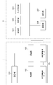
- FIG. 2 is an explanatory diagram regarding joint arrangement of the dual-arm robot 1.
- FIG. As is clear from the figure, in the center of the figure, a trunk portion 11 extending vertically upward from the ground plane is arranged. A head portion 19 is connected to the upper end of the body portion 11 via a neck portion 18 .
- a right arm 12 is connected to the upper end of the right side of the body 11 , and a left arm 14 is connected to the upper end of the left side of the body 11 .
- the torso 11 has a first torso joint (T_J1) that rotates the upper part (upper body) of the torso 11 to the left and right, and a second torso joint (T_J1) that tilts the upper part of the torso 11 forward or backward. T_J2) is provided.
- the right arm 12 has 7 degrees of freedom. That is, the right arm first rotation joint (R_J1) that rotates the right arm 12 around an axis that extends horizontally from the root of the right arm 12 to the trunk 11, and from the vicinity of the center of the shoulder of the right arm 12
- the second right arm joint (R_J2) that rotates around the axis extending forward
- the third right arm joint that is located in the upper arm directly below the second right arm joint and rotates the elbow and below around the central axis in the longitudinal direction. (R_J3).
- the right arm 12 includes a right arm fourth joint (R_J4) that rotates the forearm around an axis that extends forward from the vicinity of the center of the elbow of the right arm 12, and a forearm directly below the right arm fourth joint.
- the right arm fifth joint (R_J5) that rotates the hand around the central axis in the longitudinal direction, and the right arm that rotates around the axis orthogonal to the longitudinal direction, which is located near the tip position from the right arm fifth joint. It has a sixth joint (R_J6) and a seventh joint (R_J7) that rotates about an axis extending forward from near the center of the hand.
- FIG. 3 is a functional block diagram of the robot system 300.
- the information processing device 5 includes a control section 501 , a storage section 502 , an input reception section 503 , a communication section 506 and a display section 507 .
- the control unit 501 is an arithmetic processing unit such as a CPU, and executes the loaded program.
- the storage unit 502 is a storage device such as ROM/RAM, hard disk, flash memory, etc., and stores programs and various data described later, such as joint information and setting information required for operation in each mode.
- the input reception unit 503 performs processing for receiving input from an operator, administrator, user, or the like.
- a communication unit 506 is a communication unit and performs communication with the dual-arm robot 1 .
- a display unit 507 performs processing for displaying image information on a display (not shown) or the like.
- the dual-arm robot 1 includes a storage unit 101, a control unit 102, a communication unit 103, and a plurality of joint drive units 105 (T_J1, T_J2, L_J1 to L_J7, R_J1 to R_J7) that drive the joints of the dual-arm robot 1. It has although not shown, each joint of the dual-arm robot 1 is provided with a sensor for acquiring various information such as the angle, angular velocity, angular acceleration, current value, and torque value of each joint. is provided to the control unit 102 .
- the storage unit 101 and the control unit 102 constitute a microcomputer, the storage unit 101 is a storage device such as ROM/RAM, and the control unit 102 is an arithmetic processing device such as a CPU.
- the communication unit 103 is a communication unit that exchanges information with the communication unit 506 of the information processing device 5 .
- Each joint driving unit 105 is controlled by the control unit 102 to drive each joint.
- FIG. 4 is a general flow chart for the operation of robotic system 300 .
- the control unit 501 executes a process of displaying a mode acceptance display via the display unit 507 (S1).
- This mode acceptance display includes a display for prompting the operator or the like to select one of the modes.
- the information processing device 5 enters a standby state until it receives a mode selection signal (or mode switching signal) input via the input reception unit 503 (S2 NO).
- each mode start operation is executed. That is, a process for starting the corresponding mode according to the detected mode selection signal is performed (S3).
- the control unit 501 executes the first mode start process (S5).
- the second mode start process is executed (S6).
- a third mode start process is executed (S7).
- fourth mode start processing is executed (S9). Each process described later is executed by these mode start processes.
- control unit 501 repeats the series of operations again (S1 to S9).
- FIG. 5 is a detailed flowchart regarding the first mode executed by the first mode start process (S5).
- the control unit 501 performs a process of reading joint information related to the first mode from the storage unit 502 (S501).
- Joint information is information indicating what kind of control is applied to which joint.
- This setting information includes hardware information of the dual-arm robot 1 such as link lengths of each part of the dual-arm robot 1 and link parameters (L) representing the relationship between links, information on the origin (O, O L ') and Information (TCP(L), TCP(R)) on the left and right TCPs (Tool Center Points), which are target points to be controlled, is included.
- the origin O is set at the central ground plane of the body 11 and TCP(R) is set near the tip of the right arm 12 .
- the origin O L ′ is set at the root of the left arm 14
- TCP(L) is set near the tip of the left arm 14 .
- the kinematic chain refers to a series of interlocking joints existing from the origin O to the TCP.
- This kinematic chain is specifically specified by specifying the joint variable vector (q) and the link parameter (L).
- FIG. 6 is a conceptual diagram of the kinematic chain according to the first mode.
- an arrow is shown from the origin O to TCP(R) via the trunk joint (T_J1 ⁇ T_J2), the right arm joint (R_J1 ⁇ R_J2 ⁇ ... ⁇ R_J7).
- a series of joints existing from the origin O to TCP(R) is specified as a kinematic chain used for interlocking control of the torso 11 and right arm 12 .
- the control unit 501 performs a current value acquisition process for each joint of the dual-arm robot 1 (S503).
- the current values related to joints are the current values of angles, angular velocities, angular accelerations, current values, torque values, etc. of each joint acquired by predetermined sensors provided in the dual-arm robot 1 .
- the control unit 501 After the Jacobian matrix calculation process, the control unit 501 performs a command value acquisition process for TCP(R) (S507).
- the command value is acquired by reading from the storage unit 502 .
- the command value is not limited to that shown in this embodiment, and for example, the command value may be generated according to information from various sensors such as a camera.
- the information processing device 5 and the dual-arm robot 1 work together to solve the inverse kinematics based on the command value in the Cartesian coordinate system for TCP(R) and the Jacobian matrix to obtain the torso Interlocking control processing of joints (T_J1, T_J2) and right arm joints (R_J1, R_J2, . . . , R_J7), for example, position control of each joint is performed (S508). After that, the process proceeds to the end determination process (S510).
- the control unit 501 performs calculation processing of a function related to forward kinematics for the kinematic chain from the origin O to TCP(L) for the left arm 14 (S511). That is, as is widely known to those skilled in the art, the nonlinear vector function f(q, L ) is calculated.
- the control unit 501 After the Jacobian matrix calculation process, the control unit 501 performs a command value acquisition process for the left arm joint (S513).
- the command value is acquired by reading from the storage unit 502 .
- the command value is not limited to that shown in this embodiment, and for example, the command value may be generated according to information from various sensors such as a camera.
- the information processing device 5 and the dual-arm robot 1 cooperate to perform desired position control based on the command values in the joint coordinate system for each joint. For example, control may be performed such that each joint of the left arm 14 is held.
- FIG. 7 is a detailed flowchart regarding the third mode executed by the third mode start process (S7).
- the control unit 501 performs current value acquisition processing for each joint (S703).
- the current values related to joints are the current values of angles, angular velocities, angular accelerations, current values, torque values, etc. of each joint acquired by predetermined sensors provided in the dual-arm robot 1 .
- the control unit 501 After the Jacobian matrix calculation process, the control unit 501 performs a command value acquisition process for TCP(R) and TCP(L) (S707).
- the command value is acquired by reading from the storage unit 502 .
- the command value is not limited to that shown in this embodiment, and for example, the command value may be generated according to information from various sensors such as a camera.
- the information processing device 5 and the dual-arm robot 1 cooperate to solve the inverse kinematics using the calculated Jacobian matrix J to obtain the right arm joints (R_J1 to R_J7) and the left arm joints (L_J1 to L_J7) and trunk joints (T_J1, T_J2) are interlocked and controlled (S708).
- a desired position command in the Cartesian coordinate system is issued to the TCP (R) associated with the right arm 12 and the TCP (L) associated with the left arm 14 to control each joint.
- position commands in the Cartesian coordinate system are issued to each TCP, but the present invention is not limited to such a configuration, and commands may be issued in other modes.
- commands may be issued in other modes.
- velocity commands, current commands, force commands, or moment commands may be made in the Cartesian coordinate system for each TCP.
- a point other than the TCP such as an arbitrary hand position, may be set as the target point.
- inverse kinematics calculation is performed for interlocking control, but the present invention is not limited to such a configuration. Therefore, for example, impedance control or the like may be performed without performing inverse kinematics calculations. Also, in the present embodiment, the Jacobian matrix is used, but the present invention is not limited to such a configuration, and control calculation may be performed without using the Jacobian matrix.
- the control processing (S703-S708) for each joint is repeatedly executed until a predetermined end signal is received (S709 NO). On the other hand, if a predetermined end signal has been received (S709YES), the process ends.
- the joints of the whole body can be linked and controlled, so the workability of the dual-arm robot 1 can be improved.
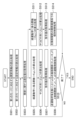
- FIG. 9 is a detailed flowchart regarding the fourth mode executed by the fourth mode start process (S9).
- the control unit 501 performs a process of reading joint information corresponding to the fourth mode from the storage unit 502 (S901). More specifically, in the fourth mode, a plurality of joint groups, that is, the right arm joints (R_J1 to R_J7) and the left arm joints (L_J1 to L_J7) are specified as target joint groups for interlock control. , the corresponding joint variable vector (q) is read. Also, for the trunk joints (T_J1, T_J2), the corresponding joint variable vector (q) is read assuming that desired position control or the like is performed in the joint coordinate system.
- This setting information includes hardware information of the dual-arm robot 1 such as link lengths of each part of the dual-arm robot 1 and link parameters (L) representing the relationship between links, etc.
- the origin O is arranged on the ground plane at the center of the trunk portion 11 .
- the origins O L ' and O R ' for the left and right arms are arranged near the roots of the left and right arms 12 and 14, respectively.
- left and right TCP(R) and TCP(L) are set near the tip of each arm 12 and 14 .
- the control unit 501 performs current value acquisition processing for each joint (S903).
- the current values related to joints are the current values of angles, angular velocities, angular accelerations, current values, torque values, etc. of each joint acquired by predetermined sensors provided in the dual-arm robot 1 .
- the control unit 501 After the joint current value acquisition process, the control unit 501 performs forward kinematic function calculation process for the trunk joints (T_J1, T_J2) (S904). That is, as is widely known to those skilled in the art, a nonlinear vector function that calculates the position and orientation of each origin O L ', O R ' from each joint angle based on the joint variable vector (q) and the link parameter (L) Calculate f(q, L).
- control for the right arm 12, control for the left arm 14, and control for the torso 11 are executed in parallel.
- the control unit 501 performs calculation processing of a function related to forward kinematics for the kinematic chain from the right arm origin O R ' to TCP(R) (S906). That is, based on the joint variable vector (q) and the link parameter (L), a nonlinear vector function f(q, L) for calculating the position and orientation of TCP(R) from each joint angle is calculated.
- the control unit 501 After the Jacobian matrix calculation process, the control unit 501 performs a command value acquisition process for TCP(R) (S908).
- the command value is acquired by reading from the storage unit 502 .
- the command value is not limited to that shown in this embodiment, and for example, the command value may be generated according to information from various sensors such as a camera.
- the information processing device 5 and the dual-arm robot 1 work together to solve inverse kinematics using the calculated Jacobian matrix J, thereby interlocking control of the right arm joints (R_J1 to R_J7). (S909). Specifically, a desired position command in the Cartesian coordinate system is issued to TCP(R) to perform interlocking control.
- a position command in the Cartesian coordinate system is issued to TCP(R), but the present invention is not limited to such a configuration, and commands may be issued in other modes. Therefore, for example, a speed command, current command, force command, or moment command may be given to TCP(R) in the Cartesian coordinate system. Also, a point other than TCP(R), for example, an arbitrary hand position or the like may be set as the target point.
- the interlocking control process for the right arm joint is repeatedly executed until a predetermined end signal is received (S910 NO). On the other hand, if a predetermined end signal has been received (S910YES), the process ends.
- a position command in the Cartesian coordinate system is given to TCP(L), but the present invention is not limited to such a configuration, and commands may be given in other modes. Therefore, for example, a speed command, current command, force command, or moment command in the Cartesian coordinate system may be given to TCP(L). Also, a point other than TCP(L), such as an arbitrary hand position, may be set as the target point.
- inverse kinematics calculation is performed for interlocking control, but the present invention is not limited to such a configuration. Therefore, for example, impedance control or the like may be performed without performing inverse kinematics calculations. Also, in the present embodiment, the Jacobian matrix is used, but the present invention is not limited to such a configuration, and control calculation may be performed without using the Jacobian matrix.
- the interlocking control process for the left arm joint is repeatedly executed until a predetermined end signal is received (S916 NO). On the other hand, if a predetermined end signal has been received (S916YES), the process ends.
- control unit 501 After the command value acquisition process, the control unit 501 performs desired position control for each joint (T_J1, T_J2) of the torso 11 based on the command value in the joint coordinate system (S922).
- FIG. 10 is a conceptual diagram of a kinematic chain according to the fourth mode.
- the kinematic chain according to the fourth mode first, from the origin O along the arrow, through the trunk joint (T_J1 ⁇ T_J2), the left and right arm origins O R ' at the bases of the left and right arms, A kinematic chain up to O L ' is identified.
- the TCP (R) of the right arm 12 After that, toward the TCP (R) of the right arm 12, along the arrow from the right arm origin O R ', through the right arm joints (R_J1 ⁇ R_J2 ⁇ ... ⁇ R_J7) in order, the TCP (R) of the right arm 12 ( A series of joints on the route to R) form a kinematic chain for interlocking control of the right arm 12 .
- the desired joints that is, the right arm joints (R_J1 to R_J7) and the left arm joints (L_J1 to L_J7), are controlled independently of the right arm 12, the left arm 14, and the torso 11. ), interlocking control can be applied. Thereby, the workability of the dual-arm robot 1 can be improved.
- TCP was adopted as the target point for commanding, but the present invention is not limited to such a configuration. Therefore, for example, a point other than the TCP may be used as the target point of the robot, or a virtual point outside the robot housing may be used as the target point for control.
- FIG. 11 is an explanatory diagram regarding commands to virtual points.
- the dual-arm robot 1 described in the first embodiment lifts a rectangular parallelepiped load 21 when it is in the third mode, that is, the whole-body interlocking mode.
- a virtual point that serves as a target point for commanding a position or the like is placed at the middle point (V) between the TCP (R) of the right arm 12 and the TCP (L) of the left arm 14 .
- Whole-body interlocking control can be performed by issuing a command to this intermediate point (V).
- a command for a virtual point when a command for a virtual point is detected, it is converted into a TCP (R) command for the right arm 12 and a TCP (L) command for the left arm 14 . Since subsequent processing is the same as that shown in the first embodiment, detailed description is omitted.
- the dual-arm robot 1 has been described as being in the third mode, but it may be executed in another mode.
- the first to fourth modes are freely switched without any timing restrictions (see FIG. 1), but the present invention is not limited to such a configuration. Therefore, for example, a detection unit is provided to detect whether or not the robot is in motion from information obtained by various sensors provided in the robot. or a warning processing unit that visually or audibly warns the operator or the like.
- switching is performed based on an input to the input reception unit 503, but the present invention is not limited to such a configuration. Therefore, in addition to the input signal from the input reception unit 503, the mode may be automatically switched according to a command from a host system, an external system, or the like, or a predetermined condition determination. Further, instead of directly switching modes, switching may be suggested visually or aurally.
- the information processing device 5 performs the first to second movements accompanied by the interlocking of the torso 11.
- a visual or audible warning may be provided to alert the user to switch to mode 3. Further, along with the warning or independently, the switching process to any one of the first to third modes involving the interlocking of the torso 11 may be performed.
- the unit of control is the torso 11, the right arm 12, or the left arm 14, but the configuration is not limited to this. Therefore, for example, a control unit may be assigned across each part, or a control unit may be assigned to a partial joint group of each part.
- the present invention can be used in industries that manufacture robots and the like.
Landscapes
- Engineering & Computer Science (AREA)
- Robotics (AREA)
- Mechanical Engineering (AREA)
- Manipulator (AREA)
Abstract
複数の関節を備えたロボットであって、切替信号に応じて、前記複数の関節のうちの一部又は全ての関節を連動制御の対象関節として設定する、設定部と、前記対象関節を連動制御する、制御部と、を備えた、ロボットが提供される。
Description
この発明は、複数の関節を備えたロボット、ロボットを含むシステム、ロボットの制御方法、又は、制御プログラム等に関する。
近年、人間類似の作業を可能とするため、産業界において、人間と同様に複数の関節を備えたロボットが注目されている。例えば、胴部と胴部の左右から延びる腕部を備える双腕ロボット等が注目されている(例えば、特許文献1)。
複数の関節を備えたロボットの制御にあたっては、各関節に対して関節座標系において指令を与える方法と、カルテシアン座標系(直交座標系又はデカルト座標系とも呼ばれる)において、所定の目標点(例えば、手先位置やTCP(Tool Center Point)等)に対して基準座標に対する指令を与え、逆運動学計算等を行って、各関節を連動制御する方法が知られている。
ところで、ロボットの持つ関節のうちどの関節に対して連動制御を適用するかについては、従前いくつかの方法論が存在した。より詳細には、従前の複数関節を備えたロボットにおいては、ハードウェア構成に応じて、その一部のみに連動制御が適用されることがあった。例えば、双腕ロボットにおいては、ロボットアームを単に本体部に取り付けたかのように、腕部と胴部とは別々に制御され、腕部に対してのみ連動制御が適用されることがあった。また、稀に、双腕ロボット等の多関節ロボットの備えるすべての関節に対して、連動制御が適用されることもあった。
しかしながら、ロボットの一部の関節のみに対して連動制御が適用されると、作業範囲が限定的となる等により、作業性が低下するおそれがあった。例えば、双腕ロボットにおいて腕部に係る関節のみに対して連動制御が適用されると、胴部の関節等との連携が不十分となり、その結果、作業範囲が限定的となる等して、作業性が低下するおそれがあった。
一方、ロボットのすべての関節に対して連動制御が適用されると、一部の関節のみを使用するタスク等においては、その他の関節に関する制御が冗長となるおそれがあった。例えば、双腕ロボットにおいて、片手でドアを開ける動作のような一部の関節のみを使用するタスクを実行する場合には、開閉に使用しない腕に対する制御が冗長となるおそれがあった。
本発明は上述の技術的背景に鑑みてなされたものであり、その目的は、関節に対して連動制御を適用する場合に、作業性の低下又は冗長な制御を防止することが可能なロボット等を提供することにある。
上述の技術的課題は、以下の構成を有するロボット等により解決することができる。
すなわち、本発明に係るロボットは、複数の関節を備えたロボットであって、切替信号に応じて、前記複数の関節のうちの一部又は全ての関節を連動制御の対象関節として設定する、設定部と、前記対象関節を連動制御する、制御部と、を備えている。
このような構成によれば、連動制御の対象となる関節を切り替えることができるので、作業を行うロボットにおける冗長な制御や作業性の低下を防止することができる。
前記連動制御は、カルテシアン座標系における目標点への指令に基づく制御であってもよい。
このような構成によれば、目標点への指令から逆運動学等を解くことにより各関節を連動して制御することができる。
前記複数の関節のうち、前記対象関節以外の関節に対しては、関節座標系における指令が行われる、ものであってもよい。
このような構成によれば、一部の関節については連動制御させ、その他の関節については、関節座標系における指令により個別制御を行うことができる。
前記目標点は、TCPであってもよい。
このような構成によれば、TCP(ツール・センター・ポイント)を自在に制御することができる。
前記目標点は、前記ロボットから離間した仮想点であってもよい。
このような構成によれば、ロボットの持つ物体の軌道を設定したり、両手動作の生成の容易化等を実現することができる。
前記ロボットは、胴部と前記胴部の左右から延びる一対の腕部とを含む、ものであってもよい。
このような構成によれば、双腕ロボットにおいて、冗長な制御や作業性の低下を防止することができる。
前記対象関節は、前記腕部の一方に係る関節と、前記胴部に係る関節を含む、ものであってもよい。
このような構成によれば、腕部と胴部とを連動させる制御を行うことができる。
前記対象関節は、前記腕部の両方に係る関節と、前記胴部に係る関節を含む、ものであってもよい。
このような構成によれば、全身を連動させる制御を行うことができる。
前記切替信号により設定されるモードは、前記腕部の一方に係る関節と、前記胴部に係る関節を、前記対象関節とする第1のモードと、前記腕部の両方に係る関節と、前記胴部に係る関節を、前記対象関節とする第2のモードを含む、ものであってもよい。
このような構成によれば、腕部と胴部とを連動させる制御と、全身連動制御とを切り替えることができる。
前記対象関節は、複数の関節群を含む、ものであってもよい。
このような構成によれば、関節群毎にそれぞれ連動制御させることができる。
前記指令は、位置指令、速度指令、電流指令、力指令、又は、モーメント指令のいずれか1つを含む、ものであってもよい。
このような構成によれば、目標点に対して様々な指令を適用することができる。
前記切替信号は、前記ロボットのオペレータによって設定される、ものであってもよい。
このような構成によれば、オペレータは、タスク等に応じて連動制御させる関節を切り替えることができる。
前記切替信号は、上位システム又は外部システムにより提供される、ものであってもよい。
このような構成によれば、上位システム又は外部システムの動作に応じて連動制御させる関節を切り替えることができる。
前記切替信号は、前記ロボットの動作に関する条件判定を行うことにより生成される、ものであってもよい。
このような構成によれば、ロボット動作に応じて連動制御する関節を切り替えることができる。
前記条件判定は、前記関節の可動範囲を超えた指令を検出したか否かを含む、ものであってもよい。
このような構成によれば、ロボットの関節の可動範囲を超えた指令があったことを検出して、適応的に連動制御の対象となる関節を切り替えることができる。
前記ロボットが動作しているか否かを検出する、動作検出部と、前記ロボットが動作していると判定される場合には、前記切替信号を無効化する、無効化処理部と、をさらに備えるものであってもよい。
このような構成によれば、動作中はモードの切替を行うことができないので、安全性を向上させることができる。
前記対象関節に対してヤコビ行列を算出する、ヤコビ行列算出部をさらに備え、前記制御部は、前記ヤコビ行列を利用して、前記対象関節を連動制御する、ものであってもよい。
このような構成によれば、切り替えられた対象関節に対して算出されたヤコビ行列を利用して、対象関節を連動制御させることができる。
本発明はシステムとして観念することもできる。本発明に係るシステムは、複数の関節を備えたロボットを含むシステムであって、切替信号に応じて、前記複数の関節のうちの一部又は全ての関節を連動制御の対象関節として設定する、設定部と、前記対象関節を連動制御する、制御部と、を備えている。
本発明は方法として観念することもできる。本発明に係る方法は、複数の関節を備えたロボットの制御方法であって、切替信号に応じて、前記複数の関節のうちの一部又は全ての関節を連動制御の対象関節として設定する、設定ステップと、前記対象関節を連動制御する、制御ステップと、を備えている。
本発明はコンピュータプログラムとして観念することもできる。すなわち、本発明に係るプログラムは、複数の関節を備えたロボットの制御プログラムであって、切替信号に応じて、前記複数の関節のうちの一部又は全ての関節を連動制御の対象関節として設定する、設定ステップと、前記対象関節を連動制御する、制御ステップと、を備えている。
本発明によれば、連動制御の対象となる関節を切り替えることができるので、作業を行うロボットにおける冗長な制御や作業性の低下を防止することができる。
以下、本発明の好適な実施の形態について添付の図面を参照しつつ詳細に説明する。
(1.第1の実施形態)
第1の実施形態として、本発明を双腕ロボット1を含むロボットシステム300に対して適用した例について説明する。なお、本発明の適用対象は、双腕ロボット1又はそれを含むシステムに限定されない。従って、多関節ロボット等の他のロボット又はそれを含むシステムに対しても適用することができる。
第1の実施形態として、本発明を双腕ロボット1を含むロボットシステム300に対して適用した例について説明する。なお、本発明の適用対象は、双腕ロボット1又はそれを含むシステムに限定されない。従って、多関節ロボット等の他のロボット又はそれを含むシステムに対しても適用することができる。
(1.1 ロボットシステムの構成)
図1は、本実施形態に係るロボットシステム300の全体構成図である。同図から明らかな通り、本実施形態において、双腕ロボット1は、情報処理装置5と有線又は無線により接続されてロボットシステム300を構成している。
図1は、本実施形態に係るロボットシステム300の全体構成図である。同図から明らかな通り、本実施形態において、双腕ロボット1は、情報処理装置5と有線又は無線により接続されてロボットシステム300を構成している。
なお、本実施形態においては、双腕ロボット1と情報処理装置5とから成る構成について説明するものの、本発明はこのような構成に限定されない。従って、例えば、情報処理装置5の機能を双腕ロボット1内に配置してもよいし、情報処理装置5の機能をさらに分割して複数の装置としてもよい。また、情報処理装置5にさらに上位システム又は外部システム等を設けて双腕ロボット1を制御してもよい。
図2は、双腕ロボット1の関節配置に関する説明図である。同図から明らかな通り、同図中央には、接地面から鉛直上方に延びる胴部11が配置されている。胴部11の上端には、首部18を介して頭部19が連結されている。また、胴部11右側面の上端には、右腕部12が連結され、一方、胴部11左側面の上端には、左腕部14が連結されている。
頭部19には、目の位置に一対のカメラ、額の位置に距離センサが備えられ、周囲の環境を認識可能に構成されている。首部18には、頭部19を左右又は上下に向けるように2つの自由度が設けられている。
胴部11には、胴部11の上部(上半身)を左右に向けるよう旋回させる胴部第1回関節(T_J1)と、胴部11の上部を前傾又は後傾させる胴部第2関節(T_J2)が設けられている。
右腕部12は、7自由度を備えている。すなわち、右腕部12の胴部11への付け根から側方に水平に延びた軸周りに右腕部12を回動させる右腕部第1回関節(R_J1)と、右腕部12の肩の中心付近から前方へと延びる軸周りに回動させる右腕部第2関節(R_J2)と、右腕部第2関節の直下の上腕部にあり肘以下を長手方向の中心軸周りに回動させる右腕部第3関節(R_J3)と、を備えている。
また、右腕部12は、右腕部12の肘部の中央付近から前方へと延びる軸周りに前腕部を回動させる右腕部第4関節部(R_J4)と、右腕部第4関節の直下の前腕部にあり手先を長手方向の中心軸周りに回動させる右腕部第5関節(R_J5)と、右腕部第5関節から手先位置寄りに配置され長手方向に直交する軸周りに回動させる右腕部第6関節(R_J6)と、手先中央付近から前方へと延びる軸周りに回動させる第7関節(R_J7)と、を備えている。
左腕部14は、右腕部12と左右対称に構成され、同様に7つの自由度を備えている。
図3は、ロボットシステム300の機能ブロック図である。同図から明らかな通り、情報処理装置5は、制御部501と、記憶部502と、入力受付部503と、通信部506と、表示部507を備えている。
制御部501は、CPU等の演算処理部であり、読み込まれたプログラムを実行する。記憶部502は、ROM/RAM、ハードディスク、フラッシュメモリ等の記憶装置であり、プログラムや後述の種々のデータ、例えば、各モードの動作に必要な関節情報、設定情報を記憶する。入力受付部503は、オペレータ、管理者又はユーザ等による入力を受け付ける処理を行う。通信部506は、通信ユニットであり、双腕ロボット1との通信を行う。表示部507は、図示しないディスプレイ等に画像情報を表示する処理を行う。
双腕ロボット1は、記憶部101、制御部102、通信部103を備えると共に、双腕ロボット1の各関節を駆動する複数の関節駆動部105(T_J1、T_J2、L_J1~L_J7、R_J1~R_J7)を備えている。また、図示しないものの、双腕ロボット1の各関節には、各関節の角度、角速度、角加速度、電流値及びトルク値等の各種の情報を取得するセンサが設けられ、それらのセンサからの情報は制御部102へと提供される。
記憶部101と制御部102は、マイコンを構成し、記憶部101は、ROM/RAM等の記憶装置であり、制御部102は、CPU等の演算処理装置である。通信部103は、情報処理装置5の通信部506との間で情報の授受を行う通信ユニットである。各関節駆動部105は、制御部102によって制御され、各関節を駆動する。
(1.2 ロボットシステムの動作)
図4は、ロボットシステム300の動作に関するゼネラルフローチャートである。同図から明らかな通り、処理が開始すると、制御部501は、表示部507を介して、モードを受け付ける表示を行う処理を実行する(S1)。このモード受付表示には、オペレータ等に対していずれかのモードを選択させる表示が含まれる。その後、入力受付部503を介して入力されたモード選択信号(又はモード切替信号)を受信するまで、情報処理装置5は待機状態となる(S2NO)。
図4は、ロボットシステム300の動作に関するゼネラルフローチャートである。同図から明らかな通り、処理が開始すると、制御部501は、表示部507を介して、モードを受け付ける表示を行う処理を実行する(S1)。このモード受付表示には、オペレータ等に対していずれかのモードを選択させる表示が含まれる。その後、入力受付部503を介して入力されたモード選択信号(又はモード切替信号)を受信するまで、情報処理装置5は待機状態となる(S2NO)。
この状態において、入力受付部503を介して、モード選択信号が入力されると(S2YES)、各モードの開始動作が実行される。すなわち、検出されたモード選択信号に応じて対応するモードを開始する処理を行う(S3)。
具体的には、制御部501は、第1のモードを選択する信号が検出された場合には、第1のモード開始処理を実行する(S5)。第2のモードを選択する信号が検出された場合には、第2のモード開始処理を実行する(S6)。第3のモードを選択する信号が検出された場合には、第3のモード開始処理を実行する(S7)。第4のモードを選択する信号が検出された場合には、第4のモード開始処理を実行する(S9)。これらのモード開始処理により、後述の各処理が実行される。
モード開始処理の後、制御部501は、再び、一連の動作を繰り返す(S1~S9)。
(1.2.1 第1のモード)
図5は、第1のモード開始処理(S5)により実行される第1のモードに関する詳細フローチャートである。
図5は、第1のモード開始処理(S5)により実行される第1のモードに関する詳細フローチャートである。
同図から明らかな通り、処理が開始すると、制御部501は、記憶部502から第1のモードに関する関節情報を読み出す処理を行う(S501)。関節情報とはどの関節に対してどのような制御を適用するかを表す情報である。
より詳細には、第1のモードにおいては、右腕部関節(R_J1~R_J7)と胴部関節(T_J1、T_J2)をカルテシアン座標系において連動制御する関節群とし、対応する関節変数ベクトル(q)が読み出される。また、左腕部関節(L_J1~L_J7)については、関節座標系において各関節に所望の指令値を与えて位置制御を行うものとし、対応する関節変数ベクトル(q)が読み出される。
関節情報の読出処理の後、制御部501は、記憶部502から第1のモードに対応する設定情報を読み出す処理を実行する(S502)。この設定情報には、双腕ロボット1の各部のリンク長やリンク間の関係等を表すリンクパラメータ(L)等の双腕ロボット1のハードウェア情報、原点に関する情報(O、ОL')及び制御対象となる目標点である左右のTCP(Tool Center Point)に関する情報(TCP(L)、TCP(R))が含まれる。なお、本実施形態において、原点Oは、胴部11の中央の接地面に設定され、TCP(R)は右腕部12の手先付近に設定される。また、原点ОL'は、左腕部14の付け根に設定され、TCP(L)は左腕部14の手先付近に設定される。
なお、関節情報と設定情報をそれぞれ読み出すことで、連動制御を行う関節群に対するキネマティックチェーン(Kinematic Chain)を特定することができる。本実施形態において、キネマティックチェーンとは、原点OからTCPに至るまでに存在する連動する一連の関節を言う。このキネマティックチェーンは、関節変数ベクトル(q)とリンクパラメータ(L)を特定することにより、具体的に特定される。
図6は、第1のモードに係るキネマティックチェーンの概念図である。同図においては、原点Oから、胴部関節(T_J1→T_J2)、右腕部関節(R_J1→R_J2→・・・→R_J7)を順に経て、TCP(R)へと至る矢印が示されている。この矢印に沿って、原点OからTCP(R)に至るまでに存在する一連の関節が胴部11及び右腕部12の連動制御に用いられるキネマティックチェーンとして特定される。
また、同図においては、原点Oから原点ОL'、原点ОL'から左腕部関節(L_J1→L_J2→・・・→L_J7)を順に経て、TCP(L)へと至る矢印が示されている。この矢印に沿って、原点OからTCP(L)に至るまでに存在する一連の関節が左腕部14の制御に用いられるキネマティックチェーンとして特定される。なお、この左腕部14に係るキネマティックチェーンは、重力補償等のダイナミクス計算に用いられる。
図5に戻り、設定情報の読出処理の後、制御部501は、双腕ロボット1の各関節に関する現在値の取得処理を行う(S503)。関節に関する現在値とは、双腕ロボット1に備えられた所定のセンサにより取得される各関節の角度、角速度、角加速度、電流値、トルク値等の現在値である。
現在値の読出処理の後、胴部11及び右腕部12に関する制御と、左腕部14に関する制御が並列的に実行される。
胴部11及び右腕部12に関する制御として、制御部501は、順運動学に係る関数の算出処理を行う(S505)。すなわち、当業者に広く知られるように、関節変数ベクトル(q)とリンクパラメータ(L)に基づいて、各関節角度からTCP(R)の位置及び姿勢を算出する非線形ベクトル関数f(q,L)を算出する。
順運動学に係る関数の算出処理の後、制御部501は、順運動学に係る関数に基づいてヤコビ行列Jの算出処理を行う(S506)。具体的には非線形ベクトル関数f(q,L)を関節変数ベクトルqで偏微分することによってヤコビ行列J(=∂f(q,L)/∂q)を算出する。
ヤコビ行列の算出処理の後、制御部501は、TCP(R)への指令値の取得処理を行う(S507)。本実施形態においては、指令値は、記憶部502から読み出すことにより取得する。なお、指令値は、本実施形態に示されるものに限定されず、例えば、カメラ等の各種のセンサ情報に応じて指令値を生成する等してもよい。
指令値の取得後、情報処理装置5と双腕ロボット1は連携して、TCP(R)に対するカルテシアン座標系での指令値と、ヤコビ行列に基づき、逆運動学を解くことにより、胴部関節(T_J1、T_J2)と右腕部関節(R_J1、R_J2、・・・、R_J7)の連動制御処理、例えば、各関節の位置制御を行う(S508)。その後、処理は、終了判定処理(S510)へと進む。
一方、関節に関する現在値の取得処理(S503)の後、情報処理装置5と双腕ロボット1は連携して、左腕部14に対する制御を行う。まず、制御部501は、左腕部14に関して、原点OからTCP(L)に至るキネマティックチェーンについて順運動学に係る関数の算出処理を行う(S511)。すなわち、当業者に広く知られるように、関節変数ベクトル(q)とリンクパラメータ(L)に基づいて、各関節角度からTCP(L)の位置及び姿勢を算出する非線形ベクトル関数f(q,L)を算出する。
順運動学に係る関数の算出処理の後、制御部501は、順運動学に係る関数に基づいてヤコビ行列Jの算出処理を行う(S512)。具体的には非線形ベクトル関数f(q,L)を関節変数ベクトルqで偏微分することによってヤコビ行列J(=∂f(q,L)/∂q)を算出する。
ヤコビ行列の算出処理の後、制御部501は、左腕部関節に対する指令値の取得処理を行う(S513)。本実施形態においては、指令値は、記憶部502から読み出すことにより取得する。なお、指令値は、本実施形態に示されるものに限定されず、例えば、カメラ等の各種のセンサ情報に応じて指令値を生成する等してもよい。
指令値の取得後、情報処理装置5と双腕ロボット1は連携して、各関節に対する関節座標系での指令値に基づいて所望の位置制御を行う。例えば、左腕部14の各関節を保持するような制御を行ってもよい。
なお、本実施形態においては、左腕部関節に対して関節座標系における位置指令を与えたものの、本発明はこのような構成に限定されず、他の態様で指令を行ってもよい。従って、例えば、関節座標系において、速度指令、電流指令、モーメント指令を行ってもよい。
また、本実施形態においては、TCP(R)に対してカルテシアン座標系において位置指令を行ったものの、本発明はこのような構成に限定されず、他の態様で指令を行ってもよい。従って、例えば、TCPに対してカルテシアン座標系における速度指令、電流指令、力指令、又は、モーメント指令を行ってもよい。また、TCP以外の点、例えば、任意の手先位置等を目標点としてもよい。
さらに、本実施形態においては、連動制御にあたって、逆運動学計算を行うものとしたが、本発明はそのような構成に限定されない。従って、逆運動学の計算を行わずに、例えば、インピーダンス制御等を行ってもよい。また、本実施形態においては、ヤコビ行列を用いるものとしたが、本発明はそのような構成に限定されず、ヤコビ行列を利用することなく制御計算を行ってもよい。
各関節に対する制御処理は、所定の終了信号を受信するまで繰り返し実行される(S510NO)。所定の終了信号を受信した場合(S510YES)、処理は終了する。
このような構成によれば、胴部11と右腕部12のみを連動させることができるので、右腕部12のみを連動制御するよりも広い作業範囲を確保することができ、双腕ロボット1の作業性を向上させることができる。また、左腕部14については連動させず、関節座標系で所望の制御を行うので、制御の冗長性を抑制することができる。
(1.2.2 第2のモード)
第2のモード開始処理(S6)により第2のモードが実行される。
第2のモード開始処理(S6)により第2のモードが実行される。
第2のモードは、第1のモードとは左右対称に、左腕部関節(L_J1~L_J7)と胴部関節(T_J1、T_J2)とを連動制御の対象としてカルテシアン座標系において指令を行い、一方、右腕部関節については関節座標系で所望の制御を行うものである。従って、第1のモードとは制御が左右対称である点において相違するのみであって、動作は同様であるので、詳細な説明は省略する。
このような構成によれば、胴部11と左腕部14のみを連動させることができるので、左腕部14のみを連動制御するよりも広い作業範囲を確保することができ、双腕ロボット1の作業性を向上させることができる。また、右腕部12については連動させず、関節座標系で所望の制御を行うのみであるので、制御の冗長性を抑制することができる。
(1.2.3 第3のモード)
図7は、第3のモード開始処理(S7)により実行される第3のモードに関する詳細フローチャートである。
図7は、第3のモード開始処理(S7)により実行される第3のモードに関する詳細フローチャートである。
同図から明らかな通り、処理が開始すると、制御部501は、記憶部502から第3のモードに対応する関節情報を読み出す処理を行う(S701)。より詳細には、本実施形態においては、右腕部関節(R_J1~R_J7)と胴部関節(T_J1、T_J2)と左腕部関節(L_J1~L_J7)、すなわち、全身の関節をまとめて連動制御の対象として、それに対応する関節変数ベクトル(q)を読み出す。
関節情報の読み出しの後、第3のモードに対応する設定情報の読出処理が行われる(S702)。この設定情報には、双腕ロボット1の各部のリンク長やリンク間の関係等を表すリンクパラメータ(L)等の双腕ロボット1のハードウェア情報、及び、原点O及び制御対象となる目標点であるTCP(L)、TCP(R)に関する情報が含まれる。なお、本実施形態において、原点Oは、胴部11の中央の接地面に配置される。また、TCPは各腕部12、14の手先付近に設定される。
なお、関節情報と設定情報をそれぞれ読み出すことで、連動制御を行う関節群に対するキネマティックチェーンを特定することができる。
図8は、第3のモードに係るキネマティックチェーンの概念図である。同図においては、原点Oから、胴部関節(T_J1→T_J2)、右腕部関節(R_J1→R_J2→・・・→R_J7)を順に経て、右腕部12のTCP(R)へと至る矢印と、原点Oから、胴部関節(T_J1→T_J2)、左腕部関節(L_J1→L_J2→・・・→L_J7)を順に経て、左腕部14のTCP(L)へと至る矢印が示されている。これらの矢印に沿って、原点Oから左右のTCP(R)、TCP(L)に至るまでに存在する連動する一連の関節が本実施形態において特定されるキネマティックチェーンである。
図7に戻り、設定情報の読出処理の後、制御部501は、各関節に関する現在値の取得処理を行う(S703)。関節に関する現在値とは、双腕ロボット1に備えられた所定のセンサにより取得される各関節の角度、角速度、角加速度、電流値、トルク値等の現在値である。
各関節に関する現在値の取得処理の後、制御部501は、順運動学に係る関数の算出処理を行う(S704)。すなわち、当業者に広く知られるように、関節変数ベクトル(q)とリンクパラメータ(L)に基づいて、各関節角度から各TCPの位置及び姿勢を算出する非線形ベクトル関数f(q,L)を算出する。
順運動学に係る関数の算出処理の後、制御部501は、順運動学に係る関数に基づいてヤコビ行列Jの算出処理を行う(S705)。具体的には非線形ベクトル関数f(q,L)を関節変数ベクトルqで偏微分することによってヤコビ行列J(=∂f(q,L)/∂q)を算出する。
ヤコビ行列の算出処理の後、制御部501は、TCP(R)及びTCP(L)への指令値の取得処理を行う(S707)。本実施形態においては、指令値は、記憶部502から読み出すことにより取得する。なお、指令値は、本実施形態に示されるものに限定されず、例えば、カメラ等の各種のセンサ情報に応じて指令値を生成する等してもよい。
指令値の取得処理の後、情報処理装置5と双腕ロボット1は連携し、算出したヤコビ行列Jを利用して逆運動学を解くことにより、右腕部関節(R_J1~R_J7)、左腕部関節(L_J1~L_J7)及び胴部関節(T_J1、T_J2)の連動制御を行う(S708)。具体的には、右腕部12に係るTCP(R)と、左腕部14に係るTCP(L)に対してカルテシアン座標系における所望の位置指令を行い各関節の制御を行う。
なお、本実施形態においては、各TCPに対してカルテシアン座標系における位置指令を行ったものの、本発明はこのような構成に限定されず、他の態様で指令を行ってもよい。従って、例えば、各TCPに対してカルテシアン座標系において速度指令、電流指令、力指令、又は、モーメント指令を行ってもよい。また、TCP以外の点、例えば、任意の手先位置等を目標点としてもよい。
さらに、本実施形態においては、連動制御にあたって、逆運動学計算を行うものとしたが、本発明はそのような構成に限定されない。従って、逆運動学の計算を行わずに、例えば、インピーダンス制御等を行ってもよい。また、本実施形態においては、ヤコビ行列を用いるものとしたが、本発明はそのような構成に限定されず、ヤコビ行列を利用することなく制御計算を行ってもよい。
各関節に対する制御処理(S703~S708)は、所定の終了信号を受信するまで繰り返し実行される(S709NO)。一方、所定の終了信号を受信した場合(S709YES)、処理は終了する。
このような構成によれば、全身の関節を連動させて制御させることができるので、双腕ロボット1の作業性を向上させることができる。
(1.2.4 第4のモード)
図9は、第4のモード開始処理(S9)により実行される第4のモードに関する詳細フローチャートである。
図9は、第4のモード開始処理(S9)により実行される第4のモードに関する詳細フローチャートである。
同図から明らかな通り、処理が開始すると、制御部501は、記憶部502から第4のモードに対応する関節情報を読み出す処理を行う(S901)。より詳細には、第4のモードにおいては、複数の関節群、すなわち、右腕部関節(R_J1~R_J7)と、左腕部関節(L_J1~L_J7)が、それぞれ、連動制御の対象関節群として特定され、それに対応する関節変数ベクトル(q)が読み出される。また、胴部関節(T_J1、T_J2)については、関節座標系において所望の位置制御等を行うものとして、対応する関節変数ベクトル(q)が読み出される。
関節情報の読み出しの後、第4のモードに対応する設定情報の読出処理が行われる(S902)。この設定情報には、双腕ロボット1の各部のリンク長やリンク間の関係等を表すリンクパラメータ(L)等の双腕ロボット1のハードウェア情報、及び、原点O、左右の腕部用の原点OL'、OR'及び制御対象となる目標点である左右のTCP(L)、TCP(R)に関する情報が含まれる。なお、本実施形態において、原点Oは、胴部11中央の接地面に配置される。また、左右の腕部用の原点OL'、OR'は、それぞれ左右の腕部12、14の付け根近傍に配置される。さらに、左右のTCP(R)、TCP(L)は各腕部12、14の手先付近に設定される。
図9に戻り、設定情報の読出処理の後、制御部501は、各関節に関する現在値の取得処理を行う(S903)。関節に関する現在値とは、双腕ロボット1に備えられた所定のセンサにより取得される各関節の角度、角速度、角加速度、電流値、トルク値等の現在値である。
関節に関する現在値の取得処理の後、制御部501は、胴部関節(T_J1、T_J2)に関して、順運動学に係る関数の算出処理を行う(S904)。すなわち、当業者に広く知られるように、関節変数ベクトル(q)とリンクパラメータ(L)に基づいて、各関節角度から各原点OL'、OR'の位置及び姿勢を算出する非線形ベクトル関数f(q,L)を算出する。
順運動学に係る関数の算出処理の後、制御部501は、算出された順運動学に係る関数に基づいてヤコビ行列Jの算出処理を行う(S905)。具体的には非線形ベクトル関数f(q,L)を関節変数ベクトルqで偏微分することによってヤコビ行列J(=∂f(q,L)/∂q)を算出する。
胴部関節に関する順運動学計算、ヤコビ行列計算の後、右腕部12に関する制御、左腕部14に関する制御、及び、胴部11に関する制御が並列的に実行される。
右腕部12に関する制御として、制御部501は、右腕部原点OR'からTCP(R)へと至るキネマティックチェーンについて、順運動学に係る関数の算出処理を行う(S906)。すなわち、関節変数ベクトル(q)とリンクパラメータ(L)に基づいて、各関節角度からTCP(R)の位置及び姿勢を算出する非線形ベクトル関数f(q,L)を算出する。
順運動学に係る関数の算出処理の後、制御部501は、算出された順運動学に係る関数に基づいてヤコビ行列Jの算出処理を行う(S907)。具体的には非線形ベクトル関数f(q,L)を関節変数ベクトルqで偏微分することによってヤコビ行列J(=∂f(q,L)/∂q)を算出する。
ヤコビ行列の算出処理の後、制御部501は、TCP(R)への指令値の取得処理を行う(S908)。本実施形態においては、指令値は、記憶部502から読み出すことにより取得する。なお、指令値は、本実施形態に示されるものに限定されず、例えば、カメラ等の各種のセンサ情報に応じて指令値を生成する等してもよい。
指令値の取得処理の後、情報処理装置5と双腕ロボット1は連携し、算出したヤコビ行列Jを利用して逆運動学を解くことにより、右腕部関節(R_J1~R_J7)の連動制御を行う(S909)。具体的には、TCP(R)に対してカルテシアン座標系における所望の位置指令を行い連動制御を行う。
なお、本実施形態においては、TCP(R)に対してカルテシアン座標系における位置指令を行ったものの、本発明はこのような構成に限定されず、他の態様で指令を行ってもよい。従って、例えば、TCP(R)に対してカルテシアン座標系において速度指令、電流指令、力指令、又は、モーメント指令を行ってもよい。また、TCP(R)以外の点、例えば、任意の手先位置等を目標点としてもよい。
さらに、本実施形態においては、連動制御にあたって、逆運動学計算を行うものとしたが、本発明はそのような構成に限定されない。従って、逆運動学の計算を行わずに、例えば、インピーダンス制御等を行ってもよい。また、本実施形態においては、ヤコビ行列を用いるものとしたが、本発明はそのような構成に限定されず、ヤコビ行列を利用することなく制御計算を行ってもよい。
右腕部関節の連動制御処理は、所定の終了信号を受信するまで繰り返し実行される(S910NO)。一方、所定の終了信号を受信した場合(S910YES)、処理は終了する。
また、左腕部14に関する制御として、制御部501は、左腕部原点OL'からTCP(L)へと至るキネマティックチェーンについて、順運動学に係る関数の算出処理を行う(S911)。すなわち、関節変数ベクトル(q)とリンクパラメータ(L)に基づいて、各関節角度からTCP(L)の位置及び姿勢を算出する非線形ベクトル関数f(q,L)を算出する。
順運動学に係る関数の算出処理の後、制御部501は、算出された順運動学に係る関数に基づいてヤコビ行列Jの算出処理を行う(S912)。具体的には非線形ベクトル関数f(q,L)を関節変数ベクトルqで偏微分することによってヤコビ行列J(=∂f(q,L)/∂q)を算出する。
ヤコビ行列の算出処理の後、制御部501は、TCP(L)への指令値の取得処理を行う(S913)。本実施形態においては、指令値は、記憶部502から読み出すことにより取得する。なお、指令値は、本実施形態に示されるものに限定されず、例えば、カメラ等の各種のセンサ情報に応じて指令値を生成する等してもよい。
指令値の取得処理の後、情報処理装置5と双腕ロボット1が連携し、算出したヤコビ行列Jを利用して逆運動学を解くことにより、左腕部関節(L_J1~L_J7)の連動制御を行う(S915)。具体的には、TCP(L)に対してカルテシアン座標系において所望の位置指令を行い制御を行う。
なお、本実施形態においては、TCP(L)に対してカルテシアン座標系における位置指令を行ったものの、本発明はこのような構成に限定されず、他の態様で指令を行ってもよい。従って、例えば、TCP(L)に対してカルテシアン座標系における速度指令、電流指令、力指令、又は、モーメント指令を行ってもよい。また、TCP(L)以外の点、例えば、任意の手先位置等を目標点としてもよい。
さらに、本実施形態においては、連動制御にあたって、逆運動学計算を行うものとしたが、本発明はそのような構成に限定されない。従って、逆運動学の計算を行わずに、例えば、インピーダンス制御等を行ってもよい。また、本実施形態においては、ヤコビ行列を用いるものとしたが、本発明はそのような構成に限定されず、ヤコビ行列を利用することなく制御計算を行ってもよい。
左腕部関節の連動制御処理は、所定の終了信号を受信するまで繰り返し実行される(S916NO)。一方、所定の終了信号を受信した場合(S916YES)、処理は終了する。
さらに、胴部11に関する制御として、制御部501は、胴部11の各関節(T_J1、T_J2)への関節座標系における指令値の取得処理を行う(S921)。本実施形態においては、指令値は、記憶部502から読み出すことにより取得する。なお、指令値は、本実施形態に示されるものに限定されず、例えば、カメラ等の各種のセンサ情報に応じて指令値を生成する等してもよい。
指令値の取得処理の後、制御部501は、関節座標系における指令値に基づいて、胴部11の各関節(T_J1、T_J2)について所望の位置制御を行う(S922)。
胴部11の制御は、所定の終了信号を受信するまで繰り返し実行される(S923NO)。一方、所定の終了信号を受信した場合(S923YES)、処理は終了する。
なお、本実施形態においては、胴部関節に対して関節座標系における位置指令を与えたものの、本発明はこのような構成に限定されず、他の態様で指令を行ってもよい。従って、例えば、関節座標系において、速度指令、電流指令、又はモーメント指令を行ってもよい。
図10は、第4のモードに係るキネマティックチェーンの概念図である。第4のモードに係るキネマティックチェーンの特定にあたっては、まず、原点Оから矢印に沿って胴部関節(T_J1→T_J2)を経て左右の腕部の付け根にある左右の腕部原点ОR'、OL'までのキネマティックチェーンが特定される。
その後、右腕部12のTCP(R)に向けては、右腕部原点OR'から矢印に沿って右腕部関節(R_J1→R_J2→・・・→R_J7)を順に経て、右腕部12のTCP(R)へと至る経路上に存在する一連の関節が、右腕部12の連動制御用のキネマティックチェーンとなる。
一方、左腕部14のTCP(L)に向けては、左腕部原点OL'から矢印に沿って左腕部関節(L_J1→L_J2→・・・→L_J7)を順に経て、左腕部14のTCP(L)へと至る経路上に存在する一連の関節が、左腕部14の連動制御用のキネマティックチェーンとなる。
このような構成によれば、右腕部12、左腕部14及び胴部11について独立に制御しつつ、所望の関節、すなわち、右腕部関節(R_J1~R_J7)、及び、左腕部関節(L_J1~L_J7)については連動制御を適用することができる。これにより、双腕ロボット1の作業性を向上させることができる。
以上の構成によれば、モードを切り替えることにより連動制御の対象となる関節を変更することができるので、ロボットにおける冗長な制御や作業性の低下を回避することができる。
(2.変形例)
本発明は、様々に変形して実施することができる。
本発明は、様々に変形して実施することができる。
上述の実施形態においては、指令を行う目標点としてTCPを採用したが、本発明はそのような構成に限定されない。従って、例えば、TCP以外の点をロボットの目標点としてもよく、また、ロボットの筐体外の仮想点を目標点として制御してもよい。
図11は、仮想点への指令に関する説明図である。同図は、第1の実施形態に記載の双腕ロボット1が第3のモード、すなわち、全身連動モードにあるときに、直方体の荷物21を持ち上げる場合を想定している。同図において、位置等の指令を行う目標点となる仮想点は、右腕部12のTCP(R)と左腕部14のTCP(L)の中間点(V)に配置されている。この中間点(V)に対して指令を行うことで全身連動制御を行うことができる。
具体的には、仮想点に対する指令を検出した場合には、それを右腕部12のTCP(R)と左腕部14のTCP(L)の指令へと変換する。その後の処理は第1の実施形態で示したものと同一であるので詳細な説明は省略する。
このように、ロボットの筐体外の仮想点を目標点とすることで、例えば、物体(オブジェクト)の軌道を設定したり、両手動作の生成の容易化等を実現することができる。
なお、本変形例では、双腕ロボット1が第3のモードにあるものとして説明したが、他のモードで実行してもよい。
上述の実施形態においては、タイミングに関する制限なく、第1~第4のモードを自在に切り替えられる構成としたが(図1参照)、本発明はそのような構成に限定されない。従って、例えば、ロボットに備えられた各種のセンサにより得られた情報からロボットが動作中であるか否かを検出する検出部を設け、動作中であると検出された場合には、モードの切り替えを無効化処理する無効化処理部、又は、視覚的又は聴覚的にオペレータ等に対して警告を行う警告処理部をさらに設けてもよい。
このような構成によれば、モードの切り替えに伴う急激な動作等を防止することができる。
上述の実施形態においては、切り替えは、入力受付部503への入力に基づいて行うものとして説明したが、本発明はそのような構成に限定されない。従って、入力受付部503からの入力信号以外にも、上位システムや外部システム等からの指令や、所定の条件判定に応じてモードを自動的に切り替えてもよい。また、直接モードの切り替えを行うのではなく、視覚的又は聴覚的に切り替えの提案を行ってもよい。
例えば、双腕ロボット1の制御中において、双腕ロボット1の腕部の可動域を超えるような動作指令を検出した場合に、情報処理装置5において、胴部11の連動を伴う第1~第3のモードへの切り替えを促す注意喚起のための視覚的又は聴覚的な警告を行ってもよい。また、警告と共に又は単独で、胴部11の連動を伴う第1~第3のいずれかのモードへの切り替え処理を行ってもよい。
このような構成によれば、ハードウェア的な制約により適切にアクセスできない物体に対して、モードを切り替えることにより連動させる関節を変更して、適切にアクセスすること等を実現できる。例えば、腕部のリーチ外の物体に対して胴部11を連動させることで適切にアクセスすること等ができる。
上述の実施形態においては、胴部11、右腕部12又は左腕部14といった単位で制御単位としているものの、このような構成に限定されない。従って、例えば、各部分を跨ぐように制御単位を割り当ててもよいし、各部の一部の関節群に対して制御単位を割り当ててもよい。
以上、本発明の実施形態について説明したが、上記実施形態は本発明の適用例の一部を示したに過ぎず、本発明の技術的範囲を上記実施形態の具体的構成に限定する趣旨ではない。また、上記の実施形態は、矛盾が生じない範囲で適宜組み合わせ可能である。
本発明は、ロボット等を製造する産業において利用可能である。
1 双腕ロボット
11 胴部
12 右腕部
14 左腕部
18 首部
19 頭部
101 記憶部
102 制御部
103 通信部
105 関節駆動部
5 情報処理装置
501 制御部
502 記憶部
503 入力受付部
506 通信部
507 表示部
300 ロボットシステム
11 胴部
12 右腕部
14 左腕部
18 首部
19 頭部
101 記憶部
102 制御部
103 通信部
105 関節駆動部
5 情報処理装置
501 制御部
502 記憶部
503 入力受付部
506 通信部
507 表示部
300 ロボットシステム
Claims (21)
- 複数の関節を備えたロボットであって、
切替信号に応じて、前記複数の関節のうちの一部又は全ての関節を連動制御の対象関節として設定する、設定部と、
前記対象関節を連動制御する、制御部と、
を備えた、ロボット。 - 前記連動制御は、カルテシアン座標系における目標点への指令に基づく制御である、請求項1に記載のロボット。
- 前記複数の関節のうち、前記対象関節以外の関節に対しては、関節座標系における指令が行われる、請求項2に記載のロボット。
- 前記目標点は、TCPである、請求項2に記載のロボット。
- 前記目標点は、前記ロボットから離間した仮想点である、請求項2に記載のロボット。
- 前記ロボットは、胴部と前記胴部の左右から延びる一対の腕部とを含む、請求項1~5のいずれ1項に記載のロボット。
- 前記対象関節は、前記腕部の一方に係る関節と、前記胴部に係る関節を含む、請求項6に記載のロボット。
- 前記対象関節は、前記腕部の両方に係る関節と、前記胴部に係る関節を含む、請求項6に記載のロボット。
- 前記切替信号により設定されるモードは、
前記腕部の一方に係る関節と、前記胴部に係る関節を、前記対象関節とする第1のモードと、
前記腕部の両方に係る関節と、前記胴部に係る関節を、前記対象関節とする第2のモードを含む、請求項6に記載のロボット。 - 前記対象関節は、複数の関節群を含む、請求項1に記載のロボット。
- 前記指令は、位置指令、速度指令、電流指令、力指令、又は、モーメント指令のいずれか1つを含む、請求項2又は3に記載のロボット。
- 複数の関節を備えたロボットであって、
切替信号に応じて、前記複数の関節のうちの一部又は全ての関節を連動制御の対象関節として設定する、設定部と、
前記対象関節を連動制御する、制御部と、を備えたロボットであって、
前記連動制御は、カルテシアン座標系における目標点への第1の指令に基づく制御であり、
前記複数の関節のうち、前記対象関節以外の関節に対しては、関節座標系における第2の指令が行われ、
前記ロボットは、胴部と前記胴部の左右から延びる一対の腕部とを含み、
前記対象関節は、一方の前記腕部に係る関節と、前記胴部に係る関節を含み、
前記第1の指令は、位置指令、速度指令、電流指令、力指令、又は、モーメント指令のいずれか1つを含み、
前記第2の指令は、位置指令、速度指令、電流指令、力指令、又は、モーメント指令のいずれか1つを含む、ロボット。 - 前記切替信号は、前記ロボットのオペレータによって設定される、請求項1~12のいずれか1項に記載のロボット。
- 前記切替信号は、上位システム又は外部システムにより提供される、請求項1~12のいずれか1項に記載のロボット。
- 前記切替信号は、前記ロボットの動作に関する条件判定を行うことにより生成される、請求項1~12のいずれか1項に記載のロボット。
- 前記条件判定は、前記関節の可動範囲を超えた指令を検出したか否かを含む、請求項15に記載のロボット。
- 前記ロボットが動作しているか否かを検出する、動作検出部と、
前記ロボットが動作していると判定される場合には、前記切替信号を無効化する、無効化処理部と、をさらに備える、請求項1~16のいずれか1項に記載のロボット。 - 前記対象関節に対してヤコビ行列を算出する、ヤコビ行列算出部をさらに備え、
前記制御部は、前記ヤコビ行列を利用して、前記対象関節を連動制御する、請求項1~17のいずれか1項に記載のロボット。 - 複数の関節を備えたロボットを含むシステムであって、
切替信号に応じて、前記複数の関節のうちの一部又は全ての関節を連動制御の対象関節として設定する、設定部と、
前記対象関節を連動制御する、制御部と、
を備えた、システム。 - 複数の関節を備えたロボットの制御方法であって、
切替信号に応じて、前記複数の関節のうちの一部又は全ての関節を連動制御の対象関節として設定する、設定ステップと、
前記対象関節を連動制御する、制御ステップと、
を備えた、制御方法。 - 複数の関節を備えたロボットの制御プログラムであって、
切替信号に応じて、前記複数の関節のうちの一部又は全ての関節を連動制御の対象関節として設定する、設定ステップと、
前記対象関節を連動制御する、制御ステップと、
を備えた、プログラム。
Priority Applications (2)
| Application Number | Priority Date | Filing Date | Title |
|---|---|---|---|
| JP2023546717A JPWO2023037550A1 (ja) | 2021-09-13 | 2021-09-13 | |
| PCT/JP2021/033565 WO2023037550A1 (ja) | 2021-09-13 | 2021-09-13 | ロボット、ロボットシステム、制御方法及びプログラム |
Applications Claiming Priority (1)
| Application Number | Priority Date | Filing Date | Title |
|---|---|---|---|
| PCT/JP2021/033565 WO2023037550A1 (ja) | 2021-09-13 | 2021-09-13 | ロボット、ロボットシステム、制御方法及びプログラム |
Publications (1)
| Publication Number | Publication Date |
|---|---|
| WO2023037550A1 true WO2023037550A1 (ja) | 2023-03-16 |
Family
ID=85506251
Family Applications (1)
| Application Number | Title | Priority Date | Filing Date |
|---|---|---|---|
| PCT/JP2021/033565 WO2023037550A1 (ja) | 2021-09-13 | 2021-09-13 | ロボット、ロボットシステム、制御方法及びプログラム |
Country Status (2)
| Country | Link |
|---|---|
| JP (1) | JPWO2023037550A1 (ja) |
| WO (1) | WO2023037550A1 (ja) |
Cited By (1)
| Publication number | Priority date | Publication date | Assignee | Title |
|---|---|---|---|---|
| WO2024262397A1 (ja) * | 2023-06-20 | 2024-12-26 | ローレルバンクマシン株式会社 | 多関節ロボットの制御方法、多関節ロボットの教示方法、及び、ロボットシステム |
Citations (7)
| Publication number | Priority date | Publication date | Assignee | Title |
|---|---|---|---|---|
| DE3932013A1 (de) * | 1988-11-23 | 1990-05-31 | Berlin Oberbekleidung | Zweiarmiger industrieroboter |
| JPH07256580A (ja) * | 1994-03-18 | 1995-10-09 | Fujitsu Ltd | 複腕協調制御装置 |
| JPH08328626A (ja) * | 1995-05-30 | 1996-12-13 | Nec Corp | 複腕ロボット制御装置 |
| JP2008502488A (ja) * | 2004-06-15 | 2008-01-31 | エービービー エービー | 複数の相互作用ロボットをオフラインでプログラミングする方法及びシステム |
| JP2010029987A (ja) * | 2008-07-29 | 2010-02-12 | Yaskawa Electric Corp | ハンドリングシステムおよびハンドリング方法 |
| JP2015174184A (ja) * | 2014-03-14 | 2015-10-05 | 三菱重工業株式会社 | 制御装置 |
| WO2019142583A1 (ja) * | 2018-01-19 | 2019-07-25 | ソニー株式会社 | ロボット装置及び電子機器の製造方法 |
-
2021
- 2021-09-13 JP JP2023546717A patent/JPWO2023037550A1/ja active Pending
- 2021-09-13 WO PCT/JP2021/033565 patent/WO2023037550A1/ja active Application Filing
Patent Citations (7)
| Publication number | Priority date | Publication date | Assignee | Title |
|---|---|---|---|---|
| DE3932013A1 (de) * | 1988-11-23 | 1990-05-31 | Berlin Oberbekleidung | Zweiarmiger industrieroboter |
| JPH07256580A (ja) * | 1994-03-18 | 1995-10-09 | Fujitsu Ltd | 複腕協調制御装置 |
| JPH08328626A (ja) * | 1995-05-30 | 1996-12-13 | Nec Corp | 複腕ロボット制御装置 |
| JP2008502488A (ja) * | 2004-06-15 | 2008-01-31 | エービービー エービー | 複数の相互作用ロボットをオフラインでプログラミングする方法及びシステム |
| JP2010029987A (ja) * | 2008-07-29 | 2010-02-12 | Yaskawa Electric Corp | ハンドリングシステムおよびハンドリング方法 |
| JP2015174184A (ja) * | 2014-03-14 | 2015-10-05 | 三菱重工業株式会社 | 制御装置 |
| WO2019142583A1 (ja) * | 2018-01-19 | 2019-07-25 | ソニー株式会社 | ロボット装置及び電子機器の製造方法 |
Cited By (1)
| Publication number | Priority date | Publication date | Assignee | Title |
|---|---|---|---|---|
| WO2024262397A1 (ja) * | 2023-06-20 | 2024-12-26 | ローレルバンクマシン株式会社 | 多関節ロボットの制御方法、多関節ロボットの教示方法、及び、ロボットシステム |
Also Published As
| Publication number | Publication date |
|---|---|
| JPWO2023037550A1 (ja) | 2023-03-16 |
Similar Documents
| Publication | Publication Date | Title |
|---|---|---|
| US11103322B2 (en) | Remote control robot system | |
| KR101581096B1 (ko) | 다관절형 로봇의 제어 장치, 제어 방법 및 제어 프로그램을 기록한 컴퓨터 판독가능한 기록 매체 | |
| JP6570742B2 (ja) | ロボット動作評価装置、ロボット動作評価方法及びロボットシステム | |
| US9044856B2 (en) | Robot apparatus, method of controlling the same, and computer program | |
| US8977392B2 (en) | Robot control device, robot control method, robot control program, and robot system | |
| CN109620410A (zh) | 机械臂防碰撞的方法及系统、医疗机器人 | |
| US20160346921A1 (en) | Portable apparatus for controlling robot and method thereof | |
| CN103459101B (zh) | 用于控制自动机械设备的方法及其系统 | |
| CN111319039B (zh) | 机器人 | |
| US11613012B2 (en) | Robot controller | |
| CN102470530A (zh) | 生成机器人的教导数据的方法以及机器人教导系统 | |
| EP2699392A1 (en) | An industrial robot having a kinematically redundant arm and a method for controlling the robot | |
| CN111712356A (zh) | 机器人系统和操作方法 | |
| CN111283688B (zh) | 机器人的避障方法及机器人设备 | |
| US10507585B2 (en) | Robot system that displays speed | |
| WO2023037550A1 (ja) | ロボット、ロボットシステム、制御方法及びプログラム | |
| CN114378809A (zh) | 软体机器人操纵器的无奇点运动学参数化 | |
| CN111093911A (zh) | 机器人系统及其运行方法 | |
| CN114603533A (zh) | 存储介质及机器人的示教方法 | |
| JP2010247309A (ja) | ロボットアーム、及びその制御方法 | |
| CN107498557A (zh) | 一种机器人的控制方法及系统 | |
| KR102422355B1 (ko) | 증강현실 기반의 수중로봇 원격제어 시스템 | |
| US20220009101A1 (en) | Control device, control method, and non-transitory recording medium | |
| JP2009045678A (ja) | ロボットの作業成否判定方法およびロボットシステム | |
| CN118061188A (zh) | 基于混合现实的机械臂遥操作系统及方法 |
Legal Events
| Date | Code | Title | Description |
|---|---|---|---|
| 121 | Ep: the epo has been informed by wipo that ep was designated in this application |
Ref document number: 21956845 Country of ref document: EP Kind code of ref document: A1 |
|
| WWE | Wipo information: entry into national phase |
Ref document number: 2023546717 Country of ref document: JP |
|
| NENP | Non-entry into the national phase |
Ref country code: DE |
|
| 122 | Ep: pct application non-entry in european phase |
Ref document number: 21956845 Country of ref document: EP Kind code of ref document: A1 |