WO2023037550A1 - Robot, système de robot, procédé de commande et programme - Google Patents
Robot, système de robot, procédé de commande et programme Download PDFInfo
- Publication number
- WO2023037550A1 WO2023037550A1 PCT/JP2021/033565 JP2021033565W WO2023037550A1 WO 2023037550 A1 WO2023037550 A1 WO 2023037550A1 JP 2021033565 W JP2021033565 W JP 2021033565W WO 2023037550 A1 WO2023037550 A1 WO 2023037550A1
- Authority
- WO
- WIPO (PCT)
- Prior art keywords
- joints
- joint
- robot
- command
- target
- Prior art date
Links
- 238000000034 method Methods 0.000 title claims description 77
- 239000011159 matrix material Substances 0.000 claims description 37
- 230000033001 locomotion Effects 0.000 claims description 9
- 230000004044 response Effects 0.000 claims description 5
- 238000001514 detection method Methods 0.000 claims description 3
- 230000008569 process Effects 0.000 description 66
- 238000004364 calculation method Methods 0.000 description 35
- 230000006870 function Effects 0.000 description 32
- 230000010365 information processing Effects 0.000 description 16
- 238000010586 diagram Methods 0.000 description 14
- 238000004891 communication Methods 0.000 description 10
- 230000001133 acceleration Effects 0.000 description 4
- 230000006866 deterioration Effects 0.000 description 4
- 210000000245 forearm Anatomy 0.000 description 2
- 210000003128 head Anatomy 0.000 description 2
- 230000004048 modification Effects 0.000 description 2
- 238000012986 modification Methods 0.000 description 2
- 230000009471 action Effects 0.000 description 1
- 230000008859 change Effects 0.000 description 1
- 238000004590 computer program Methods 0.000 description 1
- 210000001061 forehead Anatomy 0.000 description 1
- 230000005484 gravity Effects 0.000 description 1
- 238000004519 manufacturing process Methods 0.000 description 1
- 230000000007 visual effect Effects 0.000 description 1
Images


Classifications
-
- B—PERFORMING OPERATIONS; TRANSPORTING
- B25—HAND TOOLS; PORTABLE POWER-DRIVEN TOOLS; MANIPULATORS
- B25J—MANIPULATORS; CHAMBERS PROVIDED WITH MANIPULATION DEVICES
- B25J13/00—Controls for manipulators
-
- B—PERFORMING OPERATIONS; TRANSPORTING
- B25—HAND TOOLS; PORTABLE POWER-DRIVEN TOOLS; MANIPULATORS
- B25J—MANIPULATORS; CHAMBERS PROVIDED WITH MANIPULATION DEVICES
- B25J9/00—Programme-controlled manipulators
Definitions
- the present invention relates to a robot with multiple joints, a system including the robot, a robot control method, a control program, or the like.
- a method of giving commands to each joint in a joint coordinate system and a method of giving a command in a Cartesian coordinate system are used in a predetermined target point (for example, , hand position, TCP (Tool Center Point), etc.), and perform inverse kinematics calculations, etc., to interlock and control each joint.
- a predetermined target point for example, , hand position, TCP (Tool Center Point), etc.
- interlocking control may be applied only to some of them depending on the hardware configuration. For example, in a dual-arm robot, as if the robot arm were simply attached to the main body, the arms and body were controlled separately, and interlocking control was applied only to the arms. In rare cases, interlocking control may be applied to all joints of a multi-joint robot such as a dual-arm robot.
- the present invention has been made in view of the above-described technical background, and its object is to provide a robot, etc., capable of preventing a decrease in workability or redundant control when interlocking control is applied to joints. is to provide
- a robot according to the present invention is a robot having a plurality of joints, and sets some or all of the plurality of joints as target joints for interlocking control according to a switching signal. and a controller that interlocks and controls the target joint.
- each joint can be controlled in conjunction by solving inverse kinematics from the command to the target point.
- a command in the joint coordinate system may be issued to joints other than the target joint among the plurality of joints.
- some joints can be interlockedly controlled, and other joints can be individually controlled by commands in the joint coordinate system.
- the target point may be TCP.
- the TCP (tool center point) can be freely controlled.
- the target point may be a virtual point separated from the robot.
- the robot may include a torso and a pair of arms extending from the left and right of the torso.
- the target joints may include joints related to both of the arms and joints related to the trunk.
- the mode set by the switching signal includes a first mode in which the joint related to one of the arms and the joint related to the trunk are the target joints, the joint related to both the arms, and the It may include a second mode in which a joint related to the torso is set as the target joint.
- the target joint may include a plurality of joint groups.
- a system according to the present invention is a system that includes a robot having a plurality of joints, and sets some or all of the plurality of joints as target joints for interlocking control in response to a switching signal.
- a setting unit and a control unit that interlock-controls the target joint are provided.
- a method according to the present invention is a method for controlling a robot having a plurality of joints, wherein some or all of the plurality of joints are set as target joints for interlocking control according to a switching signal.
- the method includes a setting step and a control step of interlockingly controlling the target joint.
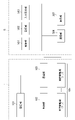
- FIG. 1 is an overall configuration diagram of a robot system 300 according to this embodiment. As is clear from the figure, in this embodiment, the dual-arm robot 1 is connected to the information processing device 5 by wire or wirelessly to form a robot system 300 .
- FIG. 2 is an explanatory diagram regarding joint arrangement of the dual-arm robot 1.
- FIG. As is clear from the figure, in the center of the figure, a trunk portion 11 extending vertically upward from the ground plane is arranged. A head portion 19 is connected to the upper end of the body portion 11 via a neck portion 18 .
- a right arm 12 is connected to the upper end of the right side of the body 11 , and a left arm 14 is connected to the upper end of the left side of the body 11 .
- the torso 11 has a first torso joint (T_J1) that rotates the upper part (upper body) of the torso 11 to the left and right, and a second torso joint (T_J1) that tilts the upper part of the torso 11 forward or backward. T_J2) is provided.
- the right arm 12 has 7 degrees of freedom. That is, the right arm first rotation joint (R_J1) that rotates the right arm 12 around an axis that extends horizontally from the root of the right arm 12 to the trunk 11, and from the vicinity of the center of the shoulder of the right arm 12
- the second right arm joint (R_J2) that rotates around the axis extending forward
- the third right arm joint that is located in the upper arm directly below the second right arm joint and rotates the elbow and below around the central axis in the longitudinal direction. (R_J3).
- the right arm 12 includes a right arm fourth joint (R_J4) that rotates the forearm around an axis that extends forward from the vicinity of the center of the elbow of the right arm 12, and a forearm directly below the right arm fourth joint.
- the right arm fifth joint (R_J5) that rotates the hand around the central axis in the longitudinal direction, and the right arm that rotates around the axis orthogonal to the longitudinal direction, which is located near the tip position from the right arm fifth joint. It has a sixth joint (R_J6) and a seventh joint (R_J7) that rotates about an axis extending forward from near the center of the hand.
- FIG. 3 is a functional block diagram of the robot system 300.
- the information processing device 5 includes a control section 501 , a storage section 502 , an input reception section 503 , a communication section 506 and a display section 507 .
- the control unit 501 is an arithmetic processing unit such as a CPU, and executes the loaded program.
- the storage unit 502 is a storage device such as ROM/RAM, hard disk, flash memory, etc., and stores programs and various data described later, such as joint information and setting information required for operation in each mode.
- the input reception unit 503 performs processing for receiving input from an operator, administrator, user, or the like.
- a communication unit 506 is a communication unit and performs communication with the dual-arm robot 1 .
- a display unit 507 performs processing for displaying image information on a display (not shown) or the like.
- the dual-arm robot 1 includes a storage unit 101, a control unit 102, a communication unit 103, and a plurality of joint drive units 105 (T_J1, T_J2, L_J1 to L_J7, R_J1 to R_J7) that drive the joints of the dual-arm robot 1. It has although not shown, each joint of the dual-arm robot 1 is provided with a sensor for acquiring various information such as the angle, angular velocity, angular acceleration, current value, and torque value of each joint. is provided to the control unit 102 .
- the storage unit 101 and the control unit 102 constitute a microcomputer, the storage unit 101 is a storage device such as ROM/RAM, and the control unit 102 is an arithmetic processing device such as a CPU.
- the communication unit 103 is a communication unit that exchanges information with the communication unit 506 of the information processing device 5 .
- Each joint driving unit 105 is controlled by the control unit 102 to drive each joint.
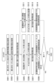
- FIG. 4 is a general flow chart for the operation of robotic system 300 .
- the control unit 501 executes a process of displaying a mode acceptance display via the display unit 507 (S1).
- This mode acceptance display includes a display for prompting the operator or the like to select one of the modes.
- the information processing device 5 enters a standby state until it receives a mode selection signal (or mode switching signal) input via the input reception unit 503 (S2 NO).
- each mode start operation is executed. That is, a process for starting the corresponding mode according to the detected mode selection signal is performed (S3).
- the control unit 501 executes the first mode start process (S5).
- the second mode start process is executed (S6).
- a third mode start process is executed (S7).
- fourth mode start processing is executed (S9). Each process described later is executed by these mode start processes.
- control unit 501 repeats the series of operations again (S1 to S9).
- FIG. 5 is a detailed flowchart regarding the first mode executed by the first mode start process (S5).
- the control unit 501 performs a process of reading joint information related to the first mode from the storage unit 502 (S501).
- Joint information is information indicating what kind of control is applied to which joint.
- This setting information includes hardware information of the dual-arm robot 1 such as link lengths of each part of the dual-arm robot 1 and link parameters (L) representing the relationship between links, information on the origin (O, O L ') and Information (TCP(L), TCP(R)) on the left and right TCPs (Tool Center Points), which are target points to be controlled, is included.
- the origin O is set at the central ground plane of the body 11 and TCP(R) is set near the tip of the right arm 12 .
- the origin O L ′ is set at the root of the left arm 14
- TCP(L) is set near the tip of the left arm 14 .
- the kinematic chain refers to a series of interlocking joints existing from the origin O to the TCP.
- This kinematic chain is specifically specified by specifying the joint variable vector (q) and the link parameter (L).
- FIG. 6 is a conceptual diagram of the kinematic chain according to the first mode.
- an arrow is shown from the origin O to TCP(R) via the trunk joint (T_J1 ⁇ T_J2), the right arm joint (R_J1 ⁇ R_J2 ⁇ ... ⁇ R_J7).
- a series of joints existing from the origin O to TCP(R) is specified as a kinematic chain used for interlocking control of the torso 11 and right arm 12 .
- the control unit 501 performs a current value acquisition process for each joint of the dual-arm robot 1 (S503).
- the current values related to joints are the current values of angles, angular velocities, angular accelerations, current values, torque values, etc. of each joint acquired by predetermined sensors provided in the dual-arm robot 1 .
- the control unit 501 After the Jacobian matrix calculation process, the control unit 501 performs a command value acquisition process for TCP(R) (S507).
- the command value is acquired by reading from the storage unit 502 .
- the command value is not limited to that shown in this embodiment, and for example, the command value may be generated according to information from various sensors such as a camera.
- the information processing device 5 and the dual-arm robot 1 work together to solve the inverse kinematics based on the command value in the Cartesian coordinate system for TCP(R) and the Jacobian matrix to obtain the torso Interlocking control processing of joints (T_J1, T_J2) and right arm joints (R_J1, R_J2, . . . , R_J7), for example, position control of each joint is performed (S508). After that, the process proceeds to the end determination process (S510).
- the control unit 501 performs calculation processing of a function related to forward kinematics for the kinematic chain from the origin O to TCP(L) for the left arm 14 (S511). That is, as is widely known to those skilled in the art, the nonlinear vector function f(q, L ) is calculated.
- the control unit 501 After the Jacobian matrix calculation process, the control unit 501 performs a command value acquisition process for the left arm joint (S513).
- the command value is acquired by reading from the storage unit 502 .
- the command value is not limited to that shown in this embodiment, and for example, the command value may be generated according to information from various sensors such as a camera.
- the information processing device 5 and the dual-arm robot 1 cooperate to perform desired position control based on the command values in the joint coordinate system for each joint. For example, control may be performed such that each joint of the left arm 14 is held.
- FIG. 7 is a detailed flowchart regarding the third mode executed by the third mode start process (S7).
- the control unit 501 performs current value acquisition processing for each joint (S703).
- the current values related to joints are the current values of angles, angular velocities, angular accelerations, current values, torque values, etc. of each joint acquired by predetermined sensors provided in the dual-arm robot 1 .
- the control unit 501 After the Jacobian matrix calculation process, the control unit 501 performs a command value acquisition process for TCP(R) and TCP(L) (S707).
- the command value is acquired by reading from the storage unit 502 .
- the command value is not limited to that shown in this embodiment, and for example, the command value may be generated according to information from various sensors such as a camera.
- the information processing device 5 and the dual-arm robot 1 cooperate to solve the inverse kinematics using the calculated Jacobian matrix J to obtain the right arm joints (R_J1 to R_J7) and the left arm joints (L_J1 to L_J7) and trunk joints (T_J1, T_J2) are interlocked and controlled (S708).
- a desired position command in the Cartesian coordinate system is issued to the TCP (R) associated with the right arm 12 and the TCP (L) associated with the left arm 14 to control each joint.
- position commands in the Cartesian coordinate system are issued to each TCP, but the present invention is not limited to such a configuration, and commands may be issued in other modes.
- commands may be issued in other modes.
- velocity commands, current commands, force commands, or moment commands may be made in the Cartesian coordinate system for each TCP.
- a point other than the TCP such as an arbitrary hand position, may be set as the target point.
- inverse kinematics calculation is performed for interlocking control, but the present invention is not limited to such a configuration. Therefore, for example, impedance control or the like may be performed without performing inverse kinematics calculations. Also, in the present embodiment, the Jacobian matrix is used, but the present invention is not limited to such a configuration, and control calculation may be performed without using the Jacobian matrix.
- the control processing (S703-S708) for each joint is repeatedly executed until a predetermined end signal is received (S709 NO). On the other hand, if a predetermined end signal has been received (S709YES), the process ends.
- the joints of the whole body can be linked and controlled, so the workability of the dual-arm robot 1 can be improved.
- FIG. 9 is a detailed flowchart regarding the fourth mode executed by the fourth mode start process (S9).
- the control unit 501 performs a process of reading joint information corresponding to the fourth mode from the storage unit 502 (S901). More specifically, in the fourth mode, a plurality of joint groups, that is, the right arm joints (R_J1 to R_J7) and the left arm joints (L_J1 to L_J7) are specified as target joint groups for interlock control. , the corresponding joint variable vector (q) is read. Also, for the trunk joints (T_J1, T_J2), the corresponding joint variable vector (q) is read assuming that desired position control or the like is performed in the joint coordinate system.
- This setting information includes hardware information of the dual-arm robot 1 such as link lengths of each part of the dual-arm robot 1 and link parameters (L) representing the relationship between links, etc.
- the origin O is arranged on the ground plane at the center of the trunk portion 11 .
- the origins O L ' and O R ' for the left and right arms are arranged near the roots of the left and right arms 12 and 14, respectively.
- left and right TCP(R) and TCP(L) are set near the tip of each arm 12 and 14 .
- the control unit 501 performs current value acquisition processing for each joint (S903).
- the current values related to joints are the current values of angles, angular velocities, angular accelerations, current values, torque values, etc. of each joint acquired by predetermined sensors provided in the dual-arm robot 1 .
- the control unit 501 After the joint current value acquisition process, the control unit 501 performs forward kinematic function calculation process for the trunk joints (T_J1, T_J2) (S904). That is, as is widely known to those skilled in the art, a nonlinear vector function that calculates the position and orientation of each origin O L ', O R ' from each joint angle based on the joint variable vector (q) and the link parameter (L) Calculate f(q, L).
- control for the right arm 12, control for the left arm 14, and control for the torso 11 are executed in parallel.
- the control unit 501 performs calculation processing of a function related to forward kinematics for the kinematic chain from the right arm origin O R ' to TCP(R) (S906). That is, based on the joint variable vector (q) and the link parameter (L), a nonlinear vector function f(q, L) for calculating the position and orientation of TCP(R) from each joint angle is calculated.
- the control unit 501 After the Jacobian matrix calculation process, the control unit 501 performs a command value acquisition process for TCP(R) (S908).
- the command value is acquired by reading from the storage unit 502 .
- the command value is not limited to that shown in this embodiment, and for example, the command value may be generated according to information from various sensors such as a camera.
- the information processing device 5 and the dual-arm robot 1 work together to solve inverse kinematics using the calculated Jacobian matrix J, thereby interlocking control of the right arm joints (R_J1 to R_J7). (S909). Specifically, a desired position command in the Cartesian coordinate system is issued to TCP(R) to perform interlocking control.
- a position command in the Cartesian coordinate system is issued to TCP(R), but the present invention is not limited to such a configuration, and commands may be issued in other modes. Therefore, for example, a speed command, current command, force command, or moment command may be given to TCP(R) in the Cartesian coordinate system. Also, a point other than TCP(R), for example, an arbitrary hand position or the like may be set as the target point.
- the interlocking control process for the right arm joint is repeatedly executed until a predetermined end signal is received (S910 NO). On the other hand, if a predetermined end signal has been received (S910YES), the process ends.
- a position command in the Cartesian coordinate system is given to TCP(L), but the present invention is not limited to such a configuration, and commands may be given in other modes. Therefore, for example, a speed command, current command, force command, or moment command in the Cartesian coordinate system may be given to TCP(L). Also, a point other than TCP(L), such as an arbitrary hand position, may be set as the target point.
- inverse kinematics calculation is performed for interlocking control, but the present invention is not limited to such a configuration. Therefore, for example, impedance control or the like may be performed without performing inverse kinematics calculations. Also, in the present embodiment, the Jacobian matrix is used, but the present invention is not limited to such a configuration, and control calculation may be performed without using the Jacobian matrix.
- the interlocking control process for the left arm joint is repeatedly executed until a predetermined end signal is received (S916 NO). On the other hand, if a predetermined end signal has been received (S916YES), the process ends.
- control unit 501 After the command value acquisition process, the control unit 501 performs desired position control for each joint (T_J1, T_J2) of the torso 11 based on the command value in the joint coordinate system (S922).
- FIG. 10 is a conceptual diagram of a kinematic chain according to the fourth mode.
- the kinematic chain according to the fourth mode first, from the origin O along the arrow, through the trunk joint (T_J1 ⁇ T_J2), the left and right arm origins O R ' at the bases of the left and right arms, A kinematic chain up to O L ' is identified.
- the TCP (R) of the right arm 12 After that, toward the TCP (R) of the right arm 12, along the arrow from the right arm origin O R ', through the right arm joints (R_J1 ⁇ R_J2 ⁇ ... ⁇ R_J7) in order, the TCP (R) of the right arm 12 ( A series of joints on the route to R) form a kinematic chain for interlocking control of the right arm 12 .
- the desired joints that is, the right arm joints (R_J1 to R_J7) and the left arm joints (L_J1 to L_J7), are controlled independently of the right arm 12, the left arm 14, and the torso 11. ), interlocking control can be applied. Thereby, the workability of the dual-arm robot 1 can be improved.
- TCP was adopted as the target point for commanding, but the present invention is not limited to such a configuration. Therefore, for example, a point other than the TCP may be used as the target point of the robot, or a virtual point outside the robot housing may be used as the target point for control.
- FIG. 11 is an explanatory diagram regarding commands to virtual points.
- the dual-arm robot 1 described in the first embodiment lifts a rectangular parallelepiped load 21 when it is in the third mode, that is, the whole-body interlocking mode.
- a virtual point that serves as a target point for commanding a position or the like is placed at the middle point (V) between the TCP (R) of the right arm 12 and the TCP (L) of the left arm 14 .
- Whole-body interlocking control can be performed by issuing a command to this intermediate point (V).
- a command for a virtual point when a command for a virtual point is detected, it is converted into a TCP (R) command for the right arm 12 and a TCP (L) command for the left arm 14 . Since subsequent processing is the same as that shown in the first embodiment, detailed description is omitted.
- the dual-arm robot 1 has been described as being in the third mode, but it may be executed in another mode.
- the first to fourth modes are freely switched without any timing restrictions (see FIG. 1), but the present invention is not limited to such a configuration. Therefore, for example, a detection unit is provided to detect whether or not the robot is in motion from information obtained by various sensors provided in the robot. or a warning processing unit that visually or audibly warns the operator or the like.
- switching is performed based on an input to the input reception unit 503, but the present invention is not limited to such a configuration. Therefore, in addition to the input signal from the input reception unit 503, the mode may be automatically switched according to a command from a host system, an external system, or the like, or a predetermined condition determination. Further, instead of directly switching modes, switching may be suggested visually or aurally.
- the information processing device 5 performs the first to second movements accompanied by the interlocking of the torso 11.
- a visual or audible warning may be provided to alert the user to switch to mode 3. Further, along with the warning or independently, the switching process to any one of the first to third modes involving the interlocking of the torso 11 may be performed.
- the unit of control is the torso 11, the right arm 12, or the left arm 14, but the configuration is not limited to this. Therefore, for example, a control unit may be assigned across each part, or a control unit may be assigned to a partial joint group of each part.
- the present invention can be used in industries that manufacture robots and the like.
Landscapes
- Engineering & Computer Science (AREA)
- Robotics (AREA)
- Mechanical Engineering (AREA)
- Manipulator (AREA)
Abstract
L'invention concerne un robot comprenant une pluralité d'articulations, le robot étant pourvu : d'une unité de réglage pour régler une partie ou la totalité de la pluralité d'articulations en tant qu'articulations cibles pour une commande coordonnée, en fonction d'un signal de commutation ; et d'une unité de commande pour effectuer une commande coordonnée des articulations cibles.
Priority Applications (1)
| Application Number | Priority Date | Filing Date | Title |
|---|---|---|---|
| PCT/JP2021/033565 WO2023037550A1 (fr) | 2021-09-13 | 2021-09-13 | Robot, système de robot, procédé de commande et programme |
Applications Claiming Priority (1)
| Application Number | Priority Date | Filing Date | Title |
|---|---|---|---|
| PCT/JP2021/033565 WO2023037550A1 (fr) | 2021-09-13 | 2021-09-13 | Robot, système de robot, procédé de commande et programme |
Publications (1)
| Publication Number | Publication Date |
|---|---|
| WO2023037550A1 true WO2023037550A1 (fr) | 2023-03-16 |
Family
ID=85506251
Family Applications (1)
| Application Number | Title | Priority Date | Filing Date |
|---|---|---|---|
| PCT/JP2021/033565 WO2023037550A1 (fr) | 2021-09-13 | 2021-09-13 | Robot, système de robot, procédé de commande et programme |
Country Status (1)
| Country | Link |
|---|---|
| WO (1) | WO2023037550A1 (fr) |
Citations (7)
| Publication number | Priority date | Publication date | Assignee | Title |
|---|---|---|---|---|
| DE3932013A1 (de) * | 1988-11-23 | 1990-05-31 | Berlin Oberbekleidung | Zweiarmiger industrieroboter |
| JPH07256580A (ja) * | 1994-03-18 | 1995-10-09 | Fujitsu Ltd | 複腕協調制御装置 |
| JPH08328626A (ja) * | 1995-05-30 | 1996-12-13 | Nec Corp | 複腕ロボット制御装置 |
| JP2008502488A (ja) * | 2004-06-15 | 2008-01-31 | エービービー エービー | 複数の相互作用ロボットをオフラインでプログラミングする方法及びシステム |
| JP2010029987A (ja) * | 2008-07-29 | 2010-02-12 | Yaskawa Electric Corp | ハンドリングシステムおよびハンドリング方法 |
| JP2015174184A (ja) * | 2014-03-14 | 2015-10-05 | 三菱重工業株式会社 | 制御装置 |
| WO2019142583A1 (fr) * | 2018-01-19 | 2019-07-25 | ソニー株式会社 | Dispositif de robot, et procédé de fabrication d'un appareil électronique |
-
2021
- 2021-09-13 WO PCT/JP2021/033565 patent/WO2023037550A1/fr active Application Filing
Patent Citations (7)
| Publication number | Priority date | Publication date | Assignee | Title |
|---|---|---|---|---|
| DE3932013A1 (de) * | 1988-11-23 | 1990-05-31 | Berlin Oberbekleidung | Zweiarmiger industrieroboter |
| JPH07256580A (ja) * | 1994-03-18 | 1995-10-09 | Fujitsu Ltd | 複腕協調制御装置 |
| JPH08328626A (ja) * | 1995-05-30 | 1996-12-13 | Nec Corp | 複腕ロボット制御装置 |
| JP2008502488A (ja) * | 2004-06-15 | 2008-01-31 | エービービー エービー | 複数の相互作用ロボットをオフラインでプログラミングする方法及びシステム |
| JP2010029987A (ja) * | 2008-07-29 | 2010-02-12 | Yaskawa Electric Corp | ハンドリングシステムおよびハンドリング方法 |
| JP2015174184A (ja) * | 2014-03-14 | 2015-10-05 | 三菱重工業株式会社 | 制御装置 |
| WO2019142583A1 (fr) * | 2018-01-19 | 2019-07-25 | ソニー株式会社 | Dispositif de robot, et procédé de fabrication d'un appareil électronique |
Similar Documents
| Publication | Publication Date | Title |
|---|---|---|
| US11103322B2 (en) | Remote control robot system | |
| EP2699392B1 (fr) | Robot industriel doté d'un bras redondant en cinématique et procédé de commande du robot | |
| KR101581096B1 (ko) | 다관절형 로봇의 제어 장치, 제어 방법 및 제어 프로그램을 기록한 컴퓨터 판독가능한 기록 매체 | |
| Okamura et al. | An overview of dexterous manipulation | |
| JP6570742B2 (ja) | ロボット動作評価装置、ロボット動作評価方法及びロボットシステム | |
| US9044856B2 (en) | Robot apparatus, method of controlling the same, and computer program | |
| US8977392B2 (en) | Robot control device, robot control method, robot control program, and robot system | |
| CN109620410A (zh) | 机械臂防碰撞的方法及系统、医疗机器人 | |
| US20160346921A1 (en) | Portable apparatus for controlling robot and method thereof | |
| CN102470530A (zh) | 生成机器人的教导数据的方法以及机器人教导系统 | |
| CN111319039B (zh) | 机器人 | |
| CN111712356A (zh) | 机器人系统和操作方法 | |
| CN111283688B (zh) | 机器人的避障方法及机器人设备 | |
| US11613012B2 (en) | Robot controller | |
| US10507585B2 (en) | Robot system that displays speed | |
| CN114603533B (zh) | 存储介质及机器人的示教方法 | |
| CN111093911A (zh) | 机器人系统及其运行方法 | |
| CN107498557A (zh) | 一种机器人的控制方法及系统 | |
| WO2023037550A1 (fr) | Robot, système de robot, procédé de commande et programme | |
| KR102422355B1 (ko) | 증강현실 기반의 수중로봇 원격제어 시스템 | |
| US20220009101A1 (en) | Control device, control method, and non-transitory recording medium | |
| JP2010247309A (ja) | ロボットアーム、及びその制御方法 | |
| CN114378809A (zh) | 软体机器人操纵器的无奇点运动学参数化 | |
| JP2009045678A (ja) | ロボットの作業成否判定方法およびロボットシステム | |
| KR102225348B1 (ko) | 로봇 자세 정의를 위한 기준점 기반의 좌표계 특정 시스템 및 방법 |
Legal Events
| Date | Code | Title | Description |
|---|---|---|---|
| 121 | Ep: the epo has been informed by wipo that ep was designated in this application |
Ref document number: 21956845 Country of ref document: EP Kind code of ref document: A1 |
|
| WWE | Wipo information: entry into national phase |
Ref document number: 2023546717 Country of ref document: JP |