WO2023033045A1 - バルーンカテーテル - Google Patents
バルーンカテーテル Download PDFInfo
- Publication number
- WO2023033045A1 WO2023033045A1 PCT/JP2022/032770 JP2022032770W WO2023033045A1 WO 2023033045 A1 WO2023033045 A1 WO 2023033045A1 JP 2022032770 W JP2022032770 W JP 2022032770W WO 2023033045 A1 WO2023033045 A1 WO 2023033045A1
- Authority
- WO
- WIPO (PCT)
- Prior art keywords
- balloon
- cylinder shaft
- layer
- fixing member
- balloon catheter
- Prior art date
- Legal status (The legal status is an assumption and is not a legal conclusion. Google has not performed a legal analysis and makes no representation as to the accuracy of the status listed.)
- Ceased
Links
Images


Classifications
-
- A—HUMAN NECESSITIES
- A61—MEDICAL OR VETERINARY SCIENCE; HYGIENE
- A61F—FILTERS IMPLANTABLE INTO BLOOD VESSELS; PROSTHESES; DEVICES PROVIDING PATENCY TO, OR PREVENTING COLLAPSING OF, TUBULAR STRUCTURES OF THE BODY, e.g. STENTS; ORTHOPAEDIC, NURSING OR CONTRACEPTIVE DEVICES; FOMENTATION; TREATMENT OR PROTECTION OF EYES OR EARS; BANDAGES, DRESSINGS OR ABSORBENT PADS; FIRST-AID KITS
- A61F2/00—Filters implantable into blood vessels; Prostheses, i.e. artificial substitutes or replacements for parts of the body; Appliances for connecting them with the body; Devices providing patency to, or preventing collapsing of, tubular structures of the body, e.g. stents
- A61F2/95—Instruments specially adapted for placement or removal of stents or stent-grafts
- A61F2/958—Inflatable balloons for placing stents or stent-grafts
-
- A—HUMAN NECESSITIES
- A61—MEDICAL OR VETERINARY SCIENCE; HYGIENE
- A61B—DIAGNOSIS; SURGERY; IDENTIFICATION
- A61B17/00—Surgical instruments, devices or methods
- A61B17/22—Implements for squeezing-off ulcers or the like on inner organs of the body; Implements for scraping-out cavities of body organs, e.g. bones; for invasive removal or destruction of calculus using mechanical vibrations; for removing obstructions in blood vessels, not otherwise provided for
-
- A—HUMAN NECESSITIES
- A61—MEDICAL OR VETERINARY SCIENCE; HYGIENE
- A61M—DEVICES FOR INTRODUCING MEDIA INTO, OR ONTO, THE BODY; DEVICES FOR TRANSDUCING BODY MEDIA OR FOR TAKING MEDIA FROM THE BODY; DEVICES FOR PRODUCING OR ENDING SLEEP OR STUPOR
- A61M25/00—Catheters; Hollow probes
- A61M25/0043—Catheters; Hollow probes characterised by structural features
- A61M25/005—Catheters; Hollow probes characterised by structural features with embedded materials for reinforcement, e.g. wires, coils, braids
-
- A—HUMAN NECESSITIES
- A61—MEDICAL OR VETERINARY SCIENCE; HYGIENE
- A61M—DEVICES FOR INTRODUCING MEDIA INTO, OR ONTO, THE BODY; DEVICES FOR TRANSDUCING BODY MEDIA OR FOR TAKING MEDIA FROM THE BODY; DEVICES FOR PRODUCING OR ENDING SLEEP OR STUPOR
- A61M25/00—Catheters; Hollow probes
- A61M25/10—Balloon catheters
- A61M25/104—Balloon catheters used for angioplasty
-
- A—HUMAN NECESSITIES
- A61—MEDICAL OR VETERINARY SCIENCE; HYGIENE
- A61B—DIAGNOSIS; SURGERY; IDENTIFICATION
- A61B17/00—Surgical instruments, devices or methods
- A61B2017/00743—Type of operation; Specification of treatment sites
- A61B2017/00778—Operations on blood vessels
- A61B2017/00783—Valvuloplasty
-
- A—HUMAN NECESSITIES
- A61—MEDICAL OR VETERINARY SCIENCE; HYGIENE
- A61B—DIAGNOSIS; SURGERY; IDENTIFICATION
- A61B17/00—Surgical instruments, devices or methods
- A61B17/22—Implements for squeezing-off ulcers or the like on inner organs of the body; Implements for scraping-out cavities of body organs, e.g. bones; for invasive removal or destruction of calculus using mechanical vibrations; for removing obstructions in blood vessels, not otherwise provided for
- A61B2017/22001—Angioplasty, e.g. PCTA
-
- A—HUMAN NECESSITIES
- A61—MEDICAL OR VETERINARY SCIENCE; HYGIENE
- A61B—DIAGNOSIS; SURGERY; IDENTIFICATION
- A61B17/00—Surgical instruments, devices or methods
- A61B17/22—Implements for squeezing-off ulcers or the like on inner organs of the body; Implements for scraping-out cavities of body organs, e.g. bones; for invasive removal or destruction of calculus using mechanical vibrations; for removing obstructions in blood vessels, not otherwise provided for
- A61B2017/22051—Implements for squeezing-off ulcers or the like on inner organs of the body; Implements for scraping-out cavities of body organs, e.g. bones; for invasive removal or destruction of calculus using mechanical vibrations; for removing obstructions in blood vessels, not otherwise provided for with an inflatable part, e.g. balloon, for positioning, blocking, or immobilisation
-
- A—HUMAN NECESSITIES
- A61—MEDICAL OR VETERINARY SCIENCE; HYGIENE
- A61B—DIAGNOSIS; SURGERY; IDENTIFICATION
- A61B17/00—Surgical instruments, devices or methods
- A61B17/22—Implements for squeezing-off ulcers or the like on inner organs of the body; Implements for scraping-out cavities of body organs, e.g. bones; for invasive removal or destruction of calculus using mechanical vibrations; for removing obstructions in blood vessels, not otherwise provided for
- A61B2017/22098—Decalcification of valves
-
- A—HUMAN NECESSITIES
- A61—MEDICAL OR VETERINARY SCIENCE; HYGIENE
- A61M—DEVICES FOR INTRODUCING MEDIA INTO, OR ONTO, THE BODY; DEVICES FOR TRANSDUCING BODY MEDIA OR FOR TAKING MEDIA FROM THE BODY; DEVICES FOR PRODUCING OR ENDING SLEEP OR STUPOR
- A61M25/00—Catheters; Hollow probes
- A61M25/10—Balloon catheters
- A61M2025/1043—Balloon catheters with special features or adapted for special applications
- A61M2025/1075—Balloon catheters with special features or adapted for special applications having a balloon composed of several layers, e.g. by coating or embedding
-
- A—HUMAN NECESSITIES
- A61—MEDICAL OR VETERINARY SCIENCE; HYGIENE
- A61M—DEVICES FOR INTRODUCING MEDIA INTO, OR ONTO, THE BODY; DEVICES FOR TRANSDUCING BODY MEDIA OR FOR TAKING MEDIA FROM THE BODY; DEVICES FOR PRODUCING OR ENDING SLEEP OR STUPOR
- A61M2210/00—Anatomical parts of the body
- A61M2210/12—Blood circulatory system
Definitions
- the present invention relates to balloon catheters used in the medical field.
- Medical balloon catheters generally have a shaft and a balloon formed at its tip, and by expanding the balloon, treatment is performed in a minimally invasive manner.
- Specific therapeutic applications include therapeutic modalities such as arrhythmia treatment, embolic removal, angioplasty and balloon aortic valvuloplasty.
- angioplasty and balloon aortic valvuloplasty use the balloon of the balloon catheter itself to dilate the stenosed body lumen, or after delivering an expandable endoprosthesis such as a stent into the body lumen. , can be used to expand the balloon and deploy the endoprosthesis.
- valve orifice area may become narrower when a new transcatheter artificial valve is placed. Therefore, in order to widen the valve orifice area, treatment can be performed to crush the surgically implanted artificial valve frame by dilation using a balloon catheter.
- the expansion pressure required varies depending on the treatment method.
- the expansion pressure required for the balloon to be left in place is required to be 7 atm or more.
- expansion pressures of 15 atm or more are required to fracture surgically implanted prosthetic valve frames.
- a balloon with two layers, an inner layer and an outer layer is used to achieve both flexibility that can follow the bending of the body lumen and sufficient strength to expand it.
- a balloon catheter has been reported in which a tubular net-like reinforcing member is arranged between the inner layer and the outer layer, the reinforcing member is fixed only at the ends of the inner layer and the outer layer, and the intermediate portion is not directly fixed (Patent Document 1). .
- Non-Patent Document 1 a technique of crushing an artificial valve by using a balloon with improved pressure resistance by spirally providing high-strength fibers inside has been reported.
- JP 2016-052447 A Japanese Patent Application Laid-Open No. 2020-062399 Japanese Patent Application Laid-Open No. 2021-013743
- a cylindrical net-like member having a tensile strength at break of 2 GPa or more and an elastic modulus of 50 GPa or more constituting an intermediate layer between the inner layer and the outer layer of the balloon. strength fibers, etc.), but if you want to expand the balloon at the target position, since the inner layer, the middle layer, and the outer layer of the balloon are integrated, when the balloon is expanded at the target position, There is a problem that the balloon is swept away by the blood stream and displaced. Furthermore, since the position is shifted during expansion, it is necessary to expand the balloon several times in order to position the balloon, and blood flow is stopped each time.
- Non-Patent Document 1 also has the problem that if the balloon is expanded at the target position, it will be washed away by the blood flow and the position will be displaced. Furthermore, since the balloon is displaced from the desired position during expansion, the balloon must be expanded multiple times, which can lead to incorrect expansion of the artificial valve cusps and left ventricular outflow tract, resulting in artificial valve dysfunction and atrioventricular block. There is a problem that it causes symptoms such as.
- the intravascular device of Patent Document 3 has a structure in which the stent retriever and the shaft can be separated, so there is a problem that it is difficult to use in procedures that require high pressure. Also, since the stentreaver is self-expanding, it must be used in combination with a member such as a microcatheter for intravascular delivery.
- an object of the present invention is to provide a balloon catheter that can independently fix a balloon securely at a target position without interrupting blood flow.
- a fixing member that expands or contracts in diameter in a lateral direction, the tip of the inner cylinder shaft and the tip of the fixing member are fixed to each other, and the tip of the outer cylinder shaft and the rear of the fixing member are fixed to each other;
- a balloon catheter wherein the ends are fixed to each other and the fixing member has a gap through which an external fluid can pass when expanded.
- the fixing member is made of a wire, and the wire has a braided shape, a woven shape, a helical shape, or a linear shape.
- the wire has a Young's modulus of 60 to 500 GPa and a tensile strength of 500 MPa or more.
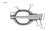
- the inner cylinder shaft has a large diameter portion provided at the distal end of the inner cylinder shaft and a small diameter portion provided at the proximal end of the inner cylinder shaft and having an inner diameter smaller than that of the large diameter portion. and wherein the balloon is fixed to the small diameter portion of the inner cylinder shaft, and the fixing member is directly fixed to the large diameter portion of the inner cylinder shaft. Balloon catheter as described.
- the wire has a cross-sectional area of 0.0019 mm 2 or more, and the balloon consists of one or more layers including a layer of an elastic material, and is for treatment of aortic valve stenosis.
- the balloon catheter according to any one of (6) The wire rod has a cross-sectional area of 0.0038 mm 2 or more, and the balloon consists of two or more layers including an elastic material layer and a resin fiber braided layer, and is for expanding a stent.
- the wire rod has a cross-sectional area of 0.0063 mm 2 or more, and the balloon consists of three or more layers including an elastic material layer and a braided layer of resin fibers, and is for crushing an artificial valve.
- the fixing member having a gap is arranged outside the balloon so as not to block external fluid such as blood flow, which will be described later.
- external fluid such as blood flow
- the cylindrical shaft By moving the cylindrical shaft in the longitudinal direction, it is possible to expand the diameter of only the fixing member and fix it in the lumen without blocking external fluid, and then expand the balloon for treatment, thereby suppressing the effects of blood flow blockage. , balloon misalignment can be reduced.
- the fixing member is hard, it is possible to perform a wide range of surgical techniques, such as artificial valve rupture, which has been difficult in the past, which requires high pressure resistance, and aortic valve dilatation, which requires low pressure resistance.
- FIG. 4 is a cross-sectional view of the balloon catheter according to the first embodiment of the present invention when the diameter of the fixing member is expanded and the balloon is inflated.
- FIG. 4 is a cross-sectional view when the diameter of the fixing member according to the first embodiment of the present invention is reduced and the balloon is deflated.
- FIG. 4 is a cross-sectional view when the diameter of the fixing member according to the first embodiment of the present invention is expanded and the balloon is contracted; It is a figure which shows an example of the treatment method using the 1st Embodiment of this invention.
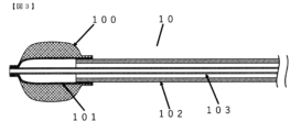
- FIG. 4 is a cross-sectional view of the vicinity of a balloon of a balloon catheter according to a second embodiment of the present invention; FIG.
- FIG. 8 is a cross-sectional view of the vicinity of a balloon of a balloon catheter according to a third embodiment of the present invention
- FIG. 11 is a cross-sectional view of the vicinity of a balloon of a balloon catheter according to a fourth embodiment of the present invention
- the balloon catheter of the present invention includes a flexible outer cylinder shaft, a flexible inner cylinder shaft inserted through the outer cylinder shaft, a flexible inner cylinder shaft fixed to the outer cylinder shaft, and a space inside the outer cylinder shaft. and a balloon that expands or contracts in the lateral direction due to the pressure of the internal fluid supplied through the balloon, and is arranged on the outer peripheral side of the balloon, and the balloon is arranged by the mutual movement in the longitudinal direction of the outer cylinder shaft and the inner cylinder shaft.
- distal end means the end in the longitudinal direction of the member shown in the specification when the operator perceives the balloon catheter
- proximal end means the end of the balloon catheter from the operator.
- catheter it is meant the proximal longitudinal end of the member indicated in the specification of the balloon catheter.
- fixed means that two members are fixed, and unless there is a particular limitation, they may be fixed via another member.
- Internal fluid means a fluid that flows inside the balloon, and examples thereof include liquids such as water and physiological saline, and gases such as nitrogen gas.
- the term “external fluid” means a fluid that flows outside the balloon, and includes, for example, blood that flows outside the balloon when a catheter enters a blood vessel during balloon catheterization.
- the “expansion pressure” means the internal pressure generated in the lumen of the balloon when the internal fluid is injected into the balloon.
- “Inelastic material” means a material with low elastic force, that is, a material with an elastic modulus (Young's modulus) at room temperature (test method: ISO6892-1) of about 10 GPa or more.
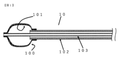
- FIG. 1 is a cross-sectional view of the balloon catheter 10 according to the first embodiment of the present invention when the diameter of the fixing member is expanded and the balloon is inflated.
- a balloon catheter 10 shown in FIG. 1 is a cross-sectional view of the balloon catheter 10 according to the first embodiment of the present invention when the diameter of the fixing member is expanded and the balloon is inflated.
- a balloon catheter 10 shown in FIG. 1 is a cross-sectional view of the balloon catheter 10 according to the first embodiment of the present invention when the diameter of the fixing member is expanded and the balloon is inflated.
- the fixing member 100 in the balloon catheter 10 has the distal end portion of the inner cylindrical shaft 103 and the distal end portion of the fixing member 100 fixed to each other, and the distal end portion of the outer cylindrical shaft 102 and the rear end portion of the fixing member 100 are fixed to each other. They are fixed to each other and arranged on the outer peripheral side of the balloon 101 . Therefore, due to mutual movement in the longitudinal direction of the outer cylindrical shaft 102 and the inner cylindrical shaft 103, the diameter of the fixing member 100 shown in FIG.
- the structure of the balloon catheter 10 changes as shown in the cross-sectional views when the member 100 expands in diameter and when the balloon 101 contracts, and is fixed in the lateral direction independently of the balloon 101 without using internal fluid.
- the member 100 can be expanded or contracted.
- the balloon catheter 10 itself can be fixed in the body cavity simply by moving the inner cylinder shaft 103 at the target position in the body cavity.
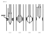
- treatment of a stenosis occurring in a body cavity with the balloon catheter 10 is performed by the procedures (procedures (1) to (4)) of the treatment method using the balloon catheter according to the first embodiment shown in FIG. can do.
- the fixing member 100 has a gap through which an external fluid can pass when the diameter is expanded, the balloon catheter 10 itself can be secured without blocking the external fluid flowing into the body cavity even when the diameter is expanded. It can be fixed in a body cavity.
- the fixing member 100 should have high rigidity and have a gap that does not block the external fluid, but is preferably made of wire.
- a braid is formed by braiding by tying or intertwining wire rods such as resin fibers and metal wires with a straight structure and braiding them in a wrong way (crossing them alternately).
- a woven shape formed by weaving materials such as linearly structured fibers and metal wires, a helical shape formed by spirally winding single or multiple fiber materials, and a single or multiple fiber materials in the axial direction of the balloon 101. It is preferable to have any one of linear shapes arranged in parallel to each other, and it may be a combination shape combining any of these shapes.
- the braided shape and the woven shape can be obtained, for example, by braiding, knitting, or weaving a plurality of wire rods of inelastic material.
- braiding broadly means to combine wire rods to retain their shape, and braiding means to tie wire rods together or intertwine them to braid them in a wrong way (intersect each other).
- it means the process of making a cloth-like structure.
- weaving means a process of making a cloth-like structure (woven structure) by crossing wire rods to be warp yarns and wire rods to be weft yarns under a certain rule.
- the size of the gap is preferably 0.002 mm 2 or more.
- the material of the fixing member 100 is not particularly limited, but preferably has a Young's modulus (test method: ISO6892-1) of 60 GPa to 500 GPa and a tensile strength of 500 MPa or more. More preferably, it is up to 500 GPa and has a tensile strength of 500 MPa or more.
- the cross-sectional area is preferably 0.0019 mm 2 or more, and preferably 0.0063 mm 2 or less.
- it is preferably made of an X-ray opaque material. For example, carbon or metal approved for medical use can be used.
- Metals such as aluminum, titanium, vanadium, chromium, manganese, iron, cobalt, nickel, copper, niobium, molybdenum, rhodium, palladium, tantalum, tungsten, rhenium, platinum and gold, and stainless steel and alloys containing two or more kinds of metals such as From the viewpoint of workability and economy, it is preferable to use stainless steel, and from the viewpoint of Young's modulus, it is preferable to use tungsten or a cobalt-chromium alloy (cobalt-chromium-molybdenum, etc.), and from the viewpoint of shape memory. Nickel titanium is preferred from.
- the fixing member 100 is not particularly limited as long as it achieves the expansion pressure necessary for the treatment method.
- the cross-sectional area is preferably 0.0019 mm 2 or more, and in the case of stent placement, the required expansion pressure is 7 atm or more.
- a cross-sectional area of 0.0063 mm 2 or greater is preferred because the expansion pressure is 15 atm or greater.
- the cross-sectional shape of the fixing member 100 is not particularly limited, a circular shape is preferable from the viewpoint of workability, and a rectangular shape is preferable from the viewpoint of ease of bending and friction of the fixing member.
- the balloon 101 has a structure capable of being expanded or contracted in the lateral direction by the pressure of internal fluid supplied through the space inside the outer cylinder shaft 102, which will be described later.
- the structure of the balloon 101 is composed of one or more layers, as shown in the cross-sectional view of the balloon catheter of the first embodiment shown in FIG. 1 and the cross-sectional view of the balloon catheter of the second embodiment shown in FIG. preferably formed.
- the balloon 101 When the balloon 101 has one layer, it is preferably made of only the elastic material 107 layer. In the case of multiple layers, it is preferable that the surface layer forming the outer surface and the inner layer forming the inner surface consist of layers of the elastic material 107 .
- the elastic material 107 is not particularly limited as long as it is a general rubber elastic material. As the rubber elastic material, for example, those having a hardness of 15 to 80 in JIS-A are preferable.
- Specific examples include natural rubber (latex), silicone elastomer, thermoplastic elastomer, isobutylene or polybutadiene rubber, polytetrafluoroethylene, fluorosilicone rubber, chlorinated polyethylene elastomer, ethylene vinyl acetate, hexafluoropropylene-vinylidene fluoride. - tetrafluoroethylene copolymers (e.g. trade names Fluorel® and Viton®), butyl rubber, synthetic polyisoprene rubber, styrene-butadiene rubber, tetrafluoroethylene propylene copolymers, thermoplastic copolyesters, Polyurethane etc. are mentioned.
- different materials may be selected for each portion of the balloon wall surface or for each layer of the balloon, or two or more types of materials may be mixed and the modulus of elasticity may be adjusted according to the intended use.
- Natural rubber (latex) is preferably used from the viewpoint of workability and economy, and polyurethane is preferably used from the viewpoint of pressure resistance and economy.
- natural rubber means naturally occurring rubber, and is usually obtained as natural rubber latex, which is an emulsion in which natural rubber particles are dispersed in a medium such as water.
- a braided layer 106 made of resin fibers is used as a surface layer of the balloon 101 when the balloon 101 has two layers, or as an intermediate layer inside the balloon 101 when the balloon 101 has three or more layers, as long as it does not impair the effects of the present invention.
- the material of the resin fiber is not particularly limited, but any material commonly used for resin fibers may be used, for example, polyurethane, polyolefin such as polyethylene or polypropylene, polyethylene terephthalate, polybutylene terephthalate, polyethylene-2, Polyester such as 6-naphthalate, polyamide such as nylon 6 and nylon 12, polyvinyl chloride, ethylene-vinyl acetate copolymer or saponified product thereof, polystyrene, polycarbonate, polysulfone, polyphenylene oxide, polyphenylene sulfide, aromatic polyamide, polyimide, polyamide Examples include imide, cellulose, cellulose acetate, polyvinylidene chloride, polyacrylonitrile, polyvinyl alcohol, and copolymers thereof.
- polyester and polyurethane are preferably used from the viewpoint of biocompatibility, elastic modulus, and the like.
- the cross-sectional shape of the resin fiber is not particularly limited, and various cross-sectional shapes can be appropriately selected according to the application and required properties. Specifically, it may have a perfect circular cross section or a non-perfect circular cross section. Specific examples of non-circular cross sections include multilobed, polygonal, flattened, elliptical, C-shaped, H-shaped, S-shaped, T-shaped, W-shaped, X-shaped, Y-shaped, square-shaped, cross-shaped and hollow Examples include, but are not limited to, shapes. Also, a plurality of types of cross-sectional shapes may be employed.
- the weight ratio of the resin fibers of the core yarn and the resin fibers of the sheath yarn is not particularly limited.
- the degree of entanglement of the composite false twisted yarn is not particularly limited, it is preferably 50-150. When the entanglement degree is 50 or more, separation of the core yarn and the sheath yarn is suppressed. Further, when it is 150 or less, it is preferable because there is no decrease in the elastic recovery rate.
- the knitting method of the braided layer 106 may be warp knitting, weft knitting, or flat knitting, as long as it is a method of knitting so as to have stretchability and pressure resistance. Weft knitting is preferred.
- the method of joining the braided layer 106 and the elastic material 107 is not particularly limited, but lamination using an adhesive, thermocompression bonding, kneading, extrusion molding, resin impregnation, coating, etc. can be used.
- the braided layer 106 formed by weaving false twist yarns made of polyurethane and polyester into a cylindrical shape and natural rubber may be adhered with a rubber glue to obtain a balloon.
- additives may be contained in an amount of 30% by mass or less with respect to 100% by mass of the elastic material 107 as long as the effects of the present invention are not impaired.
- X-ray contrast agents, coloring agents, antioxidants, heat stabilizers, lubricants and the like can be used as the various additives.
- the lower limit of the content of the additive is not particularly limited, and there is no problem even if it is 0% by mass with respect to 100% by mass of the elastic material.
- inorganic or organic particles may be contained in an amount of 20% by mass or less with respect to 100% by mass of the elastic material 107 as long as the performance of the present invention is not impaired.
- Examples thereof include calcium carbonate, titanium oxide, silicon oxide, calcium fluoride, lithium fluoride, alumina, barium sulfate, zirconia, calcium phosphate, crosslinked polystyrene particles and metal nanoparticles.
- the lower limit of the content of inorganic or organic particles is not particularly limited, and there is no problem even if it is 0% by mass with respect to 100% by mass of the elastic material 107 .
- the balloon 101 is not particularly limited as long as it achieves the expansion pressure required for the treatment method, but for example, when used for treatment of aortic valve stenosis, the expansion pressure required is 2 to 3 atm or more. Therefore, a balloon consisting of one or more layers including a layer of elastic material 107 is preferred, and in the case of stenting applications, since the expansion pressure required is 7 atm or more, the inner layer contains a layer of elastic material 107 and the surface layer 106 includes a braided layer 2 .
- a balloon composed of more than one layer is preferable, and in the case of artificial valve crushing applications, the required expansion pressure is 15 atm or more, so the surface layer is a layer of elastic material 107, the intermediate layer is a braided layer 106 of resin fibers, and the inner layer is a layer of elastic material 107.
- An inner cylinder shaft 103 is inserted into the lumen of the outer cylinder shaft 102, and a guide wire is passed through the lumen of the inner cylinder shaft 103. Along the guide wire, the inner cylinder shaft 103 and the outer cylinder shaft 102 is delivered into the body.
- the outer cylindrical shaft 102 may be of any flexible tubular shape, and may be formed of, for example, a one-layer tube or a multi-layer tube having two or more layers. It is preferably formed from a multi-layer tube consisting of three layers.
- the material used for the outer cylinder shaft 102 is preferably made of a polymer material having excellent antithrombotic properties because it comes into contact with living tissue.
- a polymer material having excellent antithrombotic properties examples include vinyl, polyurethane, polyamide, polyether block amide copolymer, polypropylene, polyolefin or polyethylene terephthalate.
- Polyurethane or polyether block amide copolymer suitable for the material of the balloon 101 is used to enable heat welding with the balloon. It is preferably coalesced.
- the outer layer of the outer cylinder shaft 102 is preferably made of a polymeric material having excellent antithrombotic properties because it comes into contact with living tissue.
- the polymer material include vinyl chloride, polyurethane, polyamide, polyether block amide copolymer, polypropylene, polyolefin, and polyethylene terephthalate. It is preferably a polyurethane or polyether block amide copolymer adapted to the
- the intermediate layer of the outer cylindrical shaft 102 preferably contains a metal rectangular wire or the like because durability and stiffness are required.
- the metal it is preferable to use, for example, stainless steel which is generally used for medical equipment.
- the inner layer of the outer cylindrical shaft 102 is required to be slippery, and the tube as a whole is preferably made of a polymeric material having stretch resistance.
- the polymer material it is preferable to use a fluorine-based polymer such as PTFE or a barium-containing polyether block amide copolymer.
- a polyether block amide copolymer containing barium it is preferable to use a polyether block amide copolymer containing barium.
- the materials used to satisfy the properties required for the outer layer, the inner layer, and the whole are not particularly limited, and can be lamination using an adhesive, thermocompression bonding, multilayer molding by co-extrusion, and kneading. And extrusion molding, resin impregnation, surface coating and the like can be used to obtain multilayer tubes.
- the inner cylinder shaft 103 may also be of any flexible tubular shape, and may be formed of, for example, a one-layer tube or a multi-layer tube having two or more layers. From the viewpoint of preventing the guide wire from buckling inside the inner tube shaft 103, it is preferable to adjust the bending rigidity according to the intended use, such as using a two-layer tube in which a hard material and a soft material are laminated.
- the polymeric material may be polyamide, polyether block amide, polyimide, polyetheretherketone, polyphenylene sulfide, polyetherimide or polyamideimide.
- Examples include, but are not particularly limited to.
- Polyamide or polyether block amide is preferred from the viewpoint of flexibility, and polyetheretherketone is more preferred from the viewpoint of rigidity.
- the mechanical properties (test method: ISO527) of the inner cylinder shaft 103 preferably have a tensile modulus of 500 to 1400 MPa and a yield strength of 25 MPa or more. If the tensile elastic modulus is 500 MPa or more, the inner cylinder shaft 103 is difficult to deform when the balloon 101 is expanded, and if it is 1400 MPa or less, it becomes easy to pass through curved portions such as the aortic arch. Also, if the yield strength is 25 MPa or more, passage through curved portions such as the aortic arch is facilitated. Moreover, the thickness of the inner cylindrical shaft 103 is preferably 0.1 mm to 0.23 mm.
- the proximal end is provided with a small-diameter portion having an inner diameter smaller than that of the large-diameter portion 109, and a tapered portion connecting the large-diameter portion and the small-diameter portion.
- 100 may be fixed directly to the large diameter portion.
- the balloon 101 is directly fixed to the small diameter portion.
- the inner diameter of the inner cylindrical shaft 103 at the portion fixed by the fixing member 100 is made large diameter portion 109 .
- the dimension of the large diameter portion 109 of the inner cylinder shaft is not particularly limited as long as it does not impair the followability of the curved portion of the guide wire. It is preferably 1.1 to 2 times the inner diameter of the small diameter portion of the inner cylinder shaft 103 .
- the distal end of the inner cylindrical shaft 103 may be further provided with a tapered distal end member 108 tapered toward the distal end.
- a tapered distal end member 108 that narrows toward the distal end, the clearance between the guide wire and the distal end of the inner tube shaft is narrowed to prevent the balloon catheter from being caught in curved portions such as the aortic arch. can be done.
- the inner diameter of the tip member 108 is preferably smaller than the inner diameter of the large diameter portion of the inner cylindrical shaft 103 .
- the tip member 108 is preferably made of a flexible material that can reduce the difference in hardness between the guide wire and the connecting portion without impairing the followability of the guide wire.
- a polyether block amide copolymer containing barium sulfate is preferred from the viewpoint of properties and flexibility.
- each member is not particularly limited, but examples include adhesion with an adhesive, welding, welding (thermal welding, vibration welding, ultrasonic welding, laser welding, etc.), insert injection molding, outsert injection molding, and thread winding. be done.
- welding thermal welding, vibration welding, ultrasonic welding, laser welding, etc.
- insert injection molding outsert injection molding
- thread winding be done.
- a difficult-to-weld material such as natural rubber or synthetic rubber
- it may be wound and adhered with a thread such as extremity, and if high pressure is required
- the fixing member may be wound and adhered with aramid fiber. good.
- Example 1 The material of the outer layer is a polyether block amide copolymer, the material of the intermediate layer is a braided structure of stainless flat wire, and the material of the inner layer is a polyether block amide copolymer.
- a three-layer tube with a depth of 1050 m was cast.
- a one-stage stepped pipe having a small diameter portion on the distal end side and a large diameter portion on the proximal end side (the small diameter portion has an outer diameter of 2 mm, an inner diameter of 1.84 mm, and a length of 7 mm, A large diameter part has an outer diameter of 2.4 mm, an inner diameter of 2.24 mm, a length of 3 mm; stainless steel) is prepared, and the end of the aramid fiber (length of 1200 mm, diameter of 0.3 mm) is attached to a stepped pipe
- aramid fiber is passed through the blade tube, and the large diameter part of the stepped pipe and the tip of the blade tube are fixed with an adhesive (manufactured by Toagosei Co., Ltd., cyanoacrylate), An outer cylindrical shaft 102 was produced.
- a Y-shaped connector having a cap fitting portion into which an O-ring can be fitted is used, and as an elongation prevention member, aramid fibers are stretched over the entire length of the lumen of the outer cylindrical shaft 102 to serve as an elongation prevention member.
- the end of the outer cylinder shaft 102 on the proximal side and the tube connection port of the Y-shaped connector are bonded with an adhesive (stock (manufactured by the company Alteco, cyanoacrylate)).
- the large-diameter portion has an outer diameter of 2.1 mm and a length of 60 mm.
- the intermediate portion has an outer diameter of 1.8 mm and a length of 10 mm, and the taper length transitioning from the large diameter portion to the intermediate portion is 0.5 mm. was 805 mm.
- the minimum inner diameter of the pushing member was 1.0 mm.
- the screw-type cap of the gripping member and an O-ring with an inner diameter of 1.4 mm and a wire diameter of 1.5 mm were externally inserted onto the pushing member (so that the cap was on the proximal side), and the O-ring was placed on the base of the intermediate portion.
- the removal prevention member was fixed with an adhesive (cyanoacrylate type manufactured by Toagosei Co., Ltd.) on the intermediate portion of the pushing member and on the tip side of the O-ring.
- the retaining member was made of polyimide and had an inner diameter of 1.9 mm, a thickness of 0.06 mm, and a length of 8.5 mm.
- An inner layer tube (made of polyamide) having a tensile modulus of elasticity of 1300 MPa (test method: ISO527) and a yield strength of 40 MPa (test method: ISO527) was used as the tube constituting the inner cylindrical shaft 103, and had an outer diameter of 1.2 mm and an inner diameter of 1 mm. 0 mm and a length of about 305 mm, and the end portion on the proximal end side was expanded in diameter and fixed to the tip portion of the small diameter portion of the pushing member with an adhesive (cyanoacrylate type manufactured by Toagosei Co., Ltd.).
- an adhesive cyanoacrylate type manufactured by Toagosei Co., Ltd.
- the outer layer tube (test method: ASTM D790), Rockwell hardness R126 (test method: ASTM D785), inner diameter 1.25 mm, outer diameter 1.37 mm, and length 295 mm ( polyimide) is inserted over the inner tube constituting the inner cylindrical shaft 103 so that the proximal end of the outer tube and the tip of the small diameter portion of the pipe of the pushing member are in contact with each other. About 2 mm of the edge was fixed with an adhesive.
- the tip of the inner layer tube was expanded, and a cylindrical stainless steel pipe (outer diameter 1.16 mm, inner diameter 1.0 mm, length 7 mm) was fitted into the lumen of the tube, and an adhesive (cyanoacrylate manufactured by Toagosei Co., Ltd.) was applied. system). Furthermore, the distal end of the outer layer tube and the distal end of the inner layer tube were fixed with an adhesive. This was used as the inner cylindrical shaft 103 .
- the inner cylinder shaft assembly composed of the inner cylinder shaft 103 and the pushing member was inserted into the outer cylinder shaft assembly, and the cap of the gripping member was fitted into the gripping member.
- a 0.6 nylon thread was applied on the small diameter portion of the stepped pipe of the outer cylinder shaft 102 and on the stainless steel pipe of the inner cylinder shaft 103 by 3 mm.
- a balloon was formed by wrapping the material with a length and fixing it with an adhesive (cyanoacrylate type manufactured by Toagosei Co., Ltd.). As a result, a round balloon 101 made of one layer of natural rubber was obtained. At this time, the natural length of the balloon was set to 25 mm.
- the fixing member 100 For the fixing member 100, 48 sets of three round wires made of SUS304 (Young's modulus: 140 MPa, tensile strength: 2300 MPa) are prepared, and they are oriented axially symmetrically with an inclination and crossed. A braided structure was used. The cross-sectional area of the round wire of this fixing member was 0.0019 mm 2 .
- This fixing member 100 is arranged on the outer periphery of the balloon 101, and the rear end of the fixing member 100 is wrapped with a liquid crystal polyester thread of 425 dtex so as to cover the tip of the outer cylinder shaft 102 and the part where the balloon 101 is wound with nylon thread.
- Example 2 Manufactured in the same manner as in Example 1, except that the material of the fixing member 100 was changed to SUS304 having a cross-sectional area of 0.0038 mm 2 .
- the inner layer of the balloon 101 is a layer of natural rubber with an inner diameter of 4.5 mm and a thickness of 0.3 mm on one side.
- a mesh knitted in a cylindrical shape with 50 needles using false twisted yarn was used, except that it was changed to a two-layer balloon bonded with rubber glue (Sogo Shoten Co., Ltd., KST-1).
- Sogo Shoten Co., Ltd., KST-1 Manufactured analogously to Example 1.
- Example 4 The material of the fixing member 100 is changed to SUS304 with a cross-sectional area of 0.0038 mm 2 , and the balloon 101 uses a natural rubber layer with an inner diameter of 4.5 mm and a thickness of 0.3 mm on one side as the inner layer, and a polyurethane fiber ( 33 dtex) and polyester fiber (78 dtex) with a false twist number of 424 t/m and a Z-twisted false-twisted yarn with 50 needles. , KST-1).
- Example 5 The material of the fixing member 100 is changed to SUS304 with a cross-sectional area of 0.0038 mm 2 , and the balloon 101 uses a natural rubber layer with an inner diameter of 4.5 mm and a thickness of 0.3 mm on one side as the inner layer, and a polyurethane fiber as the intermediate layer. (33 dtex) and polyester fiber (78 dtex) with a false twist number of 424 t/m and a Z-twisted false twist yarn that is knitted in a cylindrical shape with 50 needles.
- Example 2 Manufactured in the same manner as in Example 1, except that a natural rubber layer with a thickness of 0.3 mm on one side was used, and each layer was changed to a three-layered balloon bonded with rubber glue (KST-1, Sogo Shoten Co., Ltd.). .
- Example 6 The material of the fixing member 100 is changed to SUS304 with a cross-sectional area of 0.0063 mm 2 , and the balloon 101 uses a natural rubber layer with an inner diameter of 4.5 mm and a thickness of 0.3 mm on one side as the inner layer, and a polyurethane fiber as the intermediate layer. (33 dtex) and polyester fiber (78 dtex) with a false twist number of 424 t/m and a Z-twisted false twist yarn that is knitted in a cylindrical shape with 50 needles.
- Example 2 Manufactured in the same manner as in Example 1, except that a natural rubber layer with a thickness of 0.3 mm on one side was used, and each layer was changed to a three-layered balloon bonded with rubber glue (KST-1, Sogo Shoten Co., Ltd.). .
- Example 7 The material of the fixing member 100 is changed to SUS304 with a cross-sectional area of 0.0095 mm 2 , and the balloon 101 uses a natural rubber layer with an inner diameter of 4.5 mm and a thickness of 0.3 mm on one side as the inner layer, and a polyurethane fiber as the intermediate layer. (33 dtex) and polyester fiber (78 dtex) with a false twist number of 424 t/m and a Z-twisted false twist yarn that is knitted in a cylindrical shape with 50 needles.
- Example 2 Manufactured in the same manner as in Example 1, except that a natural rubber layer with a thickness of 0.3 mm on one side was used, and each layer was changed to a three-layered balloon bonded with rubber glue (KST-1, Sogo Shoten Co., Ltd.). .
- Example 8 The material of the fixing member 100 is changed to tungsten (Young's modulus: 270 GPa, tensile strength: 2800 MPa) with a cross-sectional area of 0.0063 mm 2 , and the balloon 101 is formed with an inner layer having an inner diameter of 4.5 mm and a thickness of 0.3 mm on one side. A layer of natural rubber is used, and polyurethane fiber (33 dtex) and polyester fiber (78 dtex) are used as an intermediate layer, and the number of false twists is 424 t / m.
- the balloon was changed to a three-layered balloon made of a mesh with a 4.5 mm inner diameter and a layer of natural rubber with a thickness of 0.3 mm on one side. It was manufactured in the same manner as in Example 1, except that
- the stainless steel pipe attached to the distal end of the inner cylinder shaft 103 was a stainless steel pipe with a single step (the small diameter part has an outer diameter of 1.16 mm, the inner diameter of 1.00 mm, the length of 5 mm, and the large diameter part has an outer diameter 1.7 mm, inner diameter 1.5 mm, length 6 mm).
- the distal end of the fixing member 100 is directly fixed to the distal large diameter portion of the inner cylinder shaft 103, and the distal end of the balloon 101 is directly fixed to the distal end of the small diameter portion of the inner cylinder shaft 103. It was manufactured in the same manner as in Example 1, except that it was changed to
- the tip member 108 was fitted and fixed to the distal end portion of the inner cylinder shaft 103 to which the fixing member 100 was attached with an adhesive (cyanoacrylate type manufactured by Toagosei Co., Ltd.), which was the ninth embodiment.
- the tip member 108 when the large-diameter portion and the small-diameter portion are formed from the proximal end in the longitudinal direction, the large-diameter portion has an outer diameter of 4.1 mm, an inner diameter of 3.9 mm, and a length of 5 mm.
- Example 10 The material of the fixing member 100 was changed to SUS304 with a cross-sectional area of 0.0095 mm 2 .
- the balloon 101 uses a layer of polyurethane with a maximum outer diameter of 14 mm and a film thickness of 0.04 mm on one side as the inner layer, and polyurethane fibers (33 dtex) and polyester fibers (78 dtex) as the intermediate layer with a false twist number of 424 t / m, Z Using a mesh woven in a cylindrical shape with 50 needles using false twisted yarn twisted by twisting, using a polyurethane layer with a maximum outer diameter of 16 mm and a thickness of 0.04 mm on one side as a surface layer, each 0.6 Manufactured in the same manner as in Example 1, except for changing to a three-layered balloon wound with a No. 2 nylon string each with a length of 3 mm and fixed with an adhesive (manufactured by Toagosei Co., Ltd.,
- Example 11 The material of the fixing member 100 was changed to nickel titanium (Young's modulus: 64 GPa, tensile strength: 2100 MPa) with a cross-sectional area of 0.0123 mm 2 .
- the balloon 101 uses a layer of polyurethane with a maximum outer diameter of 14 mm and a film thickness of 0.04 mm on one side as the inner layer, and polyurethane fibers (33 dtex) and polyester fibers (78 dtex) as the intermediate layer with a false twist number of 424 t / m, Z Using a mesh woven in a cylindrical shape with 50 needles using false twisted yarn twisted by twisting, using a polyurethane layer with a maximum outer diameter of 16 mm and a thickness of 0.04 mm on one side as a surface layer, each 0.6 Manufactured in the same manner as in Example 1, except for changing to a three-layered balloon wound with a No. 2 nylon string each with a length of 3 mm and fixed
- Example 12 The material of the fixing member 100 was changed to SUS304 with a cross-sectional area of 0.0095 mm 2 .
- the balloon 101 uses a layer of natural rubber with an inner diameter of 4.5 mm and a thickness of 0.3 mm on one side as the inner layer, and polyurethane fibers (33 dtex) and polyester fibers (78 dtex) with a false twist number of 424 t/m as the intermediate layer.
- a mesh woven in a cylindrical shape with 50 needles using false twisted yarn twisted by Z twist is used, and a natural rubber layer with an inner diameter of 4.5 mm and a thickness of 0.3 mm on one side is used as a surface layer.
- the balloon was changed to a three-layer balloon bonded with glue (KST-1, Sogo Shoten Co., Ltd.).
- the rear end of the fixing member 100 is made of a para-aramid fiber twisted with two strands of 1100 dtex, and the front end of the fixing member 100 is wound with a para-aramid fiber yarn twisted with two strands of 1100 dtex with an adhesive. It was manufactured in the same manner as in Example 1, except that the fixing operation was performed once.
- the fixing member 100 is not used, and the balloon 101 uses a natural rubber layer with an inner diameter of 4.5 mm and a thickness of 0.3 mm on one side as the inner layer, and a polyurethane fiber (33 dtex) and a polyester fiber (78 dtex) as the surface layer. 424 t / m, using a mesh knitted in a cylindrical shape with 50 needles using false twisted yarn twisted with Z twist, from two layers bonded with rubber paste (Sogo Shoten Co., Ltd., KST-1) It was manufactured in the same manner as in Example 1, except that the balloon was changed to a different type.
- the fixing member 100 is not used, and the balloon 101 uses a layer of natural rubber with an inner diameter of 4.5 mm and a thickness of 0.3 mm on one side as the inner layer, and polyurethane fiber (33 dtex) and polyester fiber (78 dtex) as the intermediate layer.
- a natural rubber layer with an inner diameter of 4.5 mm and a thickness of 0.3 mm on one side is used as a surface layer, using mesh knitted in a cylindrical shape with 50 needles using false twisted yarn twisted by Z twist with a twist number of 424 t / m. was used, except that the balloon was changed to a three-layered balloon bonded with a rubber paste (KST-1, Sogo Co., Ltd.).
- the material of the fixing member 100 is changed to SUS304 with a cross-sectional area of 0.0095 mm 2 , and the balloon 101 uses a natural rubber layer with an inner diameter of 4.5 mm and a thickness of 0.3 mm on one side as the inner layer, and a polyurethane fiber as the intermediate layer. (33 dtex) and polyester fiber (78 dtex) with a false twist number of 424 t/m and a Z-twisted false twist yarn that is knitted in a cylindrical shape with 50 needles.
- the fixed member 100 and the balloon 101 are bonded by changing to a three-layer structure formed by using a layer of natural rubber with a thickness of 0.3 mm on one side and bonding with rubber paste (KST-1, Sogo Co., Ltd.). It was manufactured in the same manner as in Example 1 except that it was adhered with a material (cyanoacrylate type manufactured by Toagosei Co., Ltd.).
- Example 1 to 8 and Comparative Examples 1 to 4 were measured by conducting tests in the following order: (1) external fluid permeability and extended position retention test, and (2) pressure resistance test. The results are summarized in Tables 3 and 4.
- Example 9 were measured by performing the following (3) simulated blood vessel loop followability test, and the results are summarized in Table 5.
- the "expansion position” means a target position for treatment by expansion of a balloon such as a stricture, and in this test, it is the position marked on the transparent hose.
- the change in the flow rate of the external fluid and the center position of the balloon due to the presence or absence of the fixing member in A and B were evaluated as ⁇ , ⁇ , and ⁇ according to the following criteria.
- ⁇ The external fluid did not stop, and the position of the balloon did not shift before and after balloon expansion.
- ⁇ The external fluid did not stop, but the position of the balloon shifted before and after balloon expansion.
- ⁇ The external fluid stopped, but the position of the balloon did not shift before and after balloon expansion.
- x The external fluid stopped and the position of the balloon was displaced before and after the balloon was inflated.
- ⁇ and x The influence of the presence or absence of the fixing member in A and B on the maximum expansion pressure was evaluated with ⁇ and x according to the following criteria.
- ⁇ The maximum expansion pressure is higher than when there is no fixing member.
- x The maximum expansion pressure is lower than when there is no fixing member.
- a 0.035 inch, 260 cm long guide wire (manufactured by Cook; medical device approval number: 22400BZX00511000) was placed so as to penetrate the interior of the simulated blood vessel and introducer sheath.
- the balloon catheters of Examples and Comparative Examples were advanced along the guide wire from the proximal end side into the simulated blood vessel to evaluate whether they could follow the guide wire and enter.
- Examples 1 and 2 having a balloon made of only one layer of natural rubber and having a fixing member are comparative examples having no fixing member. Compared to 1, the expansion pressure until the balloon was broken was higher despite using a balloon with the same structure, and a pressure resistance of 3 atm or more was achieved.
- Examples 3 and 4 which have two-layered balloons in which natural rubber is used for the inner layer and a braided layer of resin fibers is used for the surface layer, and which have a fixing member, are compared with Comparative Example 2, which does not have a fixing member. As a result, the expansion pressure until the balloon breaks was increased, and a pressure resistance of 7 atm or more was achieved.
- Examples 5 to 8 and 12 having a three-layered balloon using natural rubber as the surface layer, a braided layer as the intermediate layer, and natural rubber as the inner layer, and having a fixing member, and polyurethane as the surface layer and the intermediate layer.
- Examples 10 and 11 having a three-layered balloon using a braided layer in the inner layer and polyurethane as the inner layer, and having a fixing member, compared with Comparative Example 3 without a fixing member, the expansion pressure until the balloon broke. and achieved a pressure resistance of 20 atm or more. From the above, it was observed that pressure resistance is improved by arranging the fixing member on the outer peripheral side of the balloon and expanding the diameter of the fixing member in advance before expanding the balloon.
- Comparative Example 4 the pressure resistance is improved compared to Comparative Example 3, which has no fixing member. It was confirmed that From this, it was confirmed that although the pressure resistance was improved by having the fixing member outside the balloon, the external fluid did not pass through and the expanded position could not be maintained.
- the simulated blood vessel loop followability test is a simulated reproduction of whether it can follow and enter the guide wire in the curved part of the blood vessel when the balloon catheter is delivered to the affected area. As shown in Table 5, the followability of Example 9 was good.
- the present invention can perform a wide range of surgical techniques, including surgical techniques requiring high pressure resistance, such as artificial valve rupture, which were conventionally difficult, and aortic valve dilatation, which can be performed with low pressure resistance.
Landscapes
- Health & Medical Sciences (AREA)
- Life Sciences & Earth Sciences (AREA)
- Heart & Thoracic Surgery (AREA)
- Biomedical Technology (AREA)
- Engineering & Computer Science (AREA)
- Veterinary Medicine (AREA)
- Public Health (AREA)
- General Health & Medical Sciences (AREA)
- Animal Behavior & Ethology (AREA)
- Pulmonology (AREA)
- Hematology (AREA)
- Anesthesiology (AREA)
- Biophysics (AREA)
- Vascular Medicine (AREA)
- Child & Adolescent Psychology (AREA)
- Oral & Maxillofacial Surgery (AREA)
- Cardiology (AREA)
- Transplantation (AREA)
- Surgery (AREA)
- Orthopedic Medicine & Surgery (AREA)
- Nuclear Medicine, Radiotherapy & Molecular Imaging (AREA)
- Medical Informatics (AREA)
- Molecular Biology (AREA)
- Media Introduction/Drainage Providing Device (AREA)
Priority Applications (8)
| Application Number | Priority Date | Filing Date | Title |
|---|---|---|---|
| KR1020237038306A KR20240049514A (ko) | 2021-08-31 | 2022-08-31 | 벌룬 카테터 |
| CN202280058498.XA CN117897198A (zh) | 2021-08-31 | 2022-08-31 | 球囊导管 |
| EP22864627.9A EP4397354A4 (en) | 2021-08-31 | 2022-08-31 | Balloon catheter |
| US18/686,795 US20240350288A1 (en) | 2021-08-31 | 2022-08-31 | Balloon catheter |
| JP2022553058A JPWO2023033045A1 (enExample) | 2021-08-31 | 2022-08-31 | |
| AU2022338442A AU2022338442A1 (en) | 2021-08-31 | 2022-08-31 | Balloon catheter |
| IL310309A IL310309A (en) | 2021-08-31 | 2022-08-31 | balloon catheter |
| CA3228124A CA3228124A1 (en) | 2021-08-31 | 2022-08-31 | Balloon catheter |
Applications Claiming Priority (2)
| Application Number | Priority Date | Filing Date | Title |
|---|---|---|---|
| JP2021-140659 | 2021-08-31 | ||
| JP2021140659 | 2021-08-31 |
Publications (1)
| Publication Number | Publication Date |
|---|---|
| WO2023033045A1 true WO2023033045A1 (ja) | 2023-03-09 |
Family
ID=85411316
Family Applications (1)
| Application Number | Title | Priority Date | Filing Date |
|---|---|---|---|
| PCT/JP2022/032770 Ceased WO2023033045A1 (ja) | 2021-08-31 | 2022-08-31 | バルーンカテーテル |
Country Status (9)
| Country | Link |
|---|---|
| US (1) | US20240350288A1 (enExample) |
| EP (1) | EP4397354A4 (enExample) |
| JP (1) | JPWO2023033045A1 (enExample) |
| KR (1) | KR20240049514A (enExample) |
| CN (1) | CN117897198A (enExample) |
| AU (1) | AU2022338442A1 (enExample) |
| CA (1) | CA3228124A1 (enExample) |
| IL (1) | IL310309A (enExample) |
| WO (1) | WO2023033045A1 (enExample) |
Families Citing this family (2)
| Publication number | Priority date | Publication date | Assignee | Title |
|---|---|---|---|---|
| US12201312B2 (en) * | 2022-05-11 | 2025-01-21 | Legacy Ventures LLC | Self-adjusting catheter |
| CN120532012B (zh) * | 2025-07-25 | 2025-10-28 | 鹏瓴医疗科技(杭州)有限公司 | 一种医用球囊及其制备方法、球囊导管 |
Citations (6)
| Publication number | Priority date | Publication date | Assignee | Title |
|---|---|---|---|---|
| US20100094213A1 (en) * | 2004-07-07 | 2010-04-15 | Boston Scientific Scimed, Inc. | High performance balloon catheter/component |
| JP2016052447A (ja) | 2014-09-04 | 2016-04-14 | テルモ株式会社 | カテーテル |
| JP2019146600A (ja) * | 2016-07-13 | 2019-09-05 | テルモ株式会社 | カッティングバルーンカテーテルおよび処置方法 |
| JP2020062399A (ja) | 2011-07-27 | 2020-04-23 | エドワーズ ライフサイエンシーズ コーポレイションEdwards Lifesciences Corporation | 人工心臓弁用の送達システム |
| JP2021013743A (ja) | 2019-07-10 | 2021-02-12 | デピュイ・シンセス・プロダクツ・インコーポレイテッド | 単一の一体型血管内装置を使用した血塊除去、血管形成及び再狭窄の予防の合理化された治療 |
| US20210045872A1 (en) * | 2019-08-13 | 2021-02-18 | The Regents Of The University Of California | Percutaneous heart valve delivery and implantation system enabling fracture of a previously present valve |
Family Cites Families (1)
| Publication number | Priority date | Publication date | Assignee | Title |
|---|---|---|---|---|
| EP2574269B1 (en) * | 2010-11-25 | 2016-08-31 | Olympus Corporation | Insertion portion rigidity changeable catheter with balloon |
-
2022
- 2022-08-31 KR KR1020237038306A patent/KR20240049514A/ko active Pending
- 2022-08-31 US US18/686,795 patent/US20240350288A1/en active Pending
- 2022-08-31 CA CA3228124A patent/CA3228124A1/en active Pending
- 2022-08-31 EP EP22864627.9A patent/EP4397354A4/en active Pending
- 2022-08-31 WO PCT/JP2022/032770 patent/WO2023033045A1/ja not_active Ceased
- 2022-08-31 JP JP2022553058A patent/JPWO2023033045A1/ja active Pending
- 2022-08-31 IL IL310309A patent/IL310309A/en unknown
- 2022-08-31 CN CN202280058498.XA patent/CN117897198A/zh active Pending
- 2022-08-31 AU AU2022338442A patent/AU2022338442A1/en active Pending
Patent Citations (6)
| Publication number | Priority date | Publication date | Assignee | Title |
|---|---|---|---|---|
| US20100094213A1 (en) * | 2004-07-07 | 2010-04-15 | Boston Scientific Scimed, Inc. | High performance balloon catheter/component |
| JP2020062399A (ja) | 2011-07-27 | 2020-04-23 | エドワーズ ライフサイエンシーズ コーポレイションEdwards Lifesciences Corporation | 人工心臓弁用の送達システム |
| JP2016052447A (ja) | 2014-09-04 | 2016-04-14 | テルモ株式会社 | カテーテル |
| JP2019146600A (ja) * | 2016-07-13 | 2019-09-05 | テルモ株式会社 | カッティングバルーンカテーテルおよび処置方法 |
| JP2021013743A (ja) | 2019-07-10 | 2021-02-12 | デピュイ・シンセス・プロダクツ・インコーポレイテッド | 単一の一体型血管内装置を使用した血塊除去、血管形成及び再狭窄の予防の合理化された治療 |
| US20210045872A1 (en) * | 2019-08-13 | 2021-02-18 | The Regents Of The University Of California | Percutaneous heart valve delivery and implantation system enabling fracture of a previously present valve |
Non-Patent Citations (2)
| Title |
|---|
| JOHN T SAXON ET AL.: "Bioprosthetic Valve Fracture During Valve-in-valve TAVR: Bench to Bedside", INTERVENTIONAL CARDIOLOGY REVIEW, vol. 13, no. 1, January 2018 (2018-01-01), pages 20 - 26 |
| See also references of EP4397354A4 |
Also Published As
| Publication number | Publication date |
|---|---|
| JPWO2023033045A1 (enExample) | 2023-03-09 |
| CA3228124A1 (en) | 2023-03-09 |
| IL310309A (en) | 2024-03-01 |
| KR20240049514A (ko) | 2024-04-16 |
| US20240350288A1 (en) | 2024-10-24 |
| AU2022338442A1 (en) | 2024-02-08 |
| EP4397354A4 (en) | 2025-08-06 |
| EP4397354A1 (en) | 2024-07-10 |
| CN117897198A (zh) | 2024-04-16 |
Similar Documents
| Publication | Publication Date | Title |
|---|---|---|
| US10537431B2 (en) | Expandable sheath with elastomeric cross sectional portions | |
| JP7050185B2 (ja) | 医療機器離脱システム | |
| JP4393655B2 (ja) | 自己拡張型ステント搬送装置 | |
| US6635068B1 (en) | Occlusion, anchoring, tensioning and flow direction apparatus and methods for use | |
| JP2019514515A (ja) | 改良したステッチ部を備えた置換用心臓弁 | |
| JP7207297B2 (ja) | バルーンカテーテル | |
| JP7686094B2 (ja) | 左心耳インプラント | |
| US20220401216A1 (en) | Expandable sheath with extruded segments | |
| WO2005056101A1 (ja) | バルーンカテーテル | |
| JP7714655B2 (ja) | 双方向に操縦可能なカテーテル | |
| JP2016052452A (ja) | カッティングバルーンカテーテル | |
| CN113164173A (zh) | 带密封囊袋的左心耳植入物 | |
| WO2023033045A1 (ja) | バルーンカテーテル | |
| JP2024503478A (ja) | Ivusにおけるバルーン弁形成術用カテーテル | |
| JP2024516820A (ja) | 左心耳インプラント | |
| JP2023516655A (ja) | 制御可能な灌流を伴う閉塞能力を有する導入器 | |
| CN115768509A (zh) | 具有加强构件的引导导管 | |
| JP2010115375A (ja) | 医療用バルーンカテーテル | |
| JP2004298656A (ja) | 膨張性の膜を備えた注入カテーテル | |
| JP2018520741A (ja) | 汎用カテーテル先端部及び使用方法 | |
| CN214912441U (zh) | 一种心脏瓣膜球囊扩张导管 | |
| JP5818530B2 (ja) | カテーテル | |
| JP7321254B2 (ja) | S字状繊維を含む膨張可能な医療用バルーン | |
| CN115227470B (zh) | 一种球囊导管 | |
| US20250269146A1 (en) | Bi-directional steerable catheter |
Legal Events
| Date | Code | Title | Description |
|---|---|---|---|
| ENP | Entry into the national phase |
Ref document number: 2022553058 Country of ref document: JP Kind code of ref document: A |
|
| 121 | Ep: the epo has been informed by wipo that ep was designated in this application |
Ref document number: 22864627 Country of ref document: EP Kind code of ref document: A1 |
|
| WWE | Wipo information: entry into national phase |
Ref document number: 2022338442 Country of ref document: AU Ref document number: 310309 Country of ref document: IL Ref document number: AU2022338442 Country of ref document: AU |
|
| WWE | Wipo information: entry into national phase |
Ref document number: 3228124 Country of ref document: CA |
|
| ENP | Entry into the national phase |
Ref document number: 2022338442 Country of ref document: AU Date of ref document: 20220831 Kind code of ref document: A |
|
| WWE | Wipo information: entry into national phase |
Ref document number: 18686795 Country of ref document: US |
|
| WWE | Wipo information: entry into national phase |
Ref document number: 202280058498.X Country of ref document: CN |
|
| WWE | Wipo information: entry into national phase |
Ref document number: 2022864627 Country of ref document: EP |
|
| NENP | Non-entry into the national phase |
Ref country code: DE |
|
| ENP | Entry into the national phase |
Ref document number: 2022864627 Country of ref document: EP Effective date: 20240402 |