WO2023032913A1 - Fe系非晶質合金薄帯の製造方法およびFe系ナノ結晶合金薄帯の製造方法 - Google Patents
Fe系非晶質合金薄帯の製造方法およびFe系ナノ結晶合金薄帯の製造方法 Download PDFInfo
- Publication number
- WO2023032913A1 WO2023032913A1 PCT/JP2022/032397 JP2022032397W WO2023032913A1 WO 2023032913 A1 WO2023032913 A1 WO 2023032913A1 JP 2022032397 W JP2022032397 W JP 2022032397W WO 2023032913 A1 WO2023032913 A1 WO 2023032913A1
- Authority
- WO
- WIPO (PCT)
- Prior art keywords
- temperature
- alloy ribbon
- heat treatment
- crystallization
- amorphous alloy
- Prior art date
- Legal status (The legal status is an assumption and is not a legal conclusion. Google has not performed a legal analysis and makes no representation as to the accuracy of the status listed.)
- Ceased
Links
Images




Classifications
-
- C—CHEMISTRY; METALLURGY
- C21—METALLURGY OF IRON
- C21D—MODIFYING THE PHYSICAL STRUCTURE OF FERROUS METALS; GENERAL DEVICES FOR HEAT TREATMENT OF FERROUS OR NON-FERROUS METALS OR ALLOYS; MAKING METAL MALLEABLE, e.g. BY DECARBURISATION OR TEMPERING
- C21D6/00—Heat treatment of ferrous alloys
-
- H—ELECTRICITY
- H01—ELECTRIC ELEMENTS
- H01F—MAGNETS; INDUCTANCES; TRANSFORMERS; SELECTION OF MATERIALS FOR THEIR MAGNETIC PROPERTIES
- H01F1/00—Magnets or magnetic bodies characterised by the magnetic materials therefor; Selection of materials for their magnetic properties
- H01F1/01—Magnets or magnetic bodies characterised by the magnetic materials therefor; Selection of materials for their magnetic properties of inorganic materials
- H01F1/03—Magnets or magnetic bodies characterised by the magnetic materials therefor; Selection of materials for their magnetic properties of inorganic materials characterised by their coercivity
- H01F1/12—Magnets or magnetic bodies characterised by the magnetic materials therefor; Selection of materials for their magnetic properties of inorganic materials characterised by their coercivity of soft-magnetic materials
- H01F1/14—Magnets or magnetic bodies characterised by the magnetic materials therefor; Selection of materials for their magnetic properties of inorganic materials characterised by their coercivity of soft-magnetic materials metals or alloys
- H01F1/147—Alloys characterised by their composition
- H01F1/153—Amorphous metallic alloys, e.g. glassy metals
-
- C—CHEMISTRY; METALLURGY
- C22—METALLURGY; FERROUS OR NON-FERROUS ALLOYS; TREATMENT OF ALLOYS OR NON-FERROUS METALS
- C22C—ALLOYS
- C22C45/00—Amorphous alloys
- C22C45/02—Amorphous alloys with iron as the major constituent
Definitions
- the present invention relates to a method for producing an Fe-based amorphous alloy ribbon and a method for producing an Fe-based nanocrystalline alloy ribbon.
- the Fe-based amorphous alloy ribbon When applying the Fe-based amorphous alloy ribbon to various magnetic products such as smoothing choke coils and common mode choke coils, it is necessary to suppress the crystallization of the bccFe crystals while suppressing the crystallization of the Fe-based amorphous alloy ribbon.
- a heat treatment is performed on the starting material of the Fe-based amorphous alloy ribbon for the purpose of suppressing internal stress (strain).
- the bccFe crystal refers to an Fe-based crystal in which other elements (such as Si) are contained in ⁇ Fe (pure iron) having a bcc (body centered cubic) structure.
- Patent Document 1 describes that a Fe-based amorphous alloy ribbon is subjected to heat treatment at a low temperature for a long time so as not to generate a large amount of bccFe crystals after the heat treatment. It is In addition, in Patent Document 1, since the heat treatment time becomes long in this way, the Fe-based amorphous alloy ribbon is heat-treated for a short time at a temperature before the crystallization of the bccFe crystals occurs. is stated. The reason why the heat treatment is performed at a temperature just before the crystallization of the bccFe crystals occurs is to prevent the properties of the Fe-based amorphous alloy ribbon from deteriorating.
- Patent Document 2 describes setting the target temperature of the heat treatment to a temperature midway between the start of heat generation of the starting material of the Fe-based nanocrystalline alloy ribbon and the peak of the heat generation.
- the temperature during the period from the start of the heat generation of the starting material of the Fe-based nanocrystalline alloy ribbon to the peak of the heat generation is the temperature at which the bccFe crystal formation rate is maximized from the crystallization start temperature of the bccFe crystals ( It is the temperature on the way to the peak temperature of the DSC curve).
- the purpose of setting such a target temperature is to prevent crystallization of intermetallic compounds that crystallize at a temperature higher than that of the bccFe crystal.
- the heat treatment is performed at a temperature just before crystallization of bccFe crystals occurs as described in Patent Document 1, the heat treatment for several hours or more is required. Therefore, the production time of the Fe-based amorphous alloy ribbon is lengthened. Moreover, in the technique described in Patent Document 2, the time for maintaining the target temperature is 60 minutes. Therefore, the production time of the Fe-based nanocrystalline alloy strip is lengthened. As described above, the conventional technique has the problem that it takes a long time to manufacture the Fe-based alloy ribbon.
- the present invention has been made in view of the above problems, and aims to shorten the production time of Fe-based alloy ribbons.
- the Fe-based amorphous alloy ribbon of the present invention is a method for producing an Fe-based amorphous alloy ribbon, which includes a heat treatment step of heat-treating a starting material for the Fe-based amorphous alloy ribbon, wherein the heat treatment step includes: , at a temperature equal to or higher than the crystallization start temperature of the bccFe crystal, below the melting point of the Fe-based amorphous alloy ribbon, and for a time ranging from 3 seconds to 1200 seconds, the starting material of the Fe-based amorphous alloy ribbon Heat treat.
- the Fe-based nanocrystalline alloy ribbon of the present invention is a method for producing an Fe-based nanocrystalline alloy ribbon, which includes a heat treatment step of heat-treating a starting material of the Fe-based nanocrystalline alloy ribbon, wherein the heat treatment step includes: above the crystallization peak temperature of and below the melting point of the Fe-based nanocrystalline alloy ribbon for a time ranging from 2 seconds to 2700 seconds.
- FIG. 1 is a flow chart illustrating an example of a method for producing an Fe-based amorphous alloy ribbon.
- FIG. 2 is a diagram showing an example of a DSC curve of an Fe-based amorphous alloy ribbon.
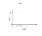
- FIG. 3A is a diagram showing a first example of the relationship between the temperature in the heating furnace and time.
- FIG. 3B is a diagram showing a second example of the relationship between the temperature in the heating furnace and time.
- FIG. 4 is a diagram showing an example of a DSC curve of an Fe-based nanocrystalline alloy ribbon.
- the present inventors have made intensive studies to shorten the production time of Fe-based amorphous alloy ribbons. As a result, the present inventors found that even if heat treatment is performed at a temperature equal to or higher than the crystallization temperature of bccFe crystals, if the heat treatment time is short, the crystallization of bccFe crystals can be suppressed and the Fe-based amorphous alloy thin film can be obtained. It was found that the internal stress (distortion) of the band can be suppressed.
- the intermetallic compound is an intermetallic compound that can be generated in the Fe-based amorphous alloy ribbon by heating the starting material of the Fe-based amorphous alloy ribbon.
- the intermetallic compound crystallizes at a temperature higher than the crystallization temperature of the intermetallic compound.
- the intermetallic compound is a factor that significantly deteriorates the magnetic properties of the Fe-based amorphous alloy ribbon.
- the present inventors have found that even if the heat treatment is performed at a temperature higher than the crystallization temperature of the intermetallic compound, if the heat treatment time is shorter, the crystallization of the bccFe crystal is suppressed, and the Fe-based amorphous It was found that the crystallization of the intermetallic compound can be suppressed in addition to suppressing the internal stress (strain) of the alloy ribbon.
- FIG. 1 is a flow chart illustrating an example of a method for producing an Fe-based amorphous alloy ribbon.
- the method for producing an Fe-based amorphous alloy ribbon includes a starting material production step (S101), an adjustment step (S102), and a heat treatment step (S103). As a process other than these, a known process for manufacturing an Fe-based amorphous alloy ribbon may be added.
- a starting material for the Fe-based amorphous alloy ribbon is manufactured.
- the starting material for the Fe-based amorphous alloy ribbon is an Fe-based amorphous alloy ribbon that has not undergone heat treatment in the heat treatment step (S103).
- a starting material for the Fe-based amorphous alloy ribbon is produced by a known method such as a single roll method or a twin roll method. Therefore, detailed description of the manufacturing method of the starting material for the Fe-based amorphous alloy ribbon is omitted here.
- the composition of the starting material for the Fe-based amorphous alloy ribbon may be determined according to the properties required for the Fe-based amorphous alloy ribbon. Any one of the following (a) to (l) is exemplified as a starting material for the Fe-based amorphous alloy ribbon.
- Fe—B—P amorphous alloy ribbon containing 70 atomic % or more of Fe, 2 atomic % or more and 25 atomic % or less of B, and 1 atomic % or more and 20 atomic % or less of P
- Fe—P amorphous alloy ribbon containing 80 atomic % or more of Fe and 8 atomic % or more and 20 atomic % or less of P
- 70 atomic % or more of Fe and 2 atomic % or more of 20 Fe—P—C amorphous alloy ribbon (k) containing 70 atomic % or more of P and 0.5 atomic % or more and 10 atomic % or less of C, and 2 atomic % or more of 20 Fe--Si--P amorphous alloy ribbon (l) containing 70 atomic % or more of Si and 4 atomic % or more and 20 atomic % or less of P, and 2 atomic % or more and 20 atomic % or less of Fe Fe—Si—P—C amorphous alloy ribbon containing the following Si, 4 atomic % or more and 20 atomic % or less of P, and 0.5 atomic % or more and 10 atomic % or less of C
- part of Fe may be replaced with 10 atomic % or less of Ni or 10 atomic % or less of Co.
- 2 atomic % or less of unavoidable impurities may be contained.
- the unavoidable impurities are S, N, O, Al and the like.
- the thickness of the starting material for the Fe-based amorphous alloy ribbon may be determined according to the properties required for the Fe-based amorphous alloy ribbon.
- the thickness of the starting material of the Fe-based amorphous alloy ribbon is, for example, within the range of 5 ⁇ m or more and 50 ⁇ m or less.
- an insulating film such as oxide or nitride may be formed on the surface of the Fe-based amorphous alloy ribbon.
- the size of the starting material of the Fe-based amorphous alloy ribbon is adjusted so that the starting material of the Fe-based amorphous alloy ribbon can be put into the heating furnace used in the heat treatment step (S103). and/or shape.
- the Fe-based amorphous alloy ribbon is adjusted so that the Fe-based amorphous alloy ribbon manufactured by heat treatment in the heat treatment step has a size and shape corresponding to the magnetic product to which it is applied. At least one of the size and shape of the starting material is adjusted.
- the magnetic product to which the Fe-based amorphous alloy ribbon manufactured by heat treatment in the heat treatment process is applied is not limited.
- Such magnetic products are, for example, electrical equipment (including electronic parts) having iron cores and magnetic (electromagnetic) shield plates.
- the electrical equipment may be any electrical equipment provided with an iron core.
- the electric device is, for example, an inductor such as a choke coil.
- the starting material of the Fe-based amorphous alloy ribbon cut to the same width as the wound core is cut so as to have the same inner diameter and outer diameter as the wound core. to wind.
- the magnetic shield plate is a single plate
- the Fe-based amorphous alloy is obtained by cutting the starting material of the Fe-based amorphous alloy ribbon into the same size and shape as the size and shape of the magnetic shield plate.
- the ribbon starting material is made into a single plate that constitutes the magnetic shield plate.
- the starting material of the Fe-based amorphous alloy ribbon is processed so as to form the curved portion.
- a magnetic product may be produced by combining a magnetic material whose magnetic properties are less deteriorated at the temperature of the heat treatment process and an Fe-based amorphous alloy ribbon.
- a magnetic material whose magnetic properties are less deteriorated at the temperature of the heat treatment process is, for example, at least one of a thin plate such as an electromagnetic steel sheet and permalloy, and a magnetic powder processed product such as ferrite and sendust.
- the starting material of the Fe-based amorphous alloy ribbon produced in the starting material production process may be heat treated in the heat treatment process without executing the adjustment process.
- FIG. 2 is a diagram showing an example of the DSC curve 201 of the Fe-based amorphous alloy ribbon.
- a DSC curve is measured with a differential scanning calorimeter (DSC).
- DSC differential scanning calorimeter
- An exothermic reaction occurs in the Fe-based amorphous alloy ribbon when the temperature rises.
- the DSC curve 201 of the Fe-based amorphous alloy ribbon is represented by temperature on the horizontal axis with the positive direction on the right side and heat flow (heat amount) on the vertical axis with the positive direction on the upper side.
- convex upward peaks are obtained as peaks 201a and 201b corresponding to the exothermic reaction.
- the peak appearing at the lowest temperature is the peak 201a indicating the exothermic reaction for crystallization of the bccFe crystal.
- the crystal of the bccFe crystal A mountain 201b that appears next to the mountain 201a indicating an exothermic reaction for crystallization is a mountain 201b that indicates an exothermic reaction for crystallization of the intermetallic compound.
- the intermetallic compound is determined according to the starting material of the Fe-based amorphous alloy ribbon. In the Fe—B amorphous alloy ribbon, the intermetallic compound is, for example, Fe 2 B, Fe 3 B, Fe 23 B 6 ).
- the starting material of the Fe-based amorphous alloy ribbon is heat-treated at a heat treatment temperature Tan equal to or higher than the crystallization temperature Tx1 of the bccFe crystal.
- the crystallization temperature Tx1 of the bccFe crystal is the temperature of the starting material for the Fe-based amorphous alloy ribbon at any timing between the start of crystallization of the bccFe crystal and the maximum production rate of the bccFe crystal. Respond to temperature.
- the crystallization temperature Tx1 of the bccFe crystal is determined from the peak 201a indicating the exothermic reaction for crystallization of the bccFe crystal.
- the crystallization temperature Tx1 of the bccFe crystal is, for example, the crystallization start temperature Tx1s of the bccFe crystal (the temperature at the rising point 211 of the peak 201a) shown in FIG. (the temperature at the position of the peak 212 of the mountain 201a).
- the crystallization start temperature Tx1s of the bccFe crystal corresponds to the temperature at which crystallization of Fe starts.
- the crystallization start temperature Tx1s of the bccFe crystal is the temperature on the DSC curve 201 of the Fe-based amorphous alloy ribbon, and is the rising point of the peak 201a indicating the exothermic reaction for crystallization of the bccFe crystal.
- 211 is the temperature.
- the temperature at the rising point 211 corresponds to the temperature obtained as follows.
- the crystallization peak temperature Tx1p of the bccFe crystal corresponds to the temperature at which the formation rate of the bccFe crystal is maximized.
- the crystallization peak temperature Tx1p of the bccFe crystal is the temperature on the DSC curve 201 of the Fe-based amorphous alloy ribbon, and is the peak 212 of the peak 201a indicating the exothermic reaction for crystallization of the bccFe crystal. is the temperature at the position of This position becomes 0 (zero) on the first order differential curve of the DSC curve 201 described above.
- the heating rate was 10° C./min, and the atmosphere was a nitrogen gas atmosphere. A differential scanning calorimeter measurement is performed.
- the crystallization temperature Tx1 of the bccFe crystal can be uniquely determined. From the viewpoint of suppressing the crystallization of the bccFe crystal more reliably, the starting material of the Fe-based amorphous alloy ribbon is heat-treated at a heat treatment temperature Tan equal to or higher than the crystallization start temperature Tx1s of the bccFe crystal (the heat treatment temperature is lowered). is preferred.
- the starting material of the Fe-based amorphous alloy ribbon is heat-treated at a heat treatment temperature Tan equal to or higher than the crystallization peak temperature Tx1p of the bccFe crystal. (increase the heat treatment temperature).
- the heat treatment time at the heat treatment temperature equal to or higher than the crystallization temperature Tx1 of the bccFe crystal is less than 10 seconds, the internal stress of the starting material of the Fe-based amorphous alloy ribbon cannot be sufficiently suppressed.
- the heat treatment time exceeds 1200 seconds at a temperature equal to or higher than the crystallization temperature Tx1 of the bccFe crystals, the content of the bccFe crystals in the Fe-based amorphous alloy ribbon increases.
- the heat treatment time ⁇ t an when the starting material of the Fe-based amorphous alloy ribbon is heat-treated at a temperature equal to or higher than the crystallization temperature Tx1 of the bccFe crystal is set to 10 seconds to 1200 seconds (20 minutes).
- the time shall be selected from the following range.
- the heat treatment temperature Tan is the crystallization temperature of the intermetallic compound.
- the temperature should be less than Tx2. In this way, inclusion of an intermetallic compound in the Fe-based amorphous alloy ribbon can be further suppressed.
- the crystallization temperature Tx2 of the intermetallic compound is the Fe-based amorphous alloy at any timing between the start of crystallization of the intermetallic compound and the maximum rate of crystal formation of the intermetallic compound. Corresponds to the temperature of the ribbon starting material. Also, the crystallization temperature Tx2 of the intermetallic compound is determined from the peak 201b indicating the exothermic reaction for crystallization of the intermetallic compound. Specifically, the crystallization temperature Tx2 of the intermetallic compound is, for example, the crystallization start temperature Tx2s of the intermetallic compound shown in FIG. 2 or the crystallization peak temperature Tx2p of the intermetallic compound shown in FIG.
- the crystallization start temperature Tx2s of the intermetallic compound corresponds to the temperature at which crystallization of the intermetallic compound starts.
- the crystallization start temperature Tx2s of the intermetallic compound is the temperature on the DSC curve 201 of the Fe-based amorphous alloy ribbon, and the rise of the peak 201b indicating the exothermic reaction for crystallization of the intermetallic compound. It is the temperature at the location of point 221 .
- the temperature at the position of the rising point 221 of the peak 201b shows an exothermic reaction for crystallization of the bccFe crystal, and the region on the higher temperature side than the position of the peak 212 of the peak 201a and the exothermic reaction for crystallization of the intermetallic compound.
- the differential value is 0 ( 0) or higher.
- a region on the higher temperature side than the position of the peak 212 of the peak 201a showing the exothermic reaction for the crystallization of the bccFe crystal and the crystallization of the intermetallic compound Depending on the composition of the starting material of the Fe-based amorphous alloy ribbon, a region on the higher temperature side than the position of the peak 212 of the peak 201a showing the exothermic reaction for the crystallization of the bccFe crystal and the crystallization of the intermetallic compound.
- the formation of both (bccFe crystals and intermetallic compound crystals) occurs continuously in the region between the position of the peak 222 of the mountain 201b indicating the exothermic reaction for the heat generation and the region on the lower temperature side.
- the peak 201b showing the exothermic reaction for crystallization of the intermetallic compound may not be clearly defined.
- the DSC curve 201 in the region between the peaks 201a and 201b can be obtained by using a predetermined function in which the number of local maximum values is 0 (zero) and the number of local minimum values is 1. After approximation, the first derivative curve of the DSC curve 201 may be created.
- the crystallization peak temperature Tx2p of the intermetallic compound corresponds to the temperature at which the rate of crystal formation of the intermetallic compound is maximized.
- the crystallization peak temperature Tx2p of the intermetallic compound is the temperature on the DSC curve 201 of the Fe-based amorphous alloy ribbon, and is the temperature of the peak 201b indicating the exothermic reaction for crystallization of the intermetallic compound. is the temperature at the location of peak 222; This position becomes 0 (zero) on the first order differential curve of the DSC curve 201 described above.
- the heating rate was 10° C./min, and the atmosphere was nitrogen gas. Differential scanning calorimeter measurements are carried out as atmosphere.
- the crystallization temperature Tx2 of the intermetallic compound can be uniquely determined. From the viewpoint of more reliably suppressing the crystallization of the intermetallic compound, the starting material of the Fe-based amorphous alloy ribbon is heat treated at a heat treatment temperature Tan lower than the crystallization start temperature Tx2s of the intermetallic compound (the heat treatment temperature is lower) is preferable.
- the starting material of the Fe-based amorphous alloy ribbon is heated at a heat treatment temperature Tan lower than the crystallization peak temperature Tx2p of the intermetallic compound. It is preferable to heat-treat (increase the heat-treating temperature).
- the starting material of the Fe-based amorphous alloy ribbon can be heat treated at a heat treatment temperature Tan equal to or higher than the crystallization temperature Tx2 of the intermetallic compound.
- the heat treatment time ⁇ tan when the starting material of the Fe-based amorphous alloy ribbon is heat-treated at the heat treatment temperature Tan equal to or higher than the crystallization temperature Tx2 of the intermetallic compound is 3 seconds to 240 seconds (4 minutes).
- the time shall be selected from the following range.
- the heat treatment time is less than 3 seconds at a temperature equal to or higher than the crystallization temperature Tx2 of the intermetallic compound, the internal stress of the starting material of the Fe-based amorphous alloy ribbon cannot be sufficiently suppressed.
- the heat treatment time exceeds 4 minutes at a temperature equal to or higher than the crystallization temperature Tx2 of the intermetallic compound, the content of the intermetallic compound in addition to the bccFe crystal in the Fe-based amorphous alloy ribbon become more.
- the crystallization temperature Tx2 of the intermetallic compound is, for example, the crystallization start temperature Tx2s of the intermetallic compound shown in FIG. 2 or the crystallization peak temperature Tx2p of the intermetallic compound shown in FIG.
- the starting material of the Fe-based amorphous alloy ribbon is heat-treated at a heat treatment temperature Tan equal to or higher than the crystallization start temperature Tx2s of the intermetallic compound (the heat treatment temperature is lower) is preferred.
- the starting material of the Fe-based amorphous alloy ribbon is heated at a heat treatment temperature Tan equal to or higher than the crystallization peak temperature Tx2p of the intermetallic compound. It is preferable to heat-treat (increase the heat-treating temperature).
- the heat treatment temperature Tan is the Fe-based amorphous alloy A temperature below the melting point of the ribbon starting material.
- the heating furnace used for heat-treating the starting material of the Fe-based amorphous alloy ribbon is not limited.
- the heating furnace used for heat-treating the starting material of the Fe-based amorphous alloy ribbon may be an electric furnace, a combustion furnace, an induction heating furnace, or an infrared concentrating heating furnace. Also good.
- the heating furnace used for heat-treating the starting material of the Fe-based amorphous alloy ribbon may be a continuous heating furnace or a batch heating furnace.
- a continuous heating furnace transportation of the object to be heated into the heating furnace, heating (heat treatment) of the object to be heated in the heating furnace, and transportation of the object to be heated from the inside of the heating furnace to the outside are sequentially performed. (continuously) to heat (heat-treat) the object to be heated while being conveyed in the heating furnace.
- a batch-type heating furnace inserting the objects to be heated into the heating furnace, heating the objects to be heated in the heating furnace (heat treatment), and and taking out the object to be heated from the inside of the heating furnace to the outside.
- the position of the object to be heated does not change during heating (heat treatment) in the heating furnace.
- the atmosphere of the heating furnace is not limited.
- the atmosphere of the heating furnace may be, for example, air, steam atmosphere, dry air atmosphere, inert atmosphere, or vacuum atmosphere.
- the atmosphere of the heating furnace may be an atmosphere combining at least two of these atmospheres.
- heat treatment is performed at a heat treatment temperature Tan equal to or higher than the crystallization temperature Tx1 of the bccFe crystal, and for a heat treatment time ⁇ t an in the range of 10 seconds to 1200 seconds.
- the total heating time ⁇ t all is preferably, for example, 28800 seconds (480 minutes) or less.
- the total heating time ⁇ t all is preferably, for example, 12000 seconds (200 minutes) or less.
- the total heating time ⁇ t all is the time during which the starting material of the Fe-based amorphous alloy ribbon is heated in the heat treatment step, and the time during which the Fe-based amorphous alloy ribbon is heated in the heating furnace. be.
- the total heating time ⁇ t all is determined, for example, according to the temperature control method and performance within the heating furnace. From the viewpoint of shortening the production time of the Fe-based amorphous alloy ribbon, it is preferable to select the temperature control method and performance of the heating furnace so that the total heating time ⁇ t all is shortened.
- 3A and 3B are diagrams showing an example of the relationship between the temperature in the heating furnace and time. As shown in FIG. 3A, when the starting material of the Fe-based amorphous alloy ribbon is placed in a heating furnace in which the temperature in the heating furnace is kept at the heat treatment temperature Tan , the total heating time ⁇ t all is the heat treatment temperature. It is equal to the heat treatment time ⁇ tan for heat treatment at Tan .
- the temperature in the heating furnace is maintained at the heat treatment temperature Tan for the heat treatment time ⁇ tan , and then heated.
- the total heating time ⁇ t all is the heat treatment time ⁇ t an plus the heating time ⁇ t u and the cooling time ⁇ t d .
- FIG. 3B illustrates the case where the temperature in the heating furnace is raised from the room temperature Tr to the heat treatment temperature Tan at a constant temperature elevation rate.
- the case where the temperature in the heating furnace is lowered from the heat treatment temperature Tan to the normal temperature Tr at a temperature lowering rate is exemplified.
- the temperature increase rate and temperature decrease rate may not be constant.
- the temperature increase rate and temperature decrease rate may be temporarily set to 0 (ie, the temperature may be increased and decreased stepwise).
- the temperature change in the heating furnace when the temperature is raised or lowered may be determined, for example, according to the temperature control capability of the heating furnace.
- FIGS. 3A and 3B illustrate the case where the starting material of the Fe-based amorphous alloy band is subjected to heat treatment once at heat treatment temperature Tan for heat treatment time ⁇ tan .
- the total value of the heat treatment time at the heat treatment temperature Tan is the heat treatment time ⁇ t described in [First example of heat treatment temperature and heat treatment time] and [Second example of heat treatment temperature and heat treatment time]. If it is within the range of an , the heat treatment for the starting material of the Fe-based amorphous alloy strip may be performed in two or more steps.
- the total heating time ⁇ t all is not the heating time of each time but the total value of the heating times of each time.
- the heat treatment may be performed in two or more heating furnaces. Further, in the same heating furnace, the temperature is raised to the heat treatment temperature Tan described in [First example of heat treatment temperature and heat treatment time] and [Second example of heat treatment temperature and heat treatment time], and the heat treatment temperature T The maintenance of an and the temperature drop from the heat treatment temperature Tan may be repeated two or more times.
- the DC magnetic field may or may not be applied to the starting material of the Fe-based amorphous alloy belt.
- a DC magnetic field is applied to the starting material of the Fe-based amorphous alloy band, even if the time during which the DC magnetic field is applied includes the time during which the heat treatment is performed at the heat treatment temperature Tan . It doesn't have to be.
- the starting material for the Fe-based amorphous alloy ribbon is heat-treated by the heat treatment process described above, and the Fe-based amorphous alloy ribbon with reduced internal stress is produced.
- the crystal size of the bccFe crystals is preferably 0.1 ⁇ m or more and 5000 ⁇ m or less.
- the crystal size of bccFe crystals in the Fe-based amorphous alloy ribbon after the heat treatment step is, for example, preferably less than 100 ⁇ m, more preferably less than 50 ⁇ m, and even more preferably less than 10 ⁇ m.
- the crystal size is, for example, a value calculated from the half width of the peak of diffraction lines obtained by X-ray diffraction.
- the heat treatment temperature Tan is equal to or higher than the crystallization start temperature Tx1s of the bccFe crystal and lower than the melting point of the Fe-based amorphous alloy ribbon, and the heat treatment time ⁇ t an is in the range of 3 seconds to 1200 seconds. , heat-treating the starting material of the Fe-based amorphous alloy ribbon. Therefore, even if the heat treatment time for relaxing the internal stress of the Fe-based amorphous alloy ribbon is shortened, crystallization of bccFe crystals and intermetallic compounds can be suppressed. Therefore, the production time of the Fe-based amorphous alloy ribbon can be shortened.
- the heat treatment temperature T an is equal to or higher than the crystallization start temperature Tx1s of the bccFe crystal and lower than the crystallization start temperature Tx2s of the intermetallic compound, and the heat treatment time ⁇ t an is in the range of 10 seconds to 1200 seconds.
- a starting material for the amorphous alloy ribbon is heat treated. Therefore, crystallization of the intermetallic compound can be further suppressed.
- the heat treatment temperature T an is equal to or higher than the crystallization start temperature Tx2s of the intermetallic compound and lower than the melting point of the Fe-based amorphous alloy ribbon, and the heat treatment time ⁇ t an is in the range of 3 seconds to 240 seconds, A starting material for the Fe-based amorphous alloy ribbon is heat-treated. Therefore, the heat treatment time for relaxing the internal stress of the Fe-based amorphous alloy ribbon can be shortened.
- the starting material of the Fe-based amorphous alloy ribbon is heat-treated at a heat treatment temperature T an equal to or higher than the crystallization start temperature Tx1s of the bccFe crystal, and for a heat treatment time ⁇ t an in the range of 10 seconds to 1200 seconds.
- the total heating time ⁇ t all is set to 28800 seconds or less.
- the heat treatment temperature T an equal to or higher than the crystallization start temperature Tx2s of the intermetallic compound, the heat treatment time ⁇ t an in the range of 3 seconds or more and 240 seconds or less, and the total amount of heat treatment of the Fe-based amorphous alloy ribbon starting material
- the heating time ⁇ t all is set to 12000 seconds or less. Therefore, the time during which the Fe-based amorphous alloy ribbon is in the heating furnace can be shortened, thereby shortening the production time of the Fe-based amorphous alloy ribbon.
- the present inventors have made extensive studies to shorten the production time of Fe-based nanoalloy ribbons. As a result, the present inventors found that even if heat treatment is performed at a temperature higher than the crystallization peak temperature Tx1p, which is the maximum crystallization temperature Tx1 of bccFe crystals, if the heat treatment time is short, good bccFe crystals can be obtained. It has been found that the internal stress (strain) of the Fe-based nanocrystalline alloy ribbon can be suppressed while promoting the transformation.
- the intermetallic compound is an intermetallic compound that can be produced by heating the starting material of the Fe-based nanocrystalline alloy ribbon.
- the intermetallic compounds that can be produced in the Fe—B nanocrystalline alloy ribbon by heating the starting material of the Fe nanocrystalline alloy ribbon are, for example, Fe 2 B, Fe 3 B, and Fe 23 B 6 .
- the present inventors found that the crystallization end temperature Tx1f of the bccFe crystal is higher than the heat treatment at a temperature above the crystallization peak temperature Tx1p of the bccFe crystal and below the crystallization end temperature Tx1f of the bccFe crystal. It was found that the heat treatment at high temperature can suppress the internal stress (strain) of the Fe-based nanocrystalline alloy ribbon while promoting good crystallization of the bccFe crystal in a shorter heat treatment time.
- the intermetallic compound crystallizes at a temperature higher than the crystallization temperature of the intermetallic compound.
- the intermetallic compound is a factor that significantly deteriorates the magnetic properties of the Fe-based nanocrystalline alloy ribbon.
- the present inventors have found that even if the heat treatment is performed at a temperature higher than the crystallization temperature of the intermetallic compound, if the heat treatment time is shortened further, good crystallization of the bccFe crystal is promoted while Fe In addition to suppressing the internal stress (strain) of the nanocrystalline alloy ribbon, it was found that the crystallization of the intermetallic compound can be suppressed.
- Method for producing Fe-based nanocrystalline alloy ribbon An example of a method for producing an Fe-based nanocrystalline alloy ribbon will be described. An example of the method for producing the Fe-based nanocrystalline alloy ribbon can be realized by the same flow chart as the flow chart shown in FIG.
- the method for producing an Fe-based nanocrystalline alloy ribbon also includes a starting material production step (S101), an adjustment step (S102), and a heat treatment step (S103). In addition, as a process other than these, a known process for manufacturing the Fe-based nanocrystalline alloy ribbon may be added.
- a starting material for the Fe-based nanocrystalline alloy ribbon is manufactured.
- the starting material for the Fe-based nanocrystalline alloy ribbon is an Fe-based amorphous alloy ribbon that has not undergone heat treatment in the heat treatment step.
- the starting material for the Fe-based nanocrystalline alloy ribbon is manufactured using a known method such as a single roll method or a twin roll method. Therefore, detailed description of the manufacturing method of the starting material for the Fe-based nanocrystalline alloy ribbon is omitted here.
- composition of the starting material for the Fe-based nanocrystalline alloy ribbon may be determined according to the properties required for the Fe-based nanocrystalline alloy ribbon. Any one of a) to (f) is exemplified.
- Fe—B amorphous alloy ribbon containing 75 atomic % or more of Fe and 8 atomic % or more and 25 atomic % or less of B
- M 60 atomic % or more of Fe and 2 atomic % or more of 25 Si at atomic % or less, B at 2 atomic % or more and 25 atomic % or less, and M at 1 atomic % or more and 10 atomic % or less
- M is Nb, Mo, Ta, W, Ti, V, Cr, Mn, Zr , Hf, Y, P, and C, which is an element group containing at least one selected from the group consisting of Fe—Si—BM amorphous alloy ribbon
- c containing 70 atomic % or more of Fe; , 1 atomic % or more and 12 atomic % or less of B and 6 atomic % or more and 20 atomic % or less of M
- M is Nb, Mo, Ta, W, Ti, V, Cr, Mn, Zr, Hf, Y
- M is an element group containing at least one selected from Nb, Mo, Ta, W, Ti, V, Cr, Mn, Zr, Hf, Y, P, and C Fe—Al—BM amorphous alloy ribbon containing
- Cu may be contained in an amount of 2 atomic % or less. Further, in (a) to (f), part of Fe may be replaced with 10 atomic % or less of Ni or 10 atomic % or less of Co. In (a) to (f), 2 atomic % or less of unavoidable impurities may be contained. The unavoidable impurities are S, N, O and the like.
- the thickness of the starting material for the Fe-based nanocrystalline alloy ribbon may be determined according to the properties required for the Fe-based nanocrystalline alloy ribbon. The thickness of the starting material of the Fe-based nanocrystalline alloy ribbon is, for example, within the range of 5 ⁇ m or more and 50 ⁇ m or less. Further, an insulating film such as oxide or nitride may be formed on the surface of the Fe-based nanocrystalline alloy ribbon.
- the adjustment step is, for example, a step in which the starting material for the Fe-based amorphous alloy ribbon is replaced with the starting material for the Fe-based nanocrystalline alloy ribbon in the description of the adjustment step in the first embodiment. Therefore, detailed description of the adjustment process is omitted here.
- the magnetic product to which the Fe-based nanocrystalline alloy ribbon is applied is described in the description of the magnetic product to which the Fe-based amorphous alloy ribbon is applied in the description of the preparation process of the first embodiment. It is a magnetic product in which the crystalline alloy ribbon is read as the Fe-based nanocrystalline alloy ribbon.
- FIG. 4 is a diagram showing an example of a DSC curve 401 of an Fe-based nanocrystalline alloy ribbon.
- an exothermic reaction occurs when the temperature rises in the Fe-based nanocrystalline alloy ribbon.
- the DSC curve 401 of the Fe-based nanocrystalline alloy ribbon is obtained by setting the temperature on the horizontal axis with the positive direction on the right side and the heat flow (heat amount) on the vertical axis with the positive direction on the upper side.
- upward convex peaks are obtained as peaks 401a, 401b corresponding to the exothermic reaction.
- the peak appearing at the lowest temperature is the peak 401a indicating the exothermic reaction for crystallization of the bccFe crystal.
- the bccFe crystal is crystallized.
- a mountain 401b appearing next to the mountain 401a indicating an exothermic reaction for crystallization is a mountain 401b indicating an exothermic reaction for crystallization of the intermetallic compound.
- the intermetallic compound is determined according to the starting material of the Fe-based nanocrystalline alloy ribbon.
- the intermetallic compounds are Fe 2 B, Fe 3 B, Fe 23 B 6 , for example.
- the starting material of the Fe-based nanocrystalline alloy ribbon is heat-treated at a heat treatment temperature Tan higher than the crystallization peak temperature Tx1p of the bccFe crystal.
- the crystallization peak temperature Tx1p of the bccFe crystals corresponds to the temperature of the starting material of the Fe nanocrystalline alloy ribbon when the formation rate of the bccFe crystals is maximized.
- the crystallization peak temperature Tx1p of the bccFe crystal is the temperature at the peak 412 of the mountain 401a.
- the heat treatment temperature Tan above the crystallization peak temperature Tx1p of the bccFe crystal for example, a heat treatment temperature above the crystallization end temperature Tx1f of the bccFe crystal and below the melting point of the starting material of the Fe-based nanocrystalline alloy ribbon is employed.
- the crystallization peak temperature Tx1p of the bccFe crystal and the crystallization end temperature Tx1f of the bccFe crystal are not included in the crystallization temperature Tx1 of the bccFe crystal. .
- the crystallization end temperature Tx1f of the bccFe crystal corresponds to the temperature at which the crystallization of Fe ends.
- the crystallization finish temperature Tx1f of the bccFe crystal is the temperature on the DSC curve 401 of the Fe-based nanocrystalline alloy ribbon, and is the falling point of the peak 401a indicating the exothermic reaction for crystallization of the bccFe crystal. 413 is the temperature at the position.
- the DSC curve 401 of the Fe-based non-nanocrystalline alloy ribbon shows peaks 201a, 401a showing an exothermic reaction for crystallization of bccFe crystals than the DSC curve 201 of the Fe-based amorphous alloy ribbon.
- the peaks 201b, 401b indicating the exothermic reaction for crystallization of the intermetallic compound are long. Therefore, it is assumed that the falling point 413 of the mountain 401a and the rising point 421 of the mountain 201b do not match (that is, the area between the mountains 401a and 401b where the slope of the tangent line changes from negative to 0 (zero) and 0 ( zero) to positive).
- the temperature at the position of the falling point 413 indicates the exothermic reaction for crystallization of the intermetallic compound and the region on the higher temperature side than the position of the peak 412 of the mountain 401a, which indicates the exothermic reaction for crystallization of the bccFe crystal.
- the differential value of 0 (zero) or more for the first time when tracing the first-order differential curve of the DSC curve 401 from the lower temperature side to the higher temperature side Corresponds to the temperature at which the value is reached.
- the shape of the area between the side area and the area between is complicated. In such a case, for example, there is one region where the slope of the tangent line changes from negative to 0 (zero) and another region where the slope of the tangent line changes from 0 (zero) to positive, and the region sandwiched between these regions is a straight line.
- the first embodiment As described above, the falling point 413 of the mountain 401a (rising point 421 of the mountain 401b) may be specified.
- the crystallization end temperature Tx1f of the bccFe crystal coincides with the crystallization start temperature Tx2s of the intermetallic compound.
- the heat treatment time is less than 2 seconds at a heat treatment temperature higher than the crystallization peak temperature Tx1p of the bccFe crystal, the crystallization of the bccFe crystal cannot be sufficiently promoted and the Fe-based nanocrystalline alloy ribbon cannot be produced. The internal stress of the material cannot be sufficiently suppressed.
- the heat treatment time exceeds 2700 seconds at a heat treatment temperature exceeding the crystallization peak temperature Tx1p of the bccFe crystal, there is a possibility that the crystallized bccFe crystal will not exist stably, and the Fe-based nanocrystalline alloy The content of intermetallic compound crystals contained in the ribbon increases.
- the heat treatment time ⁇ t an when the heat treatment is performed at a temperature higher than the crystallization peak temperature Tx1p of the bccFe crystal is selected from the range of 2 seconds or more and 2700 seconds (45 minutes) or less. .
- the heat treatment time ⁇ tan is set to 2 seconds or more and 1800 seconds (30 minutes) or less. Let the time be selected from the range.
- the crystallization temperature Tx2 of the intermetallic compound is, for example, the crystallization start temperature Tx2s of the intermetallic compound shown in FIG. crystallization peak temperature Tx2p (temperature at the position of peak 422) of the intercompound;
- the temperature at the rising point 421 of the peak 401b indicates an exothermic reaction for crystallization of the bccFe crystal
- the region on the higher temperature side than the position of the peak 412 of the peak 401a indicates an exothermic reaction for crystallization of the intermetallic compound.
- the second time when the first derivative curve of the DSC curve 401 is traced from the low temperature side to the high temperature side It corresponds to the temperature at which the value is equal to or above.
- the heat treatment time ⁇ t an when the starting material of the Fe-based nanocrystalline alloy ribbon is heat treated at the heat treatment temperature T an equal to or higher than the crystallization temperature Tx2 of the intermetallic compound is in the range of 2 seconds or more and 30 seconds or less. Let the time be selected from
- the heat treatment time ⁇ t an when the heat treatment is performed at a temperature equal to or higher than the crystallization temperature Tx2 of the intermetallic compound is selected from the range of 2 seconds or more and 30 seconds or less.
- Fe it is preferable to heat-treat the starting material of the nanocrystalline alloy ribbon (increase the heat treatment temperature).
- the starting material of the Fe-based nanocrystalline alloy ribbon is heat treated at a heat treatment temperature Tan equal to or higher than the crystallization peak temperature Tx2p of the intermetallic compound (heat treatment increasing the temperature).
- the heating furnace used for heat-treating the starting material for the Fe-based nanocrystalline alloy ribbon is not limited, similarly to the heating furnace used for heat-treating the starting material for the Fe-based amorphous alloy ribbon.
- the atmosphere of the heating furnace is also not limited.
- heat treatment is performed at a heat treatment temperature Tan higher than the crystallization peak temperature Tx1p of the bccFe crystal for a heat treatment time ⁇ t an in the range of 2 seconds or more and 2700 seconds or less.
- the total heating time ⁇ t all is preferably, for example, 18000 seconds (300 minutes) or less from the viewpoint of shortening the production time of the Fe-based nanocrystalline alloy ribbon.
- the production time of the Fe-based nanocrystalline alloy ribbon is shortened.
- the total heating time ⁇ t all is preferably, for example, 15000 seconds (250 minutes) or less.
- heat treatment is performed at a heat treatment temperature Tan equal to or higher than the crystallization start temperature Tx2s of the intermetallic compound and for a heat treatment time ⁇ t an in the range of 2 seconds to 30 seconds.
- the total heating time ⁇ t all is preferably, for example, 12000 seconds (200 minutes) or less.
- the total heating time ⁇ t all is the time during which the starting material of the Fe-based nanocrystalline alloy ribbon is heated in the heat treatment step, and the time during which the starting material of the Fe-based nanocrystalline alloy ribbon is heated in the heating furnace. is.
- the total heating time ⁇ t all is determined, for example, according to the temperature control method and performance in the heating furnace, as in the first embodiment.
- the relationship between the temperature in the heating furnace and the time is, for example, the relationship shown in FIGS. 3A and 3B.
- the relationship between temperature and time in the heating furnace is not limited to the relationship shown in FIGS. 3A and 3B.
- the temperature increase rate and temperature decrease rate may not be constant.
- the temperature increase rate and temperature decrease rate may be temporarily set to 0 (ie, the temperature may be increased and decreased stepwise).
- 3A and 3B illustrate the case where the starting material of the Fe-based nanocrystalline alloy band is subjected to heat treatment once at heat treatment temperature Tan for heat treatment time ⁇ tan .
- the total value of the heat treatment time at the heat treatment temperature Tan is the heat treatment time ⁇ t described in [First example of heat treatment temperature and heat treatment time] and [Second example of heat treatment temperature and heat treatment time]. If it is within the range of an , the heat treatment for the starting material of the Fe-based nanocrystalline alloy strip may be performed in two or more steps. Further, when the starting material of the Fe-based nanocrystalline alloy band is heat-treated in two or more steps, the total heating time ⁇ t all is not the heating time of each time but the total value of the heating time of each time.
- the heat treatment may be performed in two or more heating furnaces. Further, in the same heating furnace, the temperature is raised to the heat treatment temperature Tan described in [First example of heat treatment temperature and heat treatment time] and [Second example of heat treatment temperature and heat treatment time], and the heat treatment temperature T The maintenance of an and the temperature drop from the heat treatment temperature Tan may be repeated two or more times.
- the DC magnetic field may or may not be applied to the starting material of the Fe-based nanocrystalline alloy belt.
- the time during which the DC magnetic field is applied does not include the time during which the heat treatment is performed at the heat treatment temperature Tan .
- the starting material for the Fe-based nanocrystalline alloy ribbon is heat-treated by the heat treatment process described above, and an Fe-based nanocrystalline alloy ribbon with reduced internal stress is produced.
- the crystal size of ⁇ Fe is preferably 1 nm or more and 1000 nm or less.
- the crystal size of ⁇ Fe is, for example, preferably less than 1000 nm, more preferably less than 500 nm, even more preferably less than 100 nm.
- the crystal size is, for example, a value calculated from the half width of the peak of diffraction lines obtained by X-ray diffraction.
- the heat treatment temperature T an is higher than the crystallization peak temperature Tx1p of the bccFe crystal and lower than the melting point of the Fe-based nanocrystalline alloy ribbon, and the heat treatment time ⁇ t an is in the range of 2 seconds or more and 2700 seconds or less.
- a starting material for the Fe-based nanocrystalline alloy ribbon is heat-treated. Therefore, even if the heat treatment time for relaxing the internal stress of the Fe-based nanocrystalline alloy ribbon and crystallization of the bccFe crystal is shortened, the stable presence of the bccFe crystal and the crystallization of the intermetallic compound can be achieved. can be suppressed. Therefore, the manufacturing time of the Fe-based nanocrystalline alloy ribbon can be shortened.
- the heat treatment temperature T an is equal to or higher than the crystallization end temperature Tx1f of the bccFe crystal and lower than the melting point of the Fe-based nanocrystalline alloy ribbon, and the heat treatment time ⁇ t an is in the range of 2 seconds to 1800 seconds.
- the starting material for the nanocrystalline alloy ribbon is heat treated. Therefore, the bccFe crystal can exist more stably.
- the heat treatment temperature T an is equal to or higher than the crystallization start temperature Tx2s of the intermetallic compound and lower than the melting point of the Fe-based nanocrystalline alloy ribbon, and the heat treatment time ⁇ t an in the range of 2 seconds to 30 seconds, Fe A starting material for the nanocrystalline alloy ribbon is heat-treated. Therefore, the heat treatment time for relaxing the internal stress of the Fe-based nanocrystalline alloy ribbon and crystallization of the bccFe crystal can be shortened.
- the starting material of the Fe-based nanocrystalline alloy ribbon is heat-treated at a heat treatment temperature T an higher than the crystallization peak temperature Tx1p of the bccFe crystal, and for a heat treatment time ⁇ t an in the range of 2 seconds or more and 2700 seconds or less.
- the total heating time ⁇ t all is set to 18000 seconds or less.
- the heat treatment temperature T an equal to or higher than the crystallization end temperature Tx1f of the bccFe crystal
- the heat treatment time ⁇ t an in the range of 2 seconds or more and 1800 seconds or less
- the total heating time when the starting material of the Fe-based nanocrystalline alloy ribbon is heat treated ⁇ t all is set to 15000 seconds or less.
- the heat treatment temperature T an is equal to or higher than the crystallization start temperature Tx2s of the intermetallic compound, the heat treatment time T an is in the range of 2 seconds or more and 30 seconds or less, and the heat treatment time ⁇ t an is in the range of 2 seconds or more and 30 seconds or less.
- the total heating time ⁇ t all when heat-treating the starting material of the nanocrystalline alloy ribbon is set to 12000 seconds or less. Therefore, the time that the Fe-based nanocrystalline alloy ribbon is in the heating furnace can be shortened, thereby shortening the production time of the Fe-based nanocrystalline alloy ribbon.
- Example 1 In this example, an example relating to a method for producing an Fe-based amorphous alloy ribbon will be described.
- an Fe—Si—B amorphous alloy ribbon containing Febal., 9 atomic % Si, and 11 atomic % B was used as a starting material.
- a starting Fe—Si—B amorphous alloy ribbon was cut to a width of 10.00 mm.
- the starting material of the Fe—Si—B amorphous alloy ribbon having a width of 10.00 mm thus obtained was wound to have an outer diameter of 17.8 mm, an inner diameter of 11.0 mm, and a height of 10 mm.
- the shape was the same as that of the amorphous core of 0.0 mm.
- the starting material of the Fe—Si—B amorphous alloy ribbon was measured by a differential scanning calorimeter to create a DSC curve, and from the DSC curve, as described above, the crystallization of the bccFe crystal was performed.
- the heating furnace As the heating furnace, a batch-type electric furnace having an air atmosphere was used. In the heat treatment step, the conditions other than the heat treatment time were the same, and the starting material of each Fe—Si—B amorphous alloy ribbon was heat treated to produce the Fe—Si—B amorphous alloy ribbon. . At this time, no DC magnetic field was applied to the starting material of the Fe--Si--B amorphous alloy ribbon in the heating furnace. The properties of the Fe -- Si--B amorphous alloy ribbon thus produced were evaluated.
- the starting material for the Fe—Si—B amorphous alloy ribbon is the amorphous core-shaped starting material described above, and in the present example, the Fe—Si—B amorphous
- the starting material for the quality alloy ribbon is the aforementioned amorphous core.
- the value of the iron loss P cv is 1250 kW / m 3 or less, Fe-Si-B amorphous alloy Reduction of the internal stress (strain) of the ribbon, suppression of the formation of bccFe crystals, and suppression of the formation of intermetallic compounds were assumed to be realized within a satisfactory range as a product.
- the iron loss Pcv is small and the relative magnetic permeability ⁇ r is large, the internal stress (strain) of the Fe-based amorphous alloy ribbon can be reduced, and the bccFe crystal and intermetallic compound can be reduced. It can be evaluated that the suppression of the generation is more reliably realized.
- the value of the relative permeability ⁇ r is 100 or more.
- the value of the relative magnetic permeability ⁇ r is the value when the frequency is 100 kHz and the magnetic field strength Hm is 0.4 A/m.
- the value of iron loss P cv is the value when the frequency is 100 kHz and the magnetic flux density B m is 100 mT.
- Fe—Si—B amorphous alloy ribbons were produced by changing the heat treatment temperature and heat treatment time, and relative magnetic permeability ⁇ r and core loss P cv were measured for each Fe—Si—B amorphous alloy ribbon. It was measured. Table 1 shows the results.
- “O (white circle)” shown in the remarks column of Table 1 indicates that the value of relative magnetic permeability ⁇ r is 100 or more and the value of iron loss P cv is 1250 kW / m 3 or less (i.e. , “ ⁇ (white circle)” indicates an invention example).
- “x (cross mark)” shown in the remarks column of Table 1 indicates that the value of relative magnetic permeability ⁇ r did not exceed 100 and the value of iron loss P cv did not reach 1250 kW/m 3 or less. (that is, "x (cross mark)” indicates that it is a comparative example).
- the starting material of the Fe—Si—B amorphous alloy ribbon was heat treated for less than 10 seconds, the value of iron loss P cv did not become 1250 kW/ m3 or less, and the value of relative magnetic permeability ⁇ r did not become 100 or more. (See numbers 7-8).
- the starting material of the Fe—Si—B amorphous alloy ribbon When the heat treatment time exceeds 1200 seconds, the value of iron loss P cv did not become 1250 kW/ m3 or less, and the value of relative magnetic permeability ⁇ r did not become 100 or more ( see number 12)
- the heat treatment temperature is less than 3 seconds.
- the value of iron loss P cv did not go below 1250 kW/m 3 and the value of relative permeability ⁇ r did not go above 100 (see numbers 20 and 23).
- Example 2 In this example, an example relating to a method for producing an Fe-based nanocrystalline alloy ribbon will be described.
- Fe—Si—BM amorphous alloy ribbon containing Febal., 15 atomic percent Si, 7 atomic percent B, 3 atomic percent Nb, and 1 atomic percent Cu was used as the starting material.
- the starting material of the Fe--Si--BM nanocrystalline alloy ribbon was cut to have a width of 5.0 mm.
- the thus obtained starting material of the Fe—Si—BM nanocrystalline alloy ribbon with a width of 5.0 mm was wound to have an outer diameter of 8.9 mm, an inner diameter of 6.5 mm, and a height of It had the same shape as the 5.0 mm nanocrystal core.
- the heating furnace a batch-type electric furnace having an air atmosphere was used.
- the conditions other than the heat treatment time are the same, and the starting material of each Fe—Si—BM nanocrystalline alloy ribbon is heat treated to obtain the Fe—Si—BM nanocrystalline alloy ribbon. manufactured.
- no DC magnetic field was applied to the starting material of the Fe--Si--BM nanocrystalline alloy ribbon in the heating furnace.
- the properties of the Fe--Si--BM nanocrystalline alloy ribbon thus produced were evaluated.
- relative magnetic permeability ⁇ r and core loss P cv were used as evaluation indexes.
- the starting material of the Fe--Si--BM nanocrystalline alloy ribbon is the starting material shaped into the nanocrystalline core described above.
- the Fe--Si--BM nanocrystalline alloy ribbon to be produced is the aforementioned nanocrystalline core.
- the value of the relative magnetic permeability ⁇ r is 12500 or more, and the iron loss P cv is If the value is 100 kW/m 3 or less, the internal stress (strain) of the Fe—Si—BM nanocrystalline gold ribbon is reduced, the crystallization of the bccFe crystal is promoted, and the formation of intermetallic compounds is suppressed. It was assumed that the product was realized within a satisfactory range.
- the value of the relative magnetic permeability ⁇ r is the value when the frequency is 100 kHz and the magnetic field strength Hm is 0.4 A/m.
- the value of iron loss P cv is the value when the frequency is 100 kHz and the magnetic flux density B m is 100 mT.
- Fe—Si—BM nanocrystalline alloy ribbons were produced by changing the heat treatment temperature and heat treatment time, and relative magnetic permeability ⁇ r and iron loss P were measured for each Fe—Si—BM nanocrystalline alloy ribbon. cv was measured. Table 2 shows the results.
- ⁇ (white circle) and “ ⁇ (triangle)” shown in the remarks column of Table 2 indicate that the value of relative magnetic permeability ⁇ r is 12500 or more and the value of iron loss P cv is 1250 kW / m 3 or less. (That is, “ ⁇ (white circle)” and “ ⁇ (triangle)” indicate invention examples).
- “O (white circle)” shown in the remarks column of Table 2 indicates that the value of the relative magnetic permeability ⁇ r is larger and is more preferable.
- x (cross mark)” shown in the remarks column of Table 1 indicates that the value of relative magnetic permeability ⁇ r was not 12500 or more and the value of iron loss P cv was not 100 kW/m 3 or less. (that is, “x (cross mark)” indicates that it is a comparative example).
- the heat treatment time is 2 seconds to 1800 seconds.
- Tx1f the crystallization end temperature
- the present invention can be used, for example, to produce Fe-based alloy ribbons.
Landscapes
- Chemical & Material Sciences (AREA)
- Engineering & Computer Science (AREA)
- Physics & Mathematics (AREA)
- Thermal Sciences (AREA)
- Dispersion Chemistry (AREA)
- Power Engineering (AREA)
- Electromagnetism (AREA)
- Crystallography & Structural Chemistry (AREA)
- Mechanical Engineering (AREA)
- Materials Engineering (AREA)
- Metallurgy (AREA)
- Organic Chemistry (AREA)
- Soft Magnetic Materials (AREA)
Priority Applications (1)
| Application Number | Priority Date | Filing Date | Title |
|---|---|---|---|
| JP2023545557A JPWO2023032913A1 (https=) | 2021-08-30 | 2022-08-29 |
Applications Claiming Priority (2)
| Application Number | Priority Date | Filing Date | Title |
|---|---|---|---|
| JP2021-139696 | 2021-08-30 | ||
| JP2021139696 | 2021-08-30 |
Publications (1)
| Publication Number | Publication Date |
|---|---|
| WO2023032913A1 true WO2023032913A1 (ja) | 2023-03-09 |
Family
ID=85412762
Family Applications (1)
| Application Number | Title | Priority Date | Filing Date |
|---|---|---|---|
| PCT/JP2022/032397 Ceased WO2023032913A1 (ja) | 2021-08-30 | 2022-08-29 | Fe系非晶質合金薄帯の製造方法およびFe系ナノ結晶合金薄帯の製造方法 |
Country Status (2)
| Country | Link |
|---|---|
| JP (1) | JPWO2023032913A1 (https=) |
| WO (1) | WO2023032913A1 (https=) |
Citations (5)
| Publication number | Priority date | Publication date | Assignee | Title |
|---|---|---|---|---|
| JPS5483622A (en) * | 1977-12-16 | 1979-07-03 | Matsushita Electric Ind Co Ltd | Heat treatment method for amorphous magnetic alloy sheet |
| US4482402A (en) * | 1982-04-01 | 1984-11-13 | General Electric Company | Dynamic annealing method for optimizing the magnetic properties of amorphous metals |
| JPS59205455A (ja) * | 1983-05-07 | 1984-11-21 | Kawasaki Steel Corp | アモルフアス合金製巻コアの熱処理方法 |
| JP2018022797A (ja) * | 2016-08-04 | 2018-02-08 | トヨタ自動車株式会社 | 軟磁性材料の製造方法 |
| JP2019206746A (ja) * | 2018-05-30 | 2019-12-05 | トヨタ自動車株式会社 | 軟磁性材料及びその製造方法 |
-
2022
- 2022-08-29 JP JP2023545557A patent/JPWO2023032913A1/ja active Pending
- 2022-08-29 WO PCT/JP2022/032397 patent/WO2023032913A1/ja not_active Ceased
Patent Citations (5)
| Publication number | Priority date | Publication date | Assignee | Title |
|---|---|---|---|---|
| JPS5483622A (en) * | 1977-12-16 | 1979-07-03 | Matsushita Electric Ind Co Ltd | Heat treatment method for amorphous magnetic alloy sheet |
| US4482402A (en) * | 1982-04-01 | 1984-11-13 | General Electric Company | Dynamic annealing method for optimizing the magnetic properties of amorphous metals |
| JPS59205455A (ja) * | 1983-05-07 | 1984-11-21 | Kawasaki Steel Corp | アモルフアス合金製巻コアの熱処理方法 |
| JP2018022797A (ja) * | 2016-08-04 | 2018-02-08 | トヨタ自動車株式会社 | 軟磁性材料の製造方法 |
| JP2019206746A (ja) * | 2018-05-30 | 2019-12-05 | トヨタ自動車株式会社 | 軟磁性材料及びその製造方法 |
Also Published As
| Publication number | Publication date |
|---|---|
| JPWO2023032913A1 (https=) | 2023-03-09 |
Similar Documents
| Publication | Publication Date | Title |
|---|---|---|
| EP1925686B1 (en) | Nanocrystalline magnetic alloy, method for producing same, alloy thin band, and magnetic component | |
| EP2902508B1 (en) | Method for producing grain-oriented electrical steel sheet | |
| JP5445890B2 (ja) | 軟磁性薄帯、磁心、磁性部品、および軟磁性薄帯の製造方法 | |
| JP6024831B2 (ja) | Fe基ナノ結晶合金の製造方法及びFe基ナノ結晶合金磁心の製造方法 | |
| EP3157021B1 (en) | Method for producing fe-based nanocrystalline alloy core | |
| JP6709839B2 (ja) | ナノ結晶合金リボンの製造方法 | |
| JP5445891B2 (ja) | 軟磁性薄帯、磁心、および磁性部品 | |
| JP2016145373A (ja) | Fe基ナノ結晶合金の製造方法 | |
| JP3357386B2 (ja) | 軟磁性合金およびその製造方法ならびに磁心 | |
| JP4636365B2 (ja) | Fe基非晶質合金薄帯および磁心体 | |
| JPWO2019131853A1 (ja) | 低鉄損方向性電磁鋼板とその製造方法 | |
| JP4257629B2 (ja) | ナノ結晶軟磁性合金用Fe基アモルファス合金薄帯及び磁性部品 | |
| CN113348526B (zh) | 卷绕磁芯、合金芯以及卷绕磁芯的制造方法 | |
| WO2023032913A1 (ja) | Fe系非晶質合金薄帯の製造方法およびFe系ナノ結晶合金薄帯の製造方法 | |
| JP5445924B2 (ja) | 軟磁性薄帯、磁心、磁性部品、および軟磁性薄帯の製造方法 | |
| JPH1046301A (ja) | Fe基磁性合金薄帯ならびに磁心 | |
| JP6227336B2 (ja) | 軟磁性コアの製造方法 | |
| JP4310738B2 (ja) | 軟磁性合金並びに磁性部品 | |
| JP2022040501A (ja) | Fe基ナノ結晶合金磁心の製造方法 | |
| US20250308735A1 (en) | Soft magnetic alloy | |
| JP2022050132A (ja) | Fe系合金、Fe系合金薄帯、Fe系非晶質合金及びFe系非晶質合金薄帯 | |
| JP2008150637A (ja) | 磁性合金、アモルファス合金薄帯、および磁性部品 | |
| JP2000156312A (ja) | 低鉄損Fe系軟磁性合金磁心 |
Legal Events
| Date | Code | Title | Description |
|---|---|---|---|
| 121 | Ep: the epo has been informed by wipo that ep was designated in this application |
Ref document number: 22864495 Country of ref document: EP Kind code of ref document: A1 |
|
| WWE | Wipo information: entry into national phase |
Ref document number: 2023545557 Country of ref document: JP |
|
| NENP | Non-entry into the national phase |
Ref country code: DE |
|
| 122 | Ep: pct application non-entry in european phase |
Ref document number: 22864495 Country of ref document: EP Kind code of ref document: A1 |