WO2023032217A1 - ロボット及びロボットシステム - Google Patents
ロボット及びロボットシステム Download PDFInfo
- Publication number
- WO2023032217A1 WO2023032217A1 PCT/JP2021/032717 JP2021032717W WO2023032217A1 WO 2023032217 A1 WO2023032217 A1 WO 2023032217A1 JP 2021032717 W JP2021032717 W JP 2021032717W WO 2023032217 A1 WO2023032217 A1 WO 2023032217A1
- Authority
- WO
- WIPO (PCT)
- Prior art keywords
- robot
- axis
- connecting portion
- guide
- guide rail
- Prior art date
- Legal status (The legal status is an assumption and is not a legal conclusion. Google has not performed a legal analysis and makes no representation as to the accuracy of the status listed.)
- Ceased
Links
Images





Classifications
-
- B—PERFORMING OPERATIONS; TRANSPORTING
- B25—HAND TOOLS; PORTABLE POWER-DRIVEN TOOLS; MANIPULATORS
- B25J—MANIPULATORS; CHAMBERS PROVIDED WITH MANIPULATION DEVICES
- B25J19/00—Accessories fitted to manipulators, e.g. for monitoring, for viewing; Safety devices combined with or specially adapted for use in connection with manipulators
-
- B—PERFORMING OPERATIONS; TRANSPORTING
- B25—HAND TOOLS; PORTABLE POWER-DRIVEN TOOLS; MANIPULATORS
- B25J—MANIPULATORS; CHAMBERS PROVIDED WITH MANIPULATION DEVICES
- B25J5/00—Manipulators mounted on wheels or on carriages
Definitions
- This invention relates to a robot or robot system equipped with a manipulator.
- a robot that performs work with a manipulator fixed on a base or a mobile cart is known.
- Patent Document 1 discloses a robot with an arm on a base with wheels.
- Japanese Patent Laid-Open No. 2002-200002 discloses a cargo transport robot having a dual-arm robot on a vehicle portion.
- the present invention has been made in view of the above-mentioned technical background, and its purpose is to provide a robot with a wide work area that can be accessed in all three-dimensional directions by a manipulator.
- a robot according to the present invention is coupled to a manipulator support section that supports one or more manipulators, and a base section so as to be rotatable about a vertical axis or an axis substantially parallel to the vertical axis. , a connecting portion, and a guide portion including a guide rail portion that is pivotably connected to the connecting portion at one end thereof and guides the linear movement of the manipulator support portion.
- the manipulator support portion can be rotated with respect to the base portion about the vertical axis or an axis substantially parallel to the vertical axis, so that the manipulator can be used to access in all directions, front, rear, left, and right. be able to.
- the guide portion can move in a position far or near the connecting portion connected to one end of the guide portion, for example, in a vertical direction if the guide portion is upright. If it is tilted, it can be accessed using a manipulator in the forward and backward directions. In other words, it is possible to provide a robot with a wide work area that can be accessed in all three-dimensional directions by the manipulator.
- the rotation axis between the base portion and the connecting portion may be perpendicular to the pivot axis of the guide portion.
- the pivot axis may be perpendicular to the longitudinal axis of the guide rail portion.
- the manipulator support section may include a hollow housing, and the hollow housing may accommodate the guide rail section when the manipulator support section is closest to the connecting section.
- the housing of the manipulator support portion can be used to protect the guide rail, and for example, waterproofness, dustproofness, etc. can be improved.
- the guide rail does not protrude from the hollow housing, so that it can be attached to other members provided in the hollow housing, for example, the hollow housing. There is no interference with the head etc.
- the housing related to the manipulator support section is positioned with respect to the base section. Since the manipulator does not come into contact with the manipulator, the manipulator can be operated at a lower position without damaging the manipulator support.
- a predetermined distance is provided between the rotation axis and the longitudinal axis. It may be something that can be
- the distance (offset) between the rotation shaft and the longitudinal axis of the guide rail can be used to compactly arrange the drive mechanism and the like near the rotation shaft.
- the connecting part and the guide part may be connected by a double-supported structure.
- the base part may be a mobile body.
- the robot may have a reference movement direction, and the connection part may be connected in an area on the top surface of the base part in a direction opposite to the reference movement direction from the center.
- the center of the top surface of the base portion or the region near the reference movement direction can be used as a placement region for an object manipulated by a manipulator or the like.
- the moving body may be a crawler.
- the mobile body may be an omnidirectional mobile cart.
- a cross section of the connecting portion parallel to the top surface of the base portion may be circular.
- the manipulator may be an articulated robot arm.
- the manipulator may be a pair of left and right articulated robot arms.
- a pair of left and right articulated robot arms can freely move around objects, etc., by combining rotation by the rotation shaft, rocking by the rocking shaft, and linear motion by the guide section. can access.
- the manipulator may be a gripper.
- the rotation by the rotation shaft, the swing by the swing shaft, and the linear motion by the guide portion can be combined to freely access surrounding objects by the gripper.
- the present invention can also be viewed as a system. That is, the system according to the present invention includes a manipulator support unit that supports one or more manipulators, and a base unit that is rotatably connected to a vertical axis or an axis substantially parallel to the vertical axis. , a connecting portion, and a guide portion including a guide rail portion that is pivotably connected to the connecting portion at one end thereof and guides the linear movement of the manipulator support portion.
- FIG. 1 is an external perspective view (Part 1) of the robot.
- FIG. 2 is an external perspective view (No. 2) of the robot.
- FIG. 3 is an explanatory diagram regarding the arrangement of the drive shafts of the robot.
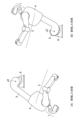
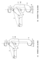
- FIG. 4 is an explanatory diagram relating to the operation of rotating the structure above the connecting portion around the yaw axis (J1).
- FIG. 5 is an explanatory diagram relating to the operation of swinging the structure above the guide portion about the pitch axis (J2).
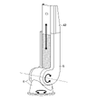
- FIG. 6 is an explanatory diagram of a connecting mechanism between the connecting portion and the guide portion.
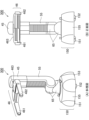
- FIG. 7 is an explanatory diagram relating to the up-and-down motion along the drive shaft (J3) of the structure above the trunk connecting member.
- FIG. 8 is an explanatory diagram showing the detailed structure between the trunk connecting member and the guide rail.
- FIG. 9 is an explanatory diagram showing a posture in which the robot is tilted forward by 90 degrees.
- FIG. 10 is an external perspective view (modification) of a robot equipped with a full mobile carriage.
- FIG. 11 is an explanatory diagram (modification) of a robot having a gripper.
- FIG. 1 is an external perspective view (Part 1) of the robot 100 according to this embodiment.
- the robot 100 includes a head 1 and a substantially rectangular body 4 that supports the head 1 and two arms (a right arm 2 and a left arm 3) extending from the left and right.
- the trunk portion 4 is configured to be able to move up and down (or expand and contract) along a guide rail corresponding to the long side of the substantially J-shaped guide portion 5 .
- a lower end of the guide portion 5 is coupled to the crawler 8 via a connecting portion 6 .
- the robot 100 has a reference movement direction, and in the figure, the robot 100 faces the reference movement direction.
- the reference moving direction of the robot 100 is referred to as forward, and the opposite direction as backward. is sometimes referred to as the bottom, and the vertically upward direction is sometimes referred to as the top.
- each drive axis which will be described later, is driven by a control mechanism and a drive mechanism (not shown) provided in the robot 100 . Further, a power supply system (not shown) is arranged in the robot 100 .
- the head 1 is equipped with a sensor such as a camera, and is configured to be able to recognize the surrounding situation.
- the head 1 is configured to rotate around a drive shaft extending vertically from the vicinity of the center of the top surface of the body 4 and around a drive shaft in the shoulder width direction orthogonal thereto. That is, the head 1 has two degrees of freedom and can be observed vertically and horizontally.
- the right arm 2 and left arm 3 are articulated robot arms each having 7 degrees of freedom.
- the body portion 4 is configured to move linearly along the guide rails of the guide portion 5 .
- FIG. 1 shows a state in which the body portion 4 is arranged at the highest position (upper limit) with respect to the guide rail.
- FIG. 2 is an external perspective view (part 2) of the robot 100.
- drum 4 is arrange
- the trunk portion 4 can be linearly moved from the connecting portion 6 coupled to one end of the guide portion 5 to the other end.
- the robot 100 if the robot 100 is tilted in any direction, it can be accessed using a manipulator in the front-back direction.
- the crawler 8 has a base portion 82 having an oval vertical cross section, and a right belt 81 and a left belt 83 arranged on both left and right side surfaces of the base portion 82 and independently driven to rotate.
- the top surface of the base portion 82 is planar, and the connecting portion 6 is located on the top surface of the base portion 82 in an area (behind the center) that is closer to the direction opposite to the reference movement direction than the center of the top surface. ) are combined in
- the center of the top surface of the base portion 82 or the area near the reference movement direction can be used as an area for placing an object manipulated by the manipulators 2 and 3 .
- the torso 4 of the robot 100 is swung in the reference movement direction, it is possible to prevent overturning due to movement of the center of gravity.
- the connecting part 6 has two upper and lower connecting mechanisms. Used.
- the connecting mechanism in the lower part of the connecting part 6 is connected to the base part 82 so as to be able to turn around the drive shaft (J1, see FIG. 3) extending vertically upward from the base part 82 .
- the cross section of the top surface of the base portion 82 at the lower portion of the connecting portion 6 is circular.
- connection part 6 is connected to the lower end of the guide part 5 so as to be rotatable around the drive shaft (J2, see FIG. 3) extending in the left and right direction of the robot 100. That is, the guide portion 5 can be swung back and forth by the rotation about the drive shaft.
- FIG. 3 is an explanatory diagram regarding the arrangement of the drive shafts of the robot 100 according to this embodiment.
- the figure shows a schematic configuration of the base portion 82, the connecting portion 6, the guide portion 5, and the trunk portion connecting member 42 in order from the bottom in the drawing.
- the trunk connecting member 42 is arranged inside the trunk 4 and moves together with the trunk 4 .
- the connecting portion 6 is coupled to the top surface of the base portion 82 so as to be rotatable around the drive shaft (J1) extending vertically upward from the base portion 82 .
- This driving shaft (J1) can rotate the components above the connecting part 6 (connecting part 6, guide part 5, body part 4, head part 1, right arm part 2, left arm part 3).
- the connecting portion 6 extends the lower end of the guide portion 5 and the components above the guide portion 5 (the guide portion 5, the body portion 4, the head portion 1, the right arm portion 2, and the left arm portion 3) perpendicular to the drive shaft (J1). They are connected in a manner to swing around a driving shaft (J2) extending to the left and right of the robot 100. As shown in FIG.
- the drive shaft (J2) allows the components above the guide portion 5 to swing with respect to the connecting portion 6. As shown in FIG.
- trunk connecting member 42 is coupled with the guide rail in a manner that allows linear movement along the longitudinal axis (J3) of the guide rail.
- This drive shaft (J3) can linearly move the components above the body connecting part 42 (body connecting part 42, body 4, head 1, right arm 2, left arm 3).
- the drive axis (J1) may be called the yaw axis
- the drive axis (J2) may be called the pitch axis.
- the yaw axis (J1) is orthogonal to the pitch axis (J2).
- the pitch axis (J2) is also perpendicular to the longitudinal axis (J3) of the guide rail.
- FIG. 4 is an explanatory diagram relating to the operation of rotating the structure above the connecting portion 6 around the yaw axis (J1).
- FIG. 4(A) depicts a state in which the components including the connecting portion 6 and above are turned 90° to the right around the yaw axis (J1).
- FIG. 5 is an explanatory diagram relating to the operation of swinging the configuration above the guide section 5 around the pitch axis (J2).
- the configuration above the guide section 5 can be freely swung as long as it does not collide with the base section 82 .
- the configuration above the guide section 5 can be freely swung as long as it does not collide with the base section 82 .
- the configuration above the guide section 5 can be freely swung as long as it does not collide with the base section 82 .
- the configuration above the guide section 5 can be freely swung as long as it does not collide with the base section 82 .
- FIG. It can also be tilted backwards.
- FIG. 6 is an explanatory diagram of a connecting mechanism between the connecting portion 6 and the guide portion 5.
- FIG. 1A is a perspective view of an actual coupling mechanism
- FIG. 1B is a schematic diagram thereof.
- the lower end of the guide portion 5 is coupled to the connecting portion 6 so as to sandwich the upper portion of the connecting portion 6 from both sides. That is, the connecting portion 6 and the lower end of the guide portion 5 are coupled by a so-called double-support structure.
- FIG. 7 is an explanatory diagram relating to the up-and-down movement along the drive shaft (J3) of the body part connecting member 42 and above.
- FIG. 4A shows a case where the trunk connecting member 42 is arranged at the upper end (upper limit).
- a motor 41 and a trunk connecting member 42 are arranged inside the hollow housing of the trunk 4 of the robot 100 (see broken lines in the figure).
- (B) shows a case where the trunk connecting member 42 is arranged at the lower end (lower limit).
- the guide rail is contained in the body portion 4 and does not protrude from the upper end.
- FIG. 8 is an explanatory diagram showing the detailed structure between the trunk connecting member 42 and the guide rail.
- a guide rail corresponding to the long side of the substantially J-shaped guide portion 5 is drawn in the center of the figure.
- the trunk connecting member 42 slides while being engaged with the guide rails, whereby the trunk 4 that is attached to the trunk connecting member 42 and moves integrally moves up and down.
- FIG. 9 is an explanatory diagram showing the forward tilting posture of the robot 100 in which the configuration of the guide section 5 and above is swung forward by 90° around the pitch axis (J2) from the upright state. At this time, the guide rail is parallel to the top surface of the base portion 82 .
- a predetermined distance (offset) d is provided between the body portion 4 and the base portion 82 even when rocked by 90°.
- the robot 100 it is possible to provide the robot 100 with a wide work area that can be accessed in all three-dimensional directions by the manipulator.
- the robot 100 can move freely using the mobile body and can access the destination in all three-dimensional directions with high accuracy without moving the mobile body. can provide.
- the crawler 8 was adopted as the transition mechanism.
- the invention is not limited to such configurations. Therefore, another moving mechanism, such as an omnidirectional mobile trolley, may be employed.
- FIG. 10 is an external perspective view of the robot 200 equipped with an omnidirectional mobile cart.
- the configuration of the connecting portion 6 and above is the same as that shown in the above-described embodiment, so the description thereof is omitted.
- the robot 200 is equipped with an omnidirectional mobile cart 9 instead of the crawler 8 .
- the omnidirectional mobile carriage 9 includes a base portion 95 having a substantially circular horizontal cross section, and drive wheels 91 to 94 (94 is not shown) provided on the four sides of the bottom surface of the base portion 95 .
- a pair of arms are used as manipulators.
- the invention is not limited to such configurations. Accordingly, other manipulators, such as grippers, may be employed.
- FIG. 11 is an explanatory diagram of a robot 300 equipped with an omnidirectional mobile cart as a movement mechanism and a gripper 46 as a manipulator.
- 1A is an external perspective view of the robot 300
- FIG. 1B is a front view of the robot 300.
- the top surface of the omnidirectional mobile carriage 150 is provided with a connecting portion 65 that rotates around the yaw axis (J1) as in the first embodiment.
- the upper portion of the connecting portion 65 is connected to the lower end of the substantially J-shaped guide portion 55 so as to be rotatable about the pitch axis (J2).
- a slide member 45 is attached to a guide rail corresponding to the long side of the J-shaped guide portion 55 so as to move up and down along the guide rail.
- a gripper 46 is attached to the front surface of the slide member 45 .
- the gripper 46 has a support portion 463 that supports a pair of holding plates 461 and 462 .
- An object can be gripped by opening and closing the clamping plates 461 and 462 .
- the present invention can be used in industries that manufacture robots.
Landscapes
- Engineering & Computer Science (AREA)
- Robotics (AREA)
- Mechanical Engineering (AREA)
- Manipulator (AREA)
Priority Applications (2)
| Application Number | Priority Date | Filing Date | Title |
|---|---|---|---|
| PCT/JP2021/032717 WO2023032217A1 (ja) | 2021-09-06 | 2021-09-06 | ロボット及びロボットシステム |
| JP2023544991A JP7776515B2 (ja) | 2021-09-06 | 2021-09-06 | ロボット及びロボットシステム |
Applications Claiming Priority (1)
| Application Number | Priority Date | Filing Date | Title |
|---|---|---|---|
| PCT/JP2021/032717 WO2023032217A1 (ja) | 2021-09-06 | 2021-09-06 | ロボット及びロボットシステム |
Publications (1)
| Publication Number | Publication Date |
|---|---|
| WO2023032217A1 true WO2023032217A1 (ja) | 2023-03-09 |
Family
ID=85411683
Family Applications (1)
| Application Number | Title | Priority Date | Filing Date |
|---|---|---|---|
| PCT/JP2021/032717 Ceased WO2023032217A1 (ja) | 2021-09-06 | 2021-09-06 | ロボット及びロボットシステム |
Country Status (2)
| Country | Link |
|---|---|
| JP (1) | JP7776515B2 (https=) |
| WO (1) | WO2023032217A1 (https=) |
Cited By (1)
| Publication number | Priority date | Publication date | Assignee | Title |
|---|---|---|---|---|
| CN119427307A (zh) * | 2024-11-08 | 2025-02-14 | 南方科技大学 | 一种用于行李车收集的双臂机器人及收集方法 |
Citations (4)
| Publication number | Priority date | Publication date | Assignee | Title |
|---|---|---|---|---|
| JPS60217082A (ja) * | 1984-04-13 | 1985-10-30 | 株式会社東芝 | 作業用ロボツト装置 |
| JP2006202213A (ja) * | 2005-01-24 | 2006-08-03 | Yaskawa Electric Corp | 全方向移動ロボット |
| JP2019206038A (ja) * | 2016-09-30 | 2019-12-05 | ライフロボティクス株式会社 | ロボットアーム機構 |
| WO2021130929A1 (ja) * | 2019-12-25 | 2021-07-01 | 東京ロボティクス株式会社 | ロボット、システム、方法及びプログラム |
Family Cites Families (1)
| Publication number | Priority date | Publication date | Assignee | Title |
|---|---|---|---|---|
| JPS60141485A (ja) * | 1983-12-29 | 1985-07-26 | フアナツク株式会社 | 作業用複合ロボツト装置 |
-
2021
- 2021-09-06 WO PCT/JP2021/032717 patent/WO2023032217A1/ja not_active Ceased
- 2021-09-06 JP JP2023544991A patent/JP7776515B2/ja active Active
Patent Citations (4)
| Publication number | Priority date | Publication date | Assignee | Title |
|---|---|---|---|---|
| JPS60217082A (ja) * | 1984-04-13 | 1985-10-30 | 株式会社東芝 | 作業用ロボツト装置 |
| JP2006202213A (ja) * | 2005-01-24 | 2006-08-03 | Yaskawa Electric Corp | 全方向移動ロボット |
| JP2019206038A (ja) * | 2016-09-30 | 2019-12-05 | ライフロボティクス株式会社 | ロボットアーム機構 |
| WO2021130929A1 (ja) * | 2019-12-25 | 2021-07-01 | 東京ロボティクス株式会社 | ロボット、システム、方法及びプログラム |
Cited By (1)
| Publication number | Priority date | Publication date | Assignee | Title |
|---|---|---|---|---|
| CN119427307A (zh) * | 2024-11-08 | 2025-02-14 | 南方科技大学 | 一种用于行李车收集的双臂机器人及收集方法 |
Also Published As
| Publication number | Publication date |
|---|---|
| JP7776515B2 (ja) | 2025-11-26 |
| JPWO2023032217A1 (https=) | 2023-03-09 |
Similar Documents
| Publication | Publication Date | Title |
|---|---|---|
| US8661926B2 (en) | Robot manipulator and robot system | |
| JP5499647B2 (ja) | ロボット及びロボットシステム | |
| JP6677190B2 (ja) | 塗装システムおよび固定式操作ロボット | |
| CN101454125A (zh) | 工件输送系统 | |
| US20160031095A1 (en) | Robot | |
| CN108621128B (zh) | 一种大范围定位及姿态灵活调整的移动式加工机器人 | |
| US20160031094A1 (en) | Robot | |
| CN108621114A (zh) | 一种面向大型结构件加工的移动式机器人 | |
| WO2019009290A1 (ja) | ロボットシステム及び包装システム | |
| WO2023032217A1 (ja) | ロボット及びロボットシステム | |
| US20210008710A1 (en) | Mobile robot | |
| JP2007118176A (ja) | 移動型マニピュレータ | |
| CN107901029B (zh) | 六轴并联机构及机器人 | |
| US20230311333A1 (en) | Painting robot and painting system | |
| JP2023170088A (ja) | ロボット、把持装置、方法、プログラム及びシステム | |
| CN113001516B (zh) | 一种过约束两栖机器人 | |
| US20240342930A1 (en) | Vertical articulated robot | |
| JP2620503B2 (ja) | 産業用マニプレータ | |
| JP2024061082A (ja) | ロボットシステムおよびロボットの駆動方法 | |
| JP2023111483A (ja) | グリッパ及びグリッパを備えたロボット | |
| JPH05337851A (ja) | アーム旋回式ロボット | |
| WO2024053204A1 (ja) | モバイルマニピュレータ及びその制御方法、プログラム | |
| JP2006187815A (ja) | マニピュレータ及びこれを用いた搬送ロボット | |
| JP7802555B2 (ja) | グリッパ及びロボット | |
| US20250018902A1 (en) | Overturn prevention device and conveyance device |
Legal Events
| Date | Code | Title | Description |
|---|---|---|---|
| 121 | Ep: the epo has been informed by wipo that ep was designated in this application |
Ref document number: 21956102 Country of ref document: EP Kind code of ref document: A1 |
|
| WWE | Wipo information: entry into national phase |
Ref document number: 2023544991 Country of ref document: JP |
|
| NENP | Non-entry into the national phase |
Ref country code: DE |
|
| 122 | Ep: pct application non-entry in european phase |
Ref document number: 21956102 Country of ref document: EP Kind code of ref document: A1 |