WO2023026862A1 - パターン入り液体の製造方法及びパターン入り液体の製造システム - Google Patents
パターン入り液体の製造方法及びパターン入り液体の製造システム Download PDFInfo
- Publication number
- WO2023026862A1 WO2023026862A1 PCT/JP2022/030519 JP2022030519W WO2023026862A1 WO 2023026862 A1 WO2023026862 A1 WO 2023026862A1 JP 2022030519 W JP2022030519 W JP 2022030519W WO 2023026862 A1 WO2023026862 A1 WO 2023026862A1
- Authority
- WO
- WIPO (PCT)
- Prior art keywords
- liquid
- microparticles
- nozzle
- pattern
- patterned
- Prior art date
- Legal status (The legal status is an assumption and is not a legal conclusion. Google has not performed a legal analysis and makes no representation as to the accuracy of the status listed.)
- Ceased
Links
Images




Classifications
-
- A—HUMAN NECESSITIES
- A23—FOODS OR FOODSTUFFS; TREATMENT THEREOF, NOT COVERED BY OTHER CLASSES
- A23L—FOODS, FOODSTUFFS OR NON-ALCOHOLIC BEVERAGES, NOT OTHERWISE PROVIDED FOR; PREPARATION OR TREATMENT THEREOF
- A23L2/00—Non-alcoholic beverages; Dry compositions or concentrates therefor; Preparation or treatment thereof
-
- A—HUMAN NECESSITIES
- A23—FOODS OR FOODSTUFFS; TREATMENT THEREOF, NOT COVERED BY OTHER CLASSES
- A23P—SHAPING OR WORKING OF FOODSTUFFS, NOT FULLY COVERED BY A SINGLE OTHER SUBCLASS
- A23P10/00—Shaping or working of foodstuffs characterised by the products
-
- A—HUMAN NECESSITIES
- A23—FOODS OR FOODSTUFFS; TREATMENT THEREOF, NOT COVERED BY OTHER CLASSES
- A23L—FOODS, FOODSTUFFS OR NON-ALCOHOLIC BEVERAGES, NOT OTHERWISE PROVIDED FOR; PREPARATION OR TREATMENT THEREOF
- A23L2/00—Non-alcoholic beverages; Dry compositions or concentrates therefor; Preparation or treatment thereof
- A23L2/38—Other non-alcoholic beverages
-
- A—HUMAN NECESSITIES
- A23—FOODS OR FOODSTUFFS; TREATMENT THEREOF, NOT COVERED BY OTHER CLASSES
- A23L—FOODS, FOODSTUFFS OR NON-ALCOHOLIC BEVERAGES, NOT OTHERWISE PROVIDED FOR; PREPARATION OR TREATMENT THEREOF
- A23L2/00—Non-alcoholic beverages; Dry compositions or concentrates therefor; Preparation or treatment thereof
- A23L2/52—Adding ingredients
-
- A—HUMAN NECESSITIES
- A23—FOODS OR FOODSTUFFS; TREATMENT THEREOF, NOT COVERED BY OTHER CLASSES
- A23P—SHAPING OR WORKING OF FOODSTUFFS, NOT FULLY COVERED BY A SINGLE OTHER SUBCLASS
- A23P20/00—Coating of foodstuffs; Coatings therefor; Making laminated, multi-layered, stuffed or hollow foodstuffs
-
- A—HUMAN NECESSITIES
- A23—FOODS OR FOODSTUFFS; TREATMENT THEREOF, NOT COVERED BY OTHER CLASSES
- A23P—SHAPING OR WORKING OF FOODSTUFFS, NOT FULLY COVERED BY A SINGLE OTHER SUBCLASS
- A23P30/00—Shaping or working of foodstuffs characterised by the process or apparatus
-
- B—PERFORMING OPERATIONS; TRANSPORTING
- B33—ADDITIVE MANUFACTURING TECHNOLOGY
- B33Y—ADDITIVE MANUFACTURING, i.e. MANUFACTURING OF THREE-DIMENSIONAL [3D] OBJECTS BY ADDITIVE DEPOSITION, ADDITIVE AGGLOMERATION OR ADDITIVE LAYERING, e.g. BY 3D PRINTING, STEREOLITHOGRAPHY OR SELECTIVE LASER SINTERING
- B33Y10/00—Processes of additive manufacturing
-
- B—PERFORMING OPERATIONS; TRANSPORTING
- B33—ADDITIVE MANUFACTURING TECHNOLOGY
- B33Y—ADDITIVE MANUFACTURING, i.e. MANUFACTURING OF THREE-DIMENSIONAL [3D] OBJECTS BY ADDITIVE DEPOSITION, ADDITIVE AGGLOMERATION OR ADDITIVE LAYERING, e.g. BY 3D PRINTING, STEREOLITHOGRAPHY OR SELECTIVE LASER SINTERING
- B33Y30/00—Apparatus for additive manufacturing; Details thereof or accessories therefor
-
- B—PERFORMING OPERATIONS; TRANSPORTING
- B33—ADDITIVE MANUFACTURING TECHNOLOGY
- B33Y—ADDITIVE MANUFACTURING, i.e. MANUFACTURING OF THREE-DIMENSIONAL [3D] OBJECTS BY ADDITIVE DEPOSITION, ADDITIVE AGGLOMERATION OR ADDITIVE LAYERING, e.g. BY 3D PRINTING, STEREOLITHOGRAPHY OR SELECTIVE LASER SINTERING
- B33Y70/00—Materials specially adapted for additive manufacturing
-
- A—HUMAN NECESSITIES
- A23—FOODS OR FOODSTUFFS; TREATMENT THEREOF, NOT COVERED BY OTHER CLASSES
- A23P—SHAPING OR WORKING OF FOODSTUFFS, NOT FULLY COVERED BY A SINGLE OTHER SUBCLASS
- A23P20/00—Coating of foodstuffs; Coatings therefor; Making laminated, multi-layered, stuffed or hollow foodstuffs
- A23P20/20—Making of laminated, multi-layered, stuffed or hollow foodstuffs, e.g. by wrapping in preformed edible dough sheets or in edible food containers
- A23P20/25—Filling or stuffing cored food pieces, e.g. combined with coring or making cavities
- A23P2020/253—Coating food items by printing onto them; Printing layers of food products
Definitions
- the present invention relates to a patterned liquid manufacturing method and a patterned liquid manufacturing system. More specifically, the present invention relates to a patterned liquid manufacturing method and a patterned liquid manufacturing system capable of forming patterns such as characters, pictures, and component bias in the liquid.
- the three-dimensional printing technology is a technology for forming a three-dimensional structure by sequentially laminating materials as two-dimensional layers based on three-dimensional CAD (Computer-Aided Design) data. Using this technology, three-dimensional structures have been formed from various materials such as metals, polymers, food materials, and cells.
- Another object of the present invention is to provide a low-environmental-load plant-based beverage that has a texture equivalent to that of real milk, coffee, or other environmentally-friendly beverages by designing patterns at the micro level.
- the present inventors focused on using micro-sized edible microparticles for pattern generation in the liquid.
- Such edible microparticles are usually used for the purpose of making the ingredients easily ingestible or available together with the liquid by including the insoluble ingredients and uniformly dispersing them in the liquid.
- the present inventors have found that if the size-dependent diffusion phenomenon of edible microparticles is used, the microparticles will remain in place for a certain period of time even in the liquid. It has been found that by arranging particles, a pattern such as a character or a picture made of microparticles can be drawn and the shape can be maintained. This is because microparticles have a smaller diffusion coefficient than low molecules such as pigments.
- the present invention relates to the following patterned liquid manufacturing method and patterned liquid manufacturing system.
- a pattern-forming material in which micro-sized first microparticles containing a first edible organic substance are dispersed in a first liquid is transferred to a second edible organic substance using a position-controllable nozzle.
- ⁇ 3> The above ⁇ 1> or ⁇ 2>, wherein the first microparticles and/or the second microparticles are aggregated by non-covalent cohesion and produce a texture. 3.
- a method for producing a patterned liquid according to . ⁇ 4> The method for producing a patterned liquid according to any one of ⁇ 1> to ⁇ 3> above, wherein the first and/or second microparticles have a diameter of 0.13 ⁇ m or more and 1000 ⁇ m or less.
- ⁇ 5> The ratio of each density of the first and second microparticles to the density of the second liquid is 0.9 or more and 1.1 or less, and the second microparticle to the density of the first liquid is 0.9 or more and 1.1 or less.
- ⁇ 6> The pattern according to any one of ⁇ 1> to ⁇ 5> above, wherein the absolute value of the difference in water content between the first liquid and the second liquid is 0% or more and 50% or less.
- ⁇ 7> Any one of ⁇ 1> to ⁇ 6> above, wherein the viscosity of the first liquid and the viscosity of the second liquid are respectively 0.8 mPa ⁇ s or more and 6 Pa ⁇ s or less at 25°C. 3.
- a method for producing a patterned liquid according to . ⁇ 8> The above ⁇ 1> to ⁇ 7>, wherein the diameter L of the nozzle and the velocity U of the nozzle in the second liquid satisfy the relationship U ⁇ L ⁇ 10 ⁇ 3 m 2 /s.
- a method for producing a patterned liquid according to any one of the above. ⁇ 9> The ratio of the value obtained by dividing the ejection flow rate X of the pattern forming material ejected from the nozzle by the opening area A of the tip of the nozzle to the speed U of the nozzle in the second liquid is 0. .2 or more and 10 or less, the method for producing a patterned liquid according to any one of the above ⁇ 1> to ⁇ 8>.
- a system for producing a patterned liquid in which a pattern is formed in the liquid comprising: a tank containing a pattern-forming material in which micro-sized microparticles containing an edible organic substance are dispersed in a first liquid; , a nozzle for discharging the pattern forming material, a pump for feeding the pattern forming material to the nozzle, a position of the nozzle, and a discharge flow rate of the pattern forming material discharged from the nozzle; and a control device that controls the diameter L of the nozzle and the speed U of the nozzle to satisfy the relationship U ⁇ L ⁇ 10 ⁇ 3 m 2 /s in the second liquid.
- a manufacturing system for a patterned liquid wherein the pattern forming material is discharged from the nozzle while moving the nozzle.
- a pattern-forming material in which micro-sized first microparticles containing a first edible organic substance are dispersed in a first liquid is poured into a second liquid using a position-controllable nozzle.
- a method for producing a patterned liquid comprising ejecting to form a pattern of the first microparticles.
- the first edible organic substance is at least one selected from the group consisting of polysaccharides, polypeptides, higher alcohols, natural resins, lipids, higher fatty acid esters, polyphenols, polyvinyl alcohols, polyethylene glycols, and nucleic acids.
- the method for producing a patterned liquid according to any one of the above [1] to [6], which is an edible organic substance of [8] The patterned liquid according to any one of [1] to [7] above, wherein the first microparticles are aggregated by non-covalent cohesion and produce a texture. Production method. [9] The pattern according to any one of [1] to [8] above, wherein the absolute value of the difference in water content between the first liquid and the second liquid is 0% or more and 50% or less.
- a method of manufacturing an infused liquid is a method of manufacturing an infused liquid.
- the ratio of the value obtained by dividing the ejection flow rate X of the pattern forming material ejected from the nozzle by the opening area A of the tip of the nozzle to the velocity U of the nozzle in the second liquid is 0. .2 or more and 10 or less;
- Micro-sized second microparticles containing a second edible organic substance are dispersed in the second liquid, and the second liquid in which the second microparticles are dispersed contains the above
- the ratio of the density of the second microparticles to each of the density of the first microparticles, the density of the first liquid, and the density of the second liquid is 0.9 or more and 1.1.
- the second edible organic substance is at least one selected from the group consisting of polysaccharides, polypeptides, higher alcohols, natural resins, lipids, higher fatty acid esters, polyphenols, polyvinyl alcohols, polyethylene glycols, and nucleic acids.
- the method for producing a patterned liquid according to any one of [17] to [22] above, which contains an edible organic substance of [24] The patterned liquid according to any one of [17] to [23] above, wherein the second microparticles are aggregated by non-covalent cohesiveness and produce a texture. Production method.
- a system for producing a patterned liquid in which a pattern is formed in the liquid the tank containing a pattern-forming material in which micro-sized microparticles containing an edible organic substance are dispersed in a first liquid; , a nozzle for discharging the pattern forming material, a pump for feeding the pattern forming material to the nozzle, a position of the nozzle, and a discharge flow rate of the pattern forming material discharged from the nozzle. and a control device that controls the diameter L of the nozzle and the speed U of the nozzle to satisfy the relationship U ⁇ L ⁇ 10 ⁇ 3 m 2 /s in the second liquid.
- a patterned liquid manufacturing system wherein the pattern forming material is ejected from the nozzle while moving the nozzle.
- the ratio of the value obtained by dividing the ejection flow rate X of the pattern forming material ejected from the nozzle by the opening area A of the tip of the nozzle to the velocity U of the nozzle in the second liquid is 0. 2 or more and 10 or less, the manufacturing system of the patterned liquid according to the above [25].
- a position-controllable nozzle a first liquid is discharged into a second liquid in which micro-sized microparticles containing an edible organic substance are dispersed to form a pattern composed of the first liquid.
- a patterned liquid manufacturing system in which a pattern is formed in the liquid comprising: a tank containing a first liquid; a nozzle for discharging the first liquid; and a control device for controlling the position of the nozzle and the discharge flow rate of the first liquid discharged from the nozzle, wherein the control device controls the diameter L of the nozzle and the While moving the nozzle in the second liquid in which micro-sized microparticles containing edible organic matter are dispersed, such that the velocity U of the nozzle satisfies the relationship of U ⁇ L ⁇ 10 ⁇ 3 m 2 /s
- a patterned liquid manufacturing system that ejects the first liquid from the nozzles.
- the ratio of the value obtained by dividing the discharge flow rate X of the first liquid discharged from the nozzle by the opening area A of the tip of the nozzle to the velocity U of the nozzle in the second liquid is 0. 2 or more and 10 or less, the manufacturing system of the patterned liquid according to the above [28].
- a patterned liquid production method and a patterned liquid production system with a high degree of design freedom in a patterned liquid that can produce sensations such as color, taste, texture, and tactile sensation. can.
- FIG. 1 is a graph showing theoretical values of the relationship between the amount typically migrated per hour by a microparticle placed in a liquid and the diameter of the microparticle.
- FIG. 2 is a graph showing theoretical values in the range where the Reynolds number is 1000 or less when the nozzle is moved in the liquid.
- FIG. 3 is a conceptual diagram of a patterned liquid manufacturing system for forming a pattern in liquid according to the present invention.
- FIG. 4 is a conceptual diagram of a patterned liquid manufacturing system using a gantry type system according to the present invention.
- FIG. 5 is a conceptual diagram of a patterned liquid manufacturing system using a robot arm according to the present invention.
- FIG. 6 is an optical micrograph of a 10% by volume microparticle suspension in Verification Experiment 1.
- FIG. 7 is a photograph in which a microparticle suspension with a diameter of 1 ⁇ m was dropped into a 20% by volume glycerol aqueous solution in verification experiment 2.
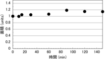
- FIG. 8 is a graph showing the diffusion of microparticle suspensions with a diameter of 1 ⁇ m when various liquid volumes were dropped into a 20 vol % glycerol aqueous solution in Verification Experiment 3.
- FIG. 9 is a graph showing the diffusion when a suspension of microparticles with a diameter of 1 ⁇ m was dropped into a 20 vol% glycerol aqueous solution at a concentration of 0.5 vol% and a liquid volume of 0.5 ⁇ L in verification experiment 3, and left for 4 hours. is.
- FIG. 8 is a graph showing the diffusion of microparticle suspensions with a diameter of 1 ⁇ m when various liquid volumes were dropped into a 20 vol % glycerol aqueous solution in Verification Experiment 3.
- FIG. 9 is a graph showing the diffusion when
- FIG. 10 is a graph showing the diffusion of a suspension of microparticles with a diameter of 0.2 ⁇ m when dropped into a 20 vol % glycerol aqueous solution in Verification Experiment 4.
- FIG. FIG. 11 is a photograph of a microparticle suspension with a diameter of 1 ⁇ m in a 20 vol % aqueous glycerol solution constructed in verification experiment 5.
- FIG. 12 shows the diffusion of microparticle suspensions with a diameter of 45 ⁇ m or 90 ⁇ m in a concentration of 1.4% by volume in a 20% by volume aqueous solution of glycerol in verification experiment 6 at a volume of 1 ⁇ L, and allowed to stand for 4 hours. It is a graph showing.
- FIG. 11 is a photograph of a microparticle suspension with a diameter of 1 ⁇ m in a 20 vol % aqueous glycerol solution constructed in verification experiment 5.
- FIG. 12 shows the diffusion of microparticle suspensions with a diameter of 45
- FIG. 13 is a photograph of dropping a 1% by weight uranin solution into a 20% by volume glycerol aqueous solution.
- 14 is an optical micrograph of the agarose microparticle suspension in Verification Experiment 7.
- FIG. 15 is a graph showing diffusion when an agarose microparticle suspension with a diameter of 90 ⁇ m was dropped into a 20 vol % glycerol aqueous solution in Verification Experiment 7 and allowed to stand for 4 hours.
- FIG. 16 is a graph showing diffusion when a 1% by weight uranin solution is dropped into a 20% by volume glycerol aqueous solution and allowed to stand for 3 minutes.
- FIG. 17 shows various suspensions containing microparticles with a diameter of 1 ⁇ m at a concentration of 0.2% by volume in a 20% by volume glycerol aqueous solution containing 0.5% by weight or 1% by weight of carboxymethyl cellulose in verification experiment 8.
- FIG. 10 is a graph showing the results of evaluation of deviation of a line of 40 mm in length when ink is drawn with a nozzle diameter, movement speed, and discharge flow rate.
- FIG. FIG. 18 shows that in verification experiment 9, a suspension containing microparticles with a diameter of 1 ⁇ m at a concentration of 0.2% by volume in a 20% by volume glycerol aqueous solution containing 0.5% by weight of carboxymethyl cellulose was ejected at various ejection flow rates.
- the method for producing a patterned liquid according to the first aspect of the present invention comprises first micro-sized micro-particles containing a first edible organic substance.
- a pattern-forming material in which particles are dispersed in a first liquid is ejected into a second liquid using a position-controllable nozzle to form a pattern of the first microparticles.
- the pattern-forming material in which the micro-sized first microparticles containing the first edible organic substance are dispersed in the first liquid is passed through the position-controllable nozzle. is ejected into the second liquid to form a pattern of the first microparticles, a pattern such as a character or a picture made of the first microparticles is formed in the second liquid serving as a field. It can be drawn and maintain its shape. Therefore, it is possible to provide a patterned liquid in which patterns such as color, taste, aroma, texture, and touch are freely designed.
- the first microparticles by incorporating a pigment, a taste-imparting substance, or an aroma component into the first microparticles, it is possible to design spatial colors, tastes, and aromas even in the second liquid. Also, by controlling the cohesiveness of the first microparticles, it is possible to design the spatial texture or tactile sensation in the second liquid. Furthermore, by designing the pattern of the first microparticles at the micro level, it is also possible to produce a plant-based beverage with a low environmental impact that has the same texture as real milk, coffee, or other beverages with a high environmental impact. It is possible.
- the “liquid” may be a liquid that can be ingested by drinking or that can be applied to the skin. Therefore, it is preferable that the first liquid and the second liquid are basically aqueous solutions.
- the types of the first liquid and the second liquid are not particularly limited, and include all beverages. Specifically, for example, water; tea; coffee; soft drinks such as fruit juice drinks, carbonated drinks, functional drinks, sports drinks, energy drinks, non-alcoholic drinks; alcoholic drinks; smoothies; frozen drinks; frozen cocktails; milkshakes;
- the second liquid preferably has such a degree of transparency that the pattern can be seen through the second liquid. From a similar point of view, the second liquid may be colored or colorless transparent.
- the first liquid and the second liquid may be different types of liquids, or may be the same type of liquid.
- first liquid and the second liquid may each be a single type of liquid, or may be a mixture or separation of a plurality of types of liquids.
- the types of the first liquid and the second liquid may be skin cosmetics such as perfume, lotion, and lotion.
- the types of the first liquid and the second liquid may be liquids suitable for cell growth and maintenance, such as medium and buffer solutions.
- the pattern may be a one-dimensional pattern (line), a two-dimensional pattern (plane), or a three-dimensional pattern (solid).
- the type of pattern is not particularly limited, and examples include those that produce colors such as characters and drawings, those that produce taste, texture, and tactile sensations such as biased ingredients, and those that produce these sensations in a complex manner.
- the first microparticles are micro-sized particles containing the first edible organic matter.
- the first microparticles are micro-sized particles, and preferably have a diameter of 0.13 ⁇ m or more as described later. It is limited and can stay near the ejected site for tens of minutes to tens of hours depending on its size. Therefore, it is possible to generate a patterned liquid in which the pattern of the first microparticles is arranged at arbitrary positions in the second liquid.
- the particle structure of the first microparticles is not particularly limited, and examples thereof include uniform type, core-shell type, and Janus type.
- the first microparticles are preferably insoluble or sparingly soluble in the first liquid and the second liquid (which may be water).
- the first microparticles can be stored for a long period of time while being dispersed in the first liquid, and the first microparticles can be maintained in the second liquid for a long period of time.
- the first microparticles constituting the pattern are not chemically bonded to each other by a crosslinker. This prevents the pattern of the first microparticles from agglomerating and makes it easier to drink the pattern with the second liquid.
- Equation 1 a typical moving distance x at a certain time t can be calculated from the diffusion coefficient D of the particles by Equation 1 below.
- x ⁇ (2Dt) (Formula 1)
- the diffusion coefficient D can be calculated from the Stokes-Einstein relationship (formula 2 below) using the particle diameter d, the Boltzmann constant k B , the absolute temperature T, and the viscosity ⁇ of the liquid constituting the system.
- D (k B T)/(3 ⁇ d) (Formula 2)
- the diffusion coefficient D is 4 ⁇ 10 ⁇ 13 m 2 /s, typically 1, where the viscosity of the liquid into which the particles are dropped is equivalent to that of water at 20° C. 50 ⁇ m per hour and 260 ⁇ m per 24 hours, respectively.
- FIG. 1 is a graph showing theoretical values of the relationship between the amount typically migrated per hour by a microparticle placed in a liquid and the diameter of the microparticle.
- FIG. 1 if the particle size is large, the diffusion due to Brownian motion is suppressed.
- the thickness of the line increases in one hour, assuming that the microparticles forming the lines diffuse three-dimensionally.
- the diameter of the microparticles thickened by 30% (0.3 mm) or more is 0.13 ⁇ m or less.
- the diameter of the microparticles thickened by 30% (0.3 mm) or more is 0.13 ⁇ m or less.
- the diameter of the microparticles thickened by 30% (0.3 mm) or more is 0.13 ⁇ m or less.
- two lines of a pattern forming material containing microparticles with a diameter of 0.13 ⁇ m and having a line width of 1 mm are arranged at an interval of 1 mm, even if the thickness of each line is increased by 1.3,
- the distance between the two lines is 0.3 mm, and it is possible to distinguish between the two lines. That is, by using microparticles with a diameter of 0.13 ⁇ m or more, it is possible to write a pattern that can be recognized even after one hour of writing.
- the diameter of the first microparticles may be 0.13 ⁇ m or more, but is preferably 0.2 ⁇ m or more and 1000 ⁇ m or less.
- the thickness is 0.2 ⁇ m or more, even if a pattern drawn with a line width of 1 mm is left in the second liquid for 1 hour, the pattern can be sufficiently maintained.
- it is 1000 ⁇ m or less, it is possible to avoid feeling a rough feeling when the first microparticles are put in the mouth (see, for example, Reference 1 below), and from this point of view, it is 100 ⁇ m or less. is more preferable.
- the diameter of the first microparticles is more preferably 0.3 ⁇ m or more, more preferably 0.5 ⁇ m or more, and even more preferably 50 ⁇ m or less.
- microparticle diameter is the mode diameter of the particle size distribution of the microparticles measured by the dynamic light scattering method (DLS).
- a ratio of the density of the first microparticles to the density of the second liquid is 0.9 or more and 1.1 or less
- the ratio of the density of the second liquid to the density of the first liquid is preferably 0.9 or more and 1.1 or less.
- these ratios are 0.9 or more and 1.1 or less, the pattern composed of the first microparticles is suppressed from floating or sinking in the second liquid together with the first liquid. can be done. From this point of view, these ratios are more preferably 0.92 or more and 1.08 or less, and further preferably 0.95 or more and 1.05 or less.
- microparticle density refers to microparticles (which may be pattern-forming materials) in solutions of various concentrations (e.g., aqueous glycerol solution).
- aqueous glycerol solution e.g., aqueous glycerol solution
- the solution is added dropwise and centrifuged under predetermined conditions (eg, 18,500 ⁇ g for 1 minute), and the density of the solution at which sedimentation of the microparticles is not observed shall be the lowest density.
- This solution and "liquid density” can be measured by, for example, a density meter (DMA 4500 M, manufactured by Anton Paar).
- the first microparticles preferably contain at least one component selected from the group consisting of pigments, taste components, nutrients and aroma components.
- the inclusion of these additives in the primary microparticles enables the design of various spatial sensations by patterns comprising the primary microparticles. For example, when a pigment is contained, a spatial color design is possible with a pattern of the first microparticles, and when a taste component is contained, a spatial taste design is possible with a pattern of the first microparticles.
- a spatial color design is possible with a pattern of the first microparticles
- a spatial taste design is possible with a pattern of the first microparticles.
- spatial nutrition design is possible by the pattern of the first microparticles
- aroma components when aroma components are included, spatial fragrance design is possible by the pattern of the first microparticles. becomes possible.
- a red pigment, a green pigment, a blue pigment, a black pigment, a white pigment, or the like may be used.
- taste components include sucrose, fructose, salt, glucose, amino acids, nucleic acids, acetic acid, malic acid, citric acid, caffeine, tannin, capsaicin, glycerol, and food extracts.
- Nutrients include, for example, vitamins, minerals, lipids, fatty acids, polypeptides, carbohydrates, health material molecules, and food extracts.
- the aroma component for example, food flavoring compounds including vanillin, eugenol, geraniol, citral, etc.
- the first microparticles may include a plurality of types of particles that differ in the presence or absence of pigments and the types of pigments contained (for example, different colors). The same is true for each of the taste component, the nutrient, and the aroma component, and the first microparticles may contain a plurality of types of particles differing in the presence or absence of these additives and the types of additives they contain.
- the first microparticles preferably include at least one of silica (silicon dioxide) and titania (titanium dioxide). By including these additives in the first microparticles, it is possible to express white and improve the development of other colors.
- the first microparticles may contain a hydrophobic or hydrophilic material to retain the above-mentioned additives such as dyes and silica within the microparticles.
- the first microparticle is a layer containing a hydrophobic substance, such as a three-layer structure of hydrophilic substance/hydrophobic substance/hydrophilic substance or hydrophobic substance/hydrophilic substance/hydrophobic substance. and a layer containing a hydrophilic substance are alternately arranged from the center toward the outside.
- the first microparticles include a first edible organic matter.
- the first edible organic substance is a substance that can function as a main component that forms the shape of the particles of the first microparticles.
- “edible organic matter” means organic matter that can be eaten by humans, but whether or not it can be digested by humans and whether or not it can be absorbed by humans are not particularly limited.
- the molecular weight of the first edible organic substance is not particularly limited, the first edible organic substance is preferably a high molecular weight substance.
- the first edible organic substance is at least one selected from the group consisting of polysaccharides, polypeptides, higher alcohols, natural resins, lipids, higher fatty acid esters, polyphenols, polyvinyl alcohols, polyethylene glycols, and nucleic acids (DNA).
- polysaccharide means a sugar in which multiple (two or more molecules) monosaccharides are bound.
- polypeptide means a compound in which a large number of amino acids are linked by peptide bonds, and includes proteins here.
- Preferred specific examples of the above polysaccharides include dextrin, pectin, agar, agarose, glucomannan, polydextrose, maltodextrin, alginic acid (sodium alginate, calcium alginate, etc.), cellulose, hemicellulose, chitin, chitosan, starch (starch, etc.). ), dextran, agarose, sucrose, methylcellulose, carboxymethylcellulose, hydroxypropylcellulose and the like. These can be used singly or in combination of two or more.
- Preferred specific examples of the above polypeptides include gelatin, protein hydrolysates, collagen, albumin and the like. These can be used singly or in combination of two or more.
- the higher alcohol include dodecyl alcohol and cetyl alcohol. These can be used singly or in combination of two or more.
- Preferred specific examples of the above natural resins include gum arabic, shellac, wax, lignin, polylactic acid and the like. These can be used singly or in combination of two or more.
- Preferred specific examples of the lipid include lecithin.
- polysaccharides and polypeptides can also be used in combination of two or more.
- first edible organic matter examples include those common to the specific examples of additives such as taste components and nutrients described above, and these common examples include taste components and nutrients. It is the first edible organic matter that can also function as a component of In this specification, the term "edible organic matter” is not limited to so-called foods and food additives, and may be pharmaceuticals, quasi-drugs, and the like, and means organic matter that can be taken orally.
- the first microparticles may be cells such as human-derived cells, animal cells, plant cells, and microbial cells. By using these cells as the first microparticles, it becomes possible to impart various physiological functions to the pattern composed of the first microparticles. These cells contain the first edible organic matter.
- the first microparticles are agglomerated by non-covalent cohesiveness, and may produce a texture or a tactile sensation. This makes it possible to design a spatial texture or tactile sensation based on the pattern of the first microparticles.
- the method of aggregating microparticles by non-covalent cohesion is not particularly limited, and for example, the microparticles may be agglomerated by charging the surface of the microparticles.
- the first microparticles are dispersed in the first liquid before being ejected into the second liquid, and are patterned using a position-controllable nozzle. It is discharged into the second liquid as a material for use.
- the first liquid constitutes a liquid containing the first microparticles so that the nozzle can be used to eject the first microparticles into the second liquid.
- the first microparticles contain a pigment component (when they exhibit color)
- the first liquid in which the first microparticles are dispersed that is, the pattern-forming material can function as a pattern-forming ink.
- the volume percent concentration of the first microparticles in the pattern forming material is not particularly limited, but is preferably 0.05% by volume or more and 50% by volume or less, and 0.1% by volume or more and 40% by volume. It is more preferably 0.5% by volume or more and 30% by volume or less.
- the volume percent concentration of the first microparticles in the pattern forming material can be measured by the Coulter counter method.
- the type of pattern forming material discharged into the second liquid is not particularly limited, and only one type of pattern forming material may be discharged into the second liquid. Two or more types of pattern forming materials different in at least one of the particles and the first liquid may be simultaneously or sequentially discharged into the second liquid.
- the first liquid is preferably compatible with the second liquid, and is the same as the second liquid. It may be a liquid, or a liquid close to a second liquid. This point will be described in detail below.
- the absolute value of the difference in water content between the first liquid and the second liquid is preferably 0% or more and 50% or less. By combining liquids that do not differ in water content, it is possible to change the taste and color without changing the texture or texture. By combining liquids with different water contents, it is possible to change the texture or tactile sensation.
- the absolute value of the difference between the two is more preferably 25% or less, more preferably 15% or less. Note that the water content of the first liquid is usually smaller than that of the second liquid.
- the "moisture content of the liquid” can be measured by the loss-on-drying method. That is, after measuring the weight of a sample containing water (liquid in this case), the sample is then placed in a constant temperature bath at a predetermined temperature to evaporate the water. You can measure quantity.
- the viscosity of the first liquid and the viscosity of the second liquid at 25° C. are preferably 0.8 mPa ⁇ s or more and 6 Pa ⁇ s or less, respectively. If the viscosities of both of them are 0.8 mPa s or more and 6 Pa s or less at 25° C., respectively, the diffusion of the first liquid into the second liquid is easily suppressed. shape can be maintained in the second liquid for a longer period of time. From this point of view, the viscosities of the two at 25° C. are more preferably 3 Pa ⁇ s or less, and more preferably 1 Pa ⁇ s or less.
- the viscosity of the first liquid and the viscosity of the second liquid are preferably 1 mPa s or more and 100 mPa s or less at 25° C., and 1 mPa s or more and 50 mPa s respectively. The following are more preferable. Either of the viscosity of the first liquid and the viscosity of the second liquid may be greater or may be substantially the same.
- the "viscosity of the liquid” is the density measured with a density meter (eg, DMA 4500 M, manufactured by Anton Paar) and a tuning fork vibration viscometer (eg, SV-10, manufactured by A&D ) can be used for measurement.
- a density meter eg, DMA 4500 M, manufactured by Anton Paar
- a tuning fork vibration viscometer eg, SV-10, manufactured by A&D
- the nozzle is a cylindrical body with a hollow inside and open at both ends, and the pattern forming material in which the first microparticles are dispersed in the first liquid is introduced from the proximal end of the nozzle into the nozzle. It flows through the cavity and is discharged from the tip of the nozzle.
- the three-dimensional position of the nozzle and the ejection flow rate of the pattern forming material ejected from the tip of the nozzle are usually controlled by a controller of the patterned liquid manufacturing system, which will be described later.
- the number of nozzles to be used is not particularly limited, and may be one or more.
- the nozzle is freely movable along multiple axes (for example, three axes or more and eight axes or less). As a result, a three-dimensional pattern can be easily formed as a pattern composed of the first microparticles. In addition to moving the nozzle, it is also possible to move the container containing the second liquid.
- the second liquid is contained in a container (eg, glass or cup), and the length of the nozzle is preferably longer than at least the depth of the second liquid contained in the container.
- the nozzle can be used to form a pattern of the first microparticles anywhere in the second liquid.
- the nozzles When forming a pattern in a liquid, the nozzles can create turbulence that disturbs the pattern. In general, turbulence is easier to suppress as the Reynolds number (Re) is smaller. It is particularly advantageous if it is kept below 1000.
- the following relationship between the nozzle diameter L and the nozzle speed U is the gray area in FIG.
- FIG. 2 shows theoretical values in the range where the Reynolds number is 1000 or less when the nozzle is moved in the liquid. That is, it is preferable that the diameter L (m) of the nozzle and the velocity U (m/s) of the nozzle in the second liquid satisfy the relationship U ⁇ L ⁇ 10 ⁇ 3 m 2 /s. . As a result, it is possible to effectively suppress the generation of turbulence caused by the nozzles, and to clearly form a pattern of a desired shape. From this point of view, the diameter L (m) of the nozzle and the velocity U (m/s) of the nozzle in the second liquid should be within the range of U ⁇ L ⁇ 5 ⁇ 10 ⁇ 4 m 2 /s. More preferably, it satisfies the relationship U ⁇ L ⁇ 10 ⁇ 4 m 2 /s.
- the "nozzle diameter L” means the length measured at the longest point of the opening at the tip of the nozzle.
- the opening shape of the tip of the nozzle is circular, it indicates the diameter, if it is elliptical, it indicates the length of the major axis, and if it is square, it indicates the length of the longer diagonal.
- the shape of the opening at the tip of the nozzle is V-shaped, U-shaped, C-shaped, or any other shape with a concave portion, it indicates the diameter of the smallest circle that can enclose the shape.
- the speed U (m/s) of the nozzle, the discharge flow rate X (m 3 /s) of the pattern forming material discharged from the nozzle, and the opening area A (m 2 ) of the tip of the nozzle are as follows.
- drawing is considered to be stable. This is because the relative velocity of the pattern forming material discharged with respect to the nozzle can be reduced, and the occurrence of turbulent flow due to the nozzle can be suppressed.
- U X/A (Formula 1)
- the velocity U (m/s) of the nozzles in the second liquid is , the ratio (X/A)/U ( hereinafter referred to as , also referred to as rate ratio) is preferably 0.2 or more and 10 or less, more preferably 0.3 or more and 8 or less, and even more preferably 0.4 or more and 5 or less.
- rate ratio preferably 0.2 or more and 10 or less, more preferably 0.3 or more and 8 or less, and even more preferably 0.4 or more and 5 or less.
- the opening shape of the tip of the nozzle is not particularly limited, but the nozzle preferably has a circular, elliptical, triangular, rectangular, square, rhomboid, V-shaped, U-shaped, or C-shaped tip.
- Microparticles may also be dispersed in the second liquid from which the pattern forming material is discharged. That is, micro-sized second microparticles containing a second edible organic substance are dispersed in the second liquid, and the pattern is dispersed in the second liquid in which the second microparticles are dispersed. A forming material may be ejected. On the other hand, microparticles may not be dispersed in the second liquid from which the pattern forming material is discharged. Thus, the pattern-forming material is discharged into the second liquid in which the micro-sized second microparticles containing the second edible organic substance are dispersed at 0% by volume or more and 74% by volume or less. .
- the volume percent concentration of the second microparticles in the second liquid is not particularly limited as long as it is 0% by volume or more and 74% by volume or less, but it is preferably 0.1% by volume or more and 70% by volume or less. It is preferably 1% by volume or more and 60% by volume or less, and even more preferably 5% by volume or more and 50% by volume or less. Note that the pattern formation in the liquid is not affected by the concentration of the microparticles in the liquid, so the concentration can be freely set.
- the structure when the same particles are most densely arranged in a liquid is a hexagonal close-packed structure, and the packing rate at that time can be calculated to be approximately 74% by volume. Therefore, the maximum volume percent concentration of the second microparticles in the second liquid is 74% by volume.
- volume percent concentration of the second microparticles in the second liquid can be measured by the Coulter counter method.
- the second microparticles are not chemically bonded with a crosslinker. This prevents the second microparticles from agglomerating and makes it easier to drink the second microparticles with the second liquid.
- the diameter of the second microparticles may be 0.13 ⁇ m or more, but is preferably 0.2 ⁇ m or more and 1000 ⁇ m or less, and 100 ⁇ m or less. is more preferable. Also, the diameter of the second microparticles is more preferably 0.3 ⁇ m or more, more preferably 0.5 ⁇ m or more, and even more preferably 50 ⁇ m or less.
- the second microparticles for the density of the first microparticles, the density of the first liquid and the density of the second liquid, respectively.
- Particle density ratios (second microparticle density/first microparticle density, second microparticle density/first liquid density, and second microparticle density/second The density of the liquid) is preferably 0.9 or more and 1.1 or less. Moreover, these ratios are more preferably 0.92 or more and 1.08 or less, and further preferably 0.95 or more and 1.05 or less.
- the second microparticles may contain at least one component selected from the group consisting of pigments, taste components, nutrients and aroma components. Specific examples of these components include those mentioned for the first microparticles.
- the second microparticles may include a plurality of types of particles that differ in the presence or absence of pigments and the types of pigments contained (for example, different colors). The same is true for each of taste components, nutrients, and aroma components, and the second microparticles may contain a plurality of types of particles differing in the presence or absence of these additives and the types of additives they contain.
- the second microparticles preferably contain at least one of silica and titania.
- the second microparticle may contain a hydrophobic or hydrophilic material to retain the above-mentioned additives such as dyes and silica within the microparticle.
- the second microparticles include a second edible organic matter.
- the second edible organic substance is a substance that can function as a main component that forms the shape of the second microparticle as a particle.
- the molecular weight of the second edible organic substance is not particularly limited, the second edible organic substance is preferably a high molecular weight substance.
- the second edible organic substance is at least one selected from the group consisting of polysaccharides, polypeptides, higher alcohols, natural resins, lipids, higher fatty acid esters, polyphenols, polyvinyl alcohols, polyethylene glycols, and nucleic acids (DNA). of edible organic matter.
- Preferred specific examples of these edible organic substances are those mentioned in the first edible organic substance.
- preferred specific examples of edible organic substances can be used in combination of one or more, and the above preferred organic substances belonging to different classes such as polysaccharides and polypeptides can be used in combination. Specific examples can also be used in combination of two or more.
- specific examples of edible organic substances may include specific examples of additives such as taste components and nutrients. becomes an edible organic substance that can function as a component such as a taste component and a nutrient component.
- the second microparticles are agglomerated by non-covalent cohesiveness, and may produce a texture or a tactile sensation. This allows the second liquid in which the second microparticles are dispersed to have a texture or tactile sensation, and the pattern consisting of the first microparticles and the second liquid in which the second microparticles are dispersed. It is possible to create a change in texture or tactile sensation between liquids.
- a patterned liquid manufacturing system according to a second aspect of the present invention (hereinafter sometimes simply referred to as a manufacturing system according to the second aspect) will be described.
- a manufacturing system according to the second aspect since the configuration common to the manufacturing method according to the first aspect can also be applied to the manufacturing system according to the second aspect, description thereof will be omitted as appropriate below.
- a production system is a production system for a patterned liquid in which a pattern is formed in a liquid, wherein micro-sized microparticles containing an edible organic substance are dispersed in the first liquid to form a pattern.
- a nozzle for discharging the pattern forming material; a pump for feeding the pattern forming material to the nozzle; the position of the nozzle; and the pattern forming material discharged from the nozzle. and a control device for controlling the discharge flow rate of the material. Therefore, the pattern forming material is supplied from the tank to the nozzle by a pump, and the pattern forming material is discharged from the nozzle to an arbitrary position of the second liquid while controlling the position of the nozzle and the discharge flow rate of the pattern forming material by the control device.
- patterned liquid can be automatically manufactured by designing a pattern using software such as CAD and controlling nozzles based on the design. That is, it is possible to produce a patterned liquid with a high degree of freedom in designing a patterned liquid that can produce sensations such as color, taste, aroma, texture, and touch.
- CAD CAD-based nozzles based on the design.
- by designing the pattern of microparticles at the micro level it is also possible to produce low-environmental-impact plant-based beverages that have the same texture as real milk, coffee, and other environmentally-impacting beverages. .
- the controller controls the second liquid so that the diameter L (m) of the nozzle and the velocity U (m/s) of the nozzle satisfy the relationship U ⁇ L ⁇ 10 ⁇ 3 m 2 /s.
- the pattern forming material is discharged from the nozzle while moving the nozzle inside. Therefore, as described in the manufacturing method according to the first aspect, it is possible to effectively suppress the generation of turbulence caused by the nozzles, and to clearly form a pattern of a desired shape.
- the diameter L (m) of the nozzle and the velocity U (m/s) of the nozzle in the second liquid should be within the range of U ⁇ L ⁇ 5 ⁇ 10 ⁇ 4 m 2 /s. More preferably, it satisfies the relationship U ⁇ L ⁇ 10 ⁇ 4 m 2 /s.
- the ejection flow rate X of the pattern forming material ejected from the nozzles with respect to the velocity U (m/s) of the nozzles in the second liquid A ratio (X/A)/U of a value obtained by dividing (m 3 /s) by the opening area A (m 2 ) of the tip of the nozzle is preferably 0.2 or more and 10 or less, and 0.3 It is more preferable that it is 8 or less, and it is still more preferable that it is 0.4 or more and 5 or less.
- the pattern forming material stored in the tank may be supplied to the nozzle through a liquid feeding tube.
- the tank is not particularly limited as long as it can contain the pattern forming material.
- the tank may be provided separately from the pump and nozzle, or may be provided integrally with the pump and nozzle. Also, a plurality of tanks may be provided according to the type of pattern forming material.
- the nozzle is as described in the manufacturing method according to the first aspect.
- a piezoelectric element such as a piezoelectric element may be connected to the nozzle, and voltage application to the piezoelectric element causes a pressure change inside the nozzle to control the discharge flow rate of the pattern forming material from the nozzle. good too.
- the pump is not particularly limited as long as it can send the pattern forming material to the nozzle, and for example, a syringe pump, a peristaltic pump, or the like can be used.
- the control device may include a multi-axis mechanism (for example, a mechanism with three axes or more and eight axes or less) that is connected to the nozzle and moves the position of the nozzle.
- a multi-axis mechanism for example, a mechanism with three axes or more and eight axes or less
- the nozzle can be moved three-dimensionally. That is, it is possible to easily form a three-dimensional pattern.
- a multi-axis mechanism for example, a gantry type system (eg, 3-axis) or a robot arm (eg, 8-axis) can be used.
- control device may control the pump pressure, or may control the voltage applied to the piezoelectric element installed in the nozzle section, in order to control the discharge flow rate of the pattern forming material.
- control device may include a control processing device that performs control processing for nozzles, pumps, multi-axis mechanisms, and the like.
- the control processing unit includes, for example, a software program for realizing various types of processing such as control processing, a CPU (Central Processing Unit) that executes the software program, and various types of hardware controlled by the CPU (for example, a storage device ), etc.
- a software program for example, a control program using 3D-CAD data
- data necessary for the operation of the control processor are stored in the storage device.
- control processing device may be arranged in a place (for example, in the same store) where the patterned liquid is manufactured together with the multi-axis mechanism, and a device related to at least a part of the functions of the control processing device may be used to manufacture the patterned liquid. It may be distributed in a location (eg cloud) different from the manufacturing location.
- the manufacturing system according to the second aspect may further include a stage on which a container containing the second liquid can be installed.
- the stage may be configured to be movable, and the control device moves not only the nozzle but also the stage, i.e., while moving the second liquid contained in the container, the pattern forming material from the nozzle. It may be ejected into the second liquid.
- FIG. 3 is a conceptual diagram of a patterned liquid manufacturing system for forming a pattern in liquid according to the present invention.
- a liquid feed tube 151 and a liquid feed tube 152 connecting the pump 130 and the nozzle 120 are provided. , to control.
- the manufacturing system 100 can automatically form a pattern 30 of microparticles 11 in the second liquid 20 .
- a plurality of different types of pattern forming materials 10 may be stored in the plurality of tanks 110 , and a plurality of types of pattern forming materials 10 may be discharged from the nozzles 120 simultaneously or sequentially.
- the manufacturing system 100 may include a plurality of nozzles 120 and may discharge a plurality of types of pattern forming materials 10 from the plurality of nozzles 120 simultaneously or sequentially.
- FIG. 4 is a conceptual diagram of a patterned liquid manufacturing system using a gantry type system according to the present invention.
- the patterned liquid manufacturing system 200 shown in FIG. 4 includes a tank 210 containing a patterning material (not shown) having microparticles (not shown) dispersed in a first liquid (not shown). , a nozzle 220 for discharging a pattern forming material, a stage 250 on which a container 40 containing a second liquid 20 is installed, and a gantry type system 260 as a multi-axis mechanism of a control device (not shown). I have.
- the tank 210 is integrally provided with a pump (not shown) for feeding the pattern forming material to the nozzle 220 and an x-axis drive motor (not shown) of the gantry type system 260 .
- the gantry type system 260 is a three-axis drive mechanism, and includes an x-axis rail 261 that supports the tank 210 movably in the x-axis direction and a z-axis rail 262 that supports the x-axis rail 261 movably in the z-axis direction.
- a z-axis drive motor 263 that drives the x-axis rail 261 supported by the z-axis rail 262 in the z-axis direction
- a y-axis rail 264 that supports the z-axis rail 262 movably in the y-axis direction
- a y-axis and a y-axis drive motor 265 that drives the z-axis rail 262 supported by the rail 264 in the y-axis direction
- the nozzle 220 can be freely moved in three axes under the control of the control device.
- the control device controls the position of the nozzle 220 by means of the gantry type system 260 and also controls the ejection flow rate of the pattern forming material ejected from the nozzle 220 .
- the manufacturing system 200 can also automatically form a pattern 30 of microparticles in the second liquid 20 .
- FIG. 5 is a conceptual diagram of a patterned liquid manufacturing system using a robot arm according to the present invention.
- the patterned liquid manufacturing system 300 shown in FIG. 5 includes a tank 310 containing a patterning material (not shown) having microparticles (not shown) dispersed in a first liquid (not shown). , a nozzle 320 for ejecting a pattern forming material, and a robot arm 360 as a multi-axis mechanism of a control device (not shown). Further, the tank 310 is integrally provided with a pump (not shown) for feeding the pattern forming material to the nozzle 320 .
- the robot arm 360 is, for example, an 8-axis driving mechanism, and can freely move the nozzle 320 in 8 axes under the control of the control device.
- the control device controls the position of the nozzle 320 by the robot arm 360 and controls the discharge flow rate of the pattern forming material discharged from the nozzle 320 .
- the manufacturing system 300 can also automatically form a pattern 30 of microp
- a method for producing a patterned liquid according to the third aspect of the present invention (hereinafter sometimes simply referred to as a production method according to the third aspect) will be described.
- the description thereof will be omitted as appropriate.
- the first liquid is discharged into the second liquid in which micro-sized microparticles containing an edible organic substance are dispersed, using a position-controllable nozzle, A pattern consisting of one liquid is formed.
- the first liquid is discharged into the second liquid in which the micro-sized microparticles containing the edible organic matter are dispersed, using the position-controllable nozzle, Since the pattern made of the first liquid is formed, a pattern such as letters and pictures made of the first liquid is drawn in the second liquid in which the microparticles serving as the field are dispersed, and the shape is maintained. can do. Therefore, it is possible to provide a patterned liquid in which patterns such as color, taste, aroma, texture, and touch are freely designed. For example, by allowing the first liquid to contain a pigment, a taste substance, and an aroma component, it is possible to design spatial colors, tastes, and fragrances even in the second liquid.
- the texture or tactile sensation of the first liquid it is possible to design the spatial texture or tactile sensation in the second liquid. Furthermore, by designing the pattern of the first liquid at the micro level, it is also possible to produce low-environmental-impact plant-based beverages that have the same texture as real milk, coffee, and other environmentally-impacting beverages. is.
- the microparticles are micro-sized particles containing edible organic matter.
- Microparticles are micro-sized particles, preferably having a diameter of 0.13 ⁇ m or more as described later, so that the diffusion of the microparticles dispersed in the second liquid is limited by their size. Therefore, even after the first liquid is ejected into the second liquid, the microparticles can remain in the vicinity of the previous location for several tens of minutes to several tens of hours depending on their size. That is, the first liquid ejected into the second liquid can also stay in the vicinity of the ejection site for several tens of minutes to several tens of hours. As a result, it is possible to generate a patterned liquid in which a pattern of the first liquid is arranged at an arbitrary position in the second liquid.
- microparticles are ejected into a liquid, or another liquid is ejected into a liquid in which microparticles are dispersed.
- each feature described in the manufacturing method according to the first aspect can also be appropriately applied to the manufacturing method according to the third aspect.
- the manufacturing method according to the third aspect can take the following aspects.
- the types of the first liquid and the second liquid are not particularly limited, and liquids in general can be used. Specific examples include those described in the manufacturing method according to the first aspect. From the viewpoint of making the pattern formed of the first liquid visible from the outside of the second liquid, the second liquid preferably has such a degree of transparency that the pattern can be visually recognized through the second liquid. From a similar point of view, the second liquid may be colored or colorless transparent. The first liquid and the second liquid may be different types of liquids, or may be the same type of liquid. Moreover, the first liquid and the second liquid may each be a single type of liquid, or may be a mixture or separation of a plurality of types of liquids. Further, the types of the first liquid and the second liquid may be skin cosmetics such as perfume, lotion, and lotion.
- the types of the first liquid and the second liquid may be liquids suitable for cell growth and maintenance, such as medium and buffer solutions.
- the first liquid does not need to contain micro-sized microparticles containing edible organic matter.
- first liquid may be discharged into the second liquid in which the microparticles are dispersed, or two or more types of the first liquid may be discharged into the second liquid in which the microparticles are dispersed. may be discharged simultaneously or sequentially.
- the first liquid preferably contains at least one component selected from the group consisting of pigments, taste components, nutrients and aroma components.
- pigments such as pigments, taste components, nutrients and aroma components.
- a spatial color design is possible with a pattern of the first liquid
- a taste component such as a spatial taste design
- a spatial scent such as a scent by a pattern of the first liquid.
- a red pigment, a green pigment, a blue pigment, a black pigment, a white pigment, or the like may be used.
- taste components include sucrose, fructose, salt, glucose, amino acids, nucleic acids, acetic acid, malic acid, citric acid, caffeine, tannin, capsaicin, glycerol, and food extracts.
- Nutrients include, for example, vitamins, minerals, lipids, fatty acids, polypeptides, carbohydrates, health material molecules, and food extracts.
- the aroma component for example, food flavoring compounds including vanillin, eugenol, geraniol, citral, etc.
- the first liquid may contain a plurality of types of liquids that differ in the presence or absence of pigments and the types of pigments contained (for example, different colors). The same applies to each of taste components, nutrients, and aroma components, and the first liquid may contain a plurality of types of liquids differing in the presence or absence of these additives and the types of additives contained.
- the first liquid When the first liquid contains a pigment component (when it exhibits color), the first liquid can function as a pattern forming ink.
- the pattern may be a one-dimensional pattern (line), a two-dimensional pattern (plane), or a three-dimensional pattern (solid).
- the type of pattern is not particularly limited, and examples include those that produce colors such as characters and drawings, those that produce taste, texture, and tactile sensations such as biased ingredients, and those that produce these sensations in a complex manner.
- the particle structure of the microparticles is not particularly limited, and examples thereof include uniform type, core-shell type, and Janus type.
- the microparticles are preferably insoluble or sparingly soluble in the first liquid and the second liquid (which may be water). From the viewpoint of making the pattern of the first liquid visible from the outside of the second liquid, the microparticles have such a degree of transparency that the pattern can be seen through the microparticles dispersed in the second liquid. may From a similar point of view, the microparticles may be colored or colorless and transparent.
- microparticles are preferably not chemically bonded with a crosslinker. This prevents the pattern of microparticles from agglomerating and makes it easier to drink the microparticles with the second liquid.
- the diameter of the microparticles may be 0.13 ⁇ m or more, but is preferably 0.2 ⁇ m or more and 1000 ⁇ m or less.
- the diameter of the microparticles is more preferably 0.3 ⁇ m or more, more preferably 0.5 ⁇ m or more, and even more preferably 50 ⁇ m or less.
- the ratio of the density of the microparticles to the density of the second liquid is preferably 0.9 or more and 1.1 or less. When this ratio is 0.9 or more and 1.1 or less, it is possible to suppress the microparticles from floating or settling in the second liquid.
- a pattern of the first liquid can be formed at the location. From this point of view, this ratio is more preferably 0.92 or more and 1.08 or less, and further preferably 0.95 or more and 1.05 or less.
- the microparticles may contain at least one component selected from the group consisting of pigments, taste components, nutrients and aroma components.
- Specific examples of the pigment, taste component, nutrient, and aroma component include those described in the production method according to the first aspect.
- the microparticles may include a plurality of types of particles that differ in the presence or absence of pigments and the types of pigments contained (for example, different colors). The same is true for each of taste components, nutrients, and aroma components, and the microparticles may contain a plurality of types of particles differing in the presence or absence of these additives and the types of additives they contain.
- microparticles preferably contain at least one of silica (silicon dioxide) and titania (titanium dioxide).
- the microparticles may contain hydrophobic or hydrophilic materials to maintain the additives such as dyes and silica described above within the microparticles.
- the microparticle has a layer containing a hydrophobic substance, such as a three-layer structure of hydrophilic substance / hydrophobic substance / hydrophilic substance or hydrophobic substance / hydrophilic substance / hydrophobic substance It may have a structure in which the layers containing the physical substance are alternately arranged from the center toward the outside.
- the microparticles include edible organic matter.
- An edible organic substance is a substance that can function as a main component that forms the shape of a microparticle as a particle.
- the molecular weight of the edible organic substance is not particularly limited, the edible organic substance is preferably a high molecular weight substance.
- the edible organic substance is at least one edible substance selected from the group consisting of polysaccharides, polypeptides, higher alcohols, natural resins, lipids, higher fatty acid esters, polyphenols, polyvinyl alcohols, polyethylene glycols, and nucleic acids (DNA). It is preferably organic. Suitable specific examples of these edible organic substances include those mentioned in the first edible organic substance in the production method according to the first aspect. In addition, as in the case of the production method according to the first aspect, suitable specific examples of edible organic substances can be used alone or in combination of two or more, and belong to different classes such as polysaccharides and polypeptides. Two or more of the above preferred specific examples can also be used in combination.
- the microparticles may be cells such as human-derived cells, animal cells, plant cells, and microbial cells. By using these cells as the microparticles, it becomes possible to impart various physiological functions to the second liquid in which the microparticles are dispersed. These cells contain edible organic matter.
- microparticles are agglomerated by non-covalent cohesiveness, and may produce a texture or a tactile sensation.
- the volume percent concentration of the microparticles in the second liquid is not particularly limited, but is preferably 0.05% by volume or more and 74% by volume or less, and is 0.1% by volume or more and 60% by volume or less. more preferably 0.5% by volume or more and 50% by volume or less.
- volume percent concentration of microparticles in the second liquid can be measured by the Coulter counter method.
- the first liquid is compatible with the second liquid. and may be the same liquid as the second liquid or a liquid close to the second liquid.
- a ratio of the density of the second liquid to the density of the first liquid is preferably 0.9 or more and 1.1 or less. When this ratio is 0.9 or more and 1.1 or less, it is possible to prevent the pattern made of the first liquid from floating or sinking in the second liquid. From this point of view, this ratio is more preferably 0.92 or more and 1.08 or less, and further preferably 0.95 or more and 1.05 or less.
- the absolute value of the difference in water content between the first liquid and the second liquid is preferably 0% or more and 50% or less.
- the absolute value of the difference between the two is more preferably 25% or less, more preferably 15% or less. Note that the water content of the first liquid is usually greater than the water content of the second liquid.
- the viscosity of the first liquid and the viscosity of the second liquid are respectively 0.8 mPa ⁇ s or more and 6 Pa ⁇ s or less at 25°C. If the viscosities of the two liquids are 0.8 mPa ⁇ s or more and 6 Pa ⁇ s or less at 25° C., respectively, diffusion of the first liquid into the second liquid can be easily suppressed. The shape can be maintained in the second liquid for a longer period of time. From this point of view, the viscosities of the two at 25° C. are more preferably 3 Pa ⁇ s or less, and more preferably 1 Pa ⁇ s or less.
- the viscosity of the first liquid and the viscosity of the second liquid are preferably 1 mPa s or more and 100 mPa s or less at 25° C., and 1 mPa s or more and 50 mPa s respectively. The following are more preferable. Either of the viscosity of the first liquid and the viscosity of the second liquid may be greater or may be substantially the same.
- the nozzle is a cylindrical body that is hollow inside and open at both ends, and the first liquid is introduced from the base end of the nozzle, flows through the cavity in the nozzle, and is discharged from the tip of the nozzle.
- the three-dimensional position of the nozzle and the ejection flow rate of the first liquid ejected from the tip of the nozzle are usually controlled by a controller of the patterned liquid manufacturing system, which will be described later.
- the number of nozzles to be used is not particularly limited, and may be one or more.
- the nozzle is freely movable along multiple axes (for example, three axes or more and eight axes or less). In addition to moving the nozzle, it is also possible to move the container containing the second liquid.
- the second liquid is contained in a container (eg, glass or cup), and the length of the nozzle is preferably longer than at least the depth of the second liquid contained in the container.
- a container eg, glass or cup
- the diameter L (m) of the nozzle and the velocity U (m/s) of the nozzle in the second liquid preferably satisfy the relationship U ⁇ L ⁇ 10 ⁇ 3 m 2 /s. It more preferably satisfies the relationship of ⁇ L ⁇ 5 ⁇ 10 ⁇ 4 m 2 /s, and further preferably satisfies the relationship of U ⁇ L ⁇ 10 ⁇ 4 m 2 /s.
- the discharge flow rate X (m 3 /s) of the first liquid discharged from the nozzle with respect to the speed U (m/s) of the nozzle in the second liquid is defined by the opening area A (
- the ratio (X/A)/U of the value divided by m 2 ) is preferably 0.2 or more and 10 or less, more preferably 0.3 or more and 8 or less, 0.4 or more, It is more preferably 5 or less.
- the opening shape of the tip of the nozzle is not particularly limited, but the nozzle preferably has a circular, elliptical, triangular, rectangular, square, rhomboid, V-shaped, U-shaped, or C-shaped tip.
- a patterned liquid manufacturing system according to the fourth aspect of the present invention (hereinafter sometimes simply referred to as a manufacturing system according to the fourth aspect) will be described.
- a manufacturing system according to the fourth aspect since the configuration common to the manufacturing method and the manufacturing system according to the above-described aspects can also be applied to the manufacturing system according to the fourth aspect, description thereof will be omitted as appropriate below.
- a manufacturing system is a manufacturing system for patterned liquid in which a pattern is formed in the liquid, comprising: a tank containing a first liquid; a nozzle for ejecting the first liquid; a pump for feeding a first liquid to the nozzle; and a control device for controlling the position of the nozzle and the discharge flow rate of the first liquid discharged from the nozzle, the control device comprising: The first liquid is ejected from the nozzle while moving the nozzle in the second liquid in which micro-sized microparticles containing edible organic matter are dispersed.
- the first liquid is supplied from the tank to the nozzle by the pump, and the position of the nozzle and the discharge flow rate of the first liquid are controlled by the control device, and the second liquid in which the microparticles are dispersed is arbitrarily selected from the nozzle.
- a location can be ejected with a first liquid.
- the discharge flow rate of the first liquid can be controlled by a change in pump pressure or a pressure change inside the nozzle caused by voltage application to a piezoelectric element such as a piezoelectric element installed in the nozzle section. Therefore, patterned liquid can be automatically manufactured by designing a pattern using software such as CAD and controlling nozzles based on the design.
- a patterned liquid with a high degree of freedom in designing a patterned liquid that can produce sensations such as color, taste, aroma, texture, and touch.
- a patterned liquid that can produce sensations such as color, taste, aroma, texture, and touch.
- the pattern of the first liquid at the micro level it is possible to produce a low-environmental-impact plant-based beverage that has the same texture as real milk, coffee, and other environmentally-impacting beverages. is.
- the control device controls the second The first liquid is ejected from the nozzle while moving the nozzle in the liquid. Therefore, as described in the manufacturing method according to the first aspect, it is possible to effectively suppress the generation of turbulence caused by the nozzles, and to clearly form a pattern of a desired shape. From this point of view, the diameter L (m) of the nozzle and the velocity U (m/s) of the nozzle in the second liquid should be within the range of U ⁇ L ⁇ 5 ⁇ 10 ⁇ 4 m 2 /s. More preferably, it satisfies the relationship U ⁇ L ⁇ 10 ⁇ 4 m 2 /s.
- the ejection flow rate X of the first liquid ejected from the nozzle with respect to the velocity U (m/s) of the nozzle in the second liquid A ratio (X/A)/U of a value obtained by dividing (m 3 /s) by the opening area A (m 2 ) of the tip of the nozzle is preferably 0.2 or more and 10 or less, and 0.3 It is more preferable that it is 8 or less, and it is still more preferable that it is 0.4 or more and 5 or less.
- the first liquid contained in the tank may be supplied to the nozzle via a liquid-sending tube.
- the tank is not particularly limited as long as it is a container capable of containing the first liquid.
- the tank may be provided separately from the pump and nozzle, or may be provided integrally with the pump and nozzle. Also, a plurality of tanks may be provided according to the type of the first liquid.
- the nozzle is as described in the manufacturing method according to the third aspect.
- a piezoelectric element such as a piezoelectric element may be connected to the nozzle, and voltage application to the piezoelectric element may cause a pressure change inside the nozzle to control the discharge flow rate of the first liquid from the nozzle. .
- the pump is not particularly limited as long as it can send the first liquid to the nozzle, and for example, a syringe pump, a peristaltic pump, or the like can be used.
- the control device may include a multi-axis mechanism (for example, a mechanism with three axes or more and eight axes or less) that is connected to the nozzle and moves the position of the nozzle.
- a multi-axis mechanism for example, a gantry type system (eg, 3-axis) or a robot arm (eg, 8-axis) can be used.
- control device may control the pump pressure, or may control the voltage applied to the piezoelectric element installed in the nozzle section, in order to control the discharge flow rate of the first liquid.
- control device may include a control processing device that performs control processing for nozzles, pumps, multi-axis mechanisms, and the like.
- the control processing device includes, for example, a software program for realizing various types of processing such as control processing, a CPU that executes the software program, and various types of hardware (such as a storage device) controlled by the CPU. ing.
- a software program for example, a control program using 3D-CAD data
- data necessary for the operation of the control processor are stored in the storage device.
- control processing device may be arranged in a place (for example, in the same store) where the patterned liquid is manufactured together with the multi-axis mechanism, and a device related to at least a part of the functions of the control processing device may be used to manufacture the patterned liquid. It may be distributed in a location (eg cloud) different from the manufacturing location.
- the manufacturing system may further include a stage on which the container containing the second liquid can be installed.
- the stage may be configured to be movable, and the control device moves not only the nozzle but also the stage, i.e., while moving the second liquid contained in the container, the first liquid from the nozzle. It may be ejected into the second liquid.
- the patterned liquid manufacturing system shown in FIGS. 3 to 5 can be applied.
- the present invention is applicable not only to the production of beverage products, but also to the production of, for example, cosmetics.
- a pattern-forming material in which micro-sized first microparticles are dispersed in a first liquid is applied to a position-controllable nozzle. is used to eject into the second liquid to form a pattern of the first microparticles.
- a method for manufacturing a patterned cosmetic product includes, for example, dispersing a first liquid in a second liquid in which micro-sized microparticles are dispersed using a position-controllable nozzle. to form a pattern made of the first solution.
- the features of the microparticles and the liquid described in the patterned liquid manufacturing method according to the above aspect may be appropriately applied to the patterned cosmetic manufacturing method and patterned beverage manufacturing method according to these aspects. can be done.
- materials generally available for cosmetics can be used for the microparticles and the liquid in the method for producing patterned cosmetics according to these embodiments.
- the following verification experiments include experiments using micro-sized microparticles containing non-edible organic matter. It is considered that the following results are similarly obtained when micro-sized microparticles containing edible organic matter are used. Also, the present invention is not limited to these verification experiments.
- FIG. 6 is an optical micrograph of a 10% by volume microparticle suspension in Verification Experiment 1.
- FIG. 6 well-dispersed spherical structures with a diameter of 1 ⁇ m could be confirmed as micro-sized microparticles.
- the aqueous suspension of the microparticles was dispersed and suspended in a 20% by volume glycerol aqueous solution to a concentration of 0.5% by volume (9.1 ⁇ 10 9 particles/mL). Then, 0.5 ⁇ L of the microparticle suspension (hereinafter sometimes referred to as microparticle liquid A1) was dropped into 1.5 mL of a 20% by volume glycerol aqueous solution and allowed to stand at room temperature to observe the diffusion of the microparticles.
- FIG. 7 is a photograph in which a microparticle suspension with a diameter of 1 ⁇ m was dropped into a 20% by volume glycerol aqueous solution in verification experiment 2. FIG. As a result, as shown in FIG. 7, the diffusion of the microparticles is slight even after being left for 4 hours, and the microparticle suspension is used as a patterning material (eg, ink) to form a pattern (eg, an image) in a solution. ) can be formed.
- a patterning material
- FIG. 8 is a graph showing the diffusion of microparticle suspensions with a diameter of 1 ⁇ m when various liquid volumes were dropped into a 20 vol % glycerol aqueous solution in Verification Experiment 3.
- FIG. 9 is a graph showing the diffusion when a suspension of microparticles with a diameter of 1 ⁇ m was dropped into a 20 vol% glycerol aqueous solution at a concentration of 0.5 vol% and a liquid volume of 0.5 ⁇ L in verification experiment 3, and left for 4 hours. is.
- the increase in area under each condition after being left for 30 minutes was at most 7% of the initial value, and as shown in FIG. The area increase with time was less than 3% of the initial value. From this result, it was found that the image formed by the microparticles is almost independent of the amount of the microparticle suspension used, and that the microparticles can be used to stably form a pattern (e.g., an image) in solution. .
- microparticle liquid A2 a 1% by volume (2.2 ⁇ 10 12 /mL) microparticle suspension
- 1 ⁇ L of the microparticle liquid was dropped into 1.5 mL of a 20% by volume glycerol aqueous solution and allowed to stand at room temperature, and a moving image of the diffusion of the microparticles was taken.
- FIG. 10 is a graph showing the diffusion of a suspension of microparticles with a diameter of 0.2 ⁇ m when dropped into a 20 vol % glycerol aqueous solution in Verification Experiment 4.
- FIG. 10 As a result, as shown in FIG. 10, the particles remained suspended even after 150 minutes, and the areas were both about 14% of the initial values. From this result, it was found that a pattern (for example, an image) formed by small microparticles with a diameter of 0.2 ⁇ m is also stably formed in solution for several hours.
- FIG. 11 is a photograph of a microparticle suspension with a diameter of 1 ⁇ m in a 20 vol % aqueous glycerol solution constructed in verification experiment 5. As shown in FIG. 11, the microparticle suspension maintained the image even after 10 minutes, indicating that the microparticle suspension can stably form an image in solution.
- microparticle liquid A3 or microparticle liquid A4 an aqueous suspension of the microparticles with a diameter of 45 ⁇ m or 90 ⁇ m was dispersed in a 20% by volume glycerol aqueous solution and suspended to obtain 1.4% by volume (45 ⁇ m; 3.0 ⁇ 10 5 particles/mL, 90 ⁇ m; 3.8 ⁇ 10 4 particles/mL) microparticle suspension (hereinafter sometimes referred to as microparticle liquid A3 or microparticle liquid A4) was prepared. 1 ⁇ L of the microparticle liquid was dropped into 1.5 mL of a 20% by volume glycerol aqueous solution and allowed to stand at room temperature, and a moving image of the diffusion of the microparticles was taken.
- the area occupied by microparticle liquid A3 or microparticle liquid A4 in the obtained moving image is obtained by binarizing the image to be analyzed with a threshold of 129 using image processing software (ImageJ (NIH)) and calculating the number of pixels. rice field.
- image processing software ImageJ (NIH)
- the area occupied by the microparticle liquid A3 or the microparticle liquid A4 was calculated based on the area obtained by dropping the microparticle liquid at the start of measurement as 1.
- FIG. 12 is a graph showing diffusion when a suspension of microparticles with a diameter of 45 ⁇ m or 90 ⁇ m was dropped into a 20 vol % glycerol aqueous solution in Verification Experiment 6 and allowed to stand for 4 hours. As a result, as shown in FIG.
- FIG. 13 is a photograph of dropping a 1% by weight uranin solution into a 20% by volume glycerol aqueous solution. As a result, as shown in FIG. 13, it was observed that, although it was floating immediately after dropping, it quickly dispersed and moved within 30 seconds. From this, it was found that it is difficult to form an image in a liquid with a low-molecular-weight solution.
- microparticle liquid E1 a suspension of agarose microparticles with a diameter of 90 ⁇ m
- the microparticle liquid E1 was observed in a bright field with an optical microscope (ECLIPSE N, manufactured by Nikon) using a 10x objective lens and a cooled CCD camera (Orca-Flash 2.8, manufactured by Hamamatsu Photonics).
- 14 is an optical micrograph of the agarose microparticle suspension in Verification Experiment 7.
- FIG. 14 As a result, as shown in FIG. 14, well-dispersed spherical structures with a diameter of 90 ⁇ m could be confirmed as micro-sized microparticles.
- the microparticle liquid E1 the dependence of the diffusion amount of the edible microparticle liquid on the amount of dropping was examined. 1 ⁇ L to 10 ⁇ L of this microparticle liquid was dropped into each of 5 mL of a 20 vol % glycerol aqueous solution and allowed to stand at room temperature, and the diffusion of the microparticles was imaged from above. The diameter of the microparticle liquid E1 observed in this image was measured, and the area occupied by the microparticle liquid E1 was calculated from the measured diameter. At this time, the area occupied by each microparticle liquid E1 was calculated with the area obtained by dropping 1 ⁇ L of the microparticle liquid at the start of measurement as 1.
- FIG. 15 is a graph showing diffusion when an agarose microparticle suspension with a diameter of 90 ⁇ m was dropped into a 20 vol % glycerol aqueous solution in Verification Experiment 7 and allowed to stand for 4 hours. As a result, as shown in FIG. 15, the increase in the area after 4 hours was at most about 10% of the initial value. From this result, it was found that patterns (eg, images) formed by edible microparticles with a diameter of 90 ⁇ m were also stably formed in solution for several hours.
- patterns eg, images
- FIG. 16 is a graph showing diffusion when a 1% by weight uranin solution is dropped into a 20% by volume glycerol aqueous solution and allowed to stand for 3 minutes. As a result, as shown in FIG. 16, it was confirmed that the particles were rapidly dispersed immediately after dropping, and after 3 minutes had spread to an area five times or more the initial area. From this, it was found that it is difficult to form an image in a liquid with a low-molecular-weight solution.
- an actuator EC-DS3M-150-1-MOT, manufactured by IAI, Japan
- a pump QI-5-6R-UP-S, manufactured by Takumina, Japan
- the nozzle has an outer diameter of 1 mm and an opening diameter (ie, nozzle diameter L) of 0.2 mm (PTFE needle TN-0.2-25, manufactured by Iwashita Engineering Co., Ltd.) and an outer diameter of 5 mm and an opening diameter (ie, nozzle diameter L).
- 2 mm product made by cutting a stainless steel tube with an outer diameter of 5 mm and an inner diameter of 2 mm was used.
- an aqueous suspension of polystyrene microparticles with a diameter of 1 ⁇ m (Polystyrene Red Dyed Microsphere 1.00 ⁇ m, manufactured by Polysciences) was suspended in an aqueous glycerol solution with a final concentration of 20% by volume to a final concentration of 0.2% by volume. It became cloudy and used as ink.
- a 20% by volume glycerol aqueous solution containing 0.5% by weight of carboxymethyl cellulose was used as the aqueous solution to be drawn when using a fine nozzle.
- the viscosity of the aqueous solution to be drawn at 25°C was measured by a density meter (DMA 4500 M, manufactured by Anton Paar) and by a tuning fork vibration viscometer (SV-10, manufactured by A&D). When evaluated using the value, it was 17 mPa ⁇ s, which was equivalent to that of tomato juice.
- a 20% by volume glycerol aqueous solution containing 1% by weight of carboxymethyl cellulose was used as the aqueous solution to be drawn when a thick nozzle was used.
- the viscosity of the aqueous solution to be drawn at 25°C is the density measured by a density meter (DMA 4500 M, manufactured by Anton Paar) and the value obtained by a tuning fork vibration viscometer SV-10 (manufactured by A&D). was 58 mPa ⁇ s, which was equivalent to that of salad oil.
- the nozzle is selected so that the product (U ⁇ L) of the nozzle diameter L and the nozzle velocity U is from 0.03 ⁇ 10 ⁇ 3 m 2 /s to 1.3 ⁇ 10 ⁇ 3 m 2 /s.
- a line was drawn by moving at the nozzle speed and ejecting ink into the aqueous solution.
- a video of the obtained line was taken with an iPhone (registered trademark) SE (manufactured by Apple Inc.), and distortion from the drawn straight line per 40 mm line length was visually evaluated. Specifically, when a straight line is drawn in an aqueous solution, depending on the conditions, the line is distorted into a wavy shape due to turbulence generated by the drawing operation.
- the maximum length of the wave amplitude was measured by image processing software (ImageJ (NIH)), and the value obtained by dividing the value by the line length of 40 mm was defined as the rate of change (line displacement).
- FIG. 17 shows various suspensions containing microparticles with a diameter of 1 ⁇ m at a concentration of 0.2% by volume in a 20% by volume glycerol aqueous solution containing 0.5% by weight or 1% by weight of carboxymethyl cellulose in verification experiment 8.
- FIG. 10 is a graph showing the results of evaluation of deviation of a line of 40 mm in length when ink is drawn with a nozzle diameter, movement speed, and discharge flow rate.
- square plots show the results when using a thin nozzle
- circle plots show results when using a thick nozzle.
- the rate of change increased as U ⁇ L increased .
- Verification Experiment 8 The same verification apparatus, ink, and aqueous solution as the drawing target were used in Verification Experiment 8.
- a nozzle with an outer diameter of 1 mm and an inner diameter of 0.2 mm (PTFE needle TN-0.2-25, manufactured by Iwashita Engineering Co., Ltd.) was used.
- the nozzle velocity U was 102 mm/s. i.e.
- Nozzle velocity U (m/s) 102 ⁇ 10 -3 m/s
- Nozzle opening area A (m 2 ) 0.031 ⁇ 10 ⁇ 6 m 2
- the distortion (rate of change) of the obtained line was evaluated by the same method as in Verification Experiment 8. That is, the relationship between the discharge flow rate and the resulting line distortion was evaluated with the discharge flow rate of 192 ⁇ L/min as 1.
- FIG. 18 shows that in verification experiment 9, a suspension containing microparticles with a diameter of 1 ⁇ m at a concentration of 0.2% by volume in a 20% by volume glycerol aqueous solution containing 0.5% by weight of carboxymethyl cellulose was ejected at various ejection flow rates. , is a graph showing the results of evaluation of line deviation when drawing a line with a length of 40 mm. As a result, as shown in FIG. 18, it was found that the distortion (rate of change) of lines obtained in the range of 0.2 to 10 was 10% or less, indicating that good drawing was possible.
Landscapes
- Chemical & Material Sciences (AREA)
- Engineering & Computer Science (AREA)
- Polymers & Plastics (AREA)
- Life Sciences & Earth Sciences (AREA)
- Food Science & Technology (AREA)
- Nutrition Science (AREA)
- Health & Medical Sciences (AREA)
- Manufacturing & Machinery (AREA)
- Materials Engineering (AREA)
- General Preparation And Processing Of Foods (AREA)
- Non-Alcoholic Beverages (AREA)
- Formation And Processing Of Food Products (AREA)
- Confectionery (AREA)
- Coloring Foods And Improving Nutritive Qualities (AREA)
Priority Applications (6)
| Application Number | Priority Date | Filing Date | Title |
|---|---|---|---|
| US18/685,375 US20240349772A1 (en) | 2021-08-23 | 2022-08-10 | Method and system for producing patterned liquid |
| AU2022333407A AU2022333407B2 (en) | 2021-08-23 | 2022-08-10 | Method and system for producing patterned liquid |
| EP22861151.3A EP4393704A4 (en) | 2021-08-23 | 2022-08-10 | METHOD AND SYSTEM FOR PRODUCING A PATTERNED LIQUID |
| KR1020247009164A KR20240047445A (ko) | 2021-08-23 | 2022-08-10 | 패턴이 들어간 액체의 제조 방법 및 패턴이 들어간 액체의 제조 시스템 |
| CN202280056882.6A CN117881301B (zh) | 2021-08-23 | 2022-08-10 | 具有图形的液体的制造方法及具有图形的液体的制造系统 |
| JP2023543803A JP7578837B2 (ja) | 2021-08-23 | 2022-08-10 | パターン入り液体の製造方法及びパターン入り液体の製造システム |
Applications Claiming Priority (2)
| Application Number | Priority Date | Filing Date | Title |
|---|---|---|---|
| JP2021-135928 | 2021-08-23 | ||
| JP2021135928 | 2021-08-23 |
Publications (1)
| Publication Number | Publication Date |
|---|---|
| WO2023026862A1 true WO2023026862A1 (ja) | 2023-03-02 |
Family
ID=85323186
Family Applications (1)
| Application Number | Title | Priority Date | Filing Date |
|---|---|---|---|
| PCT/JP2022/030519 Ceased WO2023026862A1 (ja) | 2021-08-23 | 2022-08-10 | パターン入り液体の製造方法及びパターン入り液体の製造システム |
Country Status (8)
| Country | Link |
|---|---|
| US (1) | US20240349772A1 (https=) |
| EP (1) | EP4393704A4 (https=) |
| JP (1) | JP7578837B2 (https=) |
| KR (1) | KR20240047445A (https=) |
| CN (1) | CN117881301B (https=) |
| AU (1) | AU2022333407B2 (https=) |
| TW (1) | TWI906538B (https=) |
| WO (1) | WO2023026862A1 (https=) |
Cited By (3)
| Publication number | Priority date | Publication date | Assignee | Title |
|---|---|---|---|---|
| WO2024143248A1 (ja) * | 2022-12-27 | 2024-07-04 | サントリーホールディングス株式会社 | パターン入り液体及びその製造方法 |
| WO2024242166A1 (ja) * | 2023-05-24 | 2024-11-28 | サントリーホールディングス株式会社 | パターン入り冷凍食品の製造方法、パターン入り食品の製造方法、食品中におけるパターンの安定化方法、及び、パターン入り冷凍食品 |
| WO2025169973A1 (ja) * | 2024-02-09 | 2025-08-14 | サントリーホールディングス株式会社 | パターン入りゼリー液、パターン入りゼリー食品及びそれらの製造方法 |
Citations (6)
| Publication number | Priority date | Publication date | Assignee | Title |
|---|---|---|---|---|
| JPH0646766A (ja) * | 1992-07-31 | 1994-02-22 | Kanebo Ltd | ゼリー様菓子の製造方法 |
| WO2006120227A1 (en) * | 2005-05-13 | 2006-11-16 | Imaje S.A. | Ingestible or nutritional liquid ink composition for ink jet printing |
| US20180281295A1 (en) | 2017-04-04 | 2018-10-04 | Massachusetts Institute Of Technology | Additive Manufacturing in Gel-Supported Environment |
| WO2018218264A1 (de) | 2017-06-02 | 2018-12-06 | Greimel Benjamin | Vorrichtung und verfahren zum erzeugen eines musters aus einem ersten fluid in einem zweiten fluid |
| KR20190115497A (ko) * | 2018-03-14 | 2019-10-14 | 만다린로보틱스 주식회사 | 멀티노즐 방식의 3d 조형장치 |
| US20200247053A1 (en) | 2015-11-09 | 2020-08-06 | University College Dublin, National University Of Ireland, Dublin | A Method, System And Device For Three Dimensional Additive Manufacturing In A Liquid Phase |
Family Cites Families (10)
| Publication number | Priority date | Publication date | Assignee | Title |
|---|---|---|---|---|
| EP0941824A3 (en) * | 1998-03-12 | 2002-01-16 | Cca Inc. | Method for producing patterned shaped article |
| JP4334316B2 (ja) * | 2003-10-16 | 2009-09-30 | 原子燃料工業株式会社 | 重ウラン酸アンモニウム粒子製造装置 |
| DE102005018949A1 (de) * | 2005-04-18 | 2006-10-19 | Ami-Agrolinz Melamine International Gmbh | Harnstoffpartikel, Verfahren zu dessen Herstellung und dessen Verwendung |
| JP5472844B2 (ja) * | 2008-03-03 | 2014-04-16 | 国立大学法人富山大学 | ゲルの製造方法 |
| CN106457668A (zh) * | 2014-06-20 | 2017-02-22 | 福吉米株式会社 | 粉末层叠造形中使用的粉末材料和使用其的粉末层叠造形法 |
| CN105479751B (zh) * | 2015-12-22 | 2019-04-23 | 杭州电子科技大学 | 一种三维生物打印水凝胶支架的优化控制系统与方法 |
| HUP1600341A2 (en) * | 2016-05-26 | 2017-11-28 | Flexinnova Kft | Antislip flexible materials and methods for their making and use |
| JP7241065B2 (ja) * | 2017-08-25 | 2023-03-16 | エーオー テクノロジー アーゲー | 弾性表面波(saw)3dプリンティング法 |
| JP6966575B2 (ja) * | 2018-01-23 | 2021-11-17 | 富士フイルム株式会社 | 多孔成形体の製造方法 |
| US11426945B2 (en) * | 2018-12-21 | 2022-08-30 | University Of Florida Research Foundation, Incorporated | Three-dimensional printing of hydrophobic materials in fumed silica suspension |
-
2022
- 2022-08-10 CN CN202280056882.6A patent/CN117881301B/zh active Active
- 2022-08-10 AU AU2022333407A patent/AU2022333407B2/en active Active
- 2022-08-10 EP EP22861151.3A patent/EP4393704A4/en active Pending
- 2022-08-10 WO PCT/JP2022/030519 patent/WO2023026862A1/ja not_active Ceased
- 2022-08-10 TW TW111130112A patent/TWI906538B/zh active
- 2022-08-10 JP JP2023543803A patent/JP7578837B2/ja active Active
- 2022-08-10 US US18/685,375 patent/US20240349772A1/en active Pending
- 2022-08-10 KR KR1020247009164A patent/KR20240047445A/ko active Pending
Patent Citations (7)
| Publication number | Priority date | Publication date | Assignee | Title |
|---|---|---|---|---|
| JPH0646766A (ja) * | 1992-07-31 | 1994-02-22 | Kanebo Ltd | ゼリー様菓子の製造方法 |
| WO2006120227A1 (en) * | 2005-05-13 | 2006-11-16 | Imaje S.A. | Ingestible or nutritional liquid ink composition for ink jet printing |
| US20200247053A1 (en) | 2015-11-09 | 2020-08-06 | University College Dublin, National University Of Ireland, Dublin | A Method, System And Device For Three Dimensional Additive Manufacturing In A Liquid Phase |
| US20180281295A1 (en) | 2017-04-04 | 2018-10-04 | Massachusetts Institute Of Technology | Additive Manufacturing in Gel-Supported Environment |
| JP2020512943A (ja) * | 2017-04-04 | 2020-04-30 | マサチューセッツ インスティテュート オブ テクノロジー | ゲル支持環境における付加製造 |
| WO2018218264A1 (de) | 2017-06-02 | 2018-12-06 | Greimel Benjamin | Vorrichtung und verfahren zum erzeugen eines musters aus einem ersten fluid in einem zweiten fluid |
| KR20190115497A (ko) * | 2018-03-14 | 2019-10-14 | 만다린로보틱스 주식회사 | 멀티노즐 방식의 3d 조형장치 |
Non-Patent Citations (2)
| Title |
|---|
| See also references of EP4393704A4 |
| THE BULLETIN OF HACHINOHE INSTITUTE OF TECHNOLOGY, vol. 26, 2007, pages 9 - 13 |
Cited By (3)
| Publication number | Priority date | Publication date | Assignee | Title |
|---|---|---|---|---|
| WO2024143248A1 (ja) * | 2022-12-27 | 2024-07-04 | サントリーホールディングス株式会社 | パターン入り液体及びその製造方法 |
| WO2024242166A1 (ja) * | 2023-05-24 | 2024-11-28 | サントリーホールディングス株式会社 | パターン入り冷凍食品の製造方法、パターン入り食品の製造方法、食品中におけるパターンの安定化方法、及び、パターン入り冷凍食品 |
| WO2025169973A1 (ja) * | 2024-02-09 | 2025-08-14 | サントリーホールディングス株式会社 | パターン入りゼリー液、パターン入りゼリー食品及びそれらの製造方法 |
Also Published As
| Publication number | Publication date |
|---|---|
| US20240349772A1 (en) | 2024-10-24 |
| TW202319211A (zh) | 2023-05-16 |
| AU2022333407B2 (en) | 2026-04-09 |
| TWI906538B (zh) | 2025-12-01 |
| CN117881301A (zh) | 2024-04-12 |
| JPWO2023026862A1 (https=) | 2023-03-02 |
| EP4393704A4 (en) | 2025-09-03 |
| AU2022333407A1 (en) | 2024-03-14 |
| CN117881301B (zh) | 2025-12-12 |
| JP7578837B2 (ja) | 2024-11-06 |
| KR20240047445A (ko) | 2024-04-12 |
| EP4393704A1 (en) | 2024-07-03 |
Similar Documents
| Publication | Publication Date | Title |
|---|---|---|
| JP7578837B2 (ja) | パターン入り液体の製造方法及びパターン入り液体の製造システム | |
| Ayala-Fuentes et al. | Nanotechnology as a Key to Enhance the Benefits and Improve the Bioavailability of Flavonoids in the Food Industry | |
| McClements | Edible nanoemulsions: fabrication, properties, and functional performance | |
| Berton-Carabin et al. | Pickering emulsions for food applications: background, trends, and challenges | |
| Momin et al. | Nanotechnology in foods | |
| Ramos et al. | Starch-based pickering emulsions for bioactive compound encapsulation: Production, properties, and applications | |
| Jan et al. | Microencapsulation Techniques for Probiotic Formulations: Current Scenario and Future Perspective | |
| HK40111567A (zh) | 具有图形的液体的制造方法及具有图形的液体的制造系统 | |
| Inoue et al. | Drawing 3D fluid patterns in beverages using a robotic nozzle | |
| WO2024070869A1 (ja) | 位置制御可能なノズルを用いるパターン入り液体の製造方法 | |
| WO2024143248A1 (ja) | パターン入り液体及びその製造方法 | |
| HK40126513A (zh) | 使用有可控制位置的喷嘴的带图案液体的制造方法 | |
| Cerqueira et al. | Nano and microengineered structures for enhanced stability and controlled release of bioactive compounds | |
| Inoue et al. | 3D liquid pattern in beverage retained by pseudoplasticity of hydrocolloid polysaccharides | |
| WO2024242166A1 (ja) | パターン入り冷凍食品の製造方法、パターン入り食品の製造方法、食品中におけるパターンの安定化方法、及び、パターン入り冷凍食品 | |
| WO2024034506A1 (ja) | コアシェル粒子及びその製造方法、色素組成物、経口組成物、液状経口組成物及びその製造方法並びに液体中にパターンを形成する方法 | |
| WO2025169973A1 (ja) | パターン入りゼリー液、パターン入りゼリー食品及びそれらの製造方法 | |
| Dima et al. | Protection of bioactive compounds | |
| HK40128736A (zh) | 含图案的液体及其制造方法 | |
| Liu et al. | Self-assembled Nanoparticle-based Systems | |
| Ta et al. | Microencapsulation of Gac aril oil | |
| Karim et al. | Impact of Xanthan Gum on Emulsion-Based 3D Printed Foods: Mechanisms, Rheology, and Printability | |
| Jahanshahi et al. | Protein nanoparticles as a novel system for food science and technology | |
| Zhong et al. | Improving food sensory and nutritional quality through nanostructure engineering | |
| Davarcı | Effects of some physical parameters on penetration, size and shape in alginate gel microencapsulation |
Legal Events
| Date | Code | Title | Description |
|---|---|---|---|
| 121 | Ep: the epo has been informed by wipo that ep was designated in this application |
Ref document number: 22861151 Country of ref document: EP Kind code of ref document: A1 |
|
| WWE | Wipo information: entry into national phase |
Ref document number: 202280056882.6 Country of ref document: CN |
|
| WWE | Wipo information: entry into national phase |
Ref document number: 18685375 Country of ref document: US |
|
| WWE | Wipo information: entry into national phase |
Ref document number: 2023543803 Country of ref document: JP |
|
| WWE | Wipo information: entry into national phase |
Ref document number: 808681 Country of ref document: NZ Ref document number: 2022333407 Country of ref document: AU Ref document number: AU2022333407 Country of ref document: AU |
|
| ENP | Entry into the national phase |
Ref document number: 2022333407 Country of ref document: AU Date of ref document: 20220810 Kind code of ref document: A |
|
| ENP | Entry into the national phase |
Ref document number: 20247009164 Country of ref document: KR Kind code of ref document: A |
|
| WWE | Wipo information: entry into national phase |
Ref document number: 2022861151 Country of ref document: EP |
|
| NENP | Non-entry into the national phase |
Ref country code: DE |
|
| WWE | Wipo information: entry into national phase |
Ref document number: 11202401114U Country of ref document: SG |
|
| ENP | Entry into the national phase |
Ref document number: 2022861151 Country of ref document: EP Effective date: 20240325 |