WO2023026686A1 - 情報処理装置、情報処理方法及び情報処理プログラム - Google Patents
情報処理装置、情報処理方法及び情報処理プログラム Download PDFInfo
- Publication number
- WO2023026686A1 WO2023026686A1 PCT/JP2022/025910 JP2022025910W WO2023026686A1 WO 2023026686 A1 WO2023026686 A1 WO 2023026686A1 JP 2022025910 W JP2022025910 W JP 2022025910W WO 2023026686 A1 WO2023026686 A1 WO 2023026686A1
- Authority
- WO
- WIPO (PCT)
- Prior art keywords
- subject
- information
- image
- composition
- imaging position
- Prior art date
- Legal status (The legal status is an assumption and is not a legal conclusion. Google has not performed a legal analysis and makes no representation as to the accuracy of the status listed.)
- Ceased
Links
Images


Classifications
-
- G—PHYSICS
- G06—COMPUTING OR CALCULATING; COUNTING
- G06T—IMAGE DATA PROCESSING OR GENERATION, IN GENERAL
- G06T7/00—Image analysis
- G06T7/70—Determining position or orientation of objects or cameras
-
- G—PHYSICS
- G06—COMPUTING OR CALCULATING; COUNTING
- G06F—ELECTRIC DIGITAL DATA PROCESSING
- G06F3/00—Input arrangements for transferring data to be processed into a form capable of being handled by the computer; Output arrangements for transferring data from processing unit to output unit, e.g. interface arrangements
- G06F3/14—Digital output to display device ; Cooperation and interconnection of the display device with other functional units
-
- G—PHYSICS
- G03—PHOTOGRAPHY; CINEMATOGRAPHY; ANALOGOUS TECHNIQUES USING WAVES OTHER THAN OPTICAL WAVES; ELECTROGRAPHY; HOLOGRAPHY
- G03B—APPARATUS OR ARRANGEMENTS FOR TAKING PHOTOGRAPHS OR FOR PROJECTING OR VIEWING THEM; APPARATUS OR ARRANGEMENTS EMPLOYING ANALOGOUS TECHNIQUES USING WAVES OTHER THAN OPTICAL WAVES; ACCESSORIES THEREFOR
- G03B15/00—Special procedures for taking photographs; Apparatus therefor
-
- G—PHYSICS
- G03—PHOTOGRAPHY; CINEMATOGRAPHY; ANALOGOUS TECHNIQUES USING WAVES OTHER THAN OPTICAL WAVES; ELECTROGRAPHY; HOLOGRAPHY
- G03B—APPARATUS OR ARRANGEMENTS FOR TAKING PHOTOGRAPHS OR FOR PROJECTING OR VIEWING THEM; APPARATUS OR ARRANGEMENTS EMPLOYING ANALOGOUS TECHNIQUES USING WAVES OTHER THAN OPTICAL WAVES; ACCESSORIES THEREFOR
- G03B17/00—Details of cameras or camera bodies; Accessories therefor
- G03B17/02—Bodies
-
- G—PHYSICS
- G06—COMPUTING OR CALCULATING; COUNTING
- G06T—IMAGE DATA PROCESSING OR GENERATION, IN GENERAL
- G06T3/00—Geometric image transformations in the plane of the image
- G06T3/40—Scaling of whole images or parts thereof, e.g. expanding or contracting
-
- G—PHYSICS
- G06—COMPUTING OR CALCULATING; COUNTING
- G06T—IMAGE DATA PROCESSING OR GENERATION, IN GENERAL
- G06T5/00—Image enhancement or restoration
- G06T5/50—Image enhancement or restoration using two or more images, e.g. averaging or subtraction
-
- G—PHYSICS
- G06—COMPUTING OR CALCULATING; COUNTING
- G06T—IMAGE DATA PROCESSING OR GENERATION, IN GENERAL
- G06T7/00—Image analysis
- G06T7/60—Analysis of geometric attributes
- G06T7/62—Analysis of geometric attributes of area, perimeter, diameter or volume
-
- G—PHYSICS
- G06—COMPUTING OR CALCULATING; COUNTING
- G06T—IMAGE DATA PROCESSING OR GENERATION, IN GENERAL
- G06T2207/00—Indexing scheme for image analysis or image enhancement
- G06T2207/20—Special algorithmic details
- G06T2207/20212—Image combination
- G06T2207/20221—Image fusion; Image merging
Definitions
- the present invention relates to an information processing device, an information processing method, and an information processing program, and more particularly to an information processing device, an information processing method, and an information processing program for processing information for capturing an image of a desired subject with a desired composition.
- Patent Document 1 an icon representing a subject is displayed on a display unit, the composition is set on the screen using the icon, the distance at which the subject can be imaged with the set composition is calculated, and the calculated distance is calculated.
- An imaging device for presentation to a user is described.
- An embodiment according to the technology of the present disclosure provides an information processing device, an information processing method, and an information processing program capable of acquiring information for capturing an image of a desired subject with a desired composition.
- a processor acquires information of the imaging device and information of the first and second subjects to be imaged, and displays the first subject on the display device and/or other display device.
- An information processing apparatus that performs control for estimating imaging positions where a first subject and a second subject can be imaged based on display states of a first image and a second image representing the second subject.
- the processor receives input of the composition of the first image and the second image on the display device and/or other display device, and performs control for estimating the imaging position with the received composition, (1) or ( 2) information processing device.
- composition is the position and size of the first image and the position and size of the second image on the display device and/or other display device.
- the information on the position of the first subject and/or the information on the position of the second subject are altitude and azimuth information of the first subject and/or information of the altitude and azimuth of the second subject, (5 ) information processing equipment.
- the processor receives input of information specifying the first subject and the second subject, and controls to acquire information on the position and size of the specified first subject and information on the position and size of the second subject from the database.
- the information processing device according to (5).
- the processor acquires information on the current location, generates guidance information leading to the imaging position based on the acquired information on the current location, and controls to display the generated guidance information on the display device and/or other display device.
- the information processing device according to any one of (1) to (8), which performs
- the processor calculates a time period during which the backlight and/or the amount of light is insufficient when the first subject and the second subject are imaged at the imaging position, and calculates the calculated time period or the time period excluding the calculated time period.
- the information processing device according to any one of (1) to (9), which controls display on a display device and/or another display device.
- the processor The information processing apparatus according to (12), wherein the size and/or the positional relationship in the front and back of the image are changed to correct the composition so that the imaging position can be estimated.
- the processor determines the size of the first image within the frame and the The information processing apparatus according to (12) or (13), wherein the size and/or the positional relationship between the front and back of the second image is changed, and control is performed to correct the composition so that the imaging position can be estimated.
- the processor The information processing device according to any one of (12) to (14), wherein the composition is modified so that the imaging position can be estimated by changing the distance between.
- the processor detects an obstacle when imaging the first subject and the second subject at the estimated imaging position, and if the obstacle is detected, avoids the obstacle to capture the first subject and the second subject.
- the information processing device according to any one of (12) to (15), which performs control to correct the composition so that the subject can be imaged.
- (21) a step of acquiring information of an imaging device and information of a first subject and a second subject to be imaged;
- An information processing method comprising: estimating an imaging position where the first subject and the second subject can be imaged based on the display state of a second image representing the subject.
- (22) A function of acquiring information of an imaging device and information of a first subject and a second subject to be imaged, and a first image and a second image representing the first subject on a display device and/or another display device
- An information processing program for causing a computer to realize a function of estimating an imaging position where a first subject and a second subject can be imaged based on a display state of a second image representing the subject.
- a diagram showing a schematic configuration of an imaging position estimation system Block diagram showing an example of the hardware configuration of a user terminal Block diagram of the main functions realized by the user terminal
- a diagram showing an example of a subject selection screen A diagram showing an example of a map displayed in the map display area
- a diagram showing an example of a screen display when selection of a second subject is accepted Conceptual diagram of the operation to display icons in the composition setting area Diagram showing an example of display after completion of dragging
- Conceptual diagram of composition setting operation Conceptual diagram of composition setting operation
- Conceptual diagram of composition setting operation Conceptual diagram of composition setting operation
- Conceptual diagram of composition setting operation Conceptual diagram of imaging position estimation processing
- Flowchart showing a procedure of imaging position estimation processing A diagram showing an example of display of the result of imaging position estimation processing.
- Block diagram showing an example of the hardware configuration of the information providing server Block diagram of the main functions provided by the information providing server Flowchart showing the processing operation of the user terminal
- a diagram showing an example of a screen for performing a subject selection operation A diagram showing an example of a subject selection result
- a diagram showing an example of a set composition A diagram showing an example of a set composition
- Conceptual diagram of the method for estimating the imaging position A diagram showing an example of the display of the result of estimation processing
- Block diagram of the main functions realized by the user terminal Block diagram of the main functions realized by the user terminal
- Diagram showing an example of size correction A diagram showing an example of correction of the front-rear positional relationship
- Block diagram of the main functions realized by the user terminal A diagram showing an example of a screen for accepting correction of an imaging position and an imaging direction.
- Imaging position estimation system A case where the present invention is applied to a system (imaging position estimation system) that estimates and presents a position (imaging position) at which a desired subject can be imaged with a desired composition will be described as an example.
- the “imaging position” is a geographical position.
- a "location" is a geographic location.
- FIG. 1 is a diagram showing a schematic configuration of an imaging position estimation system.
- the imaging position estimation system 1 of this embodiment includes a user terminal 10 and an information providing server 100 .
- the user terminal 10 and the information providing server 100 are communicably connected via the network 2 .
- the user terminal 10 is configured by a mobile terminal, particularly a mobile terminal with a camera. If the user terminal 10 is an information terminal with a camera, the image is captured by the camera provided in the information terminal. In this embodiment, a case where the user terminal 10 is a smart phone with a camera will be described.
- FIG. 2 is a block diagram showing an example of the hardware configuration of a user terminal.
- a user terminal 10 includes a CPU (Central Processing Unit) 11 that controls the overall operation, a ROM (Read Only Memory) 12 that stores basic input/output programs, etc., and is used as a work area for the CPU 11.
- RAM Random Access Memory
- EEPROM Electrical Erasable and Programmable ROM
- Display Display 15
- Touch panel 16 that detects touch operations on the display screen
- GPS Global GPS receiver 17 for receiving signals
- camera 18 for electronically capturing images
- audio input unit 19 for inputting audio
- audio output unit 20 for outputting audio, wireless communication with the nearest base station, etc.
- the sensor unit 23 includes various sensors such as a geomagnetic sensor, a gyrocompass, an acceleration sensor, and a range sensor.
- a range sensor is a two-dimensional scanning optical distance sensor that measures the distance to a detected object while scanning light.
- the range sensor includes a laser scanner, a laser range finder (Laser Range Finger: LRF), LIDAR (Light Detection and Ranging or Laser Imaging Detection and Ranging), and the like. Having a range sensor enables three-dimensional scanning of space.
- the camera 18 is a so-called digital camera, and includes a lens, an image sensor, and the like. In this embodiment, camera 18 is assumed to have a zoom function. Camera 18 is an example of an imaging device. Also, the CPU 11 is an example of a processor. The display 15 is an example of a display device.
- FIG. 3 is a block diagram of the main functions realized by the user terminal.
- the user terminal 10 has functions such as a camera information acquisition section 10A, a subject selection section 10B, a subject information acquisition section 10C, a composition setting section 10D, an imaging position estimation section 10E, and a result output section 10F.
- the function of each part is realized by the CPU 11 executing a predetermined program.
- the camera information acquisition unit 10A performs processing for acquiring camera information (camera information) necessary for estimating the imaging position.
- the camera information includes information on the size of the image sensor, information on the focal length of the lens that can be set, and the like.
- the camera 18 provided in the user terminal 10 takes an image. Therefore, in this embodiment, the camera information of the camera 18 provided in the user terminal 10 is acquired.
- This information is stored in ROM 12 and/or EEPROM 14 .
- the camera information acquisition section 10A acquires camera information from the ROM 12 and/or the EEPROM 14 .
- the acquired camera information is added to the imaging position estimation unit 10E.
- the subject selection unit 10B performs processing for accepting selection of a subject to be imaged. In this embodiment, selection of a subject is accepted using a map.
- FIG. 4 is a diagram showing an example of a subject selection screen.
- the subject selection unit 10B causes the display 15 to display a map M for subject selection.
- the map M is displayed in a predetermined map display area 15A set within the screen of the display 15.
- the map M displayed in the map display area 15A is enlarged by a pinch-out operation and reduced by a pinch-in operation. Also, the map M displayed in the map display area 15A is moved in the operation direction by a swipe operation.
- the subject selection unit 10B acquires the data of the map M from the information providing server 100 and causes the display 15 to display it.
- FIG. 5 is a diagram showing an example of a map displayed in the map display area.
- subject candidates Ob that can be selected within the displayed area are displayed.
- the subject candidate Ob is displayed by combining dots and names.
- a dot is displayed corresponding to the location of the subject candidate Ob on the map M.
- FIG. Since the name is also displayed, the subject candidate Ob having a unique name is selected.
- Subject selection unit 10B accepts selection of a subject based on an operation input to touch panel 16 .
- the icon of the selected subject is displayed in the predetermined information display area 15B set within the screen of the display 15.
- the information display area 15B is set within the same screen as the map display area 15A.
- the imaging position estimation system 1 of the present embodiment two subjects are selected. Therefore, two icons are displayed in the information display area 15B.
- FIG. 6 is a diagram showing an example of screen display when selection of the first subject is accepted.
- the icon Ic1 of the accepted subject is displayed in a first icon display area 15b1 set in the information display area 15B. to display.
- the name of the selected subject is displayed together with the icon Ic1.
- the icon Ic1 of the first subject is an example of the first image.
- FIG. 7 is a diagram showing an example of screen display when selection of the second subject is accepted.
- the icon Ic2 of the accepted subject is displayed in a second icon display area 15b2 set in the information display area 15B. to display.
- the name of the selected subject is displayed together with the icon Ic2.
- the icon Ic2 of the second subject is an example of the second image.
- the icon consists of an image representing the subject.
- an icon is composed of an illustrated image of a subject.
- the icons are used for composition setting. Therefore, it is preferable to construct an image that reproduces the subject as much as possible.
- an icon an image obtained by cutting out a subject part from an image of a photographed subject, or the like can be used in addition to an illustrated image of the subject.
- the subject selection unit 10B acquires the data of the icon of the selected subject from the information providing server 100 and displays it on the display 15.
- the subject information acquisition unit 10C performs processing for acquiring information (subject information) on the subject selected by the subject selection unit 10B.
- the subject information includes information necessary for estimating the imaging position.
- the information necessary for estimating the imaging position includes information on the position and size of the object, and the like.
- a location is a geographical location.
- a geographic location is specified, for example, by latitude and longitude. Altitude is included when specifying a more detailed geographic location.
- the size information includes at least height information of the subject.
- the subject information acquisition unit 10C acquires subject information from the information providing server 100 . The acquired subject information is added to the imaging position estimation unit 10E.
- the composition setting unit 10D performs processing for accepting input of composition.
- the composition to be input is the composition when the subjects (the first subject and the second subject) selected by the subject selection section 10B are imaged.
- Input of composition is performed using subject icons Ic1 and Ic2.
- the input of composition is performed in a predetermined composition setting area 15 ⁇ /b>C set within the screen of the display 15 .
- the composition setting area 15C is set within the same screen as the map display area 15A and the information display area 15B.
- a frame F having the same aspect ratio as the image captured by the camera 18 is displayed in the composition setting area 15C, and the composition setting operation is performed within the frame F. That is, an operation for determining the position and size of the subject within the frame F is performed.
- FIG. 8 is a conceptual diagram of the operation of displaying icons in the composition setting area.
- the icon of the subject to be imaged is displayed in the composition setting area 15C by dragging the icon displayed in the information display area 15B to the composition setting area 15C.
- FIG. 8 shows an example when the icon Ic1 of the first subject is dragged to the composition setting area 15C.
- the composition setting unit 10 ⁇ /b>D controls display on the display 15 based on an operation input to the touch panel 16 .
- FIG. 9 is a diagram showing an example of what is displayed on the display after completion of dragging.
- the composition setting operation is performed by moving and/or scaling the subject icons Ic1 and Ic2 within the frame F displayed in the composition setting area 15C.
- the user moves and/or scales the subject icons Ic1 and Ic2 within the frame F to adjust the positions and sizes of the icons Ic1 and Ic2 so as to obtain a desired composition.
- FIG. 10 shows an example of the initial state.
- FIG. 11 shows an example of the move operation.
- FIG. 12 shows an example of scaling operation.
- 13 and 14 show an example of the context setting operation.
- the icons Ic1 and Ic2 of each subject are displayed at the dragged position.
- FIG. 11 shows an example of moving the icon Ic1 of the first subject.
- the scaling operation is performed by pinch-in and pinch-out operations. Specifically, by performing a pinch-in operation on the icon of the subject to be reduced, the icon of the subject is reduced. Further, by performing a pinch-out operation on the icon of the subject to be enlarged, the icon of the subject is enlarged.
- FIG. 12 shows an example of reducing the icon Ic2 of the second subject. In this case, a pinch-in operation is performed on the icon Ic2 of the second subject.
- the context setting operation is performed by touching the icon of the subject to be operated for a certain period of time or longer (so-called long press).
- a context setting menu Me is displayed on the screen as shown in FIG.
- the context setting menu Me includes a button for moving the icon of the subject to be operated to the front and a button for moving it to the back.
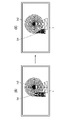
- the user touches a button displayed in the context setting menu Me to set the context of the icon of the subject.
- FIG. 13 shows an example in which the icon Ic1 of the first subject is the operation target. In this case, the icon Ic1 of the first subject is touched for a certain period of time or longer.
- FIG. 14 shows an example in which the icon Ic1 of the first subject is selected to move to the backmost. In this case, as shown in the figure, the icon Ic1 of the first subject is arranged below the icon Ic2 of the second subject.
- Fig. 15 shows an example of a composition set by a series of operations. Information on the set composition is added to the imaging position estimation unit 10E.
- the imaging position estimation unit 10E performs a process of estimating the position (imaging position) where the first subject and the second subject can be imaged with the set composition based on the subject information and the camera information.
- the imaging position here includes a position where an image can be captured with substantially the same composition as the set composition. That is, it estimates a position where an image can be captured with approximately the same composition.
- the composition is set on the display using the subject icons Ic1 and Ic2. Therefore, the imaging position is estimated based on the display state of the icons Ic1 and Ic2 on the display 15. FIG. More specifically, it is estimated based on the display state of the icons Ic1 and Ic2 within the frame F displayed on the display 15 .
- the subject information includes position information and size information of the subject to be imaged.
- the camera information also includes information on the size of the image sensor, information on the focal length of the lens that can be set, and the like.
- the imaging position estimation unit 10E estimates the imaging position using these pieces of information.
- FIG. 16 is a conceptual diagram of imaging position estimation processing.
- point P1 is the position of the first subject selected as the imaging target
- point P2 is the position of the second subject selected as the imaging target.
- the distance to the subject can be obtained from the camera information (size of the image sensor, focal length of the lens, etc.) when the image was captured.
- the size and position of the subject to be imaged are known, and the size of the image sensor and the settable focal length of the lens are also known. Therefore, if the size of the subject in the set composition is known, the distance for imaging the subject at that size can be obtained.
- the size of the subject in the set composition is the size of the subject on the image sensor.
- a dashed-dotted circle C11 centered at a point P1 indicates a position where the first subject can be imaged in the set size when the focal length of the lens is set to the first focal length f1 [mm]. showing.
- a solid-line circle C12 centered at the point P1 indicates a position where the first subject can be imaged in the set size when the focal length of the lens is set to the second focal length f2 [mm]. (f2>f1).
- a dashed circle C13 centered at the point P1 indicates a position where the first subject can be imaged in the set size when the focal length of the lens is set to the third focal length f3 [mm]. (f3>f2).
- a circle C21 with a dashed line centered at the point P2 indicates that the second subject can be imaged in the set size when the focal length of the lens is set to the first focal length f1 [mm]. showing the position.
- a solid-line circle C22 centered at the point P2 indicates a position where the second subject can be imaged in the set size when the focal length of the lens is set to the second focal length f2 [mm].
- a dashed circle C23 centered at the point P2 indicates a position where the second subject can be imaged in the set size when the focal length of the lens is set to the third focal length f3 [mm]. .
- the intersection point to be selected is the intersection point where the left and right positional relationship is the same as the set composition. That is, the positions are such that the first subject and the second subject can be imaged with the same left-right positional relationship as the set composition.
- two intersections X1 and X2 exist in the solid-line circles C21 and C22.
- the first subject is placed on the left side of the image, and the second subject is placed on the right side.
- intersection point X1 becomes an intersection point that can be imaged with a correct left-right positional relationship.
- the first The distance between the subject and the second subject is different. Therefore, by further determining the focal length at which the first subject and the second subject can be imaged at the set intervals, it is possible to determine the positions at which the first subject and the second subject can be imaged with the set composition.
- the imaging position estimation unit 10E changes the focal length step by step and searches for a position where the first subject and the second subject can be imaged with the set composition.
- FIG. 17 is a flow chart showing the procedure for estimating the imaging position.
- the sizes and positional relationships of the first subject and the second subject in the set composition are calculated (step S1). Specifically, the size and positional relationship of the first subject and the second subject on the image sensor are calculated.
- step S2 the calculation parameters for calculating the imaging position are set (step S2).
- a value at the wide end is set as an initial value.
- the imaging position candidates are calculated as positions at which the first subject and the second subject can be imaged in the set composition size. This position is calculated as two points of intersection of the circles. Among the two points of intersection, the point of intersection at which the first subject and the second subject can be imaged in the same horizontal positional relationship as the set composition is selected as a candidate for the imaging position.
- step S4 it is determined whether or not an image with the same composition can be captured when the first subject and the second subject are captured at the selected imaging positions. That is, it is determined whether or not the first subject and the second subject can be imaged with the same left-right positional relationship (interval) as the set composition.
- the selected position is estimated as the imaging position (step S5), and the process ends.
- step S6 it is determined whether or not the focal length can be changed. If the focal length can be changed, the focal length is changed (step S7). The focal length is changed to the tele side by a preset amount of change. After that, based on the changed focal length, candidates for the imaging position are calculated again (step S3).
- the focal length cannot be changed, it is determined that the imaging position cannot be estimated (step S9), and the process ends.
- the focal length cannot be changed when the telephoto end is reached.
- the imaging position estimation unit 10E searches for the imaging position by switching the focal length step by step. Note that when the focal length cannot be changed, it is determined that the imaging position cannot be estimated, so the processing performed by the imaging position estimation unit 10E includes processing for determining whether or not imaging can be performed with the set composition.
- the imaging position estimation unit 10E performs estimation processing of the imaging position in response to an instruction to start processing from the user.
- the user touches the Check & Search button Bt1 (see FIG. 9) displayed in the information display area 15B to instruct the start of processing.
- the processing result of the imaging position estimation unit 10E is added to the result output unit 10F.
- Information on the processing result includes information on the focal length in addition to information on the estimated imaging position. Note that when it is determined that the imaging position cannot be estimated, information indicating that imaging is impossible is added to the result output unit 10F as the processing result.
- the result output unit 10F performs processing for outputting the processing result by the imaging position estimation unit 10E. This processing is performed by displaying the processing result on the display 15 in a predetermined format.
- FIG. 18 and 19 are diagrams showing an example of display of the result of the imaging position estimation processing.
- FIG. 18 shows an example of display when the imaging position can be estimated.
- FIG. 19 shows an example of display when the imaging position cannot be estimated.
- the information on the estimated imaging position is displayed on the display 15 .
- a mark Mx indicating the imaging position is displayed on the map displayed in the map display area 15A.
- Information on the latitude and longitude of the estimated imaging position is also displayed in the information display area 15B.
- information on the focal length at the time of imaging is displayed in the information display area 15B.
- a predetermined error message is displayed in the information display area 15B as shown in FIG.
- the characters "Not Found” are displayed in the information display area 15B as an error message.
- the user will have to reset the composition.
- the composition setting area 15C to reset the composition
- the error message disappears.
- the Check & Search button Bt1 is again displayed in the information display area 15B as shown in FIG. As a result, the start of the imaging position estimation process can be instructed again for the reconfigured composition.
- the information providing server 100 provides various types of information to user terminals.
- the information providing server 100 is composed of a general server computer.
- FIG. 20 is a block diagram showing an example of the hardware configuration of the information providing server.
- the information providing server 100 is used as a CPU 101 that controls the overall operation, a ROM 102 that stores programs used to drive the CPU 101 such as an IPL (Initial Program Loader), and a work area for the CPU 101.
- RAM 103, HDD (Hard Disk Drive) 104 for storing various programs and various data for the information providing server 100, display 105, communication unit 106 for data communication using network 2, keyboard 107, mouse 108, optics A drive 110 and the like are provided.
- FIG. 21 is a block diagram of the main functions provided by the information providing server.
- the information providing server 100 has functions such as a request receiving section 100A, a request processing section 100B, and a request processing result output section 100C.
- the function of each part is realized by the CPU 11 executing a predetermined program.
- the request receiving unit 100A performs processing for receiving requests for information provision from the user terminal 10. That is, it accepts requests for providing map data, providing subject information, and the like.
- the request processing unit 100B processes requests received by the request receiving unit 100A. For example, in response to a request for providing map data, a process of acquiring the corresponding map data is performed. Further, in response to a request for provision of subject information, a process of acquiring corresponding subject information is performed.
- Map data, subject information, etc. are stored in an information database (Data Base, DB) 100D. Therefore, the request processing unit 100B acquires map data, subject information, etc. from the information database 100D.
- Information database 100D is stored in HDD 104, for example.
- the request processing result output unit 100C acquires from the request processing unit 100B the processing result for the request received by the request receiving unit 100A and outputs (transmits) it to the user terminal 10.
- FIG. 22 is a flow chart showing the processing operation of the user terminal. This figure shows the flow of a series of processes from selection of an object to output of the estimation result of the imaging position.
- step S11 a process of acquiring camera information is performed (step S11).
- camera information is stored in ROM 12 and/or EEPROM 14 in this embodiment. Therefore, camera information is obtained from the ROM 13 and/or the EEPROM 14 .
- a process of accepting selection of a subject to be imaged is performed (step S12).
- subject selection is performed using a map.
- the user selects a subject to be imaged on the map displayed on the display 15 . More specifically, the subject to be imaged is selected from the subject candidates Ob displayed on the map. The selection is performed by touching the subject candidate Ob to be imaged for a predetermined time or longer.
- the icon of the selected subject is displayed in the information display area 15B within the screen of the display 15, as shown in FIGS. In this embodiment, two subjects are selected.
- step S13 a process of acquiring subject information of the selected subject is performed.
- Subject information is acquired from the information providing server 100 .
- step S14 a process of receiving composition input is performed (step S14).
- Input of composition is performed using an icon of a subject.
- the user displays the icons used for composition setting in the composition setting area 15C by dragging the icons Ic1 and Ic2 displayed in the information display area 15B to the composition setting area 15C.
- the user sets the composition by moving and/or scaling the icons Ic1 and Ic2 displayed in the composition setting area 15C.
- the imaging position estimation process is performed according to the user's instruction to start the process (step S15).
- the instruction to start processing is performed by touching the Check & Search button Bt1 (see FIG. 9) displayed in the information display area 15B.
- the process of outputting the result is performed (step S16).
- Results are displayed on the display 15 .
- the display contents change depending on whether the imaging position can be estimated or not.
- information on the estimated imaging position is displayed on the display 15 .
- a mark Mx indicating the imaging position is displayed on the map displayed in the map display area 15A.
- information on the latitude and longitude of the estimated imaging position and information on the focal length at the time of imaging are displayed in the information display area 15B.
- the user can grasp the position where the composition set by the user can be imaged and the imaging conditions (focal length).
- a predetermined error message is displayed in the information display area 15B as shown in FIG. The user resets the composition according to this display.
- the imaging position estimation system of the present embodiment it is possible to obtain the position where imaging is possible (imaging position) simply by selecting a subject to be imaged and inputting the composition. This makes it possible to easily capture an image with a desired composition.
- [Modification] Designation of subject
- a map is used to designate (select) an object to be imaged, but the method of designating an object to be imaged is not limited to this.
- subject information is stored in the information database 100D of the information providing server 100 in association with the name of the subject.
- the icon used when setting the composition may be any shape as long as the object can be roughly recognized.
- any form may be used as long as the composition can be roughly set.
- silhouetted representations can also be used.
- composition setting In the above embodiment, the composition is set using a partial area (composition setting area) of the screen of the display. A configuration in which settings are performed may also be used. In this case, the display may be switched to the full screen according to an instruction from the user.
- FIG. 23 is a diagram showing an example of display of the result of estimation processing including the imaging direction. As shown in the figure, when estimating including the imaging position, the estimation result of the imaging direction is displayed on the display 15 together with the imaging position. In the example shown in the figure, the imaging direction is indicated by an arrow Dx extending from the mark Mx indicating the imaging position.
- the imaging position can also be configured to be estimated including the altitude.
- a spherical surface is set instead of the circle, and the position where each subject can be imaged is estimated. That is, when the lens is set to a predetermined focal length fx [mm], the position where each subject can be imaged with the set composition size is represented by a spherical surface, and the intersection of the spherical surfaces is obtained to estimate the imaging position.
- the composition including the orientation of the subject can be set in the set orientation.
- the frontal orientation can be set to estimate the position where the image can be captured.
- the orientation of the subject is set using, for example, a three-dimensional icon or the like so that the orientation can be adjusted.
- the estimated imaging position may be determined whether or not the estimated imaging position is an accessible place.
- the information of the impenetrable place is held in the information database 100D, and it is determined whether or not the estimated imaging position corresponds to the impenetrable place.
- a predetermined warning is given.
- a warning message is displayed on display 15 .
- Inaccessible areas include private land, seas, rivers and lakes. It also includes dangerous areas and areas that are difficult to access. For difficult-to-enter areas such as mountains, for example, information on the travel history of people can be collected, and areas with no travel history can be treated as difficult-to-enter areas.
- the estimated imaging position including the altitude
- a predetermined warning is issued. For example, a warning message is displayed on display 15 .
- Provision of backlit information A function that calculates the time period of backlight and presents the calculated time period information to the user when the first subject and the second subject are imaged from the location estimated to be the imaging position. may be further provided.
- the information on the time period of backlight is displayed in the information display area 15B together with the information on the imaging position, for example.
- the time zone in which the amount of light is insufficient for example, the time zone in which the brightness is equal to or less than the threshold value is calculated.
- the information on the backlight time period and the information on the time period when the amount of light is insufficient may be configured to present both information, or may be configured to present only one of the information.
- the case of capturing images using the camera 18 provided in the user terminal 10 has been described as an example, but it is also possible to capture images using a camera separate from the user terminal. In this case, it is necessary to separately acquire the camera information of the camera to be used.
- a method for acquiring camera information is not particularly limited, and for example, a configuration in which camera information is manually input to a user terminal is also possible. It is also possible to communicate with the camera and automatically acquire the information. Furthermore, it is also possible to obtain the camera information by obtaining the identification information of the camera to be used. In this case, for example, the camera information of each camera is stored in the information database 100 ⁇ /b>D of the information providing server 100 and the camera information of the corresponding camera is obtained from the information providing server 100 .
- the lens has a zoom function, but the lens of the camera may be a so-called single focus lens.
- the focal length is assumed to be constant, and the imaging position is estimated.
- the camera can be configured to be mounted on an unmanned vehicle, an unmanned aircraft (so-called drone), an unmanned ship, or the like for imaging.
- an unmanned vehicle an unmanned aircraft (so-called drone), an unmanned ship, or the like for imaging.
- the range of selectable imaging positions can be expanded.
- the altitude restriction can be lifted.
- the user terminal has the function of the information processing apparatus, but for example, the camera may have the function of the information processing apparatus.
- various information is provided from the information providing server 100, but the user terminal may have the functions of the information providing server 100. In this case, the information providing server becomes unnecessary.
- an immovable subject that is, a subject whose geographical position is fixed (fixed object) is taken as an imaging target
- the subject to be imaged is not limited to this. Any object whose geographical position can be identified at least at the time of imaging can be included in the subject to be imaged. For example, objects that move with regularity, such as celestial bodies, can be included in subjects to be imaged.
- selection of a subject to be imaged is performed by selecting an object on a map or inputting the name of the object.
- FIG. 24 is a diagram showing an example of a screen for subject selection operation.
- a map for selecting a subject is displayed in the map display area 15A. This point is the same as the first embodiment.
- search boxes B1 and B2 displayed in the information display area 15B are used.
- a first search box B1 is displayed in the first icon display area 15b1 set in the information display area 15B.
- a second search box B2 is displayed in the second icon display area 15b2 set in the information display area 15B.
- the name is entered in the first search box B1.
- a character input function provided in the user terminal 10 is used for inputting characters. After entering the name, touch the search button to search for the object. If the subject can be selected, its icon is displayed in the icon display area as a result.
- FIG. 25 is a diagram showing an example of the subject selection result. This figure shows an example of selecting a first subject using a map and selecting a second subject using a name. Also, the figure shows a case where an object whose geographical position is fixed (fixed object) is selected as the first subject, and a celestial body, specifically the moon, is selected as the second subject.
- the composition setting operation is the same as in the first embodiment. It should be noted that when a celestial body is selected as an imaging target, its size cannot be adjusted. Therefore, only the position is adjusted when a subject is selected to be imaged.
- FIG. 26 is a diagram showing an example of the set composition.
- the user sets the desired composition by adjusting the positions and sizes of the icons IC1 and Ic2 in the composition setting area 15C. After that, the user touches the Check & Search button Bt1 displayed in the information display area 15B to instruct the start of the imaging position estimation processing.
- FIG. 27 is a diagram showing an example of a set composition. Also, FIG. 28 is a conceptual diagram of a method for estimating the imaging position.
- point P1 is the geographical position of the first subject.
- a circle C centered at the point P1 and having a radius r indicates a position where the first subject can be imaged with the set composition size when the lens is set to a predetermined focal length fx [mm].
- the height of the first subject is h1
- the height of the second subject is h2.
- w be the distance between the first subject and the second subject.
- the actual height of the first subject is assumed to be H1.
- search for the date and time when the second subject has an elevation angle ⁇ is obtained.
- the observed position (elevation angle and azimuth) can be specified.
- Information on the position of celestial bodies may be obtained from the information providing server 100 or obtained by calculation.
- the orientation indicated by arrow D2 is an example of the obtained orientation. That is, it indicates the direction in which the second subject should be.
- the imaging position PX is specified as a point on a circle C when the first subject is positioned in a direction that is shifted by an angle ⁇ from the direction in which the second subject should be (arrow D2).
- the imaging position PX is the point of intersection with a circle C obtained by drawing a half-line from the first object in a direction that is shifted by an angle ⁇ from the azimuth (arrow D2) where the second object should be.
- the imaging position is estimated through the above series of steps. As described above, when a celestial body is taken as an imaging target, the imaging date and time are estimated in addition to the imaging position.
- FIG. 29 is a diagram showing an example of display of the result of estimation processing.
- a mark Mx indicating the imaging position is displayed on the map displayed in the map display area 15A.
- information such as the estimated latitude and longitude of the imaging position, the focal length at the time of imaging, and the date and time of imaging are displayed in the information display area 15B.
- the shooting date and time are estimated in addition to the shooting position.
- it is also possible to receive the setting of the shooting date and time from the user and determine whether or not the shooting is possible. That is, it may be configured to determine whether or not an image with a set composition can be captured at a set date and time. Whether or not imaging is possible is determined, for example, by determining whether or not the date and time at which the second subject has an elevation angle ⁇ at the point where the first subject exists matches the specified date and time. If the specified date and time do not match, it is determined that imaging is impossible.
- the date and time may be specified within a range.
- FIG. 30 is a block diagram of the main functions realized by the user terminal.
- the user terminal 10 further has the function of an imaging availability determination unit 10G.
- Other functions are substantially the same as those of the first embodiment. Therefore, here, the function of the imaging availability determination unit 10G will be described.
- the function of the imaging availability determination unit 10G is realized by the CPU 11 executing a predetermined program.
- the imaging possibility determination unit 10G acquires the information of the imaging position and the focal length estimated by the imaging position estimation unit 10E, and combines the acquired information of the imaging position and the focal length with the information of the positions of the first subject and the second subject. Based on this, the presence or absence of an object (obstacle) that hinders imaging is determined. That is, it is determined whether or not an obstacle exists within the angle of view when the first subject and the second subject are imaged from the estimated imaging position. Specifically, obstacles between the imaging position and the first and second subjects are detected. Information on obstacles is stored in the information database 100 ⁇ /b>D of the information providing server 100 . An obstacle, for example, an object exceeding a specified size is registered together with its position and size information. The imaging availability determination unit 10G detects obstacles based on the information stored in the information database 100D. If an obstacle is detected, it is determined that imaging is impossible.
- a message is displayed on the display 15 indicating that imaging is impossible due to the presence of an obstacle. If it is determined that the image can be captured, information on the image capturing position and focal length is displayed on the display 15 as usual (see FIG. 18).
- the imaging position is estimated in consideration of obstacles. This makes it possible to present a position where an image with a desired composition can be captured more reliably.
- FIG. 31 is a block diagram of the main functions realized by the user terminal.
- the user terminal 10 of the present embodiment further has the function of a composition correction section 10H.
- Other functions are substantially the same as those of the first embodiment. Therefore, the function of the composition correction unit 10H will be described here.
- the function of the composition corrector 10H is realized by the CPU 11 executing a predetermined program.
- the composition correction unit 10H performs processing for correcting the composition set by the user when the imaging position estimation unit 10E determines that the image cannot be captured. As described above, when the imaging position cannot be estimated, the imaging position estimation unit 10E determines that imaging is impossible with the set composition. When the imaging position cannot be estimated, the composition correction unit 10H corrects the composition set by the user according to a predetermined procedure.
- FIG. 32 is a diagram showing an example of size correction.
- (A) shows the composition before correction
- (B) and (C) show the composition during the correction process
- (D) shows the composition after correction.
- size correction is performed for both the first subject and the second subject, and is performed step by step at a constant ratio.
- the size is corrected to a predetermined ratio and the imaging position cannot be estimated, it is determined that imaging is impossible.
- the composition may be further modified by changing the positional relationship between the first subject and the second subject. .
- the front and rear positions of the first subject and the second subject are interchanged.
- the corrected composition is displayed in the composition setting area 15C.
- FIG. 33 is a diagram showing an example of correction of the front-rear positional relationship.
- (A) of the figure shows the composition before correction.
- (B) of the figure shows the composition after correction.
- the composition correction unit 10H changes the arrangement of the first subject and the second subject to correct the composition.
- the imaging position estimation unit 10E performs processing for estimating the imaging position again for the corrected composition. If the imaging position cannot be estimated with the corrected composition, it is determined that imaging is impossible.
- the corrected composition is displayed in the composition setting area 15C.
- FIG. 34 is a diagram showing an example of correction of the distance between subjects. This figure shows an example of distance correction when the distance between subjects is too short.
- (A) shows the composition before correction
- (B) and (C) show the composition in the process of correction
- (D) shows the composition after correction.
- the distance between the subjects is gradually increased to correct the composition.
- the distance is increased step by step at a constant rate. Correction ends when the imaging position is estimated.
- the imaging position cannot be estimated even after the correction is made up to a predetermined ratio, it is determined that imaging is impossible.
- the imaging position cannot be estimated because the distance between the subjects is too far, correct the distance between the subjects so that they are closer.
- To correct the distance for example, first correct it in the direction of making the distance closer. If the imaging position cannot be estimated by correcting the distance in the direction of shortening, the correction is made in the direction of increasing the distance. Or vice versa.
- the corrected composition is displayed in the composition setting area 15C.
- each of the above corrections can be implemented in combination as appropriate.
- each correction is performed in a predetermined order, and the process ends when the imaging position can be estimated.
- the composition may be corrected in the same way. That is, the composition is corrected so that the first subject and the second subject can be captured while avoiding obstacles. In this case, for example, the composition is corrected by correcting the position of the subject blocked by the obstacle.
- FIG. 35 is a diagram showing an example of correction when an obstacle exists.
- the figure shows an example of correction when an obstacle OX exists in front of the first subject.
- 1A shows the composition before correction
- FIG. 1B shows the composition after correction.
- the position of the first subject is moved to correct the composition. That is, the first subject is moved to a position where it is not hidden by the obstacle.
- the imaging position estimation system of the first embodiment it is possible to estimate a position where a desired composition can be imaged.
- the estimated position is a place where people cannot enter.
- the imaging position if it is possible to grasp in advance how the composition will change, the convenience will be improved.
- a function of correcting the imaging direction in addition to the estimated imaging position and a function of presenting a composition that can be captured when the imaging position and/or the imaging direction are corrected are provided.
- FIG. 36 is a block diagram of the main functions realized by the user terminal.
- the user terminal 10 of the present embodiment further has functions of a correction receiving unit 10I and a composition estimating unit 10J.
- Other functions are substantially the same as those of the first embodiment. Therefore, the functions of the correction receiving unit 10I and the composition estimating unit 10J will be mainly described here.
- the functions of the correction accepting unit 10I and the composition estimating unit 10J are realized by the CPU 11 executing a predetermined program.
- the correction reception unit 10I performs processing for receiving corrections of the imaging position and imaging direction. Correction of the imaging position is performed by moving the mark Mx displayed on the display 15 and indicating the imaging position. Further, the imaging direction is corrected by changing the direction of the arrow Dx displayed on the display 15 and indicating the imaging direction.
- FIG. 37 is a diagram showing an example of a screen for accepting correction of the imaging position and imaging direction.
- a predetermined button (Move button) Bt2 is displayed superimposed on the map in the map display area 15A. By touching the Move button Bt2, it becomes possible to correct the imaging position and imaging direction.
- Move button Bt2 By touching the Move button Bt2, it becomes possible to correct the imaging position and imaging direction.
- To correct the imaging direction move (rotate) the arrow Dx while touching it. It is assumed that the arrow Dx rotates around the mark Mx.
- the composition estimation unit 10J performs processing for estimating the composition to be imaged from the corrected imaging position and imaging direction.
- the result output unit 10F displays the composition estimated by the composition estimation unit 10J in the composition setting area 15C.
- the composition of the image captured after correction can be presented. As a result, it is possible to easily capture an image having a composition captured by the user.
- a range sensor is used to three-dimensionally scan an imaging target and measure its position and size.
- FIG. 38 is a block diagram of the main functions realized by the user terminal.
- the user terminal 10 of the present embodiment further has the functions of a measurement control section 10K and an icon acquisition section 10L.
- Other functions are substantially the same as those of the first embodiment. Therefore, the functions of the measurement control unit 10K and the icon acquisition unit 10L will be mainly described here. Functions of the measurement control unit 10K and the icon acquisition unit 10L are realized by the CPU 11 executing a predetermined program.
- the measurement control unit 10K controls the sensor unit 23 to perform processing for measuring the position and size of the subject to be imaged.
- a range sensor is used to three-dimensionally scan a subject to be imaged, and measure its position and size.
- FIG. 39 is a conceptual diagram of space measurement.
- the position and size of the subject to be imaged are measured with reference to a predetermined position PO in the real space.
- the icon acquisition unit 10L performs processing for acquiring icon information of a subject to be imaged.
- the icon is obtained by capturing an image of a subject to be imaged. Specifically, an image obtained by extracting a subject portion from an image of a subject to be imaged is used as an icon.
- the composition setting unit 10D uses the icons acquired by the icon acquisition unit 10L to accept input of composition.
- the imaging position estimating unit 10E captures an image with the composition set by the composition setting unit 10D based on information on the positions and sizes of the subjects (the first subject and the second subject) obtained by measurement by the measurement control unit 10K. Estimate possible positions.
- an icon is generated from an image of the subject that is actually captured, and the icon is obtained.
- the method of obtaining the icon of the subject is not limited to this.
- a configuration may be adopted in which icons of a plurality of objects (object candidates) are prepared in advance so that the user can select one.
- an icon can be substituted with, for example, a rectangular frame. In this case, it is preferable to let the user input the aspect ratio and use it as an icon of the target subject.
- a function of guiding to the estimated imaging position may be further provided. That is, a navigation function may be further provided.
- the user terminal 10 further has a function of acquiring current location information, a function of generating guidance information leading to the imaging position based on the acquired current location information, a function of guiding based on the generated guidance information, and the like. is provided.
- the guiding function is performed, for example, by displaying generated guidance information on the display 15 .
- a function of guiding the imaging direction may be further provided. That is, it may be provided with a function of indicating the direction of imaging to the user at the actual imaging position.
- the user terminal has a function to acquire information on the direction of the camera (information on the direction of the optical axis), a function to determine the direction in which the camera is pointed based on the acquired information on the direction of the camera, and a function to notify the determined direction. It has a function to Notification of the obtained direction is performed, for example, by displaying direction information on the display. At this time, it is more preferable to display the orientation information superimposed on the live view image.
- an image with a composition set by the user may be displayed over the live view image.
- the composition image is displayed, for example, in a translucent manner.
- an image pickup can be automatically performed based on the estimated image pickup position and image pickup direction. For example, when capturing an image using a camera mounted on an unmanned vehicle, an unmanned aircraft, an unmanned ship, etc., information on the estimated image capturing position and image capturing direction should be given to these devices, and the image captured automatically. can be done. Unmanned vehicles, unmanned aircraft, unmanned ships, etc. equipped with cameras, and the technology itself for automatically capturing images using these are known, so detailed description thereof will be omitted.
- the information providing server is configured to only provide information necessary for estimating the imaging position. good. That is, the configuration is such that the user terminal is used as an interface, and the processing for estimating the imaging position and the like are performed by the information providing server.
- the information providing server functions as an information processing device. Also, in this case, the user terminal constitutes another display device.
- the user terminal may have the function of the information providing server. That is, the functions of the user terminal and the functions of the information providing server may be realized by one device.
- Hardware Configuration Functions of the user terminal are realized by various processors.
- Various processors include CPUs and/or GPUs (Graphic Processing Units), FPGAs (Field Programmable Gate Arrays), etc., which are general-purpose processors that execute programs and function as various processing units.
- Programmable Logic Device PLD
- ASIC Application Specific Integrated Circuit
- a dedicated electric circuit which is a processor having a circuit configuration specially designed to execute specific processing, etc. included.
- a program is synonymous with software.
- a single processing unit may be composed of one of these various processors, or may be composed of two or more processors of the same type or different types.
- one processing unit may be composed of a plurality of FPGAs or a combination of a CPU and an FPGA.
- a plurality of processing units may be configured by one processor.
- a single processor is configured with a combination of one or more CPUs and software, as typified by computers used for clients and servers. , in which the processor functions as a plurality of processing units.
- SoC System on Chip
- the various processing units are configured using one or more of the above various processors as a hardware structure.
- Imaging position estimation system 2 network 10 user terminal 10A camera information acquisition unit 10B subject selection unit 10C subject information acquisition unit 10D composition setting unit 10E imaging position estimation unit 10F result output unit 10G imaging availability determination unit 10H composition correction unit 10I correction reception unit 10J composition estimation unit 10K measurement control unit 10L icon acquisition unit 11
Landscapes
- Engineering & Computer Science (AREA)
- Physics & Mathematics (AREA)
- General Physics & Mathematics (AREA)
- Theoretical Computer Science (AREA)
- Computer Vision & Pattern Recognition (AREA)
- Human Computer Interaction (AREA)
- General Engineering & Computer Science (AREA)
- Geometry (AREA)
- Studio Devices (AREA)
Priority Applications (3)
| Application Number | Priority Date | Filing Date | Title |
|---|---|---|---|
| CN202280057940.7A CN117897962A (zh) | 2021-08-27 | 2022-06-29 | 信息处理装置、信息处理方法及信息处理程序 |
| JP2023543732A JP7814396B2 (ja) | 2021-08-27 | 2022-06-29 | 情報処理装置、情報処理方法及び情報処理プログラム並びに記録媒体 |
| US18/584,939 US20240233168A1 (en) | 2021-08-27 | 2024-02-22 | Information processing apparatus, information processing method, and information processing program |
Applications Claiming Priority (2)
| Application Number | Priority Date | Filing Date | Title |
|---|---|---|---|
| JP2021-139098 | 2021-08-27 | ||
| JP2021139098 | 2021-08-27 |
Related Child Applications (1)
| Application Number | Title | Priority Date | Filing Date |
|---|---|---|---|
| US18/584,939 Continuation US20240233168A1 (en) | 2021-08-27 | 2024-02-22 | Information processing apparatus, information processing method, and information processing program |
Publications (1)
| Publication Number | Publication Date |
|---|---|
| WO2023026686A1 true WO2023026686A1 (ja) | 2023-03-02 |
Family
ID=85322712
Family Applications (1)
| Application Number | Title | Priority Date | Filing Date |
|---|---|---|---|
| PCT/JP2022/025910 Ceased WO2023026686A1 (ja) | 2021-08-27 | 2022-06-29 | 情報処理装置、情報処理方法及び情報処理プログラム |
Country Status (4)
| Country | Link |
|---|---|
| US (1) | US20240233168A1 (https=) |
| JP (1) | JP7814396B2 (https=) |
| CN (1) | CN117897962A (https=) |
| WO (1) | WO2023026686A1 (https=) |
Citations (1)
| Publication number | Priority date | Publication date | Assignee | Title |
|---|---|---|---|---|
| JP2006238082A (ja) * | 2005-02-25 | 2006-09-07 | Casio Comput Co Ltd | デジタルカメラ及びカメラの撮影位置モニタ方法 |
Family Cites Families (14)
| Publication number | Priority date | Publication date | Assignee | Title |
|---|---|---|---|---|
| JP2006203863A (ja) * | 2004-12-24 | 2006-08-03 | Fuji Photo Film Co Ltd | 撮像システム及び撮像方法 |
| JP2009239397A (ja) * | 2008-03-26 | 2009-10-15 | Seiko Epson Corp | 撮影装置、撮影システム、撮影装置の制御方法および制御プログラム |
| CN101784980B (zh) * | 2008-06-02 | 2013-09-18 | 松下电器产业株式会社 | 遥控操作装置及遥控操作方法 |
| JP5425305B2 (ja) * | 2010-05-31 | 2014-02-26 | 富士フイルム株式会社 | 立体画像制御装置ならびにその動作制御方法およびその動作制御プログラム |
| EP2858341B1 (en) * | 2012-05-30 | 2019-07-17 | Sony Corporation | Information processing device, system, and storage medium |
| JP6076168B2 (ja) * | 2013-03-27 | 2017-02-08 | オリンパス株式会社 | 撮像装置、構図アシスト装置、構図アシスト方法、及び構図アシストプログラム |
| JPWO2014178228A1 (ja) * | 2013-04-30 | 2017-02-23 | ソニー株式会社 | クライアント端末、表示制御方法、プログラム、およびシステム |
| US9836655B2 (en) * | 2014-06-24 | 2017-12-05 | Nec Corporation | Information processing apparatus, information processing method, and computer-readable medium |
| JP2017011469A (ja) * | 2015-06-22 | 2017-01-12 | カシオ計算機株式会社 | 撮影装置、撮影方法、およびプログラム |
| US10470825B2 (en) * | 2017-08-16 | 2019-11-12 | Synaptive Medical (Barbados) Inc. | Method, system and apparatus for surface rendering using medical imaging data |
| US11315313B2 (en) * | 2018-02-23 | 2022-04-26 | Sony Group Corporation | Methods, devices and computer program products for generating 3D models |
| US10785406B2 (en) * | 2019-02-01 | 2020-09-22 | Qualcomm Incorporated | Photography assistance for mobile devices |
| US11348682B2 (en) * | 2020-04-05 | 2022-05-31 | Theator, Inc. | Automated assessment of surgical competency from video analyses |
| US11741618B2 (en) * | 2021-03-22 | 2023-08-29 | Everypoint, Inc. | Performing object modeling by combining visual data from images with motion data of the image acquisition device |
-
2022
- 2022-06-29 JP JP2023543732A patent/JP7814396B2/ja active Active
- 2022-06-29 WO PCT/JP2022/025910 patent/WO2023026686A1/ja not_active Ceased
- 2022-06-29 CN CN202280057940.7A patent/CN117897962A/zh active Pending
-
2024
- 2024-02-22 US US18/584,939 patent/US20240233168A1/en active Pending
Patent Citations (1)
| Publication number | Priority date | Publication date | Assignee | Title |
|---|---|---|---|---|
| JP2006238082A (ja) * | 2005-02-25 | 2006-09-07 | Casio Comput Co Ltd | デジタルカメラ及びカメラの撮影位置モニタ方法 |
Also Published As
| Publication number | Publication date |
|---|---|
| US20240233168A1 (en) | 2024-07-11 |
| CN117897962A (zh) | 2024-04-16 |
| JPWO2023026686A1 (https=) | 2023-03-02 |
| JP7814396B2 (ja) | 2026-02-16 |
Similar Documents
| Publication | Publication Date | Title |
|---|---|---|
| US10337865B2 (en) | Geodetic surveying system | |
| US9689972B2 (en) | Scanner display | |
| CN1761855B (zh) | 大地测量仪器中的图像处理方法和装置 | |
| US9525964B2 (en) | Methods, apparatuses, and computer-readable storage media for providing interactive navigational assistance using movable guidance markers | |
| EP2348700A1 (en) | Mobile communication terminal and method | |
| EP3772217A1 (en) | Output control apparatus, display terminal, remote control system, control method, and carrier medium | |
| US11869159B2 (en) | High density 3D environment capture with guided mixed reality | |
| KR101259598B1 (ko) | 로드뷰 제공 장치 및 방법 | |
| JP2007017406A (ja) | 地理データ収集装置 | |
| JP4077385B2 (ja) | 画像処理を用いたグローバル座標取得装置 | |
| EP3318841B1 (en) | Camera controller | |
| WO2022077238A1 (zh) | 成像显示方法、遥控终端、装置、系统及存储介质 | |
| US20140330512A1 (en) | Electronic device with object indication function and an object indicating method thereof | |
| JP2020071324A (ja) | 情報処理装置、その制御方法、プログラム、及び記憶媒体 | |
| JP2018113652A (ja) | 画像取得装置、画像取得システム、画像取得方法、及び画像取得プログラム | |
| CN116229753A (zh) | 寻车的导航方法及其装置 | |
| JP7814396B2 (ja) | 情報処理装置、情報処理方法及び情報処理プログラム並びに記録媒体 | |
| JP2019002747A (ja) | 目的地特定システム | |
| JP2008154027A (ja) | 撮影装置、撮影方法、およびプログラム | |
| JP4167509B2 (ja) | 測量システム | |
| JP2010171664A (ja) | 携帯情報端末、情報表示制御方法、及び、情報表示制御プログラム | |
| JP6673699B2 (ja) | 地形表示システム | |
| JP2014225782A (ja) | 情報処理装置、通信端末およびデータ取得方法 | |
| JP5001400B2 (ja) | 遮蔽物除去表示装置 | |
| JP4319476B2 (ja) | 測量システム |
Legal Events
| Date | Code | Title | Description |
|---|---|---|---|
| WWE | Wipo information: entry into national phase |
Ref document number: 2023543732 Country of ref document: JP |
|
| WWE | Wipo information: entry into national phase |
Ref document number: 202280057940.7 Country of ref document: CN |
|
| NENP | Non-entry into the national phase |
Ref country code: DE |
|
| 122 | Ep: pct application non-entry in european phase |
Ref document number: 22860978 Country of ref document: EP Kind code of ref document: A1 |