WO2023022008A1 - カップリング装置 - Google Patents
カップリング装置 Download PDFInfo
- Publication number
- WO2023022008A1 WO2023022008A1 PCT/JP2022/029945 JP2022029945W WO2023022008A1 WO 2023022008 A1 WO2023022008 A1 WO 2023022008A1 JP 2022029945 W JP2022029945 W JP 2022029945W WO 2023022008 A1 WO2023022008 A1 WO 2023022008A1
- Authority
- WO
- WIPO (PCT)
- Prior art keywords
- valve
- sub
- joint
- coupling device
- filter
- Prior art date
- Legal status (The legal status is an assumption and is not a legal conclusion. Google has not performed a legal analysis and makes no representation as to the accuracy of the status listed.)
- Ceased
Links
Images

Classifications
-
- F—MECHANICAL ENGINEERING; LIGHTING; HEATING; WEAPONS; BLASTING
- F16—ENGINEERING ELEMENTS AND UNITS; GENERAL MEASURES FOR PRODUCING AND MAINTAINING EFFECTIVE FUNCTIONING OF MACHINES OR INSTALLATIONS; THERMAL INSULATION IN GENERAL
- F16L—PIPES; JOINTS OR FITTINGS FOR PIPES; SUPPORTS FOR PIPES, CABLES OR PROTECTIVE TUBING; MEANS FOR THERMAL INSULATION IN GENERAL
- F16L37/00—Couplings of the quick-acting type
- F16L37/28—Couplings of the quick-acting type with fluid cut-off means
- F16L37/30—Couplings of the quick-acting type with fluid cut-off means with fluid cut-off means in each of two pipe-end fittings
- F16L37/32—Couplings of the quick-acting type with fluid cut-off means with fluid cut-off means in each of two pipe-end fittings at least one of two lift valves being opened automatically when the coupling is applied
-
- F—MECHANICAL ENGINEERING; LIGHTING; HEATING; WEAPONS; BLASTING
- F16—ENGINEERING ELEMENTS AND UNITS; GENERAL MEASURES FOR PRODUCING AND MAINTAINING EFFECTIVE FUNCTIONING OF MACHINES OR INSTALLATIONS; THERMAL INSULATION IN GENERAL
- F16L—PIPES; JOINTS OR FITTINGS FOR PIPES; SUPPORTS FOR PIPES, CABLES OR PROTECTIVE TUBING; MEANS FOR THERMAL INSULATION IN GENERAL
- F16L29/00—Joints with fluid cut-off means
- F16L29/04—Joints with fluid cut-off means with a cut-off device in each of the two pipe ends, the cut-off devices being automatically opened when the coupling is applied
-
- B—PERFORMING OPERATIONS; TRANSPORTING
- B01—PHYSICAL OR CHEMICAL PROCESSES OR APPARATUS IN GENERAL
- B01D—SEPARATION
- B01D35/00—Filtering devices having features not specifically covered by groups B01D24/00 - B01D33/00, or for applications not specifically covered by groups B01D24/00 - B01D33/00; Auxiliary devices for filtration; Filter housing constructions
- B01D35/02—Filters adapted for location in special places, e.g. pipe-lines, pumps, stop-cocks
-
- F—MECHANICAL ENGINEERING; LIGHTING; HEATING; WEAPONS; BLASTING
- F16—ENGINEERING ELEMENTS AND UNITS; GENERAL MEASURES FOR PRODUCING AND MAINTAINING EFFECTIVE FUNCTIONING OF MACHINES OR INSTALLATIONS; THERMAL INSULATION IN GENERAL
- F16L—PIPES; JOINTS OR FITTINGS FOR PIPES; SUPPORTS FOR PIPES, CABLES OR PROTECTIVE TUBING; MEANS FOR THERMAL INSULATION IN GENERAL
- F16L37/00—Couplings of the quick-acting type
- F16L37/28—Couplings of the quick-acting type with fluid cut-off means
- F16L37/30—Couplings of the quick-acting type with fluid cut-off means with fluid cut-off means in each of two pipe-end fittings
- F16L37/32—Couplings of the quick-acting type with fluid cut-off means with fluid cut-off means in each of two pipe-end fittings at least one of two lift valves being opened automatically when the coupling is applied
- F16L37/34—Couplings of the quick-acting type with fluid cut-off means with fluid cut-off means in each of two pipe-end fittings at least one of two lift valves being opened automatically when the coupling is applied at least one of the lift valves being of the sleeve type, i.e. a sleeve being telescoped over an inner cylindrical wall
-
- F—MECHANICAL ENGINEERING; LIGHTING; HEATING; WEAPONS; BLASTING
- F16—ENGINEERING ELEMENTS AND UNITS; GENERAL MEASURES FOR PRODUCING AND MAINTAINING EFFECTIVE FUNCTIONING OF MACHINES OR INSTALLATIONS; THERMAL INSULATION IN GENERAL
- F16L—PIPES; JOINTS OR FITTINGS FOR PIPES; SUPPORTS FOR PIPES, CABLES OR PROTECTIVE TUBING; MEANS FOR THERMAL INSULATION IN GENERAL
- F16L37/00—Couplings of the quick-acting type
- F16L37/28—Couplings of the quick-acting type with fluid cut-off means
- F16L37/30—Couplings of the quick-acting type with fluid cut-off means with fluid cut-off means in each of two pipe-end fittings
- F16L37/32—Couplings of the quick-acting type with fluid cut-off means with fluid cut-off means in each of two pipe-end fittings at least one of two lift valves being opened automatically when the coupling is applied
- F16L37/35—Couplings of the quick-acting type with fluid cut-off means with fluid cut-off means in each of two pipe-end fittings at least one of two lift valves being opened automatically when the coupling is applied at least one of the valves having an axial bore communicating with lateral apertures
-
- F—MECHANICAL ENGINEERING; LIGHTING; HEATING; WEAPONS; BLASTING
- F16—ENGINEERING ELEMENTS AND UNITS; GENERAL MEASURES FOR PRODUCING AND MAINTAINING EFFECTIVE FUNCTIONING OF MACHINES OR INSTALLATIONS; THERMAL INSULATION IN GENERAL
- F16L—PIPES; JOINTS OR FITTINGS FOR PIPES; SUPPORTS FOR PIPES, CABLES OR PROTECTIVE TUBING; MEANS FOR THERMAL INSULATION IN GENERAL
- F16L55/00—Devices or appurtenances for use in, or in connection with, pipes or pipe systems
- F16L55/24—Preventing accumulation of dirt or other matter in pipes, e.g. by traps, by strainers
-
- F—MECHANICAL ENGINEERING; LIGHTING; HEATING; WEAPONS; BLASTING
- F16—ENGINEERING ELEMENTS AND UNITS; GENERAL MEASURES FOR PRODUCING AND MAINTAINING EFFECTIVE FUNCTIONING OF MACHINES OR INSTALLATIONS; THERMAL INSULATION IN GENERAL
- F16L—PIPES; JOINTS OR FITTINGS FOR PIPES; SUPPORTS FOR PIPES, CABLES OR PROTECTIVE TUBING; MEANS FOR THERMAL INSULATION IN GENERAL
- F16L58/00—Protection of pipes or pipe fittings against corrosion or incrustation
- F16L58/18—Protection of pipes or pipe fittings against corrosion or incrustation specially adapted for pipe fittings
Definitions
- the present invention relates to a coupling device that separably connects supply/discharge paths formed in a first joint and a second joint.
- Patent Document 1 Japanese Patent Laid-Open No. 60-67042
- Patent Document 2 Japanese Patent Laid-Open No. 2003-117748
- Patent Document 1 has a male plug and a female plug.
- An inlet/outlet valve and a main valve are provided in series in the plug case of the female plug.
- a passage for communicating the valve chamber of the inlet/outlet valve and the valve chamber of the main valve is provided inside the plug case and radially outside the valve chambers.
- a ring-shaped protective filter is mounted in an annular space formed in the middle of the flow path.
- the quick joint of Patent Document 2 has a plug as a first joint and a socket as a second joint.
- a second flow path and a check valve chamber are provided in series in the housing of the plug.
- a second closing member is inserted into the second flow path, and a check member is inserted into the check valve chamber.
- a flow path that communicates the second flow path with the check valve chamber is formed inside the housing and radially outside the second closing member.
- a cylindrical filter is attached to the channel.
- JP-A-60-67042 Japanese Patent Application Laid-Open No. 2003-117748
- a flow passage is formed outside the valve chamber for communicating the valve chamber of the main valve and the valve chamber of the inlet/outlet valve, and a filter is mounted in the middle of the flow passage. . For this reason, the radial dimension of the female plug is increased by the distance of the channel and the filter.
- a flow path for communicating the second flow path and the check valve chamber is formed radially outside the second closing member, and a cylindrical shape is formed in the middle of the flow path. filter is installed. For this reason, the radial dimension of the plug is increased by the distance of the flow path and the filter.
- the diameter of the coupling devices (couplings, quick joints, etc.) of Patent Documents 1 and 2 is generally small, for example, about 20 mm. There is a need to maintain or increase the flow rate of fluid that can flow through the small coupling device while making its overall dimensions more compact than conventional coupling devices.
- An object of the present invention is to provide a compact coupling device.
- the present invention for example, as shown in FIGS. 1 to 3 and 4 to 6, has a coupling device configured as follows.
- the coupling device has a first joint 3 and a second joint 4 detachably connected to the first joint 3 .
- a first supply/discharge path 5 is provided in the first joint 3 .
- a second supply/discharge path 6 detachably connected to the first supply/discharge path 5 is provided in the second joint 4 .
- a sub valve chamber 27 and a main valve chamber 28 are formed in the second joint 4 so as to be continuous from the distal end side to the proximal end side in the axial direction.
- a sub-valve member 33 is movably inserted in the sub-valve chamber 27 in the axial direction and hermetically inserted through a sealing member 34 .
- the sub-valve member 33 is biased by a second valve-closing spring 40 toward the tip side toward the sub-valve seat 32 formed in the sub-valve chamber 27 .
- the sub-valve member 33 has a sub-valve surface 41 that can come into contact with the sub-valve seat 32 .
- a main valve member 43 is hermetically inserted into the main valve chamber 28 so as to be movable in the axial direction. The main valve member 43 can come into contact with the sub-valve member 33 .
- main valve member 43 is biased by a third valve closing spring 48 toward the distal end side toward the main valve seat 42 formed in the main valve chamber 28 .
- a communicating passage 35 as a part of the second supply/discharge passage 6 is formed in the sub-valve member 33 .
- the present invention has the following effects.
- the communication passage as part of the second supply/discharge passage is formed in the sub-valve member. Therefore, the coupling device of the present invention can be made more compact than the above-described conventional coupling device in which the communication passage connecting the sub-valve chamber and the main valve chamber is formed outside the valve chamber.
- the present invention include the following configurations (1) to (3).
- (1) For example, as shown in FIGS. 1 to 3 and 4 to 6, on the outer peripheral surface of the sub-valve member 33, the portion sealed by the sealing member 34 and the sub-valve surface 41, one end of the communicating passage 35 is opened. The other end of the communication passage 35 is between the sub-valve member 33 and the main valve member 43 and communicates with the sub-valve chamber 27 .
- the communication passage is formed in the sub-valve member inserted into the sub-valve chamber. In other words, the communication passage is formed to fit inside the sub-valve chamber.
- the coupling device of the present invention can be made more compact than the above-described conventional coupling device in which the communication passage is formed outside the valve chamber.
- a filter 38 is mounted in the middle of the communicating passage 35 .
- the communication passage and the filter can be accommodated inside the sub-valve member inserted into the sub-valve chamber. Therefore, the coupling device of the present invention can be made more compact than the conventional coupling device in which the communicating passage and the filter are provided outside the valve chamber.
- a support member 36 projecting from the wall surface of the communication passage 35 supports a disk-shaped filter 38 .
- the sub-valve member 33 can come into contact with the main valve member 43 via the support member 36 and the filter 38 .
- the portion of the disk-shaped filter that supports the filter such as the portion that contacts the support member (hereinafter referred to as the supported portion), does not function to remove foreign matter. Therefore, by minimizing the portion that supports the filter, the overall size of the coupling device can be reduced.
- the coupling device of the present invention only the outer peripheral edge portion and the supported portion do not exhibit the foreign matter removing function. For this reason, in contrast to the conventional technology (Patent Document 1) that requires a central opening and inner and outer peripheral edges of the central opening, the present invention employs a conventional inner peripheral pressing mechanism.
- the overall dimensions of the coupling device can be made small, since no additional
- FIG. 1 shows a first embodiment of the present invention, and is a sectional view showing a state in which a first joint and a second joint of a coupling device are separated.
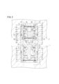
- FIG. 2 is a sectional view similar to FIG. 1, showing a state in which the first joint and the second joint of the coupling device are connected.
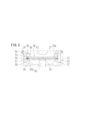
- FIG. 3 is a partially enlarged view of a portion A shown in FIG.
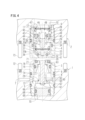
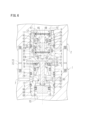
- FIG. 4 shows a second embodiment of the present invention, and is a sectional view showing a state in which the first joint and the second joint of the coupling device are separated.
- FIG. 5 is a cross-sectional view similar to FIG. 4 showing a state in which the first joint and the second joint of the coupling device are in contact with each other.
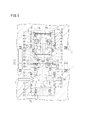
- FIG. 6 is a cross-sectional view similar to FIG. 4 showing a state in which the first joint and the second joint of the coupling device are connected.
- FIG. 1 and 2 includes a first joint 3 and a second joint 4 detachably connected to the first joint 3 from the distal end side.
- a first supply/discharge passage 5 provided in the first joint 3 and a second supply/discharge passage 6 provided in the second joint 4 are separably connected.
- a flow path 7 for compressed air (pressure fluid) formed in the first block 1 is communicated with a mounting hole 8 opened in the upper surface of the first block 1 .
- a first casing 9 of the first joint 3 is tightly screwed into the mounting hole 8 .
- a flow path 10 for compressed air is formed in the second block 2 , and the flow path 10 communicates with a mounting hole 11 opened in the lower surface of the second block 2 .
- the second casing 12 of the second joint 4 is hermetically inserted into the mounting hole 11 .
- a hole opened in the lower surface of the first casing 9 constitutes the supply/discharge port 13 , and the upper portion of the first casing 9 defines the first valve chamber 14 .
- the first valve chamber 14 and the supply/discharge port 13 are separated by a partition wall 15, and six through holes 16 (two through holes 16 are shown in FIGS. 1 and 2) formed in the partition wall 15. is shown).
- a first filter 17 is attached to the inner peripheral wall of the supply/discharge port 13 so as to cover the supply/discharge port 13 . As a result, foreign matter such as dust contained in the compressed air from the supply source is removed by the first filter 17 .
- a tubular first valve member 18 is hermetically inserted into the first valve chamber 14 so as to be vertically movable.
- the upper inner peripheral wall of the tubular hole 19 of the first valve member 18 is formed in a tapered shape so as to widen upward (toward the distal end).
- a first valve surface 20 is annularly formed in the tapered portion.
- a groove is opened in the circumferential direction in the distal end surface of the first valve member 18 outside the first valve surface 20, and an annular sealing member 21 is mounted in the groove.
- a substantially cylindrical valve seat member 22 protrudes upward into the first valve chamber 14 from the partition wall 15 in the first casing 9 .
- the upper portion of the valve seat member 22 is tapered so as to widen upward.
- a first valve seat 23 is formed on the tapered surface of the valve seat member 22 in the circumferential direction. The first valve surface 20 can come into contact with the first valve seat 23 .
- a first valve closing spring 24 is mounted between the cylindrical first valve member 18 and the partition wall 15 . It is biased upwards.
- the first supply/discharge passage 5 is configured by the supply/discharge port 13 of the first casing 9, the through hole 16, the first valve chamber 14, and the cylinder hole 19 of the first valve member 18.
- the above second joint 4 is configured as follows.
- the plug portion 25 of the second joint 4 is integrally formed with the second casing 12 so as to protrude downward from the second casing 12 , and a receiving surface 26 is formed on the lower surface of the plug portion 25 .
- the receiving surface 26 can come into contact with the sealing member 21 attached to the first valve member 18 of the first joint 3 .
- the plug portion 25 can be inserted into the first valve chamber 14 of the first joint 3 .
- a second valve chamber (auxiliary valve chamber) 27 and a third valve chamber (main valve chamber) 28 are formed in order from the bottom in the second casing 12 described above.
- the second valve chamber 27 and the third valve chamber 28 are separated by a partition wall 29 formed inside the second casing 12 .
- a guide hole 30 penetrating through the center of the partition wall 29 allows the second valve chamber 27 and the third valve chamber 28 to communicate with each other.
- a communication groove 31 is vertically formed in the peripheral wall of the guide hole 30 .
- the second valve chamber 27 opens to the lower surface of the plug portion 25 .
- the third valve chamber 28 is opened to the upper surface of the second casing 12 .
- a second valve seat (auxiliary valve seat) 32 is formed in the circumferential direction on the inner peripheral wall near the opening of the second valve chamber 27 so as to narrow downward (closer to the axis).
- a second valve member (sub-valve member) 33 is hermetically inserted into the second valve chamber 27 by a sealing member 34 so as to be vertically movable (in the axial direction of the second casing 12).
- a recess 35a is formed in the upper portion of the second valve member 33, and a support pin (support member) 36 protrudes upward from the bottom wall thereof.
- a stepped portion 37 is provided on the inner peripheral wall of the recessed portion 35a.
- a disk-shaped second filter (filter) 38 is mounted on the stepped portion 37, and the central portion of the second filter 38 is supported by a support pin 36 from below. ing.
- a chamber partitioned by the inner peripheral wall of the recess 35a and the second filter 38 has six through holes 35b (only two through holes 35b are shown in FIGS. 1 to 3) in the cylinder wall of the second valve member 33. ) to the chamber defined by the outer peripheral surface of the second valve member 33 and the inner peripheral surface of the second valve chamber 27 .
- the communication path 35 is configured by the recess 35a and the through hole 35b.
- a through hole 35 b is also opened on the outer peripheral surface of the second valve member 33 .
- the opening is opened between the sealing portion on the outer peripheral surface of the second valve member 33 that contacts the sealing member 34 and the second valve surface 41 described later.
- a second valve closing spring 40 is mounted between the partition wall 29 and the stepped portion 37 of the recessed portion 35a via a second filter 38 so that the second valve closing spring 40 acts against the partition wall 29 as the second valve.
- Member 33 is biased downward toward second valve seat 32 .
- a tapered surface is formed on the lower outer peripheral wall of the second valve member 33, and a housing groove is opened in the tapered surface in the circumferential direction.
- a sealing member is attached to the housing groove, and the outer peripheral surface of the sealing member constitutes a second valve surface (sub-valve surface) 41 .
- the second valve surface 41 can come into contact with the second valve seat 32 .
- the lower portion of the inner peripheral wall of the third valve chamber 28 is formed in a tapered shape so as to narrow downward (closer to the axis). It is formed.
- a third valve member (main valve member) 43 is hermetically inserted into the third valve chamber 28 so as to be vertically movable (in the axial direction of the second casing 12).
- the third valve member 43 has a cylindrical portion 44 and a tapered portion 45 in order from the bottom.
- the cylindrical portion 44 is movably inserted into the guide hole 30 .
- the lower end surface (tip surface) of the columnar portion 44 can abut on the central portion of the second filter 38 with a predetermined gap therebetween.
- the tapered portion 45 is formed so as to widen upward.
- a recess 46 is formed in the upper portion of the third valve member 43 .
- a third valve closing spring 48 is mounted between the bottom wall of the recess 46 and a disk-shaped third filter 47 mounted on the inner peripheral wall of the second casing 12 .
- the third valve closing spring 48 urges the third valve member 43 downward toward the third valve seat 42 with respect to the second casing 12 .
- a housing groove is formed in the outer peripheral wall of the tapered portion 45 of the third valve member 43 in the circumferential direction.
- a sealing member is mounted in the accommodation groove, and a third valve surface 49 is formed on the outer peripheral surface of the sealing member.
- the second valve surface 41 is engaged with the second valve seat 32 and the third valve surface 49 is engaged with the third valve seat 42, and the lower end surface of the columnar portion 44 is the second valve surface.
- the lower end surface of the cylindrical portion 44 may be in contact with the central portion of the second filter 38 in the above state.
- the third valve closing spring 48 is mounted between the third valve member 43 and the thin third filter 47 . Therefore, it is necessary to prevent the third filter 47 from being plastically deformed or damaged by the biasing force of the third valve closing spring 48 . Therefore, the maximum biasing force of the third valve closing spring 48 is set sufficiently smaller than the maximum biasing force of the second valve closing spring 40 . However, it is also necessary for the third valve closing spring 48 to push the third valve member 43 in certain cases. Therefore, it is necessary to set the biasing force of the third valve closing spring 48 so as to exceed the weight of the third valve member 43 and resistance such as sliding resistance.
- the second filter 38 and the third filter 47 are configured in substantially the same way.
- the configuration will be described with reference to FIG. 3 which shows the second filter 38 .
- the filter 38 has a lower supporting member 50, a lower spacer 51, a wire mesh 52, an upper spacer 53, and an upper supporting member 54 which are provided in order from the bottom.
- the lower support member 50 is a disk-shaped plate having a plurality of circular holes (so-called punching metal). Its central portion is formed to protrude upward.
- An annular lower spacer 51 is mounted on the outer edge portion of the lower support member 50 , and a circular wire mesh 52 is mounted on the lower spacer 51 .
- a gap corresponding to the thickness of the lower spacer 51 is formed between the lower support member 50 and the wire mesh 52, and the compressed air flows smoothly through the gap.
- An upper spacer 53 (which is the same member as the lower spacer) is mounted on the outer edge of the wire mesh 52 , and a disk-shaped upper support member 54 is mounted on the upper spacer 53 .
- a gap is also formed between the wire mesh 52 and the upper support member 54, and the compressed air flows smoothly through the gap.
- the upper support member 54 is made of the same material as the lower support member 50 and has the same external dimensions and thickness, it does not have the projecting portion 55 like the lower support member 50 does.
- a wire mesh 52 is sandwiched between the projecting portion 55 of the lower support member 50 and the central portion of the upper support member 54 .
- the second filter 38 is inserted into the recess 35a of the second valve member 33 and received by the stepped portion 37 of the second valve member 33 from below.
- a fixed ring 56 is press-fitted into the recessed portion 35a of the second valve member 33 from above the second filter 38, or a part of the inner peripheral wall of the recessed portion 35a is plastically deformed while the fixed ring 56 is inserted into the recessed portion 35a. It is deformed and fixed.
- the above coupling device is connected and disconnected as follows. First, as shown in FIG. 1, the second block 2 is separated from the first block 1, and the coupling device is in the disengaged state. In the disengaged state of the first joint 3 , the first valve closing spring 24 biases the first valve member 18 against the partition wall 15 of the first casing 9 toward the tip of the valve seat member 22 . Therefore, the first valve surface 20 of the first valve member 18 is engaged with the first valve seat 23 of the valve seat member 22 to close the valve.
- the second valve member 33 is urged downward toward the second valve seat 32 by the second valve closing spring 40 . Therefore, the second valve surface 41 of the second valve member 33 is engaged with the second valve seat 32 to close the valve. Further, the third valve member 43 is urged downward toward the third valve seat 42 by the third valve closing spring 48 . Therefore, the third valve surface 49 of the third valve member 43 is engaged with the third valve seat 42 to close the valve.
- the receiving surface 26 of the plug portion 25 of the second joint 4 contacts the sealing member 21 of the first joint 3. engaged.
- the second valve member 33 of the second joint 4 is engaged with the valve seat member 22 of the first joint 3 .
- the plug portion 25 moves the first valve member 18 downward against the biasing force of the first valve closing spring 24 .
- the first valve surface 20 is separated from the first valve seat 23 and the valve is opened.
- the second valve member 33 is received by the valve seat member 22 when the plug portion 25 is inserted into the first valve chamber 14 , the second valve member 33 is placed against the valve seat member 25 with respect to the plug portion 25 .
- a switching valve (not shown) is provided in the middle of the flow path 7 formed in the first block 1 .
- the switching valve switches between a state in which the coupling device and the compressed air supply source are connected and a state in which the coupling device and the discharge port are connected.
- the compressed air flows in the coupling device as follows. First, compressed air from a supply source flows through the flow path 7 into the supply/discharge port 13 of the first joint 3 . Then, it is supplied to the first valve chamber 14 through the first filter 17 and the through hole 16 . The compressed air in the first valve chamber 14 passes through the valve opening gap formed between the first valve surface 20 and the first valve seat 23 and the opening gap formed between the second valve surface 41 and the second valve seat 32 . It flows into the second valve chamber 27 through the valve gap. Next, the compressed air in the second valve chamber 27 passes through the second filter 38 , the valve opening gap formed between the communication groove 31 , the third valve surface 49 and the third valve seat 42 , and the third filter 47 . supplied to the actuator through
- the switching valve switches the coupling device so that it communicates with the discharge port. Then, the compressed air in the actuator is discharged to the outside from the discharge port in the reverse order of the order described above.
- a concave portion 35 a and a through hole 35 b formed in the upper portion of the second valve member 33 constitute part of the second supply/discharge passage 6 . That is, part of the second supply/discharge passage 6 is provided inside the second valve member 33 . Therefore, the radial dimension of the second joint 4 of the present embodiment can be made smaller than in the above-described prior art in which the supply/discharge path and the ring-shaped filter are provided outside the valve member.
- a second filter 38 is attached to the recessed portion 35a as the second supply/discharge passage 6.
- the radial dimension of the second joint 4 in the present embodiment can be made smaller than in the prior art in which a ring-shaped filter is provided on the outer peripheral side of the valve chamber.
- the conventional coupling device described above is equipped with a ring-shaped thin filter having an opening in the center.
- the inner and outer edges of the opening of the filter are pressed and fixed. There is a need. For this reason, since compressed air cannot flow through the opening and the inner peripheral edge portion and the outer peripheral edge portion of the filter, it is necessary to provide a sufficiently wide filter radially outward.
- the outer peripheral edge portion of the second filter 38 is supported by the stepped portion 37 of the second valve member 33 and the support pin 36 of the second valve member 33 is supported by the support pin 36 of the second valve member 33 . 2
- the central portion of the filter 38 is supported. Therefore, compressed air does not flow through the contact portion between the outer peripheral edge portion and the support pin 36, but compressed air flows through portions other than the outer peripheral edge portion and the contact portion.
- the area through which air can flow can be widened by the amount of the holding margin of the inner peripheral edge portion. Therefore, the second filter of the present embodiment can be made radially smaller than the conventional ring-shaped filter. Therefore, the overall dimensions of the coupling device can be made small.
- a projecting portion 55 is formed in the center of the lower supporting member 50 of the second filter 38 , so that the wire mesh 52 is sandwiched between the projecting portion 55 and the central portion of the upper supporting member 54 . That is, the wire netting 52 and the protruding portion 55 and the central portion of the upper support member 54 are in contact with each other without a gap, or are close to each other and have almost no gap.
- the second valve member 33 pushes the third valve member 43 upward or returns it downward via the support pin 36 and the second filter 38, the member constituting the filter 38 is pushed back to the third valve member 43. Since the member 43 and the support pin 36 are less likely to bend or return, the second filter 38 can be prevented from being damaged or worn by the repeated load or alternating load.
- a lower spacer 51 is attached between the outer edge of the lower support member 50 and the wire mesh 52
- an upper spacer 53 is attached between the upper support member 54 and the wire mesh 52 .
- a third valve member 43 is inserted into a chamber partitioned by the second filter 38 , the second valve member 33 , the second valve chamber 27 , the third valve chamber 28 and the third filter 47 .
- foreign matter such as dust contained in the compressed air from the supply source is removed by the first filter 17, and foreign matter contained in the compressed air from the actuator is removed by the second filter 38 and the third filter 47.
- the second joint is closed, foreign matter is prevented from being caught between the third valve surface of the third valve member and the third valve seat, thereby preventing fluid from leaking.
- the difference of the second embodiment from the first embodiment is as follows.
- three grooves are formed in the outer peripheral wall of the first casing 9 of the first joint 3 in the circumferential direction with different heights.
- a sealing member is attached to the uppermost groove and the lowermost groove.
- a first channel 7 formed in the first block 1 communicates with the middle groove of the three grooves.
- a supply/discharge port 13 is constituted by a hole opened in the bottom surface of the groove in the middle.
- the supply/discharge port 13 communicates with a first valve chamber 14 formed in the upper portion of the first casing 9 .
- the first filter 17 is omitted in this embodiment, it may be provided so as to cover the supply/discharge port 13 .
- a cylindrical support cylinder 60 projects from the bottom wall of the first valve chamber 14, and a valve seat member 62 is inserted into a cylinder hole 61 of the support cylinder 60 so as to be vertically movable.
- a mounting groove is formed in the lower portion of the valve seat member 62, and a retaining ring as a stopper is mounted in the mounting groove. The retaining ring prevents the valve seat member 62 from slipping upward from the cylindrical hole 61 of the support cylinder 60 .
- the upper portion of the valve seat member 62 is tapered so as to widen upward.
- a first valve seat 63 is formed on the tapered surface of the valve seat member 62 in the circumferential direction. The first valve surface 20 can come into contact with the first valve seat 63 .
- a first valve closing spring 24 is mounted between the bottom wall of the first valve chamber 14 and the cylindrical first valve member 18, and the first valve closing spring 24 closes the first valve member 18. It is biased upward toward the tip of the seat member 62 .
- a cylinder hole 66 is formed across a partition wall 65 formed below the first valve chamber 14 .
- a through hole 67 is formed in the partition wall 65 , and the through hole 67 communicates the first valve chamber 14 and the cylinder hole 66 .
- a piston 68 is hermetically inserted into the cylinder hole 66 so as to be vertically movable.
- a working chamber 69 is formed below the piston 68 , and compressed air from a supply source is supplied to and discharged from the working chamber 69 through a supply/discharge path 70 formed in the first block 1 .
- the first supply/discharge passage 5 is formed by the supply/discharge port 13 of the first casing 9 , the first valve chamber 14 , and the tubular hole 19 of the first valve member 18 .
- the piston 68 and the valve seat member 62 are composed of separate members, but they may be integrally formed.
- a receiving surface 71 is formed on the lower surface of the second casing 12 in the second joint 4 of the present embodiment.
- the receiving surface 71 can come into contact with the sealing member 21 attached to the first valve member 18 of the first joint 3 .
- the plug portion 25 of the second joint 4 of the first embodiment is omitted.
- the above coupling device as shown in FIGS. 4 to 6, is connected and disconnected as follows. First, in the disengaged state of the coupling device shown in FIG. pushed into position. Therefore, the first valve surface 20 of the first valve member 18 is engaged with the first valve seat 63 of the valve seat member 62 to close the valve.
- the second valve closing spring 40 pushes the second valve member 33 downward toward the second valve seat 32 . Therefore, the second valve surface 41 of the second valve member 33 is engaged with the second valve seat 32 to close the valve.
- a third valve closing spring 48 urges the third valve member 43 downward toward the third valve seat 42 . Therefore, the third valve surface 49 of the third valve member 43 is engaged with the third valve seat 42 to close the valve.
- the receiving surface 71 of the second joint 4 first moves toward the sealing member of the first valve member 18 of the first joint 3. 21.
- the second casing 12 moves the first valve member 18 downward against the urging force of the first valve closing spring 24, and the second casing 12 moves toward the second valve closing spring. 40 and the second valve member 33 to move the valve seat member 62 downward.
- the first valve surface 20 is engaged with the first valve seat 63, the closed state is maintained, and the second valve surface 41 is engaged with the second valve seat 32, The closed state is maintained.
- the second casing 12 is received by the first casing 9 .
- a switching valve (not shown) provided in the middle of the supply/discharge path 7 switches the state in which the coupling device and the discharge port are connected to the state in which the coupling device and the compressed air supply source are connected. .
- Compressed air from the supply source is then supplied to the actuator (not shown) through the first supply/discharge passage 5 and the second supply/discharge passage 6 of the coupling device.
- the compressed air from the supply flows in the coupling device as follows. First, compressed air from a supply source is supplied to the first valve chamber 14 through the flow path 7 and the supply/discharge port 13, and the compressed air in the first valve chamber 14 flows through the first valve face 20 and the first valve.
- the switching valve switches the coupling device so that it communicates with the discharge port. Then, the compressed air in the actuator is discharged to the outside from the discharge port in the reverse order of the order described above.
- the above pressure fluid may be another gas or a liquid such as pressure oil instead of the compressed air.
- the provided supported member 73 may be received.
- the sealing member 34 is installed in the accommodation groove formed in the outer peripheral wall of the second valve member 33.
- a sealing member 34 may be attached.
- the contact portion between the sealing member 34 and the inner peripheral wall of the second valve chamber 27 with which the sealing member 34 contacts is called the sealing portion.
- Second joint 4 Second joint 5 First supply/discharge passage 6 Second supply/discharge passage 27 Second valve chamber (auxiliary valve chamber) 28 Third valve chamber (main valve chamber) 32 Second valve seat (secondary valve seat) 33 Second valve member (auxiliary valve member) 34 Sealing member 35 Communication path 36 Support pin (support member) 38 second filter (filter) 40 Second valve closing spring 41 Sub valve surface (second valve surface) 42 Third valve seat (main valve seat) 43 third valve member (main valve member) 48 second valve closing spring
Landscapes
- Engineering & Computer Science (AREA)
- General Engineering & Computer Science (AREA)
- Mechanical Engineering (AREA)
- Chemical & Material Sciences (AREA)
- Chemical Kinetics & Catalysis (AREA)
- Quick-Acting Or Multi-Walled Pipe Joints (AREA)
Priority Applications (4)
| Application Number | Priority Date | Filing Date | Title |
|---|---|---|---|
| EP22858329.0A EP4361487B1 (en) | 2021-08-18 | 2022-08-04 | Coupling device |
| US18/682,737 US20250164048A1 (en) | 2021-08-18 | 2022-08-04 | Coupling device |
| KR1020247004017A KR102848088B1 (ko) | 2021-08-18 | 2022-08-04 | 커플링 장치 |
| CN202280055657.0A CN117836552A (zh) | 2021-08-18 | 2022-08-04 | 联结器装置 |
Applications Claiming Priority (2)
| Application Number | Priority Date | Filing Date | Title |
|---|---|---|---|
| JP2021133688A JP7727316B2 (ja) | 2021-08-18 | 2021-08-18 | カップリング装置 |
| JP2021-133688 | 2021-08-18 |
Publications (1)
| Publication Number | Publication Date |
|---|---|
| WO2023022008A1 true WO2023022008A1 (ja) | 2023-02-23 |
Family
ID=85239524
Family Applications (1)
| Application Number | Title | Priority Date | Filing Date |
|---|---|---|---|
| PCT/JP2022/029945 Ceased WO2023022008A1 (ja) | 2021-08-18 | 2022-08-04 | カップリング装置 |
Country Status (7)
| Country | Link |
|---|---|
| US (1) | US20250164048A1 (enExample) |
| EP (1) | EP4361487B1 (enExample) |
| JP (1) | JP7727316B2 (enExample) |
| KR (1) | KR102848088B1 (enExample) |
| CN (1) | CN117836552A (enExample) |
| TW (1) | TW202321602A (enExample) |
| WO (1) | WO2023022008A1 (enExample) |
Citations (6)
| Publication number | Priority date | Publication date | Assignee | Title |
|---|---|---|---|---|
| JPS6067042A (ja) | 1983-09-20 | 1985-04-17 | Aioi Seiki Kk | クランプへの圧力流体給排方法 |
| JP2000346266A (ja) * | 1999-06-03 | 2000-12-15 | Pascal Kk | カップリング装置 |
| JP2003117748A (ja) | 2001-10-09 | 2003-04-23 | Kosmek Ltd | 圧力流体の給排方法 |
| JP2006017196A (ja) * | 2004-06-30 | 2006-01-19 | Hitachi Ltd | 緊急離脱カプラ |
| US20120241021A1 (en) * | 2011-03-21 | 2012-09-27 | Snap-Tite Technologies, Inc. | Coupling with secondary valve stop |
| JP2021102995A (ja) * | 2019-12-25 | 2021-07-15 | 株式会社コスメック | 開閉弁装置 |
Family Cites Families (3)
| Publication number | Priority date | Publication date | Assignee | Title |
|---|---|---|---|---|
| US7566044B1 (en) * | 2006-09-22 | 2009-07-28 | Sunrise Medical Hhg Inc. | Coupling |
| JP5047255B2 (ja) * | 2009-11-05 | 2012-10-10 | 株式会社藤井合金製作所 | ガス圧検圧用プラグ |
| JP2024067042A (ja) * | 2022-11-03 | 2024-05-17 | 白川 利久 | 冷却材無し原子炉(11)による原子力直接発電装置及び原子力ガスタービン発電装置及び発電業務方法 |
-
2021
- 2021-08-18 JP JP2021133688A patent/JP7727316B2/ja active Active
-
2022
- 2022-08-04 EP EP22858329.0A patent/EP4361487B1/en active Active
- 2022-08-04 KR KR1020247004017A patent/KR102848088B1/ko active Active
- 2022-08-04 CN CN202280055657.0A patent/CN117836552A/zh active Pending
- 2022-08-04 WO PCT/JP2022/029945 patent/WO2023022008A1/ja not_active Ceased
- 2022-08-04 US US18/682,737 patent/US20250164048A1/en active Pending
- 2022-08-08 TW TW111129692A patent/TW202321602A/zh unknown
Patent Citations (6)
| Publication number | Priority date | Publication date | Assignee | Title |
|---|---|---|---|---|
| JPS6067042A (ja) | 1983-09-20 | 1985-04-17 | Aioi Seiki Kk | クランプへの圧力流体給排方法 |
| JP2000346266A (ja) * | 1999-06-03 | 2000-12-15 | Pascal Kk | カップリング装置 |
| JP2003117748A (ja) | 2001-10-09 | 2003-04-23 | Kosmek Ltd | 圧力流体の給排方法 |
| JP2006017196A (ja) * | 2004-06-30 | 2006-01-19 | Hitachi Ltd | 緊急離脱カプラ |
| US20120241021A1 (en) * | 2011-03-21 | 2012-09-27 | Snap-Tite Technologies, Inc. | Coupling with secondary valve stop |
| JP2021102995A (ja) * | 2019-12-25 | 2021-07-15 | 株式会社コスメック | 開閉弁装置 |
Also Published As
| Publication number | Publication date |
|---|---|
| JP7727316B2 (ja) | 2025-08-21 |
| JP2023028163A (ja) | 2023-03-03 |
| US20250164048A1 (en) | 2025-05-22 |
| EP4361487A4 (en) | 2025-04-30 |
| EP4361487B1 (en) | 2025-11-19 |
| CN117836552A (zh) | 2024-04-05 |
| TW202321602A (zh) | 2023-06-01 |
| KR20240029080A (ko) | 2024-03-05 |
| EP4361487A1 (en) | 2024-05-01 |
| KR102848088B1 (ko) | 2025-08-20 |
Similar Documents
| Publication | Publication Date | Title |
|---|---|---|
| CN101821514B (zh) | 蓄能器 | |
| US9328829B2 (en) | Two-way valve | |
| CN101809294B (zh) | 蓄能器 | |
| US8967180B2 (en) | Pilot type pressure regulator | |
| US7905254B2 (en) | Shut-off valve | |
| US7252032B2 (en) | Fluid actuator | |
| CN100380031C (zh) | 流体控制器 | |
| JP6769808B2 (ja) | 減圧弁装置 | |
| CN112555469A (zh) | 恒比压大流量安全阀 | |
| WO2023022008A1 (ja) | カップリング装置 | |
| JP5224323B2 (ja) | アキュムレータ | |
| CN106030121A (zh) | 蓄能器 | |
| KR102454097B1 (ko) | 밸브용 액추에이터와 이것을 구비한 다이아프램 밸브 | |
| JP7187011B2 (ja) | アクチュエータ、バルブ、流体供給システム、および半導体製造装置 | |
| KR20100006137A (ko) | 감압장치 | |
| KR20210015632A (ko) | 액추에이터 및 그것을 구비한 에어 오퍼레이트 밸브 | |
| TW202138704A (zh) | 閥裝置 | |
| CN111226046B (zh) | 控制阀 | |
| KR102485629B1 (ko) | 가스압력조절기 | |
| CN115875258A (zh) | 涡旋压缩机 | |
| JP4689318B2 (ja) | 開放弁 | |
| CN112413174B (zh) | 流路切换阀 | |
| JP4956361B2 (ja) | アキュムレータ | |
| CN112413173A (zh) | 流路切换阀 | |
| CN118103626A (zh) | 止回阀装置 |
Legal Events
| Date | Code | Title | Description |
|---|---|---|---|
| 121 | Ep: the epo has been informed by wipo that ep was designated in this application |
Ref document number: 22858329 Country of ref document: EP Kind code of ref document: A1 |
|
| DPE1 | Request for preliminary examination filed after expiration of 19th month from priority date (pct application filed from 20040101) | ||
| WWE | Wipo information: entry into national phase |
Ref document number: 2022858329 Country of ref document: EP |
|
| ENP | Entry into the national phase |
Ref document number: 20247004017 Country of ref document: KR Kind code of ref document: A |
|
| WWE | Wipo information: entry into national phase |
Ref document number: 1020247004017 Country of ref document: KR |
|
| WWE | Wipo information: entry into national phase |
Ref document number: 202280055657.0 Country of ref document: CN |
|
| ENP | Entry into the national phase |
Ref document number: 2022858329 Country of ref document: EP Effective date: 20240126 |
|
| NENP | Non-entry into the national phase |
Ref country code: DE |
|
| WWP | Wipo information: published in national office |
Ref document number: 18682737 Country of ref document: US |
|
| WWG | Wipo information: grant in national office |
Ref document number: 1020247004017 Country of ref document: KR |
|
| WWG | Wipo information: grant in national office |
Ref document number: 2022858329 Country of ref document: EP |