WO2023021904A1 - 試料分析装置 - Google Patents
試料分析装置 Download PDFInfo
- Publication number
- WO2023021904A1 WO2023021904A1 PCT/JP2022/027987 JP2022027987W WO2023021904A1 WO 2023021904 A1 WO2023021904 A1 WO 2023021904A1 JP 2022027987 W JP2022027987 W JP 2022027987W WO 2023021904 A1 WO2023021904 A1 WO 2023021904A1
- Authority
- WO
- WIPO (PCT)
- Prior art keywords
- magnets
- magnet
- flow path
- sample analyzer
- magnetic
- Prior art date
Links
- 239000006249 magnetic particle Substances 0.000 claims abstract description 127
- 230000004907 flux Effects 0.000 claims abstract description 87
- 239000000126 substance Substances 0.000 claims abstract description 46
- 239000007788 liquid Substances 0.000 claims abstract description 32
- 230000005415 magnetization Effects 0.000 claims abstract description 17
- 238000005259 measurement Methods 0.000 claims abstract description 16
- 238000007599 discharging Methods 0.000 claims abstract description 6
- 238000011144 upstream manufacturing Methods 0.000 claims description 35
- 239000000463 material Substances 0.000 claims description 24
- 238000001179 sorption measurement Methods 0.000 description 43
- 238000004458 analytical method Methods 0.000 description 25
- 238000009826 distribution Methods 0.000 description 25
- 239000000725 suspension Substances 0.000 description 22
- 230000000694 effects Effects 0.000 description 19
- 238000002372 labelling Methods 0.000 description 18
- 239000000427 antigen Substances 0.000 description 17
- 102000036639 antigens Human genes 0.000 description 17
- 108091007433 antigens Proteins 0.000 description 17
- 238000006243 chemical reaction Methods 0.000 description 17
- 230000007246 mechanism Effects 0.000 description 17
- 239000002245 particle Substances 0.000 description 16
- 238000000034 method Methods 0.000 description 13
- 239000012530 fluid Substances 0.000 description 12
- 238000004140 cleaning Methods 0.000 description 11
- 239000000243 solution Substances 0.000 description 10
- 238000003018 immunoassay Methods 0.000 description 9
- 239000013598 vector Substances 0.000 description 9
- 238000001514 detection method Methods 0.000 description 8
- 239000012780 transparent material Substances 0.000 description 8
- 238000004020 luminiscence type Methods 0.000 description 6
- 230000004048 modification Effects 0.000 description 6
- 238000012986 modification Methods 0.000 description 6
- 230000002829 reductive effect Effects 0.000 description 6
- 238000010586 diagram Methods 0.000 description 5
- 230000008569 process Effects 0.000 description 5
- 238000000926 separation method Methods 0.000 description 5
- 238000005406 washing Methods 0.000 description 5
- YBJHBAHKTGYVGT-ZKWXMUAHSA-N (+)-Biotin Chemical group N1C(=O)N[C@@H]2[C@H](CCCCC(=O)O)SC[C@@H]21 YBJHBAHKTGYVGT-ZKWXMUAHSA-N 0.000 description 4
- 238000002965 ELISA Methods 0.000 description 4
- 239000000872 buffer Substances 0.000 description 4
- 239000000919 ceramic Substances 0.000 description 4
- 230000008859 change Effects 0.000 description 4
- 230000007423 decrease Effects 0.000 description 4
- 239000004033 plastic Substances 0.000 description 4
- BASFCYQUMIYNBI-UHFFFAOYSA-N platinum Chemical compound [Pt] BASFCYQUMIYNBI-UHFFFAOYSA-N 0.000 description 4
- 210000002966 serum Anatomy 0.000 description 4
- 102000011923 Thyrotropin Human genes 0.000 description 3
- 108010061174 Thyrotropin Proteins 0.000 description 3
- 239000007853 buffer solution Substances 0.000 description 3
- 238000004364 calculation method Methods 0.000 description 3
- 239000003153 chemical reaction reagent Substances 0.000 description 3
- MHMNJMPURVTYEJ-UHFFFAOYSA-N fluorescein-5-isothiocyanate Chemical compound O1C(=O)C2=CC(N=C=S)=CC=C2C21C1=CC=C(O)C=C1OC1=CC(O)=CC=C21 MHMNJMPURVTYEJ-UHFFFAOYSA-N 0.000 description 3
- 229910052751 metal Inorganic materials 0.000 description 3
- 239000002184 metal Substances 0.000 description 3
- 210000002700 urine Anatomy 0.000 description 3
- 239000002699 waste material Substances 0.000 description 3
- PXHVJJICTQNCMI-UHFFFAOYSA-N Nickel Chemical compound [Ni] PXHVJJICTQNCMI-UHFFFAOYSA-N 0.000 description 2
- KDLHZDBZIXYQEI-UHFFFAOYSA-N Palladium Chemical compound [Pd] KDLHZDBZIXYQEI-UHFFFAOYSA-N 0.000 description 2
- VYPSYNLAJGMNEJ-UHFFFAOYSA-N Silicium dioxide Chemical compound O=[Si]=O VYPSYNLAJGMNEJ-UHFFFAOYSA-N 0.000 description 2
- 239000000853 adhesive Substances 0.000 description 2
- 230000001070 adhesive effect Effects 0.000 description 2
- 229910000828 alnico Inorganic materials 0.000 description 2
- 239000011324 bead Substances 0.000 description 2
- 239000011230 binding agent Substances 0.000 description 2
- 229960002685 biotin Drugs 0.000 description 2
- 235000020958 biotin Nutrition 0.000 description 2
- 239000011616 biotin Substances 0.000 description 2
- 239000002131 composite material Substances 0.000 description 2
- 230000001747 exhibiting effect Effects 0.000 description 2
- 230000005308 ferrimagnetism Effects 0.000 description 2
- 230000005307 ferromagnetism Effects 0.000 description 2
- 239000011521 glass Substances 0.000 description 2
- PCHJSUWPFVWCPO-UHFFFAOYSA-N gold Chemical compound [Au] PCHJSUWPFVWCPO-UHFFFAOYSA-N 0.000 description 2
- 229910052737 gold Inorganic materials 0.000 description 2
- 239000010931 gold Substances 0.000 description 2
- 230000005484 gravity Effects 0.000 description 2
- 239000011159 matrix material Substances 0.000 description 2
- 230000005408 paramagnetism Effects 0.000 description 2
- RXNXLAHQOVLMIE-UHFFFAOYSA-N phenyl 10-methylacridin-10-ium-9-carboxylate Chemical compound C12=CC=CC=C2[N+](C)=C2C=CC=CC2=C1C(=O)OC1=CC=CC=C1 RXNXLAHQOVLMIE-UHFFFAOYSA-N 0.000 description 2
- 210000002381 plasma Anatomy 0.000 description 2
- 229910052697 platinum Inorganic materials 0.000 description 2
- 239000011347 resin Substances 0.000 description 2
- 229920005989 resin Polymers 0.000 description 2
- 229910000938 samarium–cobalt magnet Inorganic materials 0.000 description 2
- 238000005728 strengthening Methods 0.000 description 2
- 230000003313 weakening effect Effects 0.000 description 2
- 229910000859 α-Fe Inorganic materials 0.000 description 2
- 229920000936 Agarose Polymers 0.000 description 1
- OKTJSMMVPCPJKN-UHFFFAOYSA-N Carbon Chemical compound [C] OKTJSMMVPCPJKN-UHFFFAOYSA-N 0.000 description 1
- 102000004190 Enzymes Human genes 0.000 description 1
- 108090000790 Enzymes Proteins 0.000 description 1
- 108060003951 Immunoglobulin Proteins 0.000 description 1
- 229910052779 Neodymium Inorganic materials 0.000 description 1
- 206010028980 Neoplasm Diseases 0.000 description 1
- 240000007594 Oryza sativa Species 0.000 description 1
- 235000007164 Oryza sativa Nutrition 0.000 description 1
- 239000004793 Polystyrene Substances 0.000 description 1
- 108010090804 Streptavidin Proteins 0.000 description 1
- RTAQQCXQSZGOHL-UHFFFAOYSA-N Titanium Chemical compound [Ti] RTAQQCXQSZGOHL-UHFFFAOYSA-N 0.000 description 1
- YNZTXTGFUQRXMU-UHFFFAOYSA-N [2-(1-adamantylamino)-2-oxo-1-phenylethyl] propanoate Chemical compound C1C(C2)CC(C3)CC2CC13NC(=O)C(OC(=O)CC)C1=CC=CC=C1 YNZTXTGFUQRXMU-UHFFFAOYSA-N 0.000 description 1
- 229910045601 alloy Inorganic materials 0.000 description 1
- 239000000956 alloy Substances 0.000 description 1
- 238000013459 approach Methods 0.000 description 1
- 230000015572 biosynthetic process Effects 0.000 description 1
- 210000001124 body fluid Anatomy 0.000 description 1
- 239000010839 body fluid Substances 0.000 description 1
- 229910052799 carbon Inorganic materials 0.000 description 1
- 239000003575 carbonaceous material Substances 0.000 description 1
- 239000001913 cellulose Substances 0.000 description 1
- 229920002678 cellulose Polymers 0.000 description 1
- 238000012767 chemiluminescent enzyme immunoassay Methods 0.000 description 1
- KPLQYGBQNPPQGA-UHFFFAOYSA-N cobalt samarium Chemical compound [Co].[Sm] KPLQYGBQNPPQGA-UHFFFAOYSA-N 0.000 description 1
- 230000007797 corrosion Effects 0.000 description 1
- 238000005260 corrosion Methods 0.000 description 1
- 230000003247 decreasing effect Effects 0.000 description 1
- 230000006866 deterioration Effects 0.000 description 1
- 201000010099 disease Diseases 0.000 description 1
- 208000037265 diseases, disorders, signs and symptoms Diseases 0.000 description 1
- 239000007850 fluorescent dye Substances 0.000 description 1
- 230000014509 gene expression Effects 0.000 description 1
- 230000020169 heat generation Effects 0.000 description 1
- 230000003100 immobilizing effect Effects 0.000 description 1
- 230000001900 immune effect Effects 0.000 description 1
- 102000018358 immunoglobulin Human genes 0.000 description 1
- 229940072221 immunoglobulins Drugs 0.000 description 1
- 150000002484 inorganic compounds Chemical class 0.000 description 1
- 229910010272 inorganic material Inorganic materials 0.000 description 1
- 238000009434 installation Methods 0.000 description 1
- 229910052741 iridium Inorganic materials 0.000 description 1
- GKOZUEZYRPOHIO-UHFFFAOYSA-N iridium atom Chemical compound [Ir] GKOZUEZYRPOHIO-UHFFFAOYSA-N 0.000 description 1
- WABPQHHGFIMREM-UHFFFAOYSA-N lead(0) Chemical compound [Pb] WABPQHHGFIMREM-UHFFFAOYSA-N 0.000 description 1
- HWYHZTIRURJOHG-UHFFFAOYSA-N luminol Chemical compound O=C1NNC(=O)C2=C1C(N)=CC=C2 HWYHZTIRURJOHG-UHFFFAOYSA-N 0.000 description 1
- 239000000696 magnetic material Substances 0.000 description 1
- 230000005389 magnetism Effects 0.000 description 1
- 238000004519 manufacturing process Methods 0.000 description 1
- 229920005615 natural polymer Polymers 0.000 description 1
- QEFYFXOXNSNQGX-UHFFFAOYSA-N neodymium atom Chemical compound [Nd] QEFYFXOXNSNQGX-UHFFFAOYSA-N 0.000 description 1
- 229910001172 neodymium magnet Inorganic materials 0.000 description 1
- 229910052759 nickel Inorganic materials 0.000 description 1
- 229910052763 palladium Inorganic materials 0.000 description 1
- 230000036961 partial effect Effects 0.000 description 1
- 230000001575 pathological effect Effects 0.000 description 1
- 230000035699 permeability Effects 0.000 description 1
- 238000007747 plating Methods 0.000 description 1
- 229920002223 polystyrene Polymers 0.000 description 1
- 238000012545 processing Methods 0.000 description 1
- 102000004169 proteins and genes Human genes 0.000 description 1
- 108090000623 proteins and genes Proteins 0.000 description 1
- 235000009566 rice Nutrition 0.000 description 1
- 230000035945 sensitivity Effects 0.000 description 1
- 239000000377 silicon dioxide Substances 0.000 description 1
- 239000007790 solid phase Substances 0.000 description 1
- 238000004544 sputter deposition Methods 0.000 description 1
- 239000000758 substrate Substances 0.000 description 1
- 230000001629 suppression Effects 0.000 description 1
- 230000002194 synthesizing effect Effects 0.000 description 1
- 238000012360 testing method Methods 0.000 description 1
- 239000010936 titanium Substances 0.000 description 1
- 229910052719 titanium Inorganic materials 0.000 description 1
- WFKWXMTUELFFGS-UHFFFAOYSA-N tungsten Chemical compound [W] WFKWXMTUELFFGS-UHFFFAOYSA-N 0.000 description 1
- 229910052721 tungsten Inorganic materials 0.000 description 1
- 239000010937 tungsten Substances 0.000 description 1
Images


Classifications
-
- G—PHYSICS
- G01—MEASURING; TESTING
- G01N—INVESTIGATING OR ANALYSING MATERIALS BY DETERMINING THEIR CHEMICAL OR PHYSICAL PROPERTIES
- G01N35/00—Automatic analysis not limited to methods or materials provided for in any single one of groups G01N1/00 - G01N33/00; Handling materials therefor
- G01N35/08—Automatic analysis not limited to methods or materials provided for in any single one of groups G01N1/00 - G01N33/00; Handling materials therefor using a stream of discrete samples flowing along a tube system, e.g. flow injection analysis
Definitions
- the present invention relates to a sample analyzer, for example, one that utilizes the reaction between an antigen and an antibody.
- Immunological testing is the detection or measurement of antibodies and antigens in body fluids (plasma, serum, urine, etc.) using specific reactions between antigens and antibodies for the purpose of diagnosing diseases and pathological conditions.
- a typical method is ELISA (Enzyme-Linked Immunosorbent Assay).
- a typical ELISA process involves immobilizing an antibody (primary antibody) against an antigen to be measured in a container, placing a sample such as plasma, serum, or urine in the container, and quantifying the antigen in the sample. Bind to antibody. In addition, a label-bound antibody (second antibody) is further bound to the antigen bound to the first antibody. The presence or amount of the antigen in the sample is determined by capturing the conjugate of the primary antibody, antigen, secondary antibody, and label and detecting the signal emitted from the label.
- a label for example, a fluorescent substance is used.
- the intensity of luminescence increases in proportion to the number of labeled secondary antibodies, that is, the amount of antigen in the conjugate. can be quantified.
- a specific example of an immunoassay device using the ELISA method uses magnetic particles as the solid phase, and the first antibody is immobilized on the surface of the magnetic particles.
- a substance to which a fluorescent dye is bound (luminescence labeling substance) is bound to the second antibody as a label.
- a substance to be detected (antigen) derived from a living body and magnetic particles to which the primary antibody is immobilized are mixed to cause an antigen-antibody reaction. Join.
- the luminescent labeling substance binds to the magnetic particles via the second antibody, antigen, and first antibody. The amount of luminescent labeling substance increases or decreases depending on the amount of detection substance contained in the sample, that is, the amount of antigen.
- a sample containing magnetic particles bound with a detection substance is allowed to flow through an arbitrary channel, and the magnetic particles are adsorbed to a predetermined position in the channel.
- the luminescent labeling substance bound to the magnetic particles is caused to emit light.
- the amount of the substance to be detected in the sample that is, the amount of the antigen can be measured, and quantitative measurement can be performed.
- B/F separation Bound/Free separation, separation of antigen-antibody binders and non-binders.
- Patent Document 1 describes a method of using a magnet or the like to attract magnetic particles to a predetermined position in an analyzer.
- Non-Patent Document 1 explains the effect of a magnetic field on substances.
- a magnetic field is generated using a magnet or the like to exert a magnetic force on the magnetic particles.
- the magnetic particles cannot be sufficiently attracted. That is, the capture rate of magnetic particles is lowered. This is particularly noticeable when the flow velocity of the sample liquid in the channel is high, or when the cross-sectional area of the channel is large and the magnetic field of the magnet does not easily affect the entire cross-sectional area of the channel.
- the collection rate is the proportion of magnetic particles that can be collected at a predetermined position among the magnetic particles contained in the sample.
- the behavior of the magnetic particles is asymmetrical between the upstream side and the downstream side depending on the direction of the flow due to the process of attracting the magnetic particles from the fluid. become.
- the behavior of the fluid is different between the vicinity of the wall surface and the vicinity of the center of the channel, the behavior of the magnetic particles is also different. From these, the adsorption distribution of the magnetic particles can become non-uniform.
- the magnetic particles that are adsorbed in places that protrude from the predetermined position do not contribute to light emission, which reduces the measurement performance.
- the density of the attracted magnetic particles may vary within a predetermined position, and the sparse locations reduce the light emission sensitivity, which also degrades the measurement performance.
- the interfacial tension of the solution causes the solution to remain in the aggregated portion of the magnetic particles when the solution is replaced during B/F separation. and sufficient B/F separation cannot be achieved.
- Patent Document 1 discloses a structure in which magnets are arranged at an angle and a structure in which the ends of magnets are cut off as a method for preventing non-uniform attraction caused by upstream/downstream asymmetry. These methods of weakening the magnetic field by increasing the distance between the flow path and the magnet on the upstream side achieve uniform collection of magnetic particles, while at the same time achieving superiority in the original material function and magnet arrangement of the magnet. I have lost some of my sexuality. Therefore, increasing the trapping rate of magnetic particles has been a problem.
- the material function is, for example, the residual magnetic flux density of the material
- the superiority of the magnet arrangement is, for example, the position of the magnet close to the object to generate the magnetic field.
- an object of the present invention is to provide a sample analyzer that achieves an increase in the collection rate of magnetic particles.
- An example of the sample analyzer according to the present invention is a channel for introducing a sample liquid containing magnetic particles bound to a specific substance into the capture region; supply means for supplying the sample liquid to the channel; a trapping means having a magnetic field structure for generating a magnetic field, wherein the magnetic field causes the magnetic particles to be attracted to the trapping region; measuring means for measuring the specific substance adsorbed to the trapping region; a discharging means for discharging the magnetic particles from the flow path after the measurement by the measuring means;
- the magnetic field structure includes a plurality of magnets arranged outside the flow path and having different magnetization directions, the plurality of magnets having a magnetic flux density on the side of the flow path that is opposite to the flow path. arranged to be greater than It is characterized by This specification includes the disclosure content of Japanese Patent Application No. 2021-135063, which is the basis of priority of this application.
- the sample analyzer according to the present invention can increase the collection rate of magnetic particles.
- FIG. 2 is an enlarged view of the configuration near the channel of the immune analyzer according to Example 1; Enlarged view of the vicinity of the flow path according to the first embodiment Diagram of magnet structure and generated magnetic flux according to Example 1 Magnetic field analysis results according to the conventional example and Example 1 Magnetic field analysis results of the upper surface of the magnet according to the conventional example and Example 1 Analysis flow chart for analyzing behavior of magnetic particles according to Example 1 Behavior analysis results of magnetic particles when using the magnet structures according to the conventional example and Example 1 Histogram of Particle Positions in Behavior Analysis of Magnetic Particles According to Conventional Example and Example 1 Magnet structure according to Example 2 A magnet structure of a modified example in which the number of magnets is changed in Example 2 Magnet structure according to Example 3 Magnet structure according to Example 4 Magnet structure according to Example 5
- an immune analyzer As an example of a sample analyzer that is one of the present embodiments, an immune analyzer will be described.
- the present invention is not limited to immunoassay, but can be applied to any sample analyzer that captures magnetic particles using magnetic particles, and can also be used for DNA, biochemistry, and other analyzers.
- direction and orientation simply refer to the state of a straight line, and direction refers to progress from a certain starting point in one direction, in accordance with general physical expressions. shall mean.
- Fig. 1 shows a schematic configuration diagram of the immune analyzer.
- flow path 10 is connected to sipper nozzle 30 and pump 35 through tube 32 and tube 33 .
- the sipper nozzle 30 is movably mounted by an arm 31, and a suspension container 40, a wash solution container 42, and a buffer solution container 43 are installed within its range of movement.
- a valve 36 is provided on the tube 33 between the flow path 10 and the pump 35 .
- the pump 35 is controlled by a controller 50 through a signal line 52, and is capable of sucking and discharging an accurate amount of liquid. Pump 35 also leads through tube 34 to waste container 45 .
- a portion consisting of the flow channel 10, flow channel walls 11 and 12, and predetermined adsorption position 14 is called a detection section (or a flow cell as an integrated member).
- a channel wall 11 of the flow cell is made of a transparent material, and a channel 10 through which a solution flows is formed inside.
- the channel walls 11 and 12 can each be configured using a flat plate, for example, but the configuration is not limited to this. Since the flow channel wall 11 is made of a transparent material, the flow state inside can be observed while transmitting light.
- the entire channel wall 11 does not necessarily have to be transparent, and only the portion through which light passes should be transparent as a window.
- the channel wall 11 is preferably made of a material that is substantially transparent to the wavelength of the light emitted by the labeling substance of the magnetic particle complex adsorbed on the adsorption portion in the flow cell, such as glass or plastic. It is preferably made of
- a reaction field electrode 16 is installed at a predetermined adsorption position 14 installed in the channel 10 .
- a counter electrode 17 is installed in the flow path 10 around the opposite side from the reaction field electrode 16 (predetermined adsorption position 14).
- the reaction field electrode 16 and the counter electrode 17 are connected to voltage applying means 18 via lead wires 19a and 19b.
- the voltage applying means 18 is connected to the controller 50 via a signal line 58 .
- a magnet 15 is used as a magnetic field applying means for attracting magnetic particles.
- Magnet 15 is a permanent magnet or an electromagnet.
- the magnet 15 is moved directly below the channel 10 .
- the magnet 15 is installed in a slide mechanism 20 that can be freely moved in the horizontal direction, and the magnet 15 is moved directly below the channel 10 when attracting the magnetic particles.
- the magnetic particles 13 are attracted to the predetermined attraction position 14 in the flow path 10 by the magnetic force received from the magnetic field of the magnet 15 .
- the predetermined suction position 14 is a surface having a predetermined area, it is easy to measure luminescence.
- the predetermined suction position 14 is provided on the bottom surface of the channel 10 in this embodiment, it may be provided on another surface within the channel 10 or on a plurality of surfaces arranged three-dimensionally.
- the magnet 15 When cleaning the inside of the channel 10, for example, the magnet 15 can be moved to a position where the influence of the magnet 15 in the channel 10 can be sufficiently reduced.
- the slide mechanism 20 does not necessarily move in the horizontal direction, but can move in the vertical direction or in both the horizontal and vertical directions as long as the effect of the magnetic field during washing can be reduced. good.
- the magnet 15 may be an electromagnet, in which case the magnetic field in the flow path 10 can be controlled by applied current instead of positional movement.
- the controller 50 is connected to the valves 36 and 37, the pump 35, the arm 31, the voltage application means 18, the photodetector 23, and the slide mechanism 20 via signal lines 51, 52, 53, 54, 56, 57, and 58. , can be independently controlled.
- the controller 50 controls the voltage applying means 18 . Accordingly, when a voltage is applied between the reaction field electrode 16 and the counter electrode 17 in the channel 10, the labeling substance bound to the magnetic particles 13 adsorbed on the reaction field electrode 16 (predetermined adsorption position 14) is electrically charged. It can be made to emit light chemically. If the periphery of the counter electrode 17 is made of a transparent material so as to enable measurement by the photodetector 23, the flow path wall 11 does not need to be made of a transparent material in other portions.
- reaction field electrode 16 and the counter electrode 17 can be composed of, for example, gold, platinum, palladium, tungsten, iridium, nickel, alloys thereof, and carbon materials. Also, the reaction field electrode 16 and the counter electrode 17 may be formed by plating, sputtering, or the like with the aforementioned material on a base material such as titanium.
- the reaction field electrode 16 and the counter electrode 17 can be fixed to the flow cell. 1 does not require a condenser lens 21 and a laser light source 22, compared to an immunoassay apparatus using a laser beam, which will be described later with reference to FIG. Selection and installation of a transparent material at the predetermined adsorption position 14 are omitted, and simplification of the device and suppression of variations in light emission can be expected.
- a camera or a photomultiplier tube can be used.
- the samples to be analyzed are substances derived from living organisms such as serum and urine.
- the specific components to be analyzed are, for example, tumor markers, antibodies or antigen-antibody complexes, single proteins.
- the specific component is assumed to be TSH (thyroid stimulating hormone).
- a sample to be analyzed is mixed with a bead solution and a reagent, and then reacted at a constant temperature (for example, 37 degrees) for a certain period of time (suspension).
- a constant temperature for example, 37 degrees
- streptavidin capable of binding to biotin is bound to the surface of the matrix material.
- the reagent contains a substance that binds the magnetic particles 13 to a specific component TSH in the sample, including an anti-TSH (Thyroid Stimulating Hormone) antibody whose end is treated with biotin.
- TSH thyroid Stimulating Hormone
- Reagents depend on the type of particular component to be analyzed, eg immunoglobulins, antigens, antibodies or other biological substances are used.
- the cleaning liquid container 42 contains cleaning liquid for cleaning the inside of the channel 10 and the tube 32 .
- the shape of the channel 10 is defined by the length along the flow (path length) and the thickness (vertical dimension) and width (horizontal dimension) of a cross section perpendicular to the flow. It is desirable that the path length is 2 to 20 times the width, whichever is greater. This is because by securing a sufficient path, the magnetic particles 13 in the fluid spread within the flow channel 10 and are then easily attracted to the predetermined adsorption positions 14 provided on the bottom surface of the flow channel 10 . be.
- the adsorption distribution of the magnetic particles 13 in the channel 10 is determined by the magnetic force received from the magnet 15 installed near the channel 10 and the drag force due to the flow of the fluid (suspension).
- the magnetic field in flow path 10 is preferably as strong as 0.1 to 0.5T with a magnetic flux density magnitude.
- the flow velocity of the fluid at that time is preferably 0.05 to 0.10 m/s.
- the particles used as the magnetic particles 13 are preferably particles as shown below. (1) particles exhibiting paramagnetism, superparamagnetism, ferromagnetism, or ferrimagnetism; (2) particles exhibiting paramagnetism, superparamagnetism, ferromagnetism, or ferrimagnetism; Particles encapsulated in materials such as natural polymers (cellulose, agarose, etc.) and inorganic compounds (silica, etc.).
- the particle size is preferably in the range of 0.01 to 200 ⁇ m, more preferably in the range of 1 to 10 ⁇ m.
- the specific gravity is preferably 1.3-1.5. Due to this specification, the magnetic particles 13 are less likely to settle and more likely to be suspended in the liquid.
- the surfaces of the particles are bound with a substance that specifically binds to the substance to be analyzed, for example, an antibody that specifically binds to an antigen.
- the labeling substance is preferably a substance as shown below. Specifically, the following examples are given from the viewpoint of specifically binding the labeling substance to the substance to be analyzed by an appropriate means and causing light emission by an appropriate means.
- FIG. 1 is an example of an immune analyzer (FIG. 1) according to the present embodiment.
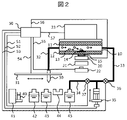
- FIG. 2 is a schematic configuration diagram of an immune analyzer using laser light. show.
- a laser light source 22 and a condensing lens 21 are installed around the bottom of the flow channel 10, and the flow cell flow channel walls 11 and 12 are made of a transparent material.
- the predetermined suction position 14 installed in the channel walls 11 and 12 of the detection section, the laser beam emitted from the lower part of the channel 10 through the laser light source 22 and the condenser lens 21 is condensed.
- the predetermined adsorption position 14 is substantially at a wavelength of light emitted by the labeling substance of the magnetic particle complex adsorbed to the adsorption portion in the flow cell so that the predetermined adsorption position 14 can be irradiated with the laser beam.
- It is preferably made of a material that is highly transparent, for example glass, plastic, or the like.
- the predetermined attraction position 14 may Considering that the magnetic particle composite is adsorbed to the magnetic particle composite, it is preferably made of a material such as gold, platinum, or carbon that is excellent in mechanical strength, corrosion resistance, processing efficiency, and the like. Also, if the laser light does not need to pass through the predetermined attraction position 14, the channel wall 12 need not be made of a transparent material, and materials such as ceramics, metal, and plastic can be used.
- the fluid in the channel 10 is stopped in advance, and the magnet 15 is removed from the position immediately below the channel 10 by the slide mechanism 20 to release the magnetic force in the channel 10 .
- the magnetic particles 13 are held at the predetermined attraction position 14, light emission can be caused by the irradiation of the laser light.
- Measurement can be performed by receiving light emitted from the labeling substance bound to the magnetic particles 13 with the photodetector 23 .
- Controller 50 is connected to valves 36 and 37, pump 35, arm 31, laser light source 22, photodetector 23, slide mechanism 20 by signal lines 51, 52, 53, 54, 55, 56, 57, Each can be controlled independently.
- labeling substance in this modified example may be different from the labeling substance in Example 1 (Fig. 1).
- Specific examples of labeling substances can be appropriately designed by those skilled in the art based on known techniques.
- One analysis cycle consists of a suspension suction period, a magnetic particle capture period, a detection period, a washing period, a reset period, and a preliminary suction period.
- One cycle is started when the suspension container 40 containing the suspension treated by the reaction unit 41 is set at a predetermined position.
- the valve 36 is set open and the valve 37 is set closed.
- a signal from the controller 50 operates the arm 31 to insert the sipper nozzle 30 into the suspension container 40 .
- a signal from the controller 50 causes the pump 35 to perform a certain amount of suction operation.
- Suctioned by the fluid in tube 32 the suspension in suspension container 40 enters tube 32 via sipper nozzle 30 .
- the pump 35 is stopped and the arm 31 is operated to insert the sipper nozzle 30 into the cleaning mechanism 44 .
- the sipper nozzle 30 is cleaned as it passes through the cleaning mechanism 44 .
- the signal from the controller 50 causes the slide mechanism 20 to operate, and the magnet 15 moves to the bottom of the channel 10 .
- a signal from the controller 50 causes the pump 35 to draw at a constant speed.
- the suspension present in tube 32 passes through channel 10 . Since a magnetic field is generated from the magnet 15 in the flow path walls 11 and 12, the magnetic particles 13 contained in the suspension are attracted toward the magnet 15 by the magnetic force and captured (trapped) at the predetermined attraction position 14. adsorption). After a certain period of time has passed, the suspension suction by the pump 3 is stopped.
- the slide mechanism 20 operates and the magnet 15 is moved away from the flow path 10.
- the controller 50 controls the voltage applying means 18 to apply a voltage between the reaction field electrode 16 and the counter electrode 17 in the channel 10 .
- the labeling substance bound to the magnetic particles 13 adsorbed on the reaction field electrode 16 can be caused to electrochemically emit light.
- the emitted light is optionally wavelength-selected by a filter and detected by a photodetector 23, such as a camera or photomultiplier tube.
- the intensity of the detected luminescence is collected by the controller 50 as a signal.
- voltage application is stopped.
- arm 31 is activated to insert sipper nozzle 30 into cleaning mechanism 44 .
- the cleaning liquid sucked from the cleaning liquid container 42 is passed through the channel 10 by suction using the pump 35 .
- the magnet 15 since the magnet 15 is moving away from the flow path 10, the magnetic particles 13 are not held at the predetermined attraction position 14 and are washed away together with the cleaning liquid.
- the valve 36 is closed, the valve 37 is opened, and the pump 35 is discharged.
- the liquid in the pump 35 is discharged to the waste liquid container 45 .
- the buffer is sucked from the buffer container 43 to fill the tube 32 and the channel 10 with the buffer. After a pre-suction period, the next cycle is ready for execution.
- the sample analyzer - a channel for introducing a sample liquid containing magnetic particles 13 bound to a specific substance (substance to be analyzed) into the capture region (predetermined adsorption position 14); - supply means (pump 35) for supplying the sample liquid to the channel; - a trapping means (magnet 15) comprising a magnetic field structure for generating a magnetic field, which attracts the magnetic particles 13 to the trapping area; - measuring means (photodetector 23) for measuring the specific substance adsorbed on the capture zone; - ejection means (pump 35) for ejecting the magnetic particles from the channel after measurement by the measurement means; Prepare.
- the pump 35 is used as both the supply means and the discharge means in this embodiment, individual components may be used for these.
- the sample liquid is a liquid containing a substance to be analyzed, such as a suspension.
- part of a known sample analyzer may be used.
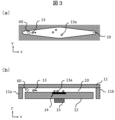
- FIG. 3 is an enlarged view of the configuration near the channel of the immunoassay device, where the direction of flow in the center of the flow cell is the x-axis, the horizontal direction of the cross section perpendicular to the flow is the y-axis, and the vertical direction is the z-axis.
- a coordinate system When a coordinate system is placed, a section on the xy plane (FIG. 3A) and a section on the zx plane (FIG. 3B) are shown.
- the suspension containing the magnetic particles 13 advances in the +z direction along the path formed by the channel walls 11a and 12 in FIG. 3(b) and enters the flow cell.
- the suspension then follows the direction of flow 60 in the channel in the +x direction, and when it reaches the end of the channel 10 it follows the path formed by the channel walls 11b and 12 in the -z direction, It is discharged from the flow cell.
- the suspension is subjected to the magnetic field of the magnet 15, and the magnetic particles 13 are trapped (adsorbed) on the surface of the predetermined attraction position 14 by the magnetic force (attracted magnetic particles 13a).
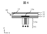
- FIG. 4 is an enlarged view of the vicinity of the flow path when using the magnet structure of this embodiment.
- the magnet 15 includes a plurality of magnets 15a arranged outside the flow path and magnetized in different directions.
- a magnetic field structure is formed by the plurality of magnets 15a. That is, the magnetic field structure comprises a plurality of magnets 15a arranged outside the channel and having different magnetization directions.
- FIG. 4 permanent magnets are used as the magnets 15a, and three magnets 15a of the same size are arranged in a line along the x direction without gaps, and the magnetization direction of each magnet 15a is arranged on the upstream side of the flow path 10. Configurations with -z, +x, and +z from the individual are shown.
- the suspension flows from upstream to downstream. That is, when one magnetic particle 13 flowing with the suspension is at the first position at a first time and at the second position at a second time after the first time, the first position is the second position. and the second position is downstream with respect to the first position. It is an arrangement in which magnetic fluxes are generated in opposite directions between the magnets on the upstream side and the downstream side of the flow path 10 with the magnet in the middle sandwiched therebetween.
- the magnetization direction 61 of the magnet is indicated by arrows so that the S pole ⁇ N pole inside the magnet material (N pole ⁇ S pole outside the magnet such as air) in accordance with general magnetic flux notation. showing.
- General magnet materials can be used for the magnet 15a, and materials such as ferrite magnets, neodymium magnets, samarium-cobalt magnets, alnico magnets, or combinations thereof may be used.
- the plurality of magnets 15a arranged side by side in the form described above may be adhered with an adhesive such as a hardening resin, or may be fixed with a jig made of a non-magnetic material such as plastic or ceramics. good.
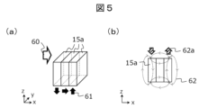
- FIG. 5 shows the magnet structure and generated magnetic flux of this embodiment.
- FIG. 5(a) is a magnet structure showing the configuration of FIG. 4 three-dimensionally.
- FIG. 5(b) is a view showing magnetic flux lines 62 generated along the direction of magnetization 61 in this embodiment in the cross section of the magnet in the zx plane.
- the magnetic flux lines 62 are loop-shaped, and, for example, inside each of the three magnets 15a, the directions of the arrows -z, +x, and +z from the individual arranged on the upstream side of the flow path 10 are the same as the magnetization directions 61. is shown.
- the three magnets 15a each form a rectangular parallelepiped with the same shape, and are arranged so that each face is orthogonal to the x-axis, y-axis or z-axis.
- the specific configuration is not limited to that shown in FIG. 5, and for example, a known Halbach array may be used.
- the magnetic flux lines 62 of the different magnets are superimposed so as to reinforce each other in a partial area outside the magnet.
- the directions of the magnetic flux lines 62 formed by the center magnet of the three magnets 15a and the other two magnets at the ends are aligned, so that magnetic flux vectors are synthesized, Strengthen the generated magnetic flux.
- the strengthened magnetic flux direction 62a in this embodiment, the magnetic fluxes in the -z and +z directions are strengthened on the vertical upper side of the magnet.
- the plurality of magnets 15a are arranged so that the magnetic fluxes generated by each of the two adjacent magnets strengthen each other at least part of the predetermined attraction position 14.
- Magnetic flux constructive means, for example, that the magnetic flux vector reinforces each other. Alternatively, it means that the sign of the z-direction component of the magnetic flux vector is the same.
- the plurality of magnets 15a are such that the magnetic flux density on the flow path side (for example, the magnetic flux density on the magnet surface on the flow path side) is greater than the magnetic flux density on the opposite side of the flow path ( For example, it is arranged so as to be larger than the magnitude of the magnetic flux density on the magnet surface on the opposite side of the flow path).
- the magnetic field applied to the flow path 10 can be strengthened, and the collection rate of the magnetic particles 13 can be increased.
- the collection rate is a value obtained by taking the ratio of the number of magnetic particles 13a adsorbed to the predetermined adsorption position 14 to the number of magnetic particles 13 contained in the sample.
- Non-Patent Document 1 the force that a substance in a magnetic field receives from a magnetic field is generally known from the following equation.
- F the force vector
- E the energy vector
- grad() the operator representing the spatial gradient
- ⁇ 0 the magnetic permeability of the vacuum
- ⁇ the magnetic susceptibility
- B the vector of magnetic flux density
- l the position.
- the magnetic flux density vector B increases, and the force acting on the magnetic particles 13 also increases.
- the configuration of FIG. There is an effect that the collection rate of 13 is improved.
- Fig. 6 (a0) is a single magnet model magnetized to +x, prepared for comparison, and the outside of the magnet is filled with air.
- the analysis results are shown in FIG. 6(a1).
- the surface 70a on which the magnetic field analysis was performed was taken as the internal cross section of the magnet parallel to the zx plane, and the position of the surface 70a in the y direction was taken as the central position of the magnet.
- a distribution was obtained in which the magnetic flux density was high in the air region near the magnet position 71a, and that the magnetic flux density isotropically decreased as the distance from the magnet increased.
- FIG. 6(b0) is a model according to Example 1 of the present invention.
- the magnets were made of the same material and have the same outer dimensions as in FIG. 6(a0), and were arranged as in FIG. Three magnets 15a of the same size are arranged in a line along the x direction without gaps.
- the surface 70b on which the magnetic field analysis was performed was taken as the magnet internal section of the zx plane.
- FIG. 6 (b1) The results of the magnetic field analysis are shown in Fig. 6 (b1). From the analysis results, the magnetic flux density is high in the air region near the magnet position 71b, and the magnetic flux density decreases as the distance from the magnet increases, as the same tendency as the individual magnet model in FIG. 6(a1). I saw the situation. In addition, in FIG. 6(b1), a result was obtained in which the magnetic flux density on the vertical upper surface of the magnet was higher than that on the vertical lower surface.
- the effect of increasing the magnetic flux density and its gradient is, for example, when the outer size of the magnet is 1 to 10 mm, it is extremely strong at a position 0 to 1 mm in the +z direction from the upper surface of the magnet, and the +z direction from the surface of the magnet. It is often seen at a position of 1 mm to 20 mm.
- the magnetic flux density on the opposite side of the flow path 10 on the magnet surface can be reduced, and the magnetic flux density on the flow path 10 side can be increased. It is possible to obtain the effect of drawing out the performance that surpasses the original performance (one individual magnet model in FIG. 6(a1)).
- reducing the magnetic flux density of a specific side surface, such as the vertical lower surface of the magnet in FIG. can be reduced.
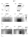
- FIG. 7 shows a magnet model and analysis results when a magnetic field analysis is performed using the same model and conditions as in FIG. 6, focusing on the flow path 10 .
- FIG. 7(a0) is a single magnet model magnetized to +x
- FIG. 7(b0) is a magnet model in which three magnets 15a of this embodiment are arranged without gaps.
- the surfaces 70c and 70d on which the magnetic field analysis was performed were defined in the air region vertically above the upper surfaces 71c and 71d of the magnets.
- the planes 70c, 70d are parallel to the xy plane.
- the magnetic particles 13 flow through the channel 10 and pass over the upper surfaces of the individual magnets.
- the most upstream magnet 15a first magnet
- the next magnet 15a second magnet
- the next magnet 15a third magnet
- a region closer to the first magnet than the second and third magnets a region closer to the second magnet than the first and third magnets
- a region closer to the third magnet than the first and second magnets Each magnet 15a is arranged so as to pass through all the near regions.
- the three magnets 15a are arranged in parallel in the flow direction of the sample liquid in the channel 10, and the sample liquid passes over all the magnets 15a.
- a similar arrangement is possible when using two or four or more magnets 15a.
- FIGS. 7(a1) and 7(b1) show the analysis results of the magnetic flux densities of the respective models. Comparing the magnitudes of the magnetic flux densities, FIG. 7(b1) according to the present embodiment showed a larger value. . It was also confirmed that the change in magnetic flux density in the vicinity of the magnet is also abrupt and the gradient is large. Therefore, using this embodiment, the magnetic flux density and its gradient can be increased.
- FIGS. 7(a2) and 7(b2) focusing on the change in the magnetic flux density in the vicinity of the magnet, for an area where the vertical component of the magnetic flux density is relatively large (that is, an area that is whiter or blacker than the surroundings), for example, the same blackness Comparing the width 72 of the range, FIG. 7B2 according to the present embodiment has a narrower width.
- the magnetic flux density rapidly decreases as the distance increases from the area where the magnetic flux density is high on the upper surface of the magnet, and the area where the magnetic force acting on the magnetic particles is strong and the area where the magnetic force is weak are clearly distinguished.
- the magnetic particles 13 can be attracted to the predetermined attraction position 14 with high density, and at the same time, attraction to places other than the predetermined attraction position 14 can be prevented. Controllability of the adsorption distribution can be enhanced, and uneven adsorption can be prevented.
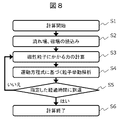
- FIG. 8 shows a flowchart of magnetic particle behavior analysis in flow and magnetic fields.
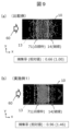
- FIGS. 9(a) and 9(b) are the results of analyzing the magnetic particle adsorption distribution when the magnets of FIGS. 7(a0) and 7(b0) are used in the channel 10, respectively.
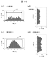
- FIG. 10 is a histogram of the positional distribution of the adsorbed magnetic particles along the x-axis and y-axis, based on the normalized length unit ⁇ .
- 9(a), 10(a1) and 10(a2) show the adsorption distribution of magnetic particles in a single magnet model
- 9(b), 10(b1) and 10(b2) show the magnetism in this embodiment. It is the adsorption distribution of particles.
- FIGS. 10(a1) and (b1), and FIGS. A high collection rate was obtained.
- the rate at which the magnetic particles 13 in the fluid are attracted to the predetermined attraction position 14 is shown as the collection rate. ) was higher in the case of this embodiment.
- FIG. 9 comparing the attraction position of the magnetic particles with respect to the position 71 of the magnet indicated by the dotted line, in the case of the individual magnet model (FIG. 9A), x Magnetic particles are adsorbed to the axial region, and the increase and decrease of the magnetic particles also change smoothly depending on the position.
- FIG. 9B the position 71 of the magnet and the position where many magnetic particles are attracted are almost the same region.
- FIGS. 10(a1) and (b1) These can be confirmed from the x-axis histograms shown in FIGS. 10(a1) and (b1).
- FIGS. 10(a1) and (b1) In the case of a single magnet model (FIG. 10(a1)), a certain number of adsorptions are seen at positions protruding from the specified adsorption position 14, but in the case of this embodiment (FIG. 10(b1)), the specified adsorption position Adsorption at positions beyond 14 was small. In this manner, the present embodiment enhances the controllability of the suction position.
- the predetermined attraction position 14 for example, matching the x-direction dimension of the predetermined attraction position 14 with the position 71 of the magnet, it is possible to further improve the measurement accuracy.
- Example 2 As another example of the present invention, an example using a magnet different from Example 1 is shown. From Example 2 onward, sample analyzers other than the magnet, such as a flow cell, are the same as those in Example 1, and detailed description thereof will be omitted.
- the form described in each embodiment is not limited to shape, size, number, etc., and can be changed without departing from the gist thereof. Examples may be combined.
- the plurality of magnets used in this embodiment has the effect of increasing the collection rate of magnetic particles, or suppresses uneven adsorption by increasing the collection rate of magnetic particles and improving the controllability of the adsorption distribution of magnetic particles.
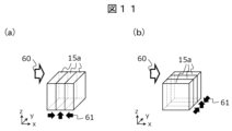
- FIG. 11(a) is an example in which a structure in which three magnets 15a of the same size are arranged in a row without gaps is configured by combining magnets with different magnetization directions.
- the magnetization directions are +x, +z, and -x from the upstream side of the flow path, the magnetic flux density on the upper surface of the magnet increases due to the strengthening of the magnetic flux vectors. increase. As a result, the effect of increasing the collection rate of the magnetic particles 13 is obtained.
- the magnetization directions of the adjacent magnets are basically different from each other by an angle of 90 degrees. Any relative difference can be obtained, except when the relative difference is 0 degrees.
- the absolute value of the relative angle difference may be a value greater than 0 degrees, preferably 45 degrees or more, more preferably 75 degrees or more, and further Preferably, it may be 85 degrees or more. If the absolute value of the relative difference is 90 degrees, it is easy to obtain the effect that the magnetic flux density is higher on one side of the magnet (upper surface of the magnet) than on the opposite side (lower surface of the magnet). Depending on the capture rate and capture distribution, the absolute value of the relative difference may be set to less than 90 degrees.
- the relative difference in the magnetization direction angle between adjacent magnets does not need to be the same. may This makes it possible to control the degree of strengthening of the magnetic flux generated in the flow path 10 and the degree of weakening of the magnetic flux in the space on the opposite side of the flow path 10 .
- FIGS. 5(a) and 11(a) Particularly in embodiments where three or more magnets are arranged in a line, another magnetic flux is placed between the two magnets that generate oppositely directed magnetic fluxes, for example in FIGS. 5(a) and 11(a).
- the structure in which the magnets are placed can increase the points and areas where the magnetic flux builds up.
- a plurality of magnets may be arranged adjacently across the flow path 10.
- a plurality of magnets 15a are arranged in parallel in a direction perpendicular to the direction in which the sample liquid flows in the channel 10, and the sample liquid passes over different magnets.
- the channel (for example, the predetermined attraction position 14 and the space above it) has a right side region, a central region and a left side region in the direction across the channel.
- 15a can be said to be arranged such that the sample liquid passes over different magnets 15a in the right side region, the central region and the left side region.
- the effect of increasing the magnetic flux density on the upper surface of the magnet and the effect of increasing the collection rate of the magnetic particles 13 are obtained.
- the configuration of FIG. 11(b) can control the generated magnetic field distribution in the y direction. Therefore, it is effective in optimizing the distribution of the adsorbed magnetic particles 13a in the y-direction according to the arrangement of the mechanism that causes the luminescence labeling substance to emit light after the magnetic particles 13 are captured.
- the central portion of the flow channel or the side surface of the flow channel (vertically in the flow cell)
- the magnetic particles 13 can be controlled to be sufficiently distributed and adsorbed in the vicinity of the wall surface parallel to ).
- Adjacent arrangement of a plurality of magnets is basically parallel or perpendicular to the flow path 10, but depending on the predetermined attraction position 14 and the shape and arrangement of the mechanism, they may be arranged along other directions. good. For example, in the arrangement and shape of the predetermined attraction position 14 shown in FIG. The placement may be rotated as well.
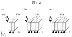
- the number of magnets may be other than three.
- FIG. 12 shows a structure in which two (a), four (b), or five (c) magnets 15a are arranged in a row along the x direction without gaps. is an example of Some of the effects of this embodiment can be obtained regardless of the number of magnets, and six or more magnets may be used. By increasing the number of magnets, the distribution of the generated magnetic field can be precisely controlled. On the other hand, if the number of magnets is small, the effect of this embodiment can be obtained by a simple manufacturing method by omitting adhesion or fixing of the magnets.
- the plurality of magnets it becomes possible to flexibly control the formation of the magnetic field.
- a plurality of magnets may be arranged two-dimensionally within the xy plane.
- the magnetic field in the flow path 10 can be precisely controlled.
- multiple magnets may be arranged three-dimensionally.
- each magnet When a plurality of magnets (for example, three magnets from the first to the third) are arranged three-dimensionally, a region in which the sample liquid is closer to the first magnet than the second magnet and the third magnet in the channel 10, By arranging each magnet so as to pass through both the region closer to the second magnet than the first magnet and the third magnet and the region closer to the third magnet than the first magnet and the second magnet, the upper surface of the magnet It is easy to obtain the effect of increasing the magnetic flux density. However, it does not necessarily have to be arranged to pass through the above three regions, and may be arranged so as to obtain the effect of increasing the magnetic flux density on the upper surface of the magnet.
- the magnetization directions of the two magnets are not limited to the pattern shown in FIG. A pattern in which two are extracted may be used. Furthermore, even when three or more magnets are used, it is possible to use a pattern obtained by extracting arbitrary two adjacent magnets from among the five magnets shown in FIG. can.
- the collection rate of magnetic particles is increased, non-uniform adsorption is suppressed by improving the controllability of the adsorption distribution of magnetic particles, and a sample analysis that realizes both of them. equipment can be provided.
- the plurality of magnets used in this embodiment may have different dimensions.
- two or more magnets with different x-, y-, or z-axis dimensions are arranged in a line along the x direction without gaps.
- FIG. 13 shows a structure in which the magnets arranged on the upstream side of the flow channel are smaller than the magnets arranged on the downstream side of the flow channel (FIGS. 13(a) and (b)), and a vertical magnetic field is generated only on the downstream side of the flow channel.
- FIG. 13(c) shows a structure in which magnets are arranged to cause the magnets to move.
- the magnetic particles first approach the upstream side of the flow path of the magnet due to the process of attracting the magnetic particles 13 from the fluid.
- the number ie the density of the adsorbed magnetic particles, increases.
- the number of particles to be adsorbed on the downstream side of the flow path is relatively small.
- the uniformity of the magnetic particle distribution in is reduced.
- FIGS. 13A and 13B show a structure in which the magnet arranged on the upstream side of the flow channel is smaller than the magnet arranged on the downstream side of the flow channel, and the magnetic field generated on the upstream side of the flow channel is larger on the downstream side of the flow channel.
- the generated magnetic field is larger.
- the magnet on the upstream side of the channel may have a smaller dimension in the direction parallel to the flow direction 60 in the channel (the x direction in FIG. 13(a)), as shown in FIG. Also, as shown in FIG. 13(b), the dimension in the direction (y-direction or z-direction) perpendicular to the flow direction 60 in the channel may be reduced, or a combination thereof may be used.
- the magnetic field generated on the upstream side of the flow path is not weakened (the superiority of the magnet material and placement is improved). without loss), the magnetic field generated downstream of the flow path can be greater than the magnetic field generated upstream of the flow path. This makes it possible to perform measurements in environments where it is more difficult for magnetic particles to be adsorbed, such as high-speed fluids and the flow path 10 having a large cross section.
- the vertical upper surface of the magnet on the upstream side of the flow path and the vertical upper surface of the other magnets do not necessarily need to be arranged on the same plane.
- the vertical upper surface of the magnet on the upstream side of the flow path may be replaced by another magnet. It can be realized by separating the vertical upper surface of the .
- FIG. 13(c) shows a structure using a plurality of (two) magnets 15a with different areas of the surfaces facing the flow path, and in particular, the magnets on the upstream side of the flow path have a large dimension in the x direction.
- a magnet for generating a vertical magnetic field is arranged only on the downstream side of the flow path.
- the plurality of magnets 15a includes a first magnet and a second magnet having a surface area facing the flow path different from that of the first magnet.
- the magnetic particles can be adsorbed on the upstream side with the same distribution and collection rate as when a single magnet is used.
- the magnetic particles that cannot be collected and flow out when using a single magnet are attracted inside the predetermined adsorption position 14 by a strong magnetic field, thereby improving the collection efficiency and Uniformity can be improved.
- the regions "upstream” and “downstream” may be defined with respect to the space of the channel, or may be defined with respect to the bottom surface of the channel (the same applies to other examples). is).
- the plurality of magnets 15a are arranged so that the magnetic flux density on the downstream side is higher than the magnetic flux density on the upstream side in the space in the flow path above the predetermined attraction position 14. can be said to be placed in
- the plurality of magnets 15a has a lower magnetic flux density on the downstream side than the magnetic flux density on the upstream side at the bottom surface of the flow path (for example, the portion constituting the predetermined attraction position 14). It can be said to be arranged to be larger.
- FIG. 14 shows a structure in which three magnets 15a are arranged in a line along the x direction with a gap provided in some of them.
- the gap may be made of air, resin material, ceramics, metal, or the like.
- the gap can be used, for example, to fix arbitrary magnets together using an adhesive or a jig made of ceramics or metal.
- the gap between two adjacent magnets can be sized so that the magnetic fields strengthen each other by synthesizing the magnetic flux vectors. Assuming two adjacent magnets are placed along the x-axis, in order to increase the flux density and gradient, the minimum distance (spacing) between the magnets should be the larger of the x-axis dimensions of both magnets ( Lx) is preferable. That is, the plurality of magnets 15a are preferably arranged such that the interval between two adjacent magnets is smaller than the width (dimension in the arrangement direction) of any of the two adjacent magnets.
- the minimum distance (interval) between magnets is preferably smaller than Lx/2.
- contacting the magnets like the two magnets on the upstream side shown in FIG. 14 is more preferable for increasing the magnetic flux density and gradient.
- each magnet is not limited to a rectangular parallelepiped.
- FIG. 15 shows a structure in which at least one magnet 15a having a shape similar to grooves or unevenness is used, and three magnets 15a are arranged in a row along the x direction.
- FIG. 15(a) shows a structure (FIG. 5(a)) in which three magnets 15a of the same size are arranged in a row without gaps, and a groove is formed in the central portion in the y direction for the magnet located on the upstream side of the flow path. It is the formed form.
- the magnetic field on the side walls can be stronger than in the central portion of the channel.
- Such a structure can improve the controllability of the magnetic particle distribution in the y direction.
- the channel (for example, the predetermined adsorption position 14 and the space above it) has a right side area, a central area, and a left side area in a direction crossing the channel (especially a horizontal crossing direction).
- At least one of the plurality of magnets is such that the magnetic flux density generated by the magnet in the right and left regions is greater than the magnetic flux density generated in the central region by the magnet. It can be said that it is a shape that also becomes larger.
- the magnetic flux density gradient from the magnet to the air region can be increased, which is useful for designing a flow cell that wants to improve the collection rate.
- FIG. 15(b) shows a structure in which three magnets 15a of the same size are arranged in a row without gaps (FIG. 5(a)), and the magnets positioned in the center and downstream of the flow path are provided with recesses and protrusions that mesh with each other. It is the formed form.
- Two adjacent magnets are opposed to each other through surfaces that are shaped to fit each other.
- they face each other and are in contact with each other, but they may be arranged to face each other and spaced apart from each other as shown in FIG.
- the magnet in the center has a shape in which both y-direction sides of the +x-side surface of a rectangular parallelepiped are removed to form a convex in the +x direction, and the volume is smaller than that of the original rectangular parallelepiped.
- the magnet on the downstream side has a concave shape facing the -x direction by protruding both sides of the -x side surface of the rectangular parallelepiped in the -x direction in the y direction, and has a larger volume than the original rectangular parallelepiped. In this way, by increasing the size of the magnet on the downstream side of the flow path, the magnetic field generated on the downstream side of the flow path can be made larger than the magnetic field generated on the upstream side of the flow path. Uniformity of distribution can be improved.
- the grooves or unevenness in a gentle shape (for example, including unevenness of 45 degrees or less), it is possible to suppress abrupt changes in the magnetic field in the area where the magnet is adjacent compared to the case of forming it in a sharp shape, It is useful for designing flow cells to improve uniformity. Since this is particularly related to the distribution at the location where the magnetic particles are attracted, it is desirable to use this form inside the predetermined attraction location 14 .
- the plurality of magnets may include permanent magnets or electromagnets. Heat generation can be suppressed by using a permanent magnet.
- the use of electromagnets can eliminate the magnetic field when it is not needed and suppress the influence of the magnetic field on the surrounding configuration.
- the plurality of magnets may include permanent magnets and electromagnets.
- the plurality of magnets may include permanent magnets made of a first material and permanent magnets made of a second material different from the first material.
- the material is, for example, neodymium, ferrite, samarium cobalt, alnico, etc., but can be appropriately selected based on known techniques. Using magnets of different configurations in this way allows for more flexible control of the magnetic field at each location.
- the present invention is not limited to the above-described embodiments and modifications, and can be modified without departing from the scope of the invention. be. According to the embodiments and modifications of the present invention, it is possible to provide a sample analyzer that increases the collection rate of magnetic particles, suppresses non-uniform adsorption by improving the controllability of the adsorption distribution of magnetic particles, and realizes both of them.
- Direction of magnetization 62 Magnetic flux line 62a... Direction of strengthened magnetic flux 70a, 70b, 70c, 70d... Magnetic field analysis 71, 71a, 71b ... position of the magnet 71c, 71d ... upper surface of the magnet 72 ... width of the region where the vertical component of the magnetic flux density is relatively large
Abstract
磁性粒子の捕集率の増大を実現する試料分析装置を提供する。 試料分析装置は、特定物質に結合した磁性粒子を含む試料液を捕捉領域に導入する流路と、前記流路に前記試料液を供給する供給手段と、磁場を発生させる磁場構造を有し、前記磁場によって前記磁性粒子を前記捕捉領域に吸着させる、捕捉手段と、前記捕捉領域に吸着した前記特定物質を測定する測定手段と、前記測定手段による測定の後に、前記磁性粒子を前記流路から排出する排出手段と、を備える。前記磁場構造は、前記流路の外側に配置され、着磁方向がそれぞれ異なる複数の磁石を備え、前記複数の磁石は、前記流路側の磁束密度が、前記流路とは反対側の磁束密度よりも大きくなるように配置されている。
Description
本発明は試料分析装置に関し、たとえば抗原と抗体の反応を利用するものに関する。
初めに、試料分析の例として、免疫分析について説明する。
免疫検査とは、疾病の診断や病態等の診断を目的に、抗原と抗体の特異的な反応を利用して体液(血漿、血清、尿など)中の抗体や抗原を検出または測定することである。代表的な方法として、ELISA法(Enzyme-Linked Immunosorbent Assay、酵素変易測定法)がある。
ELISA法の典型的な実施過程としては、測定したい抗原に対する抗体(第一抗体)を容器に固相化しておき、そこに血漿、血清、尿などのサンプルを入れ、サンプル中の抗原を第一抗体に結合させる。また、第一抗体に結合した抗原に、標識を結合させた抗体(第二抗体)をさらに結合させる。第一抗体、抗原、第二抗体、標識の結合体を捕集し、標識から発せられる信号を検出することで、サンプル中の抗原の有無や量を測定する。
標識として、例えば、蛍光物質などを用いる。この場合、標識を結合した第二抗体の数、つまり、結合体中の抗原の量に比例して発光が強くなり、蛍光物質の発光を光電子倍増管などで検出することで、サンプル中の抗原を定量することができる。
ELISA法を用いた免疫検査装置の具体的な一例では、固相として磁性粒子が用いられ、第一抗体が磁性粒子の表面に固定化されている。第二抗体には、標識として蛍光色素が結合した物質(発光標識物質)を結合させておく。生体由来の検出物質(抗原)と第一抗体が固定化された磁性粒子とを混合し、抗原抗体反応を生じさせることで、試料に含まれる特定の抗原が第一抗体を介して磁性粒子に結合する。さらに、第二抗体を反応させると、発光標識物質が第二抗体、抗原、第一抗体を介して磁性粒子に結合する。発光標識物質の量は、試料に含まれる検出物質の量、すなわち、抗原の量に依存して増減する。
検出物質が結合した磁性粒子を含む試料を任意の流路に流しながら、流路の途中の所定位置に磁性粒子を吸着させる。吸着した磁性粒子にレーザ等を作用させることにより、磁性粒子に結合した発光標識物質を発光させる。この時の発光強度を検出することで、試料中の検出物質の量すなわち抗原の量を測定することができ、定量的な計測がなされる。
高感度の免疫分析を行うためには、検出物質(抗原)を結合した磁性粒子を、磁石等を用いて特定の場所に吸着させて捕捉し、抗原と結合していない抗体を含む溶液を入れ替える、いわゆるB/F分離(Bound/Free分離、抗原抗体結合体と非結合体の分離)を行う。
分析装置において、磁石等を用いて磁性粒子を所定位置に吸着させる方法として、特許文献1がある。
また、非特許文献1には、物質に対する磁場の作用等が説明されている。
本河、「強磁場と物質科学」、まてりあ、37巻、(1998年)、p926-930
磁石等を用いて磁性粒子を吸着させる際には、発光と発光強度の検出を効率よく行うために、流路壁面上の所定範囲(所定位置)への吸着を行う必要がある。しかし、磁性粒子の所定位置への吸着には、以下のような課題がある。
磁性粒子を所定位置に吸着させるには、磁石等を使用して磁場を発生させ、磁性粒子に磁力を働かせる。しかし、所定位置の範囲内において磁場が弱い箇所がある場合には、磁性粒子を十分に吸着させることができない。すなわち、磁性粒子の捕集率が低くなる。これは特に、流路内の試料液の流速が大きい場合、流路の断面積が大きく磁石の磁場が流路断面全体に影響しにくい場合などで顕著である。ここで、捕集率とは、試料に含まれる磁性粒子のうち、所定位置に捕集できた磁性粒子の割合である。
所定位置の範囲内において磁場を十分に強められた場合であっても、磁性粒子を流体中から吸着させるという工程上、磁性粒子の挙動は、流れの向きに応じて上流側と下流側では非対称になる。また、流路内の壁面付近と中央付近でも、流体挙動が異なるために磁性粒子の挙動が異なる。これらから、磁性粒子の吸着分布が不均一になりうる。
磁性粒子の不均一な吸着分布に関して、例えば、所定位置をはみ出した箇所に吸着した磁性粒子は発光に寄与しないため、計測性能を低下させる。また、所定位置の内部において、吸着した磁性粒子の疎密にばらつきが発生することがあり、疎の箇所は発光感度を低下させることから、この場合も計測性能を低下させる。
加えて、磁性粒子の所定位置をはみ出した吸着や吸着時の疎密のばらつきが起こると、B/F分離時の溶液を入れ替える際に、溶液の界面張力により磁性粒子の凝集部に溶液が残存してしまい、十分なB/F分離が達成できない。
特許文献1では、上流下流の非対称性に起因する不均一な吸着を防止する方法として、磁石を傾けて配置した構造、磁石の端部を切除した構造が示されている。これらのような、上流側で流路と磁石との距離を大きくして磁場を弱くする方法は、均一な磁性粒子の捕集を達成する一方で、本来の磁石の材料機能や磁石配置の優位性を一部損なっている。ゆえに、磁性粒子の捕集率の増大が課題であった。ここで、材料機能とは、例えば材料の残留磁束密度などであり、磁石配置の優位性とは、例えば磁場を発生させたい対象に対して磁石が近い位置にあることである。
上記課題を鑑み、本発明は、磁性粒子の捕集率の増大を実現する試料分析装置の提供を目的とする。
本発明に係る試料分析装置の一例は、
特定物質に結合した磁性粒子を含む試料液を捕捉領域に導入する流路と、
前記流路に前記試料液を供給する供給手段と、
磁場を発生させる磁場構造を有し、前記磁場によって前記磁性粒子を前記捕捉領域に吸着させる、捕捉手段と、
前記捕捉領域に吸着した前記特定物質を測定する測定手段と、
前記測定手段による測定の後に、前記磁性粒子を前記流路から排出する排出手段と、
を備えた試料分析装置において、
前記磁場構造は、前記流路の外側に配置され、着磁方向がそれぞれ異なる複数の磁石を備え、前記複数の磁石は、前記流路側の磁束密度が、前記流路とは反対側の磁束密度よりも大きくなるように配置されている、
ことを特徴とする。
本明細書は本願の優先権の基礎となる日本国特許出願番号2021-135063号の開示内容を包含する。
本発明に係る試料分析装置は、磁性粒子の捕集率を増大させることができる。
以下、本発明の実施例を、図面を用いて説明する。
本実施形態の一つである試料分析装置の例として、ある免疫分析装置に関して説明する。本発明は、免疫分析に限らず、磁性粒子を用いて磁性粒子を捕捉している試料分析装置であれば適用可能であり、DNA、生化学等の分析装置に対しても同様に使用できる。また、以下の説明における方向、向きという言葉は、特に指定がない限り、一般的な物理表現に則って、方向は単に直線の状態を意味し、向きはある始点から一方へ向かっての進行を意味するものとする。
図1に、免疫分析装置の概略構成図を示す。図1において、流路10は、チューブ32およびチューブ33を通して、シッパーノズル30およびポンプ35と接続されている。シッパーノズル30はアーム31により移動可能に取り付けられており、懸濁液容器40、洗浄液容器42、緩衝液容器43がその移動範囲に設置されている。
バルブ36は流路10とポンプ35との間のチューブ33に設けられている。ポンプ35はコントローラ50から、信号線52を通じて制御され、正確な液量の吸引および吐出が可能とされている。ポンプ35はさらにチューブ34を通じて廃液容器45へと続いている。
流路10、流路壁11および12、吸着所定位置14から成る部位を検出部(または、一体の部材としてフローセル)と呼ぶ。フローセルの流路壁11は透明な材料で形成され、内部に溶液が流れる流路10が形成されている。流路壁11および12はたとえばそれぞれ平面状の板を用いて構成することができるが、これに限らない。流路壁11は透明な材料で形成されているため、光を透過するとともに、内部の流動状態が観察可能である。流路壁11の全体が透明である必要は必ずしもなく、光が透過する部分のみ窓として透明であればよい。
流路壁11は、フローセル内の吸着部分に吸着した磁性粒子複合体の標識物質が発する光の波長に対して実質的に透明である材料で製作されるのが好ましく、例えば、ガラス、プラスチックなどで製作されるのが好ましい。
流路10内に設置された吸着所定位置14には、反応場電極16を設置している。また、反応場電極16(吸着所定位置14)から、流路10内の対面周囲に対向電極17が設置されている。さらに、反応場電極16および対向電極17は、リード線19a、19bを介して、電圧印加手段18に接続している。電圧印加手段18は、信号線58によりコントローラ50に接続している。
さらに、磁性粒子の吸着のため、磁場印加手段として磁石15を用いている。磁石15は永久磁石または電磁石である。磁性粒子を吸着させるときは、たとえば磁石15を流路10の直下に移動させる。例えば、水平方向に自由に移動させることができるスライド機構20に磁石15を設置し、磁性粒子を吸着させるときに磁石15を流路10の直下に移動させる。
磁性粒子13は、磁石15の磁場から受ける磁力により、流路10内にて吸着所定位置14に吸着される。吸着所定位置14は、所定の面積を持った面とすると発光測定がしやすい。吸着所定位置14は、本実施例では流路10の底面上に設けることとするが、流路10内の他の面、あるいは、3次元的に配置された複数面にあってもよい。
流路10内を洗浄するときは、たとえば流路10内における磁石15の影響を十分に低減できる位置まで磁石15を移動させることで、十分に洗浄することができる。
スライド機構20は、水平方向への移動を必須とするものではなく、洗浄する際の磁場の影響低減が実現できれば、鉛直方向への移動、あるいは、水平および鉛直の両方向への移動であってもよい。また、磁石15は電磁石でもよく、その場合は、位置の移動ではなく、印加電流によって流路10内における磁場を制御可能である。
コントローラ50は、バルブ36および37、ポンプ35、アーム31、電圧印加手段18、光検出器23、スライド機構20と、信号線51、52、53、54、56、57、58により接続されており、それぞれ独立に制御することができる。
測定においては、コントローラ50によって電圧印加手段18が制御される。それに伴い、流路10内の反応場電極16と対向電極17の間に電圧が印加されると、反応場電極16(吸着所定位置14)上に吸着した磁性粒子13と結合した標識物質を電気化学的に発光させることができる。流路壁11は、光検出器23による測定を可能とするように対向電極17の周囲を透明な材料とすれば、他の部分は透明な材料である必要はない。
反応場電極16および対向電極17の材料は、例えば、金、白金、パラジウム、タングステン、イリジウム、ニッケル及びそれらの合金や炭素材料などで構成することができる。また、反応場電極16および対向電極17は、例えばチタンなどの母材に、前記材料をめっき、スパッタリング等で成膜したものを使用することもできる。
対向電極17を用いた発光方法をとることにより、フローセルに反応場電極16および対向電極17が固定できる。図1の免疫分析装置は、以降の図2にて説明するレーザ光を用いた免疫分析装置と比較して、集光レンズ21、レーザ光源22が不要であることから、レーザ光の位置決めや、吸着所定位置14における透明材料の選定および設置が省略され、装置の簡略化、発光のばらつき抑制が期待できる。
光検出器23には、例えば、カメラや光電子倍増管を用いることができる。
分析対象となる試料とは、血清や尿などの生体由来の物質である。試料が血清の場合、分析されるべき特定成分は、例えば、腫瘍マーカー、抗体、または抗原・抗体複合物、単一タンパク質である。以降の説明では、特定成分は、TSH(甲状腺刺激ホルモン)であるとする。
懸濁液容器40には、前処理過程として、分析対象となる試料がビーズ溶液、試薬と混合されたのち、一定温度(例えば37度)で一定時間反応させたもの(懸濁液)が収容されている。ビーズ溶液とは、粒子状磁性物質をポリスチレンなどのマトリックス材に埋め込んだ磁性粒子13を緩衝液中に分散させた溶液であり、マトリックス材の表面には、ビオチンと結合可能なストレプトアビジンが結合されている。試薬は、磁性粒子13を試料中の特定成分TSHと結合させる物質が含まれており、これには末端をビオチン処理した抗TSH(Thyroid Stimulating Hormone、甲状腺刺激ホルモン)抗体が含まれる。試薬は、分析される特定成分の種類によって異なり、たとえば免疫グロブリン、抗原、抗体またはその他の生物学的物質が使用される。
洗浄液容器42には、流路10およびチューブ32の内部を洗浄するための洗浄液が収容されている。
流路10の形状は、流れに沿った方向の長さ(経路長)と、流れに垂直な断面の厚さ(鉛直方向寸法)および幅(水平方向寸法)を定義した場合に、厚さおよび幅のいずれか大きい方に対して、経路長が2~20倍の長さに形成されることが望ましい。これは、経路を十分に確保することで、流体中の磁性粒子13が、流路10内で広がり、その後、流路10底面上に設けた吸着所定位置14への吸着をしやすくするためである。
流路10内における磁性粒子13の吸着分布は、流路10の近傍に設置された磁石15から受ける磁力と、流体(懸濁液)の流れによる抗力によって決まる。流路10内の磁場は、好ましくは磁束密度の大きさが0.1~0.5Tの強さである。そのときの流体の流速は、好ましくは0.05~0.10m/sである。
磁性粒子13として使用される粒子は、以下に示すような粒子であることが好ましい。(1)常磁性、超常磁性、強磁性、またはフェリ磁性を示す粒子、(2)常磁性、超常磁性、強磁性、またはフェリ磁性を示す粒子を、合成高分子化合物(ポリスチレン、ナイロンなど)、天然高分子(セルロース、アガロースなど)、無機化合物(シリカなど)などの材料に内包した粒子。
また、粒径は0.01~200μmの範囲、さらには1~10μmの範囲が好ましい。比重は1.3~1.5が好ましい。この仕様により、磁性粒子13は、液体内で沈降し難く、懸濁しやすい。粒子の表面には、分析対象物質を特異的に結合する性質を持つ物質、例えば、抗原に特異的に結合する性質を持つ抗体を結合する。
標識物質は、以下に示すような物質であることが好ましい。具体的には、適切な手段により、標識物質を分析対象物質と特異的に結合させ、適切な手段により発光させるという観点で、以下の例が挙げられる。
(1)蛍光免疫測定法で使用される標識物質。例えば、フルオレセインイソチオシアネートで標識した抗体など。
(2)化学発光免疫測定法で使用される標識物質。例えば、アクリジニウムエステルで標識した抗体など。
(3)化学発光酵素免疫測定法で使用される標識物質。例えば、ルミノールやアダマンチル誘導体を発光基質とする化学発光酵素で標識した抗体など。
(1)蛍光免疫測定法で使用される標識物質。例えば、フルオレセインイソチオシアネートで標識した抗体など。
(2)化学発光免疫測定法で使用される標識物質。例えば、アクリジニウムエステルで標識した抗体など。
(3)化学発光酵素免疫測定法で使用される標識物質。例えば、ルミノールやアダマンチル誘導体を発光基質とする化学発光酵素で標識した抗体など。
以上が、本実施例に係る免疫分析装置(図1)の例であるが、機構が異なる変形例に係る装置の一例として、図2に、レーザ光を用いた免疫分析装置の概略構成図を示す。
図2では、流路10の下部周辺に、レーザ光源22、集光レンズ21が設置されており、また、フローセルの流路壁11および12は透明な材料で形成されている。検出部の流路壁11および12内に設置する吸着所定位置14では、流路10の下部からレーザ光源22および集光レンズ21を介して照射されたレーザ光が集光される。その際、吸着所定位置14にレーザ光を照射することができるように、吸着所定位置14は、フローセル内の吸着部分に吸着した磁性粒子複合体の標識物質が発する光の波長に対して実質的に透明である材料で作製されるのが好ましく、例えば、ガラス、プラスチックなどで製作されるのが好ましい。
また、例えば、配置等の工夫により、レーザ光が吸着所定位置14を透過する必要がないようにレーザ光源22、集光レンズ21が構成されている場合には、吸着所定位置14は、その上面に磁性粒子複合体を吸着することを考慮し、金、白金、炭素などの機械強度、耐腐食性、加工効率等に優れた材料で製作することが好ましい。また、レーザ光が吸着所定位置14を透過する必要がない場合には、流路壁12は透明な材料である必要はなく、セラミックス、金属、プラスチックなどの材料を用いることができる。
発光を測定するときには、あらかじめ流路10内の流体を停止させ、さらにスライド機構20により磁石15を流路10直下の位置から排除することで流路10内の磁力を解除する。これにより、磁性粒子13を吸着所定位置14に保持したまま、レーザ光照射による発光を生じさせることができる。磁性粒子13に結合した標識物質からの発光を光検出器23で受光することにより、測定を実施できる。
コントローラ50は、バルブ36および37、ポンプ35、アーム31、レーザ光源22、光検出器23、スライド機構20と、信号線51、52、53、54、55、56、57により接続されており、それぞれ独立に制御することができる。
なお、本変形例(図2)における標識物質は、実施例1(図1)における標識物質とは異なるものを用いてもよい。標識物質の具体例は、当業者が公知技術等に基づいて適宜設計することができる。
図2の免疫分析装置において、コントローラ50、アーム31、スライド機構20、ポンプ35、バルブ36および37、懸濁液容器40、洗浄液容器42、緩衝液容器43、流路10、磁性粒子13、標識物質等は、図1の免疫分析装置の通りである。
次に、本実施例における試料分析装置の動作を、図1の免疫分析装置を例に説明する。
分析の1サイクルは、懸濁液吸引期間、磁性粒子捕捉期間、検出期間、洗浄期間、リセット期間、予備吸引期間からなっている。反応ユニット41で処理した懸濁液の収容された懸濁液容器40が、所定の位置にセットされたところから1サイクルが開始される。
懸濁液吸引期間では、バルブ36は開き、バルブ37は閉じた状態に設定される。コントローラ50の信号により、アーム31が動作し、シッパーノズル30を懸濁液容器40内に挿入する。続いてコントローラ50の信号により、ポンプ35が一定量の吸引動作をする。チューブ32内の流体に吸引されて、懸濁液容器40内の懸濁液がシッパーノズル30を経由してチューブ32内に入る。この状態でポンプ35を停止し、アーム31を動作させてシッパーノズル30を洗浄機構44に挿入する。洗浄機構44を通過時に、シッパーノズル30は洗浄される。
磁性粒子吸着期間では、コントローラ50の信号によりスライド機構20が稼働し、磁石15が流路10の下部へ移動する。コントローラ50からの信号でポンプ35は一定速度で吸引する。その間に、チューブ32内に存在した懸濁液は流路10内を通過する。流路壁11および12内には、磁石15からの磁界が発生しているため、懸濁液に含まれる磁性粒子13は、磁力により磁石15に向かって吸引され、吸着所定位置14に捕捉(吸着)される。一定時間経過後、ポンプ3による懸濁液の吸引を停止する。
検出期間では、スライド機構20が稼働し、磁石15が流路10から遠ざけられる。コントローラ50によって電圧印加手段18が制御され、流路10内の反応場電極16と対向電極17の間に電圧が印加される。これにより、反応場電極16(吸着所定位置14)上に吸着した磁性粒子13と結合した標識物質を電気化学的に発光させることができる。発光は、場合により、フィルターによる波長選択がなされ、カメラや光電子倍増管などの光検出器23により検出される。検出された発光の強度は、信号としてコントローラ50により回収される。一定時間経過後、電圧印加を停止する。検出期間中に、アーム31を稼働し、シッパーノズル30を洗浄機構44に挿入する。
洗浄期間では、ポンプ35を用いて吸引することにより、洗浄液容器42から吸引した洗浄液を流路10内に通過させる。このときは、磁石15は流路10から遠ざかっているため、磁性粒子13は吸着所定位置14に保持されず、洗浄液とともに流し去られる。
リセット期間では、バルブ36を閉じ、バルブ37を開き、ポンプ35を吐出動作する。ポンプ35内の液は、廃液容器45に排出される。
予備吸引期間では、緩衝液容器43から緩衝液を吸引し、チューブ32、流路10内に緩衝液を満たす。予備吸引期間後、次の1サイクルが実行可能になる。
以上説明するように、本実施例に係る試料分析装置は、
‐特定物質(分析対象物質)に結合した磁性粒子13を含む試料液を捕捉領域(吸着所定位置14)に導入する流路と、
‐流路に試料液を供給する供給手段(ポンプ35)と、
‐磁場を発生させる磁場構造を備え、磁場によって磁性粒子13を捕捉領域に吸着させる、捕捉手段(磁石15)と、
‐捕捉領域に吸着した特定物質を測定する測定手段(光検出器23)と、
‐測定手段による測定の後に、磁性粒子を流路から排出する排出手段(ポンプ35)と、
を備える。なお、本実施例では供給手段および排出手段の双方にポンプ35を用いるが、これらに個別の構成要素を用いてもよい。ここで、試料液とは、分析対象物質を含む液体であり、例えば、懸濁液である。
また、図1および図2に関連して上記に説明する構成に代えて、公知の試料分析装置の一部を用いてもよい。
以上の試料分析装置に関して、吸着所定位置14および磁石15の周辺の構造を図3、4、5、6を用いて説明する。以下に説明する構造は、上述の実施例1(図1)および変形例(図2)のいずれにも適用可能である。
図3は免疫分析装置の流路付近の構成の拡大図であり、フローセル中央部における流れの進行方向をx軸、流れに垂直な断面の水平方向をy軸、同鉛直方向をz軸とした座標系を置いた場合に、xy平面の断面(図3(a))とzx平面の断面(図3(b))を示している。
磁性粒子13を含む懸濁液は、図3(b)の流路壁11aと12により形成された経路を+z向きに進み、フローセル内に侵入する。懸濁液は、次いで流路内の流れの向き60の通りに+x向きに進み、流路10の端部に到達すると、流路壁11bと12により形成された経路を-z向きに進み、フローセルから吐出される。この間、懸濁液は磁石15の磁場を受け、磁性粒子13は磁力により吸着所定位置14の表面上に捕捉(吸着)される(吸着した磁性粒子13a)。
図4は、本実施例の磁石構造を用いた際の流路付近の拡大図である。本実施例では、磁石15は、流路の外側に配置され、着磁方向がそれぞれ異なる複数の磁石15aを備える。これら複数の磁石15aによって、磁場構造が形成される。すなわち、磁場構造は、流路の外側に配置され、着磁方向がそれぞれ異なる複数の磁石15aを備える。
図4では、磁石15aとして永久磁石を用い、同じ大きさの磁石15aを3個隙間なくx方向に沿って一列に配置し、各磁石15aの着磁方向を、流路10上流側に配置した個体からそれぞれ-z、+x、+zとした構成を示している。なお、流路10において、懸濁液は上流から下流へと流れる。すなわち、懸濁液とともに流動する一の磁性粒子13が、第1時刻において第1位置にあり、第1時刻より後の第2時刻において第2位置にある場合に、第1位置は第2位置に対して上流であり、第2位置は第1位置に対して下流である。真ん中の磁石を挟み、流路10上流側と下流側の磁石では反対向きの磁束が発生する配置である。
ここで、磁石の着磁の向き61を、一般的な磁束表記に則り、磁石材料内部でS極→N極(空気などの磁石外部ではN極→S極)となるように矢印を用いて示している。
磁石15aには一般的な磁石材料を用いることができ、フェライト磁石、ネオジム磁石、サマリウムコバルト磁石、アルニコ磁石などの材料、あるいはそれらの組合せであってもよい。
また、先述の形態に並置される複数の磁石15a同士は、硬化性樹脂などの接着剤によって接着してもよく、あるいは、プラスチックやセラミックスなどの非磁性材料製の治具などによって固定してもよい。
図5は、本実施例の磁石構造と発生磁束である。この図により本実施例の効果の一つを説明する。図5(a)は、図4の形態を3次元的に示した磁石構造である。この形態において、着磁の向き61に沿って発生した磁束線62を、zx平面の磁石断面にて示した図が図5(b)である。磁束線62はループ状であり、例えば、3個の磁石15aのそれぞれの内部においては、着磁の向き61と同じく、流路10上流側に配置した個体から-z、+x、+zの矢印方向を示している。
本実施例では、3個の磁石15aはそれぞれ同一形状の直方体をなし、各面がx軸、y軸またはz軸と直交するよう配置される。なお、具体的な構成は図5に示すものに限らず、たとえば公知のハルバッハ配列を用いてもよい。
着磁の向き61が異なる磁石15aを並べたことにより、磁石外部の一部の領域において、異なる磁石の磁束線62が互いに強め合うように重なり合う。特に、磁石の鉛直上側では、3個配置した磁石15aのうち中央の磁石と、端部にある他2個の磁石とが作る磁束線62の向きが整合することで、磁束ベクトルが合成され、発生する磁束を強め合う。強められた磁束の向き62aの通り、本実施例では、磁石の鉛直上側において-z、+zの向きの磁束が強められる。
このように、複数の磁石15aは、隣接する2つの磁石それぞれが発生する磁束が、吸着所定位置14の少なくとも一部にて強め合うように配置される。「磁束が強め合う」とは、たとえば磁束のベクトルが強め合うことを意味する。または、磁束のベクトルのうち、z方向の成分の符号が一致することを意味する。
このように、図4および図5の配置では、複数の磁石15aは、流路側の磁束密度(たとえば流路側の磁石面における磁束密度)の大きさが、流路とは反対側の磁束密度(たとえば流路とは反対側の磁石面における磁束密度)の大きさよりも、大きくなるように配置される。
これにより本実施例の効果として、流路10にかかる磁場を強めることができ、磁性粒子13の捕集率を増大させることができる。ここで、捕集率とは、試料に含まれる磁性粒子13の数に対する、吸着所定位置14に吸着した磁性粒子13aの数の割合をとった値である。
なお、非特許文献1によれば、磁場中の物質が磁場によって受ける力は、以下の式にて一般に知られている。
F=-grad(E)=(1/μ0)χB(dB/dl)
ただし、Fは力のベクトルであり、Eはエネルギのベクトルであり、grad()は空間勾配を表す演算子であり、μ0は真空の透磁率であり、χは磁化率であり、Bは磁束密度のベクトルであり、lは位置である。
F=-grad(E)=(1/μ0)χB(dB/dl)
ただし、Fは力のベクトルであり、Eはエネルギのベクトルであり、grad()は空間勾配を表す演算子であり、μ0は真空の透磁率であり、χは磁化率であり、Bは磁束密度のベクトルであり、lは位置である。
強められた磁場では、磁束密度のベクトルBが増大し、磁性粒子13に働く力も増大する。特に、図5の構成においては、-z、+z成分の磁束密度が強められ、鉛直成分の力に対して機能することから、磁性粒子13を流路10の底面に捕捉したい場合において、磁性粒子13の捕集率が向上する効果がある。
磁束密度の増大を確認するため、磁場解析により、磁束密度の大きさ|B|を計算した(図6)(以下、特に断りがない場合、|B|によって磁束密度の大小を示すものとする)。磁場解析は、マクスウェル方程式およびアンペールの法則に基づく汎用磁場解析手法にて実施した。
図6(a0)は、比較のために用意した、+xに着磁した一個体の磁石モデルであり、磁石外部は空気で満たされている。解析結果を図6(a1)に示した。ここでは、磁場解析を実施した面70aを、zx平面に平行な磁石内部断面とし、面70aのy方向の位置は磁石の中央位置とした。解析結果によれば、磁石の位置71a近傍の空気領域では磁束密度が大きく、また、磁石からの距離が大きくなるにつれて、等方的に磁束密度が小さくなる分布が得られた。
図6(b0)は、本発明の実施例1に係るモデルである。磁石は、図6(a0)と同じ材料と外寸、かつ、図5の配置とした。同じ大きさの磁石15aが3個隙間なくx方向に沿って一列に配置されている。磁場解析を実施した面70bを、zx平面の磁石内部断面とした。
磁場解析の結果を図6(b1)に示した。解析結果より、図6(a1)の一個体の磁石モデルと同じ傾向として、磁石の位置71b近傍の空気領域では磁束密度が大きく、磁石からの距離が大きくなるにつれて磁束密度が小さくなる分布をとる様子が見られた。また図6(b1)では、磁石の鉛直上面の磁束密度が鉛直下面よりも大きくなる結果が得られた。
磁束密度の急激な変化から、図6(a1)よりも、図6(b1)の方が磁束密度の勾配(dB/dl)が大きいことも示された。流路10を磁石表面より鉛直上の位置に設置した場合として図6(a1)(b1)に流路10を記載したが、図6(b1)の本実施例の方が、図6(a1)の場合(一個体の磁石)よりも、流路内に大きな磁束密度を発生していることがわかる。本実施例により、磁束密度およびその勾配が増大することが確認された。
磁束密度およびその勾配が増大するという効果は、例えば、磁石外寸が1~10mmであれば、磁石上側の表面から+z方向に0~1mmの位置にて極めて強く見られ、磁石表面から+z方向に1mm~20mmの位置でもよく見られる。ただし、磁石の材料や寸法、あるいは流路の位置や形状に制限はなく、試料分析装置の構成に応じて磁束密度を強めたい位置を適切に設計することで、より高い効果を得ることができる。
本実施例により、磁石表面において流路10とは反対側の磁束密度を小さくし、流路10側の磁束密度を大きくすることができ、目的とする流路10側に絞って、磁石材料が本来持つ性能(図6(a1)の一個体の磁石モデル)を上回る性能を引き出す効果を得る。また、図6(b1)の磁石の鉛直下面のように、特定の側の面の磁束密度を小さくすることは、当該試料分析装置あるいは隣接して配置する別の装置に対して、磁気ノイズを低減できる。
次に、流路10に着目し、本形態における磁性粒子の捕集率、および、付随する別の効果について、図7、8、9、10を用いて述べる。
図7は、流路10に着目し、図6と同様のモデルおよび条件にて、磁場解析を実施した際の磁石モデルと解析結果である。図7(a0)は+xに着磁した一個体の磁石モデルであり、図7(b0)は本実施例の磁石15aが3個隙間なく配置された磁石モデルである。
各磁石の鉛直上に流路10があることを想定し、磁場解析を実施した面70c、70dを、磁石の上側表面71c、71dよりも鉛直上方の空気領域内に定義した。面70c、70dは、xy平面に平行である。
この配置により、図7(b0)の場合には、磁性粒子13は、流路10を流れることで複数の個体の磁石の上面を通過する。3個の磁石15aを用いる本実施例では、最も上流側の磁石15a(第1磁石)、次の磁石15a(第2磁石)、さらに次(すなわち最も下流側)の磁石15a(第3磁石)について、試料液は、第2磁石および第3磁石より第1磁石に近い領域と、第1磁石および第3磁石より第2磁石に近い領域と、第1磁石および第2磁石より第3磁石に近い領域と、をすべて通過するように、各磁石15aが配置される。このように、3個の磁石15aは、流路10において試料液が流れる方向に並列されており、試料液は、すべての磁石15aの上方を通過する。2個または4個以上の磁石15aを用いる場合も同様の配置が可能である。
図7(a1)(b1)は、それぞれのモデルの磁束密度の解析結果であるが、磁束密度の大きさを比較すると、本実施例に係る図7(b1)の方が大きな値を示した。また、磁石近傍における磁束密度の変化も急激であり、勾配が大きいことも確認された。ゆえに、本実施例を用いることで、磁束密度およびその勾配を増大させることができる。
この傾向は、図7(a2)(b2)に示した磁束密度の鉛直成分においても見られ、本実施例の形態を用いることで、磁性粒子に働く鉛直方向の力を増大させることが確認された。吸着所定位置14を流路10の底面上に設ける場合、流路10内の磁性粒子13は鉛直下向きの磁力によって吸着所定位置14に吸着することから、磁性粒子13の吸着を促進することができる。
ここで、図7(a2)(b2)において、磁石近傍の磁束密度の変化に着目し、磁束密度の鉛直成分が比較的大きな領域(すなわち、周囲より白いまたは黒い領域)について、たとえば同じ黒さ範囲の幅72を比較すると、本実施例に係る図7(b2)の方が狭い幅である。本実施例では、磁石上面の磁束密度が大きな領域から、距離が離れるにつれて急激に磁束密度が減少し、磁性粒子に働く磁力が強い領域と弱い領域が明確に区分される。これにより、吸着所定位置14に磁性粒子13を高密度に吸着させることができ、また同時に、吸着所定位置14以外の場所への吸着を防止できる。吸着分布の制御性を高めることができ、不均一な吸着を防止できる。
本実施例の効果を確かめるために、磁性粒子の挙動を高精度に解析することができる数値シミュレーターを用いて吸着過程を解析した。図8は、流れ場および磁場中の磁性粒子挙動解析のフローチャートを示す。
計算が開始されると(S1)、汎用流体解析ソフトを用いて、流路10内の流体解析を行い、速度場、圧力場を求める。同時に、別途、汎用磁場解析ソフトを用いて、磁石周りの磁場を求める。次に、粒子挙動解析プログラムが流れ場、磁場のデータを読み込み(S2)、各粒子位置における流れ場、磁場の値を用いて粒子にかかる力を計算することができる(S3)。ここで、粒子にかかる力として、流れから受ける力、重力、磁石から受ける力を評価している。各粒子に対して、ニュートンの運動方程式を逐次解くことにより、粒子挙動解析を行って磁性粒子の位置を更新しながら(S4)、磁性粒子の挙動を解析した。指定した経過時間に到達するまで計算を繰り返し(S5)、到達すると計算を終了した(S6)。
図9(a)(b)はそれぞれ、流路10における図7(a0)(b0)の磁石を用いた場合の、磁性粒子の吸着分布を解析した結果である。また図10は、規格化した長さ単位σのもと、吸着した磁性粒子の位置分布を、x軸、y軸に沿ってヒストグラム化したものである。図9(a)、図10(a1)(a2)は一個体の磁石モデルでの磁性粒子の吸着分布、図9(b)、図10(b1)(b2)は、本実施例での磁性粒子の吸着分布である。
図9(a)と(b)、図10(a1)と(b1)、図10(a2)と(b2)にて吸着した磁性粒子の数を比較し、本実施例の方が、磁性粒子の捕集率が大きい結果が得られた。ここで、図9では、流体中の磁性粒子13が吸着所定位置14に吸着した割合を捕集率として示しており、図9(a)の一個体の磁石の場合よりも、図9(b)の本実施例の場合の方が、高い数値であった。
図9にて、点線で示した磁石の位置71に対して、磁性粒子の吸着位置を見比べると、一個体の磁石モデルの場合(図9(a))は、磁石の位置71よりも広いx軸領域に磁性粒子が吸着しており、その増減も位置によってなだらかに変化している。他方で、本実施例の場合(図9(b))では、磁石の位置71と、磁性粒子が多く吸着している位置がほとんど同じ領域である。
これらは、図10(a1)と(b1)に示したx軸のヒストグラムより確認することができる。一個体の磁石モデルの場合(図10(a1))は、吸着所定位置14をはみ出した位置での吸着も一定数見られるが、本実施例の場合(図10(b1))では吸着所定位置14をはみ出した位置での吸着は少数であった。このように、本実施例により吸着位置の制御性が高められる。
さらに言えば、例えば、吸着所定位置14のx方向の寸法を磁石の位置71と合わせるなど、吸着所定位置14の形状や寸法を適正に設計することで、さらなる測定精度の向上が可能である。
以上の本実施例により、磁性粒子の捕集率の増大、磁性粒子の吸着分布の制御性向上による不均一な吸着の抑制、またはそれらの両立を実現する試料分析装置を提供できる。
本発明の他の実施例として、実施例1とは異なる磁石を用いた実施例を示す。実施例2以降では、フローセルなどの磁石以外の試料分析装置については、実施例1と同様であり、詳細な説明は割愛する。各実施例に記載されている形態は、形状、寸法、数等に限定されるものではなく、その要旨を逸脱しない範囲で変更可能であり、また、先述あるいは後述の実施例を含めて複数の実施例を組み合わせても構わない。
本実施例で用いる複数の磁石は、磁性粒子の捕集率が増大する効果、または、磁性粒子の捕集率の増大と磁性粒子の吸着分布の制御性向上による不均一な吸着の抑制を両立する効果が得られる形態であれば、図5とは着磁方向が異なる磁石の組み合わせであっても構わない。
図11(a)は、同じ大きさの磁石15aが3個隙間なく一列に配置した構造を、異なる着磁方向の磁石の組み合わせによって構成した例である。図11(a)のように、流路上流側の個体から、+x、+z、-xの着磁方向で配置した場合であっても、磁束ベクトルの強め合いにより、磁石上面での磁束密度が増大する。これにより、磁性粒子13の捕集率が増大する効果を得る。
本実施例では、隣接する磁石同士の着磁方向が相対的に90度異なる角度であることを基本とするが、磁束ベクトルの強め合いは、隣接する磁石同士の着磁方向が同一(角度の相対差が0度)である場合を除いて、任意の相対差で得ることができる。角度の相対差を-90度~+90度の範囲で定義すると、角度の相対差の絶対値は、0度より大きい値であればよく、好ましくは45度以上、より好ましくは75度以上、さらに好ましくは85度以上であってもよい。相対差の絶対値を90度とすると、磁石の片面(磁石上面)の方がその対面(磁石下面)よりも磁束密度が大きいという効果を得やすいが、吸着所定位置14の形状や目標とする捕集率及び捕捉分布によっては、相対差の絶対値を90度未満に設定してもよい。
また、磁石が3個以上の場合には、隣接する磁石同士の着磁方向の角度の相対差は、すべて同一とする必要はなく、複数ある隣接箇所において、異なる相対差となる角度を併用してもよい。これにより、流路10内に発生する磁束の強め合いの程度、および、流路10とは反対側の空間における磁束の弱め合いの程度を制御できる。
とくに、3個またはそれ以上の磁石を一列に配置した実施形態では、図5(a)や図11(a)を例とするように、反対向きの磁束が発生する2磁石の間に別の磁石を配置する構造により、磁束が強め合う箇所および領域を増大できる。
なお、上記の着磁方向の相対差の変形例は、本実施例に限らず、他の実施例にも適用可能である。
複数の磁石は、流路10を横断する隣接配置であってもよく、例えば、図11(b)の通り、同じ大きさの磁石15aが3個隙間なくy方向に沿って一列に配置した構造であってもよい。複数の磁石15aは、流路10において試料液が流れる方向と垂直な方向に並列されており、試料液がそれぞれ異なる磁石の上方を通過する。
すなわち、この場合には、流路(たとえば吸着所定位置14およびその上方の空間)は、流路を横切る方向に、右側部領域、中央領域および左側部領域を有するということができ、複数の磁石15aは、試料液が、右側部領域、中央領域および左側部領域において、それぞれ異なる磁石15aの上方を通過するように配置されるということができる。
この形態においても、磁石上面での磁束密度が増大する効果、および、磁性粒子13の捕集率が増大する効果を得る。また、特に、図11(b)の構成によりy方向の発生磁場分布を制御できる。従って、磁性粒子13の捕捉後に発光標識物質を発光させる機構の配置形態に応じて、吸着した磁性粒子13aの分布をy方向に対して適正化させる際に有効である。例えば、反応場電極16と対向電極17を用いた機構において、対向電極17をy方向に沿って配置させる場合に、流路中央部、あるいは、流路の側面(フローセル内の、鉛直で流路と平行な壁面)付近に、磁性粒子13が十分に分布して吸着するように制御できる。
複数の磁石の隣接配置は、流路10に対して平行、あるいは、垂直な方向を基本とするが、吸着所定位置14や機構の形状や配置によっては、その他の方向に沿って配置してもよい。例えば、図9に示した吸着所定位置14の配置および形状において、吸着所定位置14を、流路の中心点を中心としてxy平面内で45度回転させた配置を用いる場合、複数の磁石15aの配置も同様に回転させてもよい。
磁石の個数は3個以外でもよく、例えば、図12は、磁石15aを2個(a)、4個(b)、または5個(c)、隙間なくx方向に沿って一列に配置した構造の例である。本実施例の効果の一部は、磁石の個数に限らずに得ることができ、6個以上の磁石を用いても構わない。磁石の個数を増加させることで、発生する磁場の分布を緻密に制御できる。他方で、磁石の個数が少数であれば、磁石同士の接着や固定の省略等により、簡易な製造方法により本実施例の効果を得ることができる。
とくに、複数の磁石として3つ以上の磁石を含むようにすると、磁場の形成を柔軟に制御することが可能になる。3個以上磁石を用いた場合、一列での配置は必須ではなく、例えば、複数の磁石をxy平面内で2次元的に配置しても構わない。x、y方向への並置をそれぞれ複数の磁石によって行った場合、流路10内の磁場を緻密に制御することができる。同様に、複数の磁石を3次元的に配置しても構わない。複数の磁石(例えば、第1~第3までの3個)を3次元的に配置した場合、試料液が流路10内において、第2磁石および第3磁石より第1磁石に近い領域と、第1磁石および第3磁石より第2磁石に近い領域と、第1磁石および第2磁石より第3磁石に近い領域と、をすべて通過するように各磁石が配置されることにより、磁石上面で磁束密度が増大する効果を得やすい。しかしながら、必ずしも先の3領域を通過する配置でなくてもよく、磁石上面で磁束密度が増大する効果が得られる配置であればよい。
また、2個の磁石のみを用いる場合には、2個の磁石の着磁方向は、図12(a)に示すパターンに限らず、図12(c)の5個のうちから任意の隣接する2個を抜き出したパターンを用いてもよい。さらに、3個以上の磁石を用いる場合にも、隣接する2個の磁石の着磁方向として、図12(c)の5個のうちから任意の隣接する2個を抜き出したパターンを用いることができる。
以上により、実施例1と異なる磁石の配置を用いて、磁性粒子の捕集率の増大、磁性粒子の吸着分布の制御性向上による不均一な吸着の抑制、およびそれらの両立を実現する試料分析装置を提供できる。
本実施例で用いる複数の磁石は、それぞれ異なる寸法の磁石であってもよく、例えば、x、yまたはz軸の寸法が異なる磁石を2個以上、隙間なくx方向に沿って一列に配置してもよい。図13は、流路上流側に配置した磁石が流路下流側に配置した磁石よりも小さい構造(図13(a)(b))、および、流路下流側にのみ鉛直方向の磁場を発生させる磁石を配置した構造(図13(c))の例である。
実施例1で示した試料分析装置では、磁性粒子13を流体中から吸着させるという工程上、磁性粒子は先に磁石の流路上流側に接近することとなり、流路上流側で吸着される粒子数、つまりは吸着した磁性粒子の密度が大きくなる。その結果、例えば、一個体の磁石を用いた場合(図6(a)、図7(a))では、流路下流側で吸着される粒子が相対的に少なくなることから、吸着所定位置14における磁性粒子分布の均一性が低下する。
図13(a)(b)は、流路上流側に配置した磁石が流路下流側に配置した磁石よりも小さい構造であり、流路上流側で発生する磁場よりも、流路下流側で発生する磁場の方が大きい。これにより、一個体の磁石を用いた場合で発生しやすい流路上下間での均一性の低下を抑制し、吸着所定位置14における磁性粒子分布の均一性を向上させることができる。
このときの流路上流側の磁石は、図13(a)のように、流路内の流れの向き60と平行な方向(図13(a)ではx方向)寸法を小さくしてもよく、また、図13(b)のように、流路内の流れの向き60とは垂直な方向(y方向あるいはz方向)の寸法を小さくしてもよく、またそれらの組み合わせであってもよい。
流路上流側の磁石の鉛直上側表面と、他の磁石の鉛直上側表面を同一平面上に配置することで、流路上流側で発生する磁場を弱めることなく(磁石材料や配置の優位性を損なうことなく)、流路上流側で発生する磁場よりも、流路下流側で発生する磁場を大きくすることができる。これにより、例えば、高速な流体、大面積の断面を持った流路10など、磁性粒子の吸着がより困難な環境での計測を実現できる。
ただし、流路上流側の磁石の鉛直上側表面と、他の磁石の鉛直上側表面は、必ずしも同一平面上に配置する必要はない。例えば、磁性粒子分布の均一性向上のために、流路下流側で発生する磁場を流路上流側よりもより大きくしたい場合には、流路上流側の磁石の鉛直上側表面を、他の磁石の鉛直上側表面よりも流路から遠ざかる位置に離すことで実現できる。
図13(c)は、流路との対向面の面積が異なる複数(2個)の磁石15aを用いた構造であり、特に、流路上流側の磁石にx方向の寸法が大きいものを使用し、また、流路下流側にのみ鉛直方向の磁場を発生させる磁石を配置した構造である。複数の磁石15aは、第1磁石と、この第1磁石とは流路との対向面の面積が異なる第2磁石と、を備える。この構造は、磁束の強め合いが流路下流側のみで発生するため、流路上流側よりも下流側の磁束密度を大きくすることができる。流路上流側の磁石の寸法が大きいことにより、上流側では一個体の磁石を用いた場合と同様の分布および捕集率で磁性粒子を吸着させることができる。他方で、流路下流側では、一個体の磁石を用いた場合には捕集できずに流出してしまう磁性粒子を、強い磁場によって吸着所定位置14の内部に吸着させ、捕集率向上ならびに均一性向上を実現できる。
上述の実施例3において、「上流」および「下流」という領域は、流路の空間に対して定義されてもよいし、流路の底面について定義されてもよい(他の実施例についても同様である)。空間に対して定義される場合には、複数の磁石15aは、吸着所定位置14の上方の流路内の空間において、上流側の磁束密度よりも、下流側の磁束密度の方が大きくなるように配置されるということができる。一方、底面について定義される場合には、複数の磁石15aは、流路の底面(たとえば吸着所定位置14を構成する部分)において、上流側の磁束密度よりも、下流側の磁束密度の方が大きくなるように配置されるということができる。
本実施例で用いる複数の磁石について、各磁石間には隙間があってもよい。図14は、磁石15aを3個、一部に隙間を設けて、x方向に沿って一列に配置した構造である。この際、隙間は、空気、樹脂材料、セラミックス、金属等で構成してよい。隙間は、例えば、接着剤、あるいは、セラミックス製や金属製の治具による任意の磁石同士の固定などに使用することができる。
隣接する2つの磁石同士の隙間は、磁束ベクトルの合成により磁場が強め合う寸法とすることができる。隣接する2つの磁石をx軸に沿って配置したと仮定して、磁束密度および勾配を増大させるためには、磁石同士の最小距離(間隔)は、双方の磁石のx軸寸法の大きい方(Lxとする)よりも小さい方が好ましい。すなわち、複数の磁石15aは、隣接する2つの磁石の間隔が、当該隣接する2つの磁石いずれの幅(配列方向の寸法)よりも小さくなるように配置することが好ましい。
同様の観点から、磁石同士の最小距離(間隔)は、Lx/2よりも小さい方がより好ましい。とくに、図14に示す上流側2個の磁石のように、磁石同士を接触させることが、磁束密度および勾配を増大させるためにはさらに好ましい。
本実施例で用いる複数の磁石において、各磁石の形状は直方体に限るものではなく、例えば、溝、凹凸などの特異な部位を含む形状であってもよい。図15は、溝あるいは凹凸に類する形状を持つ磁石15aを少なくとも1個以上使用し、磁石15aを3個、x方向に沿って一列に配置した構造である。
図15(a)は、同じ大きさの磁石15aが3個隙間なく一列に配置した構造(図5(a))において、流路上流側に位置する磁石について、y方向の中央部に溝を形成した形態である。溝に対応する体積だけ流路上流側の磁石を小さくすることで、流路上流側で発生する磁場よりも、流路下流側で発生する磁場を大きくすることができ、磁性粒子分布の均一性を向上させることができる。また、y方向の中央部に、z方向に延びる溝を形成することにより、流路中央部よりも側壁側(y方向両側)での磁場を強めることができる。このような構造により、y方向での磁性粒子分布の制御性を向上できる。
図15(a)の例では、流路(たとえば吸着所定位置14およびその上方の空間)は、流路を横切る方向(とくに水平に横切る方向)に、右側部領域、中央領域および左側部領域を有するということができ、複数の磁石のうち少なくとも1つ(上流側の磁石)は、その磁石によって右側部領域および左側部領域に発生する磁束密度が、その磁石によって中央領域に発生する磁束密度よりも大きくなる形状であるということができる。
溝あるいは凹凸を鋭利な形状(たとえば90度の凹凸を含む)で形成することで、磁石から空気領域への磁束密度勾配を増大でき、捕集率を向上したいフローセルの設計に有用である。特に、捕集率向上の観点から、例えば、吸着所定位置14とそれ以外の領域の界面付近で本実施例の構成を用いることが望ましい。
図15(b)は、同じ大きさの磁石15aが3個隙間なく一列に配置した構造(図5(a))において、中央および流路下流側に位置する磁石について、互いに篏合する凹凸を形成した形態である。隣接する2つの磁石が、互いに篏合する形状の面を介して対向する。なお、図15(b)の例では、対向して接触しているが、対向した配置で図14のように離間して配置されてもよい。
中央の磁石は、直方体の+x側の面のy方向両側を除去して+xの向きに凸を形成した形状であり、元の直方体より体積が小さい。下流側の磁石は、直方体の-x側の面のy方向両側を-x側に突出させることによって、-xの向きに面した凹を形成した形状であり、元の直方体より体積が大きい。このように、流路下流側の磁石を大きくすることで、流路上流側で発生する磁場よりも、流路下流側で発生する磁場を大きくすることができ、x軸方法に対して磁性粒子分布の均一性を向上させることができる。
溝あるいは凹凸を、なだらかな形状(例えば45度以下の凹凸を含む)で形成することで、鋭利な形状で形成した場合に比べ、磁石が隣接する領域での急激な磁場の変化を抑制でき、均一性を向上したいフローセルの設計に有用である。これは特に、磁性粒子が吸着した箇所での分布にかかわることから、吸着所定位置14の内部で本形態を用いることが望ましい。
上述の実施例および変形例において、複数の磁石は、永久磁石を含んでもよいし、電磁石を含んでもよい。永久磁石を用いると、発熱を抑制することができる。電磁石を用いると、磁場が不要な場合には磁場を消去し、磁場による周辺の構成への影響を抑制することができる。
また、複数の磁石は、永久磁石および電磁石を含んでもよい。または、複数の磁石は、第1材料からなる永久磁石と、第1材料とは異なる第2材料からなる永久磁石とを含んでもよい。材料はたとえばネオジム、フェライト、サマリウムコバルト、アルニコ等であるが、公知技術等に基づいて適宜選択可能である。このように異なる構成の磁石を用いることにより、各位置における磁場のより柔軟な制御が可能になる。
以上の実施例により、本発明の実施例および変形例を具体的に説明したが、本発明は上述の実施例および変形例に限定されるものではなく、その要旨を逸脱しない範囲で変更可能である。本発明の実施例および変形例により、磁性粒子の捕集率の増大、磁性粒子の吸着分布の制御性向上による不均一な吸着の抑制、およびそれらの両立を実現する試料分析装置を提供できる。
10…流路
11、12…流路壁
11a、11b…流路壁
13…磁性粒子
13a…吸着した磁性粒子
14…吸着所定位置(補足領域)
15、15a…磁石
16…反応場電極
17…対向電極
18…電圧印加手段
19a、19b…リード線
20…スライド機構
21…集光レンズ
22…レーザ光源
23…光検出器
30…シッパーノズル
31…アーム
32、33、34…チューブ
35…ポンプ
36、37…バルブ
40…懸濁液容器
41…反応ユニット
42…洗浄液容器
43…緩衝液容器
44…洗浄機構
45…廃液容器
50…コントローラ
51、52、53、54、55、56、57、58…信号線
60…流路内の流れの向き
61…着磁の向き
62…磁束線
62a…強められた磁束の向き
70a、70b、70c、70d…磁場解析を実施した面
71、71a、71b…磁石の位置
71c、71d…磁石の上側表面
72…磁束密度の鉛直成分が比較的大きな領域の幅
本明細書で引用した全ての刊行物、特許および特許出願はそのまま引用により本明細書に組み入れられるものとする。
Claims (14)
- 特定物質に結合した磁性粒子を含む試料液を捕捉領域に導入する流路と、
前記流路に前記試料液を供給する供給手段と、
磁場を発生させる磁場構造を有し、前記磁場によって前記磁性粒子を前記捕捉領域に吸着させる、捕捉手段と、
前記捕捉領域に吸着した前記特定物質を測定する測定手段と、
前記測定手段による測定の後に、前記磁性粒子を前記流路から排出する排出手段と、
を備えた試料分析装置において、
前記磁場構造は、前記流路の外側に配置され、着磁方向がそれぞれ異なる複数の磁石を備え、前記複数の磁石は、前記流路側の磁束密度が、前記流路とは反対側の磁束密度よりも大きくなるように配置されている、
ことを特徴とする試料分析装置。 - 請求項1に記載の試料分析装置において、
前記複数の磁石は、隣接する2つの磁石それぞれが発生する磁束が、前記捕捉領域の少なくとも一部にて強め合うように配置されている、
ことを特徴とする試料分析装置。 - 請求項1に記載の試料分析装置において、
前記複数の磁石は、前記流路において前記試料液が流れる方向に並列されており、前記試料液は、すべての前記複数の磁石の上方を通過することを特徴とする試料分析装置。 - 請求項1に記載の試料分析装置において、
前記複数の磁石は、前記流路において前記試料液が流れる方向と垂直な方向に並列されており、前記試料液がそれぞれ異なる磁石の上方を通過することを特徴とする試料分析装置。 - 請求項1に記載の試料分析装置において、
前記複数の磁石は、前記捕捉領域の上方の前記流路内の空間において、前記流路の上流側の磁束密度よりも、前記流路の下流側の磁束密度の方が大きくなるように配置されている
ことを特徴とする試料分析装置。 - 請求項1に記載の試料分析装置において、前記複数の磁石は3つ以上の磁石を含むことを特徴とする試料分析装置。
- 請求項1に記載の試料分析装置において、
前記複数の磁石は、前記捕捉領域を構成する前記流路の底面において、前記流路の上流側の磁束密度よりも、前記流路の下流側の磁束密度の方が大きくなるように配置されている
ことを特徴とする試料分析装置。 - 請求項1に記載の試料分析装置において、
前記複数の磁石は、隣接する2つの磁石の間隔が、当該隣接する2つの磁石いずれの幅よりも小さくなるように配置されている、
ことを特徴とする試料分析装置。 - 請求項1に記載の試料分析装置において、
前記複数の磁石は、隣接する2つの磁石が、互いに篏合する形状の面を介して対向するように配置されている
ことを特徴とする試料分析装置。 - 請求項5に記載の試料分析装置において、
前記流路は、前記流路を横切る方向に、右側部領域、中央領域および左側部領域を有し、
前記複数の磁石のうち少なくとも1つは、その磁石によって前記右側部領域および前記左側部領域に発生する磁束密度が、その磁石によって前記中央領域に発生する磁束密度よりも大きくなる形状である、
ことを特徴とする試料分析装置。 - 請求項1に記載の試料分析装置において、前記複数の磁石は永久磁石を含むことを特徴とする試料分析装置。
- 請求項1に記載の試料分析装置において、前記複数の磁石は電磁石を含むことを特徴とする試料分析装置。
- 請求項1に記載の試料分析装置において、前記複数の磁石は、
‐永久磁石および電磁石を含むか、または、
‐第1材料からなる永久磁石と、第2材料からなる永久磁石とを含む、
ことを特徴とする試料分析装置。 - 請求項1に記載の試料分析装置において、
前記複数の磁石は、第1磁石と、前記第1磁石とは前記流路との対向面の面積が異なる第2磁石と、を備えることを特徴とする試料分析装置。
Priority Applications (1)
| Application Number | Priority Date | Filing Date | Title |
|---|---|---|---|
| CN202280048331.5A CN117616286A (zh) | 2021-08-20 | 2022-07-19 | 试样分析装置 |
Applications Claiming Priority (2)
| Application Number | Priority Date | Filing Date | Title |
|---|---|---|---|
| JP2021135063A JP2023029014A (ja) | 2021-08-20 | 2021-08-20 | 試料分析装置 |
| JP2021-135063 | 2021-08-20 |
Publications (1)
| Publication Number | Publication Date |
|---|---|
| WO2023021904A1 true WO2023021904A1 (ja) | 2023-02-23 |
Family
ID=85240478
Family Applications (1)
| Application Number | Title | Priority Date | Filing Date |
|---|---|---|---|
| PCT/JP2022/027987 WO2023021904A1 (ja) | 2021-08-20 | 2022-07-19 | 試料分析装置 |
Country Status (3)
| Country | Link |
|---|---|
| JP (1) | JP2023029014A (ja) |
| CN (1) | CN117616286A (ja) |
| WO (1) | WO2023021904A1 (ja) |
Citations (5)
| Publication number | Priority date | Publication date | Assignee | Title |
|---|---|---|---|---|
| JP2004535292A (ja) * | 2001-06-27 | 2004-11-25 | ビオメリュー・ソシエテ・アノニム | 磁気微粒子の湿式分離の方法、素子及び装置 |
| JP2013238420A (ja) * | 2012-05-11 | 2013-11-28 | Hitachi High-Technologies Corp | 試料分析装置及び試料分析方法 |
| JP2019152655A (ja) * | 2018-03-03 | 2019-09-12 | ユーチェン ゾォウYuchen Zhou | 生物学的実体を分離するための方法および装置 |
| WO2020061696A1 (en) * | 2018-09-28 | 2020-04-02 | Octane Biotech Inc. | Magnetic separation |
| JP2021135063A (ja) | 2020-02-21 | 2021-09-13 | 花王株式会社 | 複合シートの製造方法 |
-
2021
- 2021-08-20 JP JP2021135063A patent/JP2023029014A/ja active Pending
-
2022
- 2022-07-19 WO PCT/JP2022/027987 patent/WO2023021904A1/ja active Application Filing
- 2022-07-19 CN CN202280048331.5A patent/CN117616286A/zh active Pending
Patent Citations (5)
| Publication number | Priority date | Publication date | Assignee | Title |
|---|---|---|---|---|
| JP2004535292A (ja) * | 2001-06-27 | 2004-11-25 | ビオメリュー・ソシエテ・アノニム | 磁気微粒子の湿式分離の方法、素子及び装置 |
| JP2013238420A (ja) * | 2012-05-11 | 2013-11-28 | Hitachi High-Technologies Corp | 試料分析装置及び試料分析方法 |
| JP2019152655A (ja) * | 2018-03-03 | 2019-09-12 | ユーチェン ゾォウYuchen Zhou | 生物学的実体を分離するための方法および装置 |
| WO2020061696A1 (en) * | 2018-09-28 | 2020-04-02 | Octane Biotech Inc. | Magnetic separation |
| JP2021135063A (ja) | 2020-02-21 | 2021-09-13 | 花王株式会社 | 複合シートの製造方法 |
Non-Patent Citations (1)
| Title |
|---|
| MOTOKAWA: "High Magnetic Field and Material Science", MATERIAL JAPAN, vol. 37, 1998, pages 926 - 930 |
Also Published As
| Publication number | Publication date |
|---|---|
| JP2023029014A (ja) | 2023-03-03 |
| CN117616286A (zh) | 2024-02-27 |
Similar Documents
| Publication | Publication Date | Title |
|---|---|---|
| EP2581746B1 (en) | Sample analysis device and sample analysis method | |
| JP3996644B2 (ja) | 外部及び内部勾配を有する磁気分離 | |
| US10444125B2 (en) | Devices and methods for separating magnetically labeled moieties in a sample | |
| JP6092910B2 (ja) | 磁性粒子を作動させるためのバイオセンサー・システム | |
| WO1997046882A9 (en) | Magnetic separation employing external and internal gradients | |
| JP6313977B2 (ja) | 試料分析装置及び試料分析方法 | |
| JP4482035B2 (ja) | 粒子に基づく結合アッセイ法 | |
| US20110050215A1 (en) | System for applying magnetic forces to a biosensor surface by mechanically moving at least one magnet | |
| RU2520607C2 (ru) | Приведение в действие импульсным магнитным полем для чувствительных анализов | |
| WO2023021904A1 (ja) | 試料分析装置 | |
| CN108918500B (zh) | 基于免疫磁珠标记的sers分选方法 | |
| JP2006218442A (ja) | 免疫測定におけるb/f分離装置および方法 | |
| JP3396433B2 (ja) | 試料分析装置 | |
| WO2023223638A1 (ja) | 試料分析装置 | |
| JP2010002397A (ja) | 標的物質検出方法 |
Legal Events
| Date | Code | Title | Description |
|---|---|---|---|
| 121 | Ep: the epo has been informed by wipo that ep was designated in this application |
Ref document number: 22857083 Country of ref document: EP Kind code of ref document: A1 |
|
| WWE | Wipo information: entry into national phase |
Ref document number: 2022857083 Country of ref document: EP |
|
| NENP | Non-entry into the national phase |
Ref country code: DE |
|
| ENP | Entry into the national phase |
Ref document number: 2022857083 Country of ref document: EP Effective date: 20240320 |