WO2023021875A1 - 交通情報配信装置、交通情報配信システム、交通情報配信方法および交通情報配信プログラム - Google Patents
交通情報配信装置、交通情報配信システム、交通情報配信方法および交通情報配信プログラム Download PDFInfo
- Publication number
- WO2023021875A1 WO2023021875A1 PCT/JP2022/026947 JP2022026947W WO2023021875A1 WO 2023021875 A1 WO2023021875 A1 WO 2023021875A1 JP 2022026947 W JP2022026947 W JP 2022026947W WO 2023021875 A1 WO2023021875 A1 WO 2023021875A1
- Authority
- WO
- WIPO (PCT)
- Prior art keywords
- area
- information
- vehicle
- detection
- traffic information
- Prior art date
- Legal status (The legal status is an assumption and is not a legal conclusion. Google has not performed a legal analysis and makes no representation as to the accuracy of the status listed.)
- Ceased
Links
Images




Classifications
-
- G—PHYSICS
- G08—SIGNALLING
- G08G—TRAFFIC CONTROL SYSTEMS
- G08G1/00—Traffic control systems for road vehicles
- G08G1/01—Detecting movement of traffic to be counted or controlled
-
- G—PHYSICS
- G08—SIGNALLING
- G08G—TRAFFIC CONTROL SYSTEMS
- G08G1/00—Traffic control systems for road vehicles
- G08G1/09—Arrangements for giving variable traffic instructions
-
- H—ELECTRICITY
- H04—ELECTRIC COMMUNICATION TECHNIQUE
- H04W—WIRELESS COMMUNICATION NETWORKS
- H04W4/00—Services specially adapted for wireless communication networks; Facilities therefor
- H04W4/30—Services specially adapted for particular environments, situations or purposes
- H04W4/38—Services specially adapted for particular environments, situations or purposes for collecting sensor information
-
- H—ELECTRICITY
- H04—ELECTRIC COMMUNICATION TECHNIQUE
- H04W—WIRELESS COMMUNICATION NETWORKS
- H04W4/00—Services specially adapted for wireless communication networks; Facilities therefor
- H04W4/30—Services specially adapted for particular environments, situations or purposes
- H04W4/40—Services specially adapted for particular environments, situations or purposes for vehicles, e.g. vehicle-to-pedestrians [V2P]
- H04W4/44—Services specially adapted for particular environments, situations or purposes for vehicles, e.g. vehicle-to-pedestrians [V2P] for communication between vehicles and infrastructures, e.g. vehicle-to-cloud [V2C] or vehicle-to-home [V2H]
Definitions
- the present disclosure relates to a traffic information distribution device, a traffic information distribution system, a traffic information distribution method, and a traffic information distribution program.
- Patent Document 1 Japanese Patent Application Laid-Open No. 2018-26009 describes the following dynamic map construction method. That is, in the dynamic map construction method, the roadside unit 419 transmits the first detection data acquired by the first sensor 411 to the sensor integration server 400, and the sensor integration server 400 calculates the first detection data based on the received first detection data. The unobservable area that is the blind spot of the first sensor 411 is extracted, the unobservable area information indicating the unobservable area is transmitted to at least one mobile terminal 439, and the mobile terminal 439 receives the second detection data acquired by the second sensor 431.
- the second dynamic information indicating an object existing in the sensing range of the second sensor 431 is extracted based on, and whether there is an overlapping area between the unobservable area indicated by the received unobservable area information and the sensing range of the second sensor If it is determined that there is an overlapping area, the third dynamic information indicating an object existing in the overlapping area among the second dynamic information is transmitted to the sensor integrated server 400 .
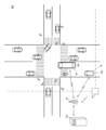
- FIG. 1 is a diagram showing the configuration of a traffic information distribution system according to an embodiment of the present disclosure.
- FIG. 2 is a diagram showing a configuration of a distribution server according to an embodiment of the present disclosure;
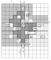
- FIG. 3 is a diagram for explaining travel information generated by the distribution server according to the embodiment of the present disclosure.
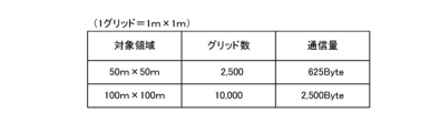
- FIG. 4 is a diagram for explaining the amount of communication when it is assumed that the distribution server according to the embodiment of the present disclosure transmits all of the travel information to the destination vehicle.
- FIG. 5 is a diagram for explaining the amount of communication when it is assumed that the distribution server according to the embodiment of the present disclosure transmits all of the travel information to the destination vehicle.
- FIG. 1 is a diagram showing the configuration of a traffic information distribution system according to an embodiment of the present disclosure.
- FIG. 2 is a diagram showing a configuration of a distribution server according to an embodiment of the present disclosure;
- FIG. 3 is a diagram for explaining travel information generated by the distribution server according to the embodiment of the present disclosure.
- FIG. 4 is
- FIG. 6 is a diagram for explaining an example of distribution information generated by a specifying unit in the distribution server according to the embodiment of the present disclosure
- FIG. 7 is a diagram illustrating an example format of a frame storing distribution information transmitted from the distribution server according to the embodiment of the present disclosure.
- FIG. 8 is a diagram for explaining Modification 1 of distribution information generated by the specifying unit in the distribution server according to the embodiment of the present disclosure.
- FIG. 9 is a diagram for explaining modification 2 of distribution information generated by the specifying unit in the distribution server according to the embodiment of the present disclosure.
- FIG. 10 is a diagram for explaining Modification 3 of distribution information generated by the specifying unit in the distribution server according to the embodiment of the present disclosure.
- FIG. 11 is a diagram for explaining modification 4 of distribution information generated by the specifying unit in the distribution server according to the embodiment of the present disclosure.
- FIG. 12 is an example of a sequence defining operation procedures of each device in the traffic information distribution system according to the embodiment of the present disclosure.
- FIG. 13 is a flow chart defining the operation procedure of the distribution server according to the embodiment of the present disclosure.
- the present disclosure has been made to solve the above-described problems, and aims to provide a traffic information distribution device, a traffic information distribution system, a traffic It is to provide an information distribution method and a traffic information distribution program.
- the specifying unit may be capable of specifying a priority area, which is an area that overlaps with an area satisfying a predetermined condition regarding the area, among the clear areas, and the transmitting unit receives position information of the priority area. You can send it to your vehicle.
- Areas that satisfy the predetermined conditions are areas of the road along the traveling direction of the vehicle, to which the location information of the priority area is transmitted, and objects traveling in a direction that intersects the road along the traveling direction. It may be an area where it is possible.
- the target area may include an intersection, and the area that satisfies the predetermined condition may be an area of the road corresponding to the light color of a traffic light device provided at the intersection.
- the dynamic information of the area of the road that can be traveled is selected while the traffic light device is lit in blue. It is possible to transmit dynamic information appropriately selected according to the light color.
- a traffic information distribution system acquires detection information indicating a detection result of an object in a target area from a detection device, and obtains from a blind spot area of the detection device in the target region a traffic information distribution device for transmitting position information of a clear area where no object exists to a vehicle in the target area based on the detection information; and the clear area mounted on the vehicle and transmitted from the traffic information distribution apparatus. and an in-vehicle device that assists the driving of the vehicle based on the position information of the vehicle.
- the information is useful for the vehicle, and It is possible to deliver dynamic information with a reduced amount of data. Therefore, it is possible to reduce the amount of communication when the dynamic information is distributed to the vehicle.
- a traffic information distribution method is a traffic information distribution method in a traffic information distribution device, comprising a step of acquiring detection information indicating a detection result of an object in a target area from a detection device; identifying a clear area in which no object exists, based on the acquired detection information, among the blind spot areas of the detection device in the target area; and transmitting position information of the identified clear area to the vehicle in the target area. and sending.
- the method of transmitting to the vehicle the position information of the clear area where it has been confirmed that there is no object among the areas recognized as blind spots by the traffic information distribution device is useful information for the vehicle, and It is possible to deliver dynamic information with a reduced amount of data. Therefore, it is possible to reduce the amount of communication when the dynamic information is distributed to the vehicle.
- a traffic information distribution program is a traffic information distribution program used in a traffic information distribution device, and causes a computer to transmit detection information indicating a detection result of an object in a target area from a detection device.
- an acquiring unit that acquires
- a specifying unit that specifies a clear area in which no object exists among blind spot areas of the detection device in the target area based on the detection information acquired by the acquiring unit
- the specifying unit A program for functioning as a transmission unit that transmits position information of the specified clear area to a vehicle in the target area.
- the information is useful for the vehicle, and It is possible to deliver dynamic information with a reduced amount of data. Therefore, it is possible to reduce the amount of communication when the dynamic information is distributed to the vehicle.
- FIG. 1 is a diagram showing the configuration of a traffic information distribution system according to an embodiment of the present disclosure.
- a traffic information distribution system 300 includes a distribution server (traffic information distribution device) 100, one or more in-vehicle devices 200, and one or more roadside units 60 installed on the roadside of a target area.
- a distribution server traffic information distribution device
- In-vehicle device 200 is mounted in vehicle 40 .
- the target area includes, for example, an intersection or a fork in the road.
- the roadside device 60 can communicate with the distribution server 100 via the radio base station 20, for example, using ITS (Intelligent Transport System) radio.
- ITS Intelligent Transport System
- the roadside device 60 periodically or irregularly detects surrounding objects using sensors such as cameras, LiDAR (Light Detection and Ranging), and millimeter wave radar devices, and transmits detection information indicating the detection results via the wireless base station 20. to the distribution server 100.
- Sensors such as cameras, LiDAR (Light Detection and Ranging), and millimeter wave radar devices, and transmits detection information indicating the detection results via the wireless base station 20. to the distribution server 100.
- Objects include vehicles and people.
- the detection information includes, for example, the type, position, speed and direction of movement of each detected object.
- the in-vehicle device 200 mounted on the vehicle 40 uses the sensors mounted on the vehicle 40 to periodically or irregularly monitor surrounding objects when the vehicle 40 is present in the target area, similarly to the roadside unit 60 . detect.
- the in-vehicle device 200 like the roadside device 60 , transmits detection information indicating the detection result to the distribution server 100 via the wireless base station 20 .
- each of the roadside device 60 and the in-vehicle device 200 is also referred to as a detection device.
- each detection device may be configured to transmit detection information indicating the detection result of an object to distribution server 100 via wireless base station 20 when receiving a request for detection information from distribution server 100 .
- the distribution server 100 receives detection information via the wireless base station 20 from each of one or more detection devices existing in the target area.
- Distribution server 100 generates driving information including dynamic information, that is, detection results of an object in a target area wider than the detection range of each detection device, based on the received one or more pieces of detection information.
- the travel information indicates the type, position, speed, direction of movement, etc. of each object present in the target area.
- the distribution server 100 transmits distribution information based on the generated travel information to the in-vehicle device 200 of the vehicle 40 existing in the target area via the wireless base station 20 .
- the vehicle 40 to which the distribution information is transmitted is also referred to as a distribution destination vehicle.
- the in-vehicle device 200 of the vehicle 40 which is the delivery destination vehicle, is, for example, the position of the vehicle 40 acquired by a GNNS (Global Navigation Satellite System) such as a GPS (Global Positioning System) receiver (not shown) mounted in the vehicle 40. Get information.
- the in-vehicle device 200 acquires the detection results of the surrounding objects detected using the sensors mounted on the vehicle 40 .
- the in-vehicle device 200 assists the driving of the vehicle 40 based on the acquired position information of the vehicle 40, the object detection result, the distribution information from the distribution server 100, and the like. Specifically, as driving assistance, the in-vehicle device 200 performs, for example, control to display the driving route on the screen of the car navigation system, and automatic driving by controlling the driving of the vehicle 40 such as speed. .
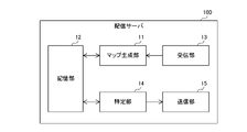
- FIG. 2 is a diagram showing a configuration of a distribution server according to an embodiment of the present disclosure
- distribution server 100 includes map generation unit 11 , storage unit 12 , reception unit (acquisition unit) 13 , identification unit 14 , and transmission unit 15 .
- One or both of the map generation unit 11 and the identification unit 14 are realized by, for example, a processing circuit (Circuitry) including one or more processors.
- the receiving unit 13 and the transmitting unit 15 are realized by a communication circuit such as a communication IC (Integrated Circuit).
- Storage unit 12 is, for example, a non-volatile memory.
- the storage unit 12 stores map data of a target area, which is static information.
- the reception unit 13 receives the detection information transmitted from the detection device via the wireless base station 20 and outputs the received detection information to the map generation unit 11 .
- the map generation unit 11 receives the detection information output from the reception unit 13 and generates driving information based on the detection information and the map data stored in the storage unit 12 .
- FIG. 3 is a diagram for explaining travel information generated by the distribution server according to the embodiment of the present disclosure.
- travel information generated based on detection information from the roadside device 60 will be described.
- the map generating unit 11 generates driving information indicating the state of each area when the target area is divided into grids, for example.
- Each region is hereinafter also referred to as a grid.
- the state of the grid includes, for example, an “unknown state” in which a detection result cannot be obtained because it is outside the detection range of the roadside unit 60 or no map data exists, and an “object present state” in which an object exists. , a “blind spot state” that is a blind spot for an object, and a “clear state” where no object exists.
- the area in the unknown state is also referred to as the "unknown area”
- the area in the presence of an object is also referred to as the "area with the object”
- the area in the blind spot state is also referred to as the "blind spot area”
- the area in the cleared state is also referred to as the "clear area”. called.
- unknown areas are not hatched
- object presence areas are hatched with oblique lines
- blind areas are hatched with lattices
- clear areas are hatched with dots. .
- map generation unit 11 generates four patterns of states of unknown state, object presence state, blind spot state and clear state, respectively, which are 2-bit data amounts of "00", " 01”, “02” and “03”.
- the target area is a range of 50 meters by 50 meters
- one grid in the driving information corresponds to a range of 2 meters by 2 meters.
- the target area is in the range of 100 meters by 100 meters and one grid in the driving information corresponds to the range of 2 meters by 2 meters
- the number of grids indicated by the driving information is 2500, and each grid The amount of data required to indicate the status is 625 bytes.
- the target area is a range of 50 meters by 50 meters, and one grid in the driving information corresponds to a range of 1 meter by 1 meter.
- the target area is in the range of 100 meters ⁇ 100 meters and one grid in the driving information corresponds to the range of 1 meter ⁇ 1 meter
- the number of grids indicated by the driving information is 10000
- the state of the grid The amount of data required to indicate is 2500 bytes.
- the distribution server 100 when all of the driving information indicating the state of each grid is transmitted to the destination vehicle, the amount of communication of the driving information increases. Therefore, as will be described later, the distribution server 100 generates distribution information with a smaller amount of communication than the driving information based on the driving information, and transmits the generated distribution information to the in-vehicle device 200 of the distribution destination vehicle.
- the identifying unit 14 identifies clear areas among the blind spot areas of the detecting device in the target area based on the detection information received by the receiving unit 13 .
- the identifying unit 14 generates driving information based on the detection information from the roadside unit 61, and identifies the blind area of the roadside unit 61 in the target area based on the generated driving information. Further, when receiving the detection information from the in-vehicle device 200, the specifying unit 14 updates the driving information based on the detection information, and based on the updated driving information, the area changed from the blind spot state to the clear state. identify.
- the identifying unit 14 generates distribution information including the position information of the identified clear area based on the updated travel information, and outputs the generated distribution information to the transmitting unit 15 .
- FIG. 6 is a diagram for explaining an example of distribution information generated by the specifying unit in the distribution server according to the embodiment of the present disclosure.
- map generator 11 generates driving information based on detection information from roadside unit 60 as shown in FIG. Assume that the detection information from each of the devices 200 a , 200 b , 200 c is received via the wireless base station 20 and the receiving section 13 .
- the map generation unit 11 determines that the state of the region R1, which is a part of the blind spot region shown in FIG. 3, is in the clear state, as shown in FIG. Assume that the driving information stored in the storage unit 12 is updated.
- the identification unit 14 refers to the driving information stored in the storage unit 12, and if there is an area changed from the blind spot state to the clear state before and after the driving information is updated, the area that is the clear area is identified here. R1 is identified, and distribution information including location information of the identified region R1 is generated. The identifying unit 14 then outputs the generated distribution information to the transmitting unit 15 .
- the transmission unit 15 receives the distribution information output from the identification unit 14 and transmits the distribution information to one or more distribution destination vehicles in the target area via the wireless base station 20 .
- the transmission unit 15 broadcasts a frame in which distribution information is stored to a plurality of vehicles 40 in the target area.
- FIG. 7 is a diagram showing an example format of a frame storing distribution information transmitted from the distribution server according to the embodiment of the present disclosure.
- the distribution information is stored in the data area of the frame, and includes, for example, provision point management number, provision point coordinate information, and state information.
- the provision point management number is, for example, a code of the prefecture that includes the target area, a provision point type code indicating whether the target area is an intersection or a parking/stop area, a unique provision point ID for each target area ( Identification).
- the provided point coordinate information includes, for example, the position information of the region R1 specified by the specifying unit 14, that is, the latitude and longitude of each grid included in the region R1.
- the state information indicates the state of each grid. That is, the state information indicates that all grids included in region R1 are in a clear state. Note that the distribution information does not have to include the state information.
- the in-vehicle device 200 When the in-vehicle device 200 receives the distribution information broadcast from the distribution server 100 via the wireless base station 20, for example, the in-vehicle device 200 checks the provision point ID and the like included in the frame in which the distribution information is stored, and obtains the contents of the distribution information. is used for driving assistance of the vehicle 40 or not.
- the in-vehicle device 200 uses the contents of the distribution information for driving assistance. decide. Then, the in-vehicle device 200 assists the driving of the vehicle 40 based on the position information of the region R1 indicated by the distribution information, the position information of the vehicle 40, and the like.
- the transmission unit 15 is not limited to the configuration of broadcasting the distribution information to a plurality of vehicles 40, and may be configured to unicast the distribution information to one or a plurality of vehicles 40 in the target area.
- the identifying unit 14 may be configured not to identify the blind area of the detection device in the target area.
- the specifying unit 14 assumes that the state of all grids in the target area is a blind spot state as an initial value, and based on the detection information from the detection device, the area that has changed from the blind spot state to the clear state identify.
- the specifying unit 14 may further specify the area that has changed from the clear state to the blind spot state. For example, when the identification unit 14 identifies both the area changed from the blind spot state to the clear state and the area changed from the clear state to the blind spot state before and after the driving information is updated, based on the driving information, Generate delivery information that includes location information for each of both identified areas.
- the distribution server 100 is not limited to the configuration of transmitting the distribution information including the position information of the region R1 that has changed from the blind spot state to the clear state.
- a configuration may be used in which the area is further specified and the distribution information including the position information of the specified priority area is transmitted.
- FIG. 8 is a diagram for explaining Modification 1 of distribution information generated by the specifying unit in the distribution server according to the embodiment of the present disclosure.
- the area that satisfies the predetermined condition is the intersection, and when the vehicle 40 turns right at the intersection, the oncoming straight vehicle travels until it reaches the intersection.
- the region of the lane As shown in FIG. 8, it is assumed that roads extend in four directions, north, south, east and west, centering on an intersection.
- the area that satisfies the predetermined condition includes the intersection and the driving lane of the vehicle 40 heading for the intersection among the four roads of north, south, east and west.
- the map generator 11 has generated driving information for a target area including an intersection, as shown in FIG. Also, as shown in FIG. 6, the map generation unit 11 determines that the state of the region R1, which is a part of the blind spot region shown in FIG. 3, is in the clear state based on the received detection information. In FIG. 8, the region R1 is hatched with vertical lines.
- the specifying unit 14 refers to the driving information stored in the storage unit 12, and as shown in FIG. Then, when the vehicle 40 makes a right turn at the intersection, a region R22 that overlaps with the region R21 of the traveling lane until the oncoming straight vehicle reaches the intersection is specified as a priority region.
- the region R21 is hatched with thick oblique lines, and the region R22 is filled.
- the identifying unit 14 generates distribution information including position information of the identified priority area based on the travel information, for example, and outputs the generated distribution information to the transmitting unit 15 .
- the transmission unit 15 broadcasts or broadcasts the distribution information received from the identification unit 14 to the in-vehicle device 200 of the destination vehicle via the wireless base station 20 in the same manner as in the case of transmitting the distribution information including the position information of the clear area described above. Unicast.
- FIG. 9 is a diagram for explaining modification 2 of distribution information generated by the specifying unit in the distribution server according to the embodiment of the present disclosure.
- the area satisfying the predetermined condition is the area of the road along the traveling direction of the delivery destination vehicle and the direction intersecting the road along the traveling direction. is the region in which the object can move.
- the map generator 11 has generated driving information for the target area as shown in FIG. Also, as shown in FIG. 6, the map generation unit 11 determines that the state of the region R1, which is a part of the blind spot region shown in FIG. 3, is in the clear state based on the received detection information. In FIG. 9, the region R1 is hatched with vertical lines.
- the specifying unit 14 refers to the travel information stored in the storage unit 12, and specifies, for example, a vehicle 40d approaching an intersection included in the target area as a delivery destination vehicle, as shown in FIG. .
- the identification unit 14 refers to the driving information, and, as shown in FIG. A region R32 that overlaps with a region R31, which is a region in which an object can move in a direction that intersects the road, such as a region of the road crossing the road and a crosswalk region that intersects the road, is specified as a priority region.
- the region R31 is hatched with thick oblique lines, and the region R32 is filled.
- the identifying unit 14 generates distribution information including position information of the identified priority area based on the travel information, for example, and outputs the generated distribution information to the transmitting unit 15 .
- the transmission unit 15 unicasts the distribution information received from the identification unit 14 to the in-vehicle device 200d of the vehicle 40d, which is the distribution destination vehicle, via the radio base station 20.
- the area that satisfies the predetermined condition is assumed to be a road area within a predetermined range from the center of the intersection.
- the map generator 11 has generated driving information for a target area including an intersection, as shown in FIG. Also, as shown in FIG. 6, the map generation unit 11 determines that the state of the region R1, which is a part of the blind spot region shown in FIG. 3, is in the clear state based on the received detection information. In FIG. 10, the region R1 is hatched with vertical lines.
- the specifying unit 14 refers to the driving information stored in the storage unit 12, and as shown in FIG. and a region R41 that is included within a predetermined range from the center of the intersection.
- the region R41 is hatched with thick oblique lines, and the region R42 is filled.
- the identifying unit 14 generates distribution information including position information of the identified priority area based on the travel information, for example, and outputs the generated distribution information to the transmitting unit 15 .
- the transmission unit 15 broadcasts or unicasts the distribution information received from the identification unit 14 to the in-vehicle device 200 of the distribution destination vehicle via the wireless base station 20 .
- FIG. 11 is a diagram for explaining modification 4 of distribution information generated by the specifying unit in the distribution server according to the embodiment of the present disclosure.
- the area satisfying the predetermined condition is assumed to be the area of the road corresponding to the light color of the signal lamp provided at the intersection.
- the map generator 11 has generated driving information for a target area including an intersection, as shown in FIG. Also, as shown in FIG. 6, the map generation unit 11 determines that the state of the region R1, which is a part of the blind spot region shown in FIG. 3, is in the clear state based on the received detection information. In FIG. 11, the region R1 is hatched with vertical lines.
- the receiving unit 13 transmits light color control information indicating the light color of the signal light device 30 from a signal controller (not shown) that controls the light color of the signal light device 30 provided at the intersection included in the target area to the wireless base station 20 . and outputs the received lamp color control information to the identification unit 14 .
- the signal light device 30a provided on the north side of the center of the intersection and the signal light device 30b provided on the south side of the center are lit in blue, and the signal light device 30c provided on the east side of the center and the intersection It is assumed that the signal lamp 30d provided on the west side of the center of the circle is lit in red.
- the identifying unit 14 changes from the blind spot state to the clear state before and after the driving information is updated, as shown in FIG.
- a road on which the vehicle can travel when the signal lamp 30 is lit in blue, that is, an area R52 overlapping the area R51 of the road along the north-south direction is specified as a priority area.
- the region R51 is hatched with thick oblique lines, and the region R52 is filled.
- the identifying unit 14 generates distribution information including position information of the identified priority area based on the travel information, for example, and outputs the generated distribution information to the transmitting unit 15 .
- the transmission unit 15 broadcasts or unicasts the distribution information received from the identification unit 14 to the in-vehicle device 200 of the distribution destination vehicle via the wireless base station 20 .
- the identifying unit 14 may identify the priority area by combining two or more of the above-described modified examples 1, 2, 3, and 4 methods.
- the specifying unit 14 may generate distribution information that includes both the position information of the area R1 that has changed from the blind spot state to the clear state and the position information of the priority area. However, in this case, the amount of communication of distribution information transmitted from distribution server 100 to vehicle 40 increases. For this reason, when the specifying unit 14 generates the distribution information including the position information of the priority area, it is preferable that the distribution information does not include the position information of the area R1.
- Each device in the traffic information distribution system 300 has a computer including a memory, and an arithmetic processing unit such as a CPU in the computer reads out from the memory a program including part or all of each step of the following flowcharts and sequences. Execute. Programs for these multiple devices can each be installed from the outside. Programs for these devices are distributed in a state of being stored in recording media or via communication lines.
- FIG. 12 is an example of a sequence defining operation procedures of each device in the traffic information distribution system according to the embodiment of the present disclosure.
- the roadside device 60 detects surrounding objects (step S10), and transmits detection information indicating the detection result to the distribution server 100 (step S11).
- the distribution server 100 receives the detection information transmitted from the roadside device 60, and based on the detection information, generates travel information indicating the detection result of the object in the target area (step S12).
- the distribution server 100 broadcasts a detection information request to, for example, the vehicles 40 existing in the target area.
- the in-vehicle devices 200a, 200b, and 200c respectively corresponding to the vehicles 40a, 40b, and 40c receive the request from the distribution server 100 (step S13).
- each of the in-vehicle devices 200a, 200b, and 200c detects surrounding objects (step S14), and transmits detection information indicating the detection results to the distribution server 100 (step S15).
- the distribution server 100 broadcasts the generated distribution information to, for example, one or more vehicles 40 in the target area.
- the in-vehicle device 200d of the vehicle 40d receives the distribution information (step S18).
- the in-vehicle device 200d detects surrounding objects (step S19).
- the in-vehicle device 200d confirms the provision point ID and the like included in the distribution information from the distribution server 100 and determines to use the content of the distribution information for driving support.
- the in-vehicle device 200d extracts, for example, position information of the clear area from the distribution information as information used for driving support (step S20).
- the in-vehicle device 200d determines whether or not the vehicle 40d can travel based on the result of object detection performed in step S19, the location information of the clear area extracted from the distribution information, and the location information of the vehicle 40d.
- the in-vehicle device 200d determines the area included in the flow line from the current position of the vehicle 40d to the right turn at the intersection, and the traveling lane of the oncoming straight vehicle heading for the intersection. When it is confirmed that all of the areas are cleared, it is determined that the vehicle 40d can turn right.
- the in-vehicle device 200d detects the area included in the flow line from the current position of the vehicle 40d to the right turn at the intersection, and the traveling lane of the oncoming straight vehicle heading for the intersection. is a blind spot area or an object presence area, it is determined that the vehicle 40d should not turn right (step S21).
- the in-vehicle device 200d supports the driving of the vehicle 40d according to the determination result of whether the vehicle 40d can travel.
- the in-vehicle device 200d determines that the vehicle 40d can turn right, it controls the running of the vehicle 40d so that the vehicle 40d turns right at the intersection.
- the in-vehicle device 200d determines that the vehicle 40d should not turn right, it controls the vehicle 40d to decelerate or stop the vehicle 40d (step S22).
- the in-vehicle device 200d may be configured to detect surrounding objects (step S19) before receiving distribution information from the distribution server 100.
- FIG. 13 is a flow chart defining the operation procedure of the distribution server according to the embodiment of the present disclosure.
- distribution server 100 as described in modification 1, modification 2, modification 3, and modification 4, is an area that satisfies a predetermined condition regarding the area, of area R1 that has changed from the blind spot state to the clear state.
- a case will be described where a certain priority area is specified and distribution information including position information of the specified priority area is transmitted.
- receiving unit 13 detects an object from at least one of one or more roadside units 60 and one or more vehicle-mounted devices 200 as detection devices. Information is received, and the received detection information is output to the map generator 11 (step S31).
- the map generation unit 11 Based on the detection information received from the reception unit 13 and the map data stored in the storage unit 12, the map generation unit 11 generates driving information indicating the detection result of the object in the target area.
- the obtained driving information is stored in the storage unit 12 . Note that, when the driving information is already stored in the storage unit 12, the map generating unit 11 updates the driving information stored in the storage unit 12 based on the newly received detection information (step S32). .
- the specifying unit 14 may compare the map data stored in the storage unit 12 with the driving information generated for the first time. For example, when the map data indicates a blind spot area that is a blind spot of an object that is a fixed object, the identifying unit 14 confirms whether or not there is an area that is in the blind spot state in the map data and in the clear state in the driving information. (step S33).
- the specifying unit 14 determines the priority area based on the latest travel information stored in the storage unit 12. Generates broadcast information that includes location information for Specifically, the identifying unit 14 generates distribution information including, for example, the latitude and longitude of each grid included in the priority area (step S35).
- the identification unit 14 outputs the generated distribution information to the transmission unit 15. Then, the transmission unit 15 transmits the distribution information received from the identification unit 14 to the in-vehicle device 200 of the distribution destination vehicle via the wireless base station 20 (step S36). Then, the operations after step S31 are performed again.
- distribution server 100 may be provided by cloud computing. That is, distribution server 100 according to the embodiment of the present disclosure may be configured by a plurality of cloud servers or the like.
- Each process (each function) of the above-described embodiments is implemented by a processing circuit including one or more processors.
- the processing circuit may be configured by an integrated circuit or the like in which one or more memories, various analog circuits, and various digital circuits are combined in addition to the one or more processors.
- the one or more memories store programs (instructions) that cause the one or more processors to execute the processes.
- the one or more processors may execute the above processes according to the program read from the one or more memories, or execute the above processes according to a logic circuit designed in advance to execute the above processes. may be executed.
- the processor is a CPU (Central Processing Unit), a GPU (Graphics Processing Unit), a DSP (Digital Signal Processor), an FPGA (Field Programmable Gate Array), and an ASIC (Application Specific Control Integrated Computer) compatible with various computers.
- processor Central Processing Unit
- GPU Graphics Processing Unit
- DSP Digital Signal Processor
- FPGA Field Programmable Gate Array
- ASIC Application Specific Control Integrated Computer
- the plurality of physically separated processors may cooperate with each other to execute the above processes.
- the processors installed in each of a plurality of physically separated computers cooperate with each other via networks such as LAN (Local Area Network), WAN (Wide Area Network), and the Internet to perform the above processes. may be executed.
- the program may be installed in the memory from an external server device or the like via the network, and may be CD-ROM (Compact Disc Read Only Memory), DVD-ROM (Digital Versatile Disk Read Only Memory), and semiconductor It may be distributed in a state stored in a recording medium such as a memory, and may be installed in the memory from the recording medium.
- CD-ROM Compact Disc Read Only Memory
- DVD-ROM Digital Versatile Disk Read Only Memory
- semiconductor It may be distributed in a state stored in a recording medium such as a memory, and may be installed in the memory from the recording medium.
- the acquisition unit periodically or irregularly acquires the detection information
- the specifying unit further specifies, based on the detection information acquired by the acquiring unit, an area in the target area that has changed from a clear state in which no object exists to a blind spot state that is a blind spot for an object,
- the traffic information distribution device wherein the transmission unit transmits to the vehicle the position information of the area identified by the identification unit that has changed from the clear state to the blind spot state.
- Detection information indicating the detection result of an object in a target area is obtained from a detection device, and position information of a clear area in which no object exists is obtained based on the obtained detection information among the blind spot areas of the detection device in the target area.
- a traffic information distribution device for transmitting to vehicles in the target area; an in-vehicle device that is mounted on the vehicle and performs driving assistance of the vehicle based on the position information of the clear area transmitted from the traffic information distribution device; The in-vehicle device detects surrounding objects, and based on at least one of object detection results, location information of the clear area received from the traffic information distribution device, and location information of the vehicle, A traffic information distribution system that determines whether or not the vehicle can travel, and supports driving of the vehicle according to the determination result of whether or not the vehicle can travel.
- a traffic information distribution device with a processing circuit, The processing circuit is Acquire detection information indicating the detection result of the object in the target area from the detection device, Identifying a clear area where no object exists, based on the acquired detection information, among the blind spot areas of the detection device in the target area; A traffic information distribution device for transmitting position information of the identified clear area to vehicles in the target area.
Landscapes
- Engineering & Computer Science (AREA)
- Computer Networks & Wireless Communication (AREA)
- Signal Processing (AREA)
- Physics & Mathematics (AREA)
- General Physics & Mathematics (AREA)
- Traffic Control Systems (AREA)
Priority Applications (1)
| Application Number | Priority Date | Filing Date | Title |
|---|---|---|---|
| JP2023542257A JP7803345B2 (ja) | 2021-08-18 | 2022-07-07 | 交通情報配信装置、交通情報配信システム、交通情報配信方法および交通情報配信プログラム |
Applications Claiming Priority (2)
| Application Number | Priority Date | Filing Date | Title |
|---|---|---|---|
| JP2021133049 | 2021-08-18 | ||
| JP2021-133049 | 2021-08-18 |
Publications (1)
| Publication Number | Publication Date |
|---|---|
| WO2023021875A1 true WO2023021875A1 (ja) | 2023-02-23 |
Family
ID=85240544
Family Applications (1)
| Application Number | Title | Priority Date | Filing Date |
|---|---|---|---|
| PCT/JP2022/026947 Ceased WO2023021875A1 (ja) | 2021-08-18 | 2022-07-07 | 交通情報配信装置、交通情報配信システム、交通情報配信方法および交通情報配信プログラム |
Country Status (2)
| Country | Link |
|---|---|
| JP (1) | JP7803345B2 (https=) |
| WO (1) | WO2023021875A1 (https=) |
Cited By (1)
| Publication number | Priority date | Publication date | Assignee | Title |
|---|---|---|---|---|
| WO2025022861A1 (ja) * | 2023-07-26 | 2025-01-30 | 日産自動車株式会社 | 物体検出方法及び物体検出システム |
Citations (1)
| Publication number | Priority date | Publication date | Assignee | Title |
|---|---|---|---|---|
| JP2018026009A (ja) * | 2016-08-10 | 2018-02-15 | パナソニック インテレクチュアル プロパティ コーポレーション オブ アメリカPanasonic Intellectual Property Corporation of America | 動的地図構成方法、動的地図構成システム及び移動端末 |
Family Cites Families (1)
| Publication number | Priority date | Publication date | Assignee | Title |
|---|---|---|---|---|
| CN114127821A (zh) * | 2019-07-12 | 2022-03-01 | 日产自动车株式会社 | 信息处理装置、信息处理方法以及程序 |
-
2022
- 2022-07-07 JP JP2023542257A patent/JP7803345B2/ja active Active
- 2022-07-07 WO PCT/JP2022/026947 patent/WO2023021875A1/ja not_active Ceased
Patent Citations (1)
| Publication number | Priority date | Publication date | Assignee | Title |
|---|---|---|---|---|
| JP2018026009A (ja) * | 2016-08-10 | 2018-02-15 | パナソニック インテレクチュアル プロパティ コーポレーション オブ アメリカPanasonic Intellectual Property Corporation of America | 動的地図構成方法、動的地図構成システム及び移動端末 |
Cited By (1)
| Publication number | Priority date | Publication date | Assignee | Title |
|---|---|---|---|---|
| WO2025022861A1 (ja) * | 2023-07-26 | 2025-01-30 | 日産自動車株式会社 | 物体検出方法及び物体検出システム |
Also Published As
| Publication number | Publication date |
|---|---|
| JP7803345B2 (ja) | 2026-01-21 |
| JPWO2023021875A1 (https=) | 2023-02-23 |
Similar Documents
| Publication | Publication Date | Title |
|---|---|---|
| US11846522B2 (en) | Warning polygons for weather from vehicle sensor data | |
| JP7156206B2 (ja) | 地図システム、車両側装置、およびプログラム | |
| JP7147712B2 (ja) | 車両側装置、方法および記憶媒体 | |
| JP6844642B2 (ja) | 協働知覚のためのマルチレベルハイブリッドv2x通信 | |
| CN108780604B (zh) | 用于车辆的自动化车道指配 | |
| JP6303564B2 (ja) | 位置情報校正装置、位置情報校正アプリケーションプログラム | |
| CN111693055B (zh) | 道路网络变化检测和所检测的变化的本地传播 | |
| WO2020045317A1 (ja) | 地図システム、方法および記憶媒体 | |
| US10917808B2 (en) | Extra-vehicular communication device, onboard device, onboard communication system, communication control method, and communication control program | |
| JP2018182661A (ja) | 通信システム、車両搭載器及びプログラム | |
| JP2019519048A (ja) | 動的車線画定 | |
| CN107407730A (zh) | 自主车辆的实时占用地图创建系统 | |
| US11227420B2 (en) | Hazard warning polygons constrained based on end-use device | |
| JP2018101384A (ja) | 車車間通信システム、路側通信装置、車載通信装置及び車車間通信方法 | |
| WO2011142226A1 (ja) | 通信装置、車両間通信制御方法及び車両間通信システム | |
| WO2020045322A1 (ja) | 地図システム、車両側装置、方法および記憶媒体 | |
| JP7729111B2 (ja) | 交通情報提供装置、交通情報配信装置、交通情報提供方法、交通情報配信方法、交通情報提供プログラムおよび交通情報配信プログラム | |
| US20210348944A1 (en) | Vehicle, apparatus, method, and computer program for determining a merged environmental map | |
| JP7803345B2 (ja) | 交通情報配信装置、交通情報配信システム、交通情報配信方法および交通情報配信プログラム | |
| US11217090B2 (en) | Learned intersection map from long term sensor data | |
| US12601605B2 (en) | Electronic horizon for ADAS function | |
| US10621864B1 (en) | V2X vehicle pullout advisory system | |
| CN114449481B (zh) | 基于v2x技术确定所在车道当前信号灯灯色的方法及系统 | |
| US20250085418A1 (en) | Vehicle position estimating device, vehicle position estimating system, and vehicle position estimating method | |
| JP2004317386A (ja) | ナビゲーション装置および道路情報配信システム |
Legal Events
| Date | Code | Title | Description |
|---|---|---|---|
| 121 | Ep: the epo has been informed by wipo that ep was designated in this application |
Ref document number: 22858198 Country of ref document: EP Kind code of ref document: A1 |
|
| WWE | Wipo information: entry into national phase |
Ref document number: 2023542257 Country of ref document: JP |
|
| NENP | Non-entry into the national phase |
Ref country code: DE |
|
| 122 | Ep: pct application non-entry in european phase |
Ref document number: 22858198 Country of ref document: EP Kind code of ref document: A1 |