WO2023021765A1 - 画像処理装置、および画像処理方法ならびにプログラム - Google Patents
画像処理装置、および画像処理方法ならびにプログラム Download PDFInfo
- Publication number
- WO2023021765A1 WO2023021765A1 PCT/JP2022/011861 JP2022011861W WO2023021765A1 WO 2023021765 A1 WO2023021765 A1 WO 2023021765A1 JP 2022011861 W JP2022011861 W JP 2022011861W WO 2023021765 A1 WO2023021765 A1 WO 2023021765A1
- Authority
- WO
- WIPO (PCT)
- Prior art keywords
- image
- water
- laser beam
- depth
- image sensor
- Prior art date
- Legal status (The legal status is an assumption and is not a legal conclusion. Google has not performed a legal analysis and makes no representation as to the accuracy of the status listed.)
- Ceased
Links
Images


Classifications
-
- G—PHYSICS
- G06—COMPUTING OR CALCULATING; COUNTING
- G06T—IMAGE DATA PROCESSING OR GENERATION, IN GENERAL
- G06T5/00—Image enhancement or restoration
- G06T5/80—Geometric correction
-
- G—PHYSICS
- G06—COMPUTING OR CALCULATING; COUNTING
- G06T—IMAGE DATA PROCESSING OR GENERATION, IN GENERAL
- G06T7/00—Image analysis
- G06T7/50—Depth or shape recovery
- G06T7/521—Depth or shape recovery from laser ranging, e.g. using interferometry; from the projection of structured light
-
- G—PHYSICS
- G01—MEASURING; TESTING
- G01B—MEASURING LENGTH, THICKNESS OR SIMILAR LINEAR DIMENSIONS; MEASURING ANGLES; MEASURING AREAS; MEASURING IRREGULARITIES OF SURFACES OR CONTOURS
- G01B11/00—Measuring arrangements characterised by the use of optical techniques
-
- G—PHYSICS
- G01—MEASURING; TESTING
- G01B—MEASURING LENGTH, THICKNESS OR SIMILAR LINEAR DIMENSIONS; MEASURING ANGLES; MEASURING AREAS; MEASURING IRREGULARITIES OF SURFACES OR CONTOURS
- G01B11/00—Measuring arrangements characterised by the use of optical techniques
- G01B11/24—Measuring arrangements characterised by the use of optical techniques for measuring contours or curvatures
- G01B11/245—Measuring arrangements characterised by the use of optical techniques for measuring contours or curvatures using a plurality of fixed, simultaneously operating transducers
-
- G—PHYSICS
- G06—COMPUTING OR CALCULATING; COUNTING
- G06T—IMAGE DATA PROCESSING OR GENERATION, IN GENERAL
- G06T5/00—Image enhancement or restoration
- G06T5/50—Image enhancement or restoration using two or more images, e.g. averaging or subtraction
-
- G—PHYSICS
- G06—COMPUTING OR CALCULATING; COUNTING
- G06T—IMAGE DATA PROCESSING OR GENERATION, IN GENERAL
- G06T7/00—Image analysis
- G06T7/50—Depth or shape recovery
- G06T7/55—Depth or shape recovery from multiple images
- G06T7/593—Depth or shape recovery from multiple images from stereo images
-
- G—PHYSICS
- G06—COMPUTING OR CALCULATING; COUNTING
- G06T—IMAGE DATA PROCESSING OR GENERATION, IN GENERAL
- G06T7/00—Image analysis
- G06T7/80—Analysis of captured images to determine intrinsic or extrinsic camera parameters, i.e. camera calibration
- G06T7/85—Stereo camera calibration
-
- G—PHYSICS
- G06—COMPUTING OR CALCULATING; COUNTING
- G06T—IMAGE DATA PROCESSING OR GENERATION, IN GENERAL
- G06T2207/00—Indexing scheme for image analysis or image enhancement
- G06T2207/10—Image acquisition modality
- G06T2207/10028—Range image; Depth image; 3D point clouds
-
- Y—GENERAL TAGGING OF NEW TECHNOLOGICAL DEVELOPMENTS; GENERAL TAGGING OF CROSS-SECTIONAL TECHNOLOGIES SPANNING OVER SEVERAL SECTIONS OF THE IPC; TECHNICAL SUBJECTS COVERED BY FORMER USPC CROSS-REFERENCE ART COLLECTIONS [XRACs] AND DIGESTS
- Y02—TECHNOLOGIES OR APPLICATIONS FOR MITIGATION OR ADAPTATION AGAINST CLIMATE CHANGE
- Y02A—TECHNOLOGIES FOR ADAPTATION TO CLIMATE CHANGE
- Y02A90/00—Technologies having an indirect contribution to adaptation to climate change
- Y02A90/30—Assessment of water resources
Definitions
- the present disclosure relates to an image processing device and an image processing method.
- Patent Document 1 proposes a method of calibrating a captured image using correction data acquired in advance.
- An image processing apparatus includes an image sensor that captures an image of a measurement object in water, a first laser light source that emits a first laser beam in water, and a first laser light source in water.
- a second laser light source that emits a second laser beam from a position different from the first laser beam obtained by imaging the first laser beam and the second laser beam with an image sensor at a first water depth information and second information obtained by imaging the first laser light and the second laser light with the image sensor at the second water depth, which is the water depth at which the image sensor captures an image of the measurement target.
- a correction data generation unit for generating correction data used for correcting distortion of an image captured by the image sensor at the second water depth based on the first water depth;
- An image processing method includes capturing an image of a measurement object in water with an image sensor, emitting a first laser beam in water, and emitting a first laser light source in water.
- the second information is obtained.
- a program emits a first laser beam in water, emits a second laser beam in water from a position different from that of a first laser light source,
- a first laser beam and a second laser beam acquired by an image sensor at a first water depth 1 information, and second information acquired by imaging the first laser light and the second laser light with the image sensor at the second water depth, which is the water depth at which the image sensor captures the image of the measurement target. and the correction data used to correct the distortion of the image captured by the image sensor at the second water depth is generated.
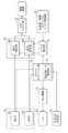
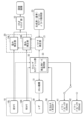
- FIG. 1 is a block diagram schematically showing one configuration example of an image processing apparatus according to a first embodiment of the present disclosure
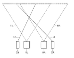
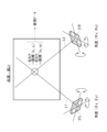
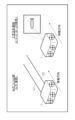
- FIG. FIG. 3 is an explanatory diagram showing an example of an irradiation state of two line laser beams by a laser and a viewing range by a stereo camera
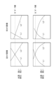
- It is explanatory drawing which shows an example of the captured image of two line laser beams by a stereo camera.
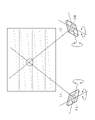
- FIG. 4 is an explanatory diagram showing an example of scanning of two line laser beams by a scanning mechanism
- FIG. 5 is an explanatory diagram showing an example of an intersection of two line laser beams when the water depth is shallow;
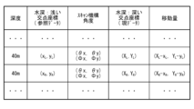
- FIG. 10 is an explanatory diagram showing an example of an intersection of two line laser beams when the water depth is deep; 4 is an explanatory diagram showing an example of information held in a correction data holding unit in the image processing apparatus according to the first embodiment;
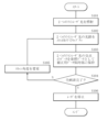
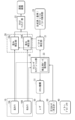
- FIG. 7 is a flowchart showing an example of reference data creation processing performed when the water depth is shallow in the image processing apparatus according to the first embodiment; 7 is a flowchart showing an example of calibration processing performed when the water depth is deep in the image processing apparatus according to the first embodiment;
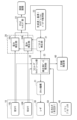
- FIG. 11 is a block diagram schematically showing a configuration example of an image processing apparatus according to a second embodiment;
- FIG. FIG. 10 is a configuration diagram schematically showing one configuration example of an autonomous underwater robot to which an image processing device according to a second embodiment is applied;
- FIG. 11 is a block diagram schematically showing one configuration example of an image processing apparatus according to a third embodiment
- FIG. 11 is an explanatory diagram showing an example of information held in a correction data holding unit in an image processing apparatus according to a fourth embodiment
- FIG. FIG. 12 is a block diagram schematically showing one configuration example of an image processing apparatus according to a fifth embodiment
- FIG. 11 is a configuration diagram schematically showing one configuration example of an autonomous underwater robot to which an image processing device according to a fifth embodiment is applied
- FIG. 14 is a flowchart showing an example of processing for generating a depth image in the image processing device according to the fifth embodiment
- Patent Document 1 Japanese Patent Application Laid-Open No. 2011-248414 describes a method of acquiring correction data for each pressure resistance as an image processing system that enables obtaining an image equivalent to an image captured under a normal pressure environment. Proposed. However, since calibration is performed in advance, the causal relationship between the assumed withstand voltage and the actually occurring withstand voltage may not be correct. In the technique proposed in Patent Document 1, the correction information for each pressure is acquired in advance and the difference parameter (movement vector) from the normal pressure environment is calculated. Correct 3D measurement may not be possible because it depends on the accuracy of the temperature sensor and the mechanical shape change that occurs when actually submerged in a high-pressure environment does not always match the acquired parameters.
- FIG. 1 schematically shows a configuration example of an image processing apparatus according to the first embodiment of the present disclosure.
- the image processing device is mounted, for example, on an autonomous underwater robot and used for three-dimensional measurement underwater such as in the sea.
- the image processing apparatus includes a stereo camera 10, a distortion correction section 20, a parameter correction section 21, a stereo matching section 22, and a generated calibration parameter holding section 23.
- the image processing apparatus according to the first embodiment further includes a laser 30 , a scanning mechanism 31 , a line laser calibration section 32 and a pressure sensor 50 .
- the stereo matching unit 22 corresponds to a specific example of the "depth image generation unit” in the technology of the present disclosure.
- the line laser calibration unit 32 corresponds to a specific example of the “correction data generation unit” in the technique of the present disclosure.
- the distortion correction unit 20, the parameter correction unit 21, the stereo matching unit 22, and the line laser calibration unit 32 include, for example, one or more CPUs (Central Processing Units), one or more ROMs (Read Only Memory), and one Alternatively, it may be configured by a computer equipped with multiple RAMs (Random Access Memories). In this case, the processing of each unit by the distortion correction unit 20, the parameter correction unit 21, the stereo matching unit 22, and the line laser calibration unit 32 is one or more processes based on programs stored in one or more ROMs or RAMs.
- each unit by the distortion correcting unit 20, the parameter correcting unit 21, the stereo matching unit 22, and the line laser calibration unit 32 may be one or more processes based on a program externally supplied via a wired or wireless network, for example. may be realized by executing the CPU.
- FIG. 2 shows an example of the irradiation state of the two line laser beams L1 and L2 by the laser 30 and the viewing range of the stereo camera 10.
- the stereo camera 10 is an image sensor that captures an image of an object to be measured underwater.
- the stereo camera 10 has a left camera 10L and a right camera 10R, as shown in FIG.
- FIG. 2 shows an example of the visual field range 11L of the left camera 10L and the visual field range 11R of the right camera 10R.
- the generated calibration parameter holding unit 23 holds generated calibration parameters that are generated in advance on land, for example, and serve as a reference for calibration.
- the parameter correction unit 21 uses calibration parameters (generated calibration parameters).
- the distortion correction section 20 has a distortion correction section 20L for the left camera and a distortion correction section 20R for the right camera.
- the distortion corrector 20 corrects the distortion of the captured image of the measurement object captured by the stereo camera 10 based on the corrected calibration parameters corrected by the parameter corrector 21 .
- the stereo matching unit 22 is a depth image generation unit that generates a depth image based on the captured image of the measurement object corrected by the distortion correction unit 20.
- the stereo matching unit 22 stereo-matches the image captured by the left camera 10L after distortion correction by the distortion correction unit 20L and the image captured by the right camera 10R after distortion correction by the distortion correction unit 20R. Processing is performed to generate a depth image containing 3D measurement information.
- the laser 30 has a left laser 30L and a right laser 30R, as shown in FIG.
- the left laser 30L is a first laser light source that emits a line laser beam L1 as a first laser beam underwater.
- the right laser 30R is a second laser light source that emits line laser light L2 as a second laser light from a position in water different from that of the left laser 30L.
- FIG. 2 shows an example of the optical path of the line laser beam L1 emitted from the left laser 30L and the optical path of the line laser beam L2 emitted from the right laser 30R.
- the left laser 30L is arranged, for example, on the left side of the left camera 10L.
- the right laser 30R is arranged, for example, on the right side of the right camera 10R.
- the number of lasers 30 is not limited to two.
- two lasers may be installed in the vertical direction.
- the scanning mechanism 31 has a left scanning mirror 31L and a right scanning mirror 31R, as shown in FIGS. 4 to 6, which will be described later.
- the left scanning mirror 31L is a first scanning mechanism that scans the line laser beam L1 emitted from the left laser 30L.
- the right scanning mirror 31R is a second scanning mechanism that scans the line laser beam L2 emitted from the right laser 30R.
- the left scan mirror 31L and the right scan mirror 31R may each be, for example, a MEMS (Micro Electro Mechanical Systems) mirror.
- the line laser calibration unit 32 has a correction data holding unit 33. Note that the correction data holding unit 33 may be provided outside the line laser calibration unit 32 .
- the line laser calibration unit 32 acquires information on the intersection of the two line laser beams L1 and L2 for all pixels of the stereo camera 10 by controlling the scanning of the two line laser beams L1 and L2 by the scanning mechanism 31 .
- the line laser calibration unit 32 holds, as reference data in advance, information on the intersection of the two line laser beams L1 and L2 visible from the stereo camera 10 at a shallow water depth (first water depth).
- the amount of distortion of the image captured by the stereo camera 10 is calculated by comparing with the information, and the distortion of the image is corrected.
- the line laser calibration unit 32 obtains first information obtained by imaging the line laser light L1 and the line laser light L2 with the stereo camera 10 at a first water depth (shallow water depth), and the measurement target with the stereo camera 10. Based on the second information obtained by imaging the line laser light L1 and the line laser light L2 with the stereo camera 10 at a second water depth (deep water depth) that is the water depth at which an object is imaged, the second correction data (correction parameters) used to correct the distortion of the image captured by the stereo camera 10 at a water depth of .
- the line laser calibration unit 32 acquires, as first information, information on a first intersection point between the line laser beam L1 and the line laser beam L2 captured by the stereo camera 10 at the first water depth, and obtains second information.
- Information on a second intersection point corresponding to the first intersection point of the line laser light L1 and the line laser light L2 captured by the stereo camera 10 at the depth of water is acquired as second information, and on the image captured by the stereo camera 10, Correction data (correction parameter) is generated based on the information about the amount of movement between the first intersection and the second intersection.
- the line laser calibration unit 32 aligns the left scan mirror 31L and the right scan mirror 31R so that information on the first intersection point and information on the second intersection point can be obtained for all pixels on the image captured by the stereo camera 10. Scan control.
- the correction data holding unit 33 converts the information of the first intersection point and the information of the second intersection point into the information of the first scan angle by the left scan mirror 31L and the second scan angle by the right scan mirror 31R. information in connection with
- the pressure sensor 50 is a water pressure gauge that measures the pressure in water, and can estimate the depth.
- FIG. 3 shows an example of an image captured by the stereo camera 10 of the two line laser beams L1 and L2.
- the intersection of the two line laser beams L1 and L2 is on the epipolar line because the water depth is shallow, that is, the calibration parameters match the reference generated calibration parameters. Therefore, distortion correction by the distortion correction unit 20 can be performed correctly.
- the lower part of FIG. 3 shows a case where the water depth is deep, and the image is distorted due to the influence of the high withstand voltage on the equipment in which the image processing device is mounted. In this case, the intersection of the two line laser beams L1 and L2 is not on the epipolar line. Therefore, if the generated reference calibration parameters are used as they are, the distortion correction unit 20 cannot create a correct corrected image, and the distance image (depth image) calculated by the stereo matching unit 22 cannot obtain a correct result. .
- FIG. 4 shows an example of scanning by the scanning mechanism 31 with two line laser beams L1 and L2.
- FIG. 4 shows an example in which the scanning mechanism 31 is used to scan the two line laser beams L1 and L2 so that the intersection of the two line laser beams L1 and L2 can be photographed with all the pixels of the left camera 10L.
- the example of FIG. 4 shows scanning with the left line laser beam L1.
- the scan angles of all pixel positions are stored in the correction data holding unit 33, and when the water depth changes (second water depth), the intersection point at the same scan angle is stored. By comparing with the pixel position, the amount of movement of the intersection due to water depth can be obtained.
- FIG. 5 shows an example of the intersection of the two line laser beams L1 and L2 when the water depth is shallow (first water depth).
- FIG. 6 shows an example of intersections of two line laser beams L1 and L2 when the water depth is deep (second water depth).
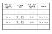
- FIG. 7 shows an example of information held in the correction data holding unit 33. As shown in FIG.
- L1 and L2 has coordinates (X L , Y L ) on the image captured by the left camera 10L and coordinates (X R , Y R ) on the image captured by the right camera 10R.
- the movement amount (X L ⁇ x L , Y L ⁇ y L ) for the left camera 10L and the movement amount (X R ⁇ x R , Y R ⁇ y R ) and the coordinates of all pixels on the captured image of the stereo camera 10 are visually observed, and the obtained information (FIG. 7) is used as correction data (correction parameter ) in the correction data holding unit 33 .
- the line laser calibration unit 32 when performing calibration according to the withstand voltage, the line laser calibration unit 32 outputs two line laser beams L1 and L2 while controlling the scanning mechanism 31, Line laser calibration is performed using captured images obtained from the stereo camera 10, and correction parameters are obtained by the above method.
- the parameter correcting unit 21 and the distortion correcting unit 20 use the captured image obtained from the stereo camera 10, the generated calibration parameters that are generated in advance as a reference for calibration, and the correction parameters from the stereo camera 10.
- a distortion correction is performed on the obtained captured image.
- the stereo matching unit 22 performs stereo matching from the distortion-corrected captured image to generate a depth image.
- Line laser calibration may not be performed for each frame of imaging by the stereo camera 10, but may be performed periodically when water pressure fluctuates or a device such as a robot equipped with an image processing device descends.
- FIG. 8 is a flowchart showing an example of reference data creation processing performed when the water depth is shallow in the image processing apparatus according to the first embodiment.
- step S101 two line laser beams L1 and L2 are emitted by the laser 30 and the scanning mechanism 31 (step S101).
- step S102 the optical paths of the two line laser beams L1 and L2 are captured by the stereo camera 10 (step S102).
- step S103 the line laser calibration unit 32 holds the data of the intersection of the two line laser beams L1 and L2 as reference data in the correction data holding unit 33 (step S103).
- the line laser calibration unit 32 determines whether or not scanning has been completed for all pixels of the stereo camera 10 (step S104). If it is determined that the scanning of all pixels has not been completed (step S104; N), the line laser calibration unit 32 next changes the scanning angle of the scanning mechanism 31 (step S105), and the process of step S102 is performed. back to
- step S104 when it is determined that scanning for all pixels has been completed (step S104; Y), the line laser calibration section 32 stops the laser 30 (step S106).
- FIG. 9 is a flowchart showing an example of calibration processing performed when the water depth is deep in the image processing apparatus according to the first embodiment.
- two line laser beams L1 and L2 are emitted by the laser 30 and the scanning mechanism 31 (step S201).
- the optical paths of the two line laser beams L1 and L2 are captured by the stereo camera 10 (step S202).
- the line laser calibration unit 32 holds the data of the intersection of the two line laser beams L1 and L2 as current data in the correction data holding unit 33 (step S203).
- the line laser calibration unit 32 determines whether or not scanning has been completed for all pixels of the stereo camera 10 (step S204). If it is determined that the scanning of all pixels has not been completed (step S204; N), the line laser calibration unit 32 next changes the scanning angle of the scanning mechanism 31 (step S205), and the process of step S202 is performed. back to
- the line laser calibration unit 32 stops the laser 30 (step S206).
- the line laser calibration unit 32 generates correction parameters from the reference data and current data held in the correction data holding unit 33 (step S207).
- a captured image of the object to be measured is captured by the stereo camera 10 (step S208).
- the parameter correction unit 21 uses the correction parameters to correct the generated calibration parameters (step S209).
- the distortion correction unit 20 uses the corrected calibration parameters to correct the distortion of the image captured by the stereo camera 10 (stereo camera image) (step S210).
- the stereo matching unit 22 generates depth images from the distortion-corrected stereo images (step S211).
- the line laser calibration unit 32 determines whether the depth has changed based on the information from the pressure sensor 50 (step S212). When the line laser calibration unit 32 determines that the depth has not changed (step S212; N), the process returns to step S208. On the other hand, when the line laser calibration unit 32 determines that the depth has changed (step S212; Y), the process returns to step S201.
- changes in the distortion of the captured image are measured in real time and fed back to the distortion correction unit 20, so three-dimensional measurement can always be performed with correctly corrected images. At that time, it is possible to easily calibrate the captured image at the place where the three-dimensional measurement is performed. Even if the distortion that actually occurs is different from the pre-measurement, calibration can be performed on the spot (real time), so correct correction is possible.
- the image processing apparatus it is possible to calibrate a captured image based on actual data even under a plurality of pressure resistances.
- a correct depth image can be calculated by stereo matching.
- FIG. 10 schematically shows a configuration example of an image processing apparatus according to the second embodiment.
- FIG. 11 schematically shows a configuration example of the autonomous underwater robot 1 to which the image processing device according to the second embodiment is applied.
- the image processing apparatus according to the second embodiment has a configuration in which a pattern projector 40 is added to the configuration of the image processing apparatus according to the first embodiment (FIG. 1).
- the pattern projector 40 irradiates the measurement object with a predetermined pattern (right side of FIG. 11). As a result, even if the object to be measured has no texture and is not suitable for stereo matching, it is possible to perform correct three-dimensional measurement by projecting a texture suitable for stereo matching. As shown on the left side of FIG. 11, when performing calibration, the laser 30 is used as in the image processing apparatus according to the first embodiment.
- FIG. 12 schematically shows a configuration example of an image processing apparatus according to the third embodiment.
- the image processing apparatus has a configuration in which two pattern projectors 41 and 42 are added to the configuration of the image processing apparatus according to the first embodiment (FIG. 1). there is
- the two pattern projectors 41 and 42 can irradiate predetermined patterns with different wavelength bands onto the measurement object.
- the pattern projector 41 may be capable of emitting a predetermined pattern in the 530 nm band.
- the pattern projector 42 may be able to irradiate a predetermined pattern in the 850 nm band.
- a configuration may be employed in which three or more pattern projectors are provided and three or more predetermined patterns with different wavelength bands can be emitted.
- the line laser calibration unit 32 estimates the turbidity of the water based on the captured images of the line laser light L1 and the line laser light L2 by the stereo camera 10 in a pressure-resistant state (second water depth), and estimates the water turbidity , one of the two pattern projectors 41 and 42 is selected as a pattern projector for irradiating a predetermined pattern.
- the closer the wavelength of light is to blue (440 nm band), the lower the absorptivity in water, and the longer the reach of light. utilizes the fact that the amount of backscattered light differs depending on the wavelength of light (near-infrared band is less than visible band).
- the line laser calibration unit 32 estimates the light reaching distance when the two line laser beams L1 and L2 are irradiated from the image captured by the stereo camera 10, and also estimates the turbidity in the water.
- the pattern projector 41 for the 530 nm band has little absorption in water, and when the turbidity is high, the 850 nm band pattern projector 42 has little backscattered light because the 530 nm band has a lot of backscattered light and the pattern becomes unclear. By switching and using, highly robust three-dimensional measurement becomes possible.
- FIG. 13 shows an example of information held in the correction data holding unit 33 in the image processing apparatus according to the fourth embodiment.
- the basic configuration of the image processing device according to the fourth embodiment may be substantially the same as the configuration (FIG. 12) of the image processing device according to the third embodiment.
- the image processing apparatus according to the fourth embodiment as shown in FIG. 13, as information held by the correction data holding unit 33, in addition to the information shown in FIG. 7, depth (water depth) information hold.
- the correction data holding unit 33 holds the correction data (correction parameter) generated by the line laser calibration unit 32 in association with the depth information of the second water depth (deep water depth).
- the correction data holding unit 33 holds the correction parameters together with the depth information estimated from the pressure sensor 50 .
- the distortion of the captured image may be corrected based on the correction parameters already held in the correction data holding unit 33 .
- FIG. 14 schematically shows a configuration example of an image processing apparatus according to the fifth embodiment.
- FIG. 15 schematically shows a configuration example of the autonomous underwater robot 1 to which the image processing device according to the fifth embodiment is applied.
- the image processing apparatus has a pattern projector 40 and a Z distance estimation unit 60 added to the configuration of the image processing apparatus according to the first embodiment (FIG. 1). It is configured.
- the Z distance estimating unit 60 estimates the distance Z to the measurement object based on the captured images of the line laser light L1 and the line laser light L2 captured by the stereo camera 10 in a pressure-resistant state (second water depth). Based on the distance Z estimated by the Z distance estimating unit 60, the stereo matching unit 22 sets the search range of the measurement object for generating the depth image.
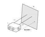
- the image processing apparatus is suitable for distance measurement of planar objects such as dam walls 70, as shown in FIG.
- triangulation is performed based on a plurality of points irradiated with the two line laser beams L1 and L2 irradiated on the wall 70.
- the range that can be measured is limited due to limited memory resources and speeding up. Therefore, by using the estimated distance to the wall 70 to further limit the search range of the stereo matching unit 22, it is possible to further reduce resources and increase the speed.
- an advantage of limiting the search range by the stereo matching unit 22 an improvement in robustness such as prevention of distance estimation errors due to false matching can be expected.
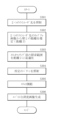
- FIG. 16 is a flowchart showing an example of processing for generating a depth image in the image processing device according to the fifth embodiment.
- step S301 two line laser beams L1 and L2 are emitted by the laser 30 and the scanning mechanism 31.
- the Z distance estimator 60 estimates the distance Z to the wall 70 from the captured images of the two line laser beams L1 and L2 (step S302).
- the search range of the stereo matching unit 22 is optimized to the distance Z (step S303).
- a predetermined pattern is projected onto the wall 70 by the pattern projector 40 (step S304).
- stereo ranging is performed by the stereo matching unit 22 (step S305).
- the stereo matching unit 22 generates robust depth images (step S306).
- the present technology can also have the following configuration.
- the present technology having the following configuration, the first information acquired by imaging the first laser beam and the second laser beam with the image sensor at the first depth of water, and the measurement target object with the image sensor.
- the image sensor at the second water depth based on the second information obtained by imaging the first laser light and the second laser light with the image sensor at the second water depth, which is the water depth at the time of imaging.
- Correction data used to correct the distortion of the captured image due to is generated. This makes it possible to correctly correct the distortion of the captured image according to the depth of water.
- an image sensor that captures an image of an object to be measured in water; a first laser light source that emits a first laser beam in water; a second laser light source that emits a second laser light from a position in water different from that of the first laser light source; First information acquired by imaging the first laser beam and the second laser beam with the image sensor at a first water depth, and water depth when the image sensor images the measurement target.
- the image sensor at the second water depth based on the second information obtained by imaging the first laser light and the second laser light with the image sensor at the second water depth and a correction data generation unit that generates correction data used to correct distortion of a captured image.
- a distance estimating unit that estimates the distance to the measurement object based on the captured image of the first laser beam and the second laser beam by the image sensor at the second water depth
- the image processing device according to (4) above, wherein the depth image generation unit sets a search range of the measurement object for which the depth image is generated, based on the distance estimated by the distance estimation unit.
- the correction data generation unit acquires, as the first information, information on a first intersection point between the first laser beam and the second laser beam imaged by the image sensor at the first water depth.
- information on a second intersection point corresponding to the first intersection point of the first laser beam and the second laser beam imaged by the image sensor at the second depth of water is transmitted to the second depth of water.
- the image processing device Obtained as information, and generating the correction data based on the information of the amount of movement between the first intersection point and the second intersection point on the image captured by the image sensor.
- the image processing device according to any one of the above. (7) a first scanning mechanism that scans the first laser beam emitted from the first laser light source; a second scanning mechanism that scans the second laser beam emitted from the second laser light source,
- the correction data generation unit is configured to operate the first scanning mechanism and the The image processing apparatus according to (6) above, which scan-controls the second scanning mechanism.
- the information on the first intersection point and the information on the second intersection point are respectively information on the first scanning angle by the first scanning mechanism and information on the second scanning angle by the second scanning mechanism.
- the image processing apparatus further comprising: a correction data holding unit that holds the correction data in association with the .
- the image processing device according to (8), wherein the correction data holding unit holds the correction data in association with the depth information of the second water depth.
- the image processing apparatus according to any one of (1) to (9) above, further comprising a pattern projector that irradiates the measurement object with a predetermined pattern.
- the image processing apparatus according to any one of (1) to (10) above, further comprising a plurality of pattern projectors that irradiate the object to be measured with predetermined patterns having different wavelength bands.
- the correction data generation unit estimates turbidity in water based on the captured image of the first laser beam and the second laser beam by the image sensor at the second water depth, and The image processing apparatus according to (11) above, wherein one of the plurality of pattern projectors is selected as a pattern projector that emits the predetermined pattern based on turbidity.
- (13) capturing an image of an object to be measured in water with an image sensor; emitting a first laser beam in water; emitting a second laser beam from a position in water different from that of the first laser light source; First information acquired by imaging the first laser beam and the second laser beam with the image sensor at a first water depth, and water depth when the image sensor images the measurement target.
- An image processing method comprising: generating correction data used for correcting distortion of a captured image. (14) emitting a first laser beam in water; emitting a second laser beam from a position in water different from that of the first laser light source; The first information acquired by imaging the first laser beam and the second laser beam with the image sensor at the first water depth, and the water depth when the image sensor captures the image of the measurement target. imaging by the image sensor at the second depth of water based on second information acquired by imaging the first laser beam and the second laser beam by the image sensor at the second depth of water; A program for causing a computer to execute processing including generating correction data used to correct image distortion.
Landscapes
- Engineering & Computer Science (AREA)
- Physics & Mathematics (AREA)
- General Physics & Mathematics (AREA)
- Theoretical Computer Science (AREA)
- Computer Vision & Pattern Recognition (AREA)
- Optics & Photonics (AREA)
- Length Measuring Devices By Optical Means (AREA)
- Image Analysis (AREA)
Priority Applications (1)
| Application Number | Priority Date | Filing Date | Title |
|---|---|---|---|
| US18/291,314 US12705713B2 (en) | 2021-08-20 | 2022-03-16 | Image processor, image processing method, and program |
Applications Claiming Priority (2)
| Application Number | Priority Date | Filing Date | Title |
|---|---|---|---|
| JP2021134585A JP7722039B2 (ja) | 2021-08-20 | 2021-08-20 | 画像処理装置、および画像処理方法ならびにプログラム |
| JP2021-134585 | 2021-08-20 |
Publications (1)
| Publication Number | Publication Date |
|---|---|
| WO2023021765A1 true WO2023021765A1 (ja) | 2023-02-23 |
Family
ID=85240286
Family Applications (1)
| Application Number | Title | Priority Date | Filing Date |
|---|---|---|---|
| PCT/JP2022/011861 Ceased WO2023021765A1 (ja) | 2021-08-20 | 2022-03-16 | 画像処理装置、および画像処理方法ならびにプログラム |
Country Status (3)
| Country | Link |
|---|---|
| US (1) | US12705713B2 (cg-RX-API-DMAC7.html) |
| JP (1) | JP7722039B2 (cg-RX-API-DMAC7.html) |
| WO (1) | WO2023021765A1 (cg-RX-API-DMAC7.html) |
Families Citing this family (1)
| Publication number | Priority date | Publication date | Assignee | Title |
|---|---|---|---|---|
| US12375791B2 (en) * | 2023-09-13 | 2025-07-29 | Voyis Imaging Inc. | System for underwater depth perception having multiple image sensors |
Citations (6)
| Publication number | Priority date | Publication date | Assignee | Title |
|---|---|---|---|---|
| JP2008236635A (ja) * | 2007-03-23 | 2008-10-02 | Olympus Imaging Corp | 電子撮像装置 |
| JP2009200589A (ja) * | 2008-02-19 | 2009-09-03 | Sanyo Electric Co Ltd | 画像処理装置およびその色補正撮影方法 |
| JP2011248414A (ja) * | 2010-05-22 | 2011-12-08 | Japan Agengy For Marine-Earth Science & Technology | 画像処理システム及び方法 |
| JP2012018147A (ja) * | 2010-07-09 | 2012-01-26 | Public Works Research Institute | 水中構造物点検システム及び画像処理装置 |
| JP2016099140A (ja) * | 2014-11-18 | 2016-05-30 | 朝日航洋株式会社 | 水底観測システム |
| WO2017145202A1 (ja) * | 2016-02-26 | 2017-08-31 | パナソニックIpマネジメント株式会社 | 検査システム、検査方法および検査プログラム |
-
2021
- 2021-08-20 JP JP2021134585A patent/JP7722039B2/ja active Active
-
2022
- 2022-03-16 WO PCT/JP2022/011861 patent/WO2023021765A1/ja not_active Ceased
- 2022-03-16 US US18/291,314 patent/US12705713B2/en active Active
Patent Citations (6)
| Publication number | Priority date | Publication date | Assignee | Title |
|---|---|---|---|---|
| JP2008236635A (ja) * | 2007-03-23 | 2008-10-02 | Olympus Imaging Corp | 電子撮像装置 |
| JP2009200589A (ja) * | 2008-02-19 | 2009-09-03 | Sanyo Electric Co Ltd | 画像処理装置およびその色補正撮影方法 |
| JP2011248414A (ja) * | 2010-05-22 | 2011-12-08 | Japan Agengy For Marine-Earth Science & Technology | 画像処理システム及び方法 |
| JP2012018147A (ja) * | 2010-07-09 | 2012-01-26 | Public Works Research Institute | 水中構造物点検システム及び画像処理装置 |
| JP2016099140A (ja) * | 2014-11-18 | 2016-05-30 | 朝日航洋株式会社 | 水底観測システム |
| WO2017145202A1 (ja) * | 2016-02-26 | 2017-08-31 | パナソニックIpマネジメント株式会社 | 検査システム、検査方法および検査プログラム |
Also Published As
| Publication number | Publication date |
|---|---|
| US20250117900A1 (en) | 2025-04-10 |
| JP2023028713A (ja) | 2023-03-03 |
| JP7722039B2 (ja) | 2025-08-13 |
| US12705713B2 (en) | 2026-08-11 |
Similar Documents
| Publication | Publication Date | Title |
|---|---|---|
| JP5635218B1 (ja) | 空間コード化スライド画像に対するパターンのアライメント方法およびシステム | |
| US9599462B2 (en) | Three-dimensional shape measurement apparatus and control method thereof | |
| JP6299111B2 (ja) | レーザ加工装置 | |
| US8295587B2 (en) | Image processing apparatus, image processing method, image processing program and position detecting apparatus as well as mobile object having the same | |
| US9858684B2 (en) | Image processing method and apparatus for calibrating depth of depth sensor | |
| JP3930482B2 (ja) | 3次元視覚センサ | |
| JP6041513B2 (ja) | 画像処理装置、画像処理方法及びプログラム | |
| US20110096182A1 (en) | Error Compensation in Three-Dimensional Mapping | |
| US8451878B2 (en) | Surface profile inspection device | |
| US11620732B2 (en) | Multi-projection system, image projection method and projector | |
| US10277884B2 (en) | Method and apparatus for acquiring three-dimensional image, and computer readable recording medium | |
| JP6940843B2 (ja) | 水底観測システム | |
| KR101597163B1 (ko) | 스테레오 카메라 교정 방법 및 장치 | |
| JP2009115512A (ja) | 物品検査方法 | |
| JP2018044942A (ja) | カメラパラメータ算出装置、カメラパラメータ算出方法、プログラム、及び記録媒体 | |
| KR20200032442A (ko) | 자기보정이 가능한 3차원 정보 생성 장치 및 방법 | |
| JP2023028713A (ja) | 画像処理装置、および画像処理方法ならびにプログラム | |
| JP4077755B2 (ja) | 位置検出方法、その装置及びそのプログラム、並びに、較正情報生成方法 | |
| JP6241083B2 (ja) | 撮像装置及び視差検出方法 | |
| JP6969619B2 (ja) | 校正方法 | |
| US20250054190A1 (en) | Camera calibration method, and stereo camera device | |
| JP2023028713A5 (cg-RX-API-DMAC7.html) | ||
| JP5471889B2 (ja) | 表面形状計測方法およびその装置 | |
| JP6604934B2 (ja) | 点群画素位置決定装置、方法、及びプログラム | |
| JP2008232779A (ja) | タイヤ形状検出装置 |
Legal Events
| Date | Code | Title | Description |
|---|---|---|---|
| 121 | Ep: the epo has been informed by wipo that ep was designated in this application |
Ref document number: 22858090 Country of ref document: EP Kind code of ref document: A1 |
|
| WWE | Wipo information: entry into national phase |
Ref document number: 18291314 Country of ref document: US |
|
| NENP | Non-entry into the national phase |
Ref country code: DE |
|
| 122 | Ep: pct application non-entry in european phase |
Ref document number: 22858090 Country of ref document: EP Kind code of ref document: A1 |
|
| WWP | Wipo information: published in national office |
Ref document number: 18291314 Country of ref document: US |