WO2023021588A1 - 着磁方法、着磁装置、電動機、圧縮機および冷凍サイクル装置 - Google Patents
着磁方法、着磁装置、電動機、圧縮機および冷凍サイクル装置 Download PDFInfo
- Publication number
- WO2023021588A1 WO2023021588A1 PCT/JP2021/030096 JP2021030096W WO2023021588A1 WO 2023021588 A1 WO2023021588 A1 WO 2023021588A1 JP 2021030096 W JP2021030096 W JP 2021030096W WO 2023021588 A1 WO2023021588 A1 WO 2023021588A1
- Authority
- WO
- WIPO (PCT)
- Prior art keywords
- magnetizing
- coil
- voltage
- phase coil
- rotor
- Prior art date
- Legal status (The legal status is an assumption and is not a legal conclusion. Google has not performed a legal analysis and makes no representation as to the accuracy of the status listed.)
- Ceased
Links
Images





Classifications
-
- H—ELECTRICITY
- H02—GENERATION; CONVERSION OR DISTRIBUTION OF ELECTRIC POWER
- H02K—DYNAMO-ELECTRIC MACHINES
- H02K15/00—Processes or apparatus specially adapted for manufacturing, assembling, maintaining or repairing of dynamo-electric machines
- H02K15/02—Processes or apparatus specially adapted for manufacturing, assembling, maintaining or repairing of dynamo-electric machines of stator or rotor bodies
- H02K15/03—Processes or apparatus specially adapted for manufacturing, assembling, maintaining or repairing of dynamo-electric machines of stator or rotor bodies having permanent magnets
Definitions
- the present disclosure relates to magnetization methods, magnetization devices, electric motors, compressors, and refrigeration cycle devices.
- a method of magnetizing the permanent magnets of an electric motor a method is known in which a permanent magnet before magnetization is incorporated into the rotor of the electric motor, and a magnetizing current is applied to the coil of the stator to magnetize the permanent magnet.
- a magnetization method is called built-in magnetization.
- An object of the present disclosure is to more uniformly magnetize the permanent magnet while suppressing damage to the coils of the electric motor.
- the magnetization method of the present disclosure is a magnetization method for magnetizing a permanent magnet of an electric motor.
- the electric motor has a rotor having permanent magnets and rotatable about an axis, a stator having a stator core surrounding the rotor, and coils wound around the stator core.
- the magnetization method includes a first magnetization step of applying a magnetizing voltage to the coil while the rotor is rotated in a first direction from the reference position by an angle ⁇ , and a first magnetization step of applying a magnetization voltage to the coil, and rotating the rotor in a second direction from the reference position. and a second magnetizing step of applying a magnetizing voltage to the coil while it is rotated by an angle ⁇ .
- the method has a step of measuring the inductance of the coil and a step of determining a magnetizing voltage in the second magnetizing step based on the measured inductance.
- the magnetizing voltage in the second magnetizing step is determined based on the coil inductance measured before the second magnetizing step, the magnetizing voltage corresponding to the rotational angle deviation of the rotor is determined. can be applied. As a result, the permanent magnets can be more uniformly magnetized while suppressing damage to the coils of the electric motor.
- FIG. 2 is a cross-sectional view showing the electric motor of Embodiment 1;
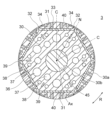
- FIG. 2 is a cross-sectional view showing the rotor of Embodiment 1;
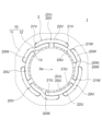
- FIG. 2 is a top view showing the stator of Embodiment 1;
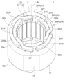
- FIG. 2 is a perspective view showing the stator of Embodiment 1;
- FIG. 1 is a perspective view showing an electric motor according to Embodiment 1;
- FIG. FIG. 2A is a diagram showing the magnetizing device of Embodiment 1, and
- FIG. 2B is a graph showing a magnetizing current;
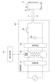
- FIG. 4 is a schematic diagram showing a magnetizing power source and a voltage determining section according to Embodiment 1.
- FIG. FIG. 1A shows a general magnetizing yoke, and FIG.
- FIG. 1B shows a magnetizing device using the magnetizing yoke.
- 4A, 4B, and 4C are schematic diagrams for explaining the electromagnetic force acting on the coil due to the magnetizing current;
- FIG. 4A and 4B are schematic diagrams showing a magnetization method according to the first embodiment;
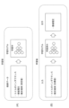
- FIG. 4 is a schematic diagram (A) showing a connection state between a magnetizing power source and a coil according to Embodiment 1, and schematic diagrams (B) and (C) for explaining first and second magnetizing steps.
- 4 is a graph showing the relationship between the rotor angle in the magnetization process and the magnetomotive force required to obtain a magnetization rate of 99%.
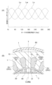
- FIG. 4A is a graph showing the relationship between the angle of the rotor and the inductance of each phase coil
- FIG. 4B is a schematic diagram showing the positional relationship between the rotor and the center of the U-phase coil.
- FIG. 4 is a schematic diagram for explaining a method of measuring inductance in Embodiment 1; 4A and 4B are schematic diagrams for explaining the concept of machine learning according to the first embodiment;
- FIG. 4 is a schematic diagram for explaining a method of measuring interlinkage magnetic flux in Embodiment 1;
- 3 is a functional block diagram showing a voltage determining section of Embodiment 1;
- FIG. 3 is a block diagram showing a hardware configuration example of a voltage determining unit according to Embodiment 1;
- FIG. 4 is a flow chart showing a magnetization method of Embodiment 1.
- FIG. 7A and 7B are schematic diagrams for explaining the concept of machine learning according to the second embodiment;
- FIG. 9 is a schematic diagram for explaining a method of measuring coil resistance in Embodiment 2;
- FIG. 10 is a functional block diagram showing a voltage determining section according to Embodiment 2;
- 4 is a graph showing the relationship between inductance and magnetizing voltage; 8 is a flow chart showing a magnetization method according to Embodiment 2.
- FIG. FIG. 11 is a functional block diagram showing a voltage determining section according to Embodiment 3; It is a top view which shows the stator of a modification. It is a perspective view which shows the stator of a modification.
- FIG. 11 is a functional block diagram showing a voltage determining section according to Embodiment 3; It is a top view which shows the stator of a modification. It is a perspective view which shows the stator of a modification.
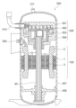
- FIG. 7A is a schematic diagram showing a connection state between a magnetizing power supply and a coil of a modification, and schematic diagrams (B) and (C) are for explaining the first and second magnetizing steps. It is a figure which shows the compressor to which the electric motor of each embodiment and a modification is applicable.
- FIG. 30 is a diagram showing a refrigeration cycle apparatus having the compressor of FIG. 29;
- FIG. 1 is a cross-sectional view showing electric motor 100 of Embodiment 1.
- FIG. 1 has a rotatable rotor 3 and a stator 1 surrounding the rotor 3 .
- An air gap of 0.25 to 1.25 mm is provided between the stator 1 and rotor 3 .
- FIG. 1 is a cross section perpendicular to the axial direction.
- FIG. 2 is a sectional view showing the rotor 3.
- the rotor 3 has a rotor core 30 and permanent magnets 40 attached to the rotor core 30 .
- Rotor core 30 has a cylindrical shape centered on axis Ax.
- the rotor core 30 is formed by stacking magnetic steel sheets in the axial direction and integrally fixing them by caulking, rivets, or the like.
- the plate thickness of the electromagnetic steel plate is, for example, 0.1 to 0.7 mm.
- the rotor core 30 has an outer circumference 30a and an inner circumference 30b.
- a shaft 45 is fixed to the inner circumference 30b of the rotor core 30 by press fitting.
- a central axis of the shaft 45 coincides with the above-described axis Ax.
- the rotor core 30 has a plurality of magnet insertion holes 31 along the outer circumference 30a.
- six magnet insertion holes 31 are arranged at regular intervals in the circumferential direction.
- One permanent magnet 40 is arranged in each magnet insertion hole 31 .
- One permanent magnet 40 constitutes one magnetic pole. Since the number of permanent magnets 40 is six, the number of poles P of the rotor 3 is six. However, the number of poles P of the rotor 3 is not limited to 6, and may be 2 or more. Also, two or more permanent magnets 40 may be arranged in one magnet insertion hole 31, and one magnetic pole may be configured by the two or more permanent magnets 40. FIG.
- each magnet insertion hole 31 in the circumferential direction is the pole center.
- a straight line in the radial direction passing through the pole center is defined as a magnetic pole center line C.
- the magnetic pole centerline C is the d-axis of the rotor 3 .
- An interpolar portion N is provided between adjacent magnet insertion holes 31 .
- the permanent magnet 40 is a flat member having a width in the circumferential direction and a thickness in the radial direction.
- Permanent magnet 40 is a neodymium rare earth magnet containing neodymium (Nd), iron (Fe) and boron (B), and may contain heavy rare earth elements such as dysprosium (Dy) or terbium (Tb). good.
- the permanent magnet 40 is magnetized in its thickness direction, that is, in its radial direction. Permanent magnets 40 adjacent in the circumferential direction have magnetization directions opposite to each other.
- a flux barrier 32 is formed at each end of the magnet insertion hole 31 in the circumferential direction.
- the flux barrier 32 is a gap radially extending from the circumferential end of the magnet insertion hole 31 toward the outer circumference of the rotor core 30 .
- the flux barrier 32 has the effect of suppressing leakage flux between adjacent magnetic poles.
- a slit 33 is formed radially outside the magnet insertion hole 31 .
- eight radially long slits 33 are formed symmetrically with respect to the magnetic pole center line C.
- Two side slits 34 that are long in the circumferential direction are formed on both sides of the eight slits 33 in the circumferential direction.
- the number and arrangement of the slits 33 are arbitrary.
- the rotor core 30 may not have the slits 33 and the side slits 34 .
- a crimped portion 39 for integrally fixing the electromagnetic steel plates that constitute the rotor core 30 is formed on a straight line in the radial direction that passes through the portion N between the poles.
- the arrangement of the crimped portion 39 is not limited to this position.
- a through hole 36 is formed radially inside the magnet insertion hole 31 , and a through hole 37 is formed radially inside the crimped portion 39 .
- Through holes 38 are formed on both sides of the crimped portion 39 in the circumferential direction.
- the through-holes 36, 37, 38 all extend from one axial end to the other axial end of the rotor core 30 and are used as coolant channels or rivet holes.
- the arrangement of the through holes 36, 37, 38 is not limited to these positions. Also, the rotor core 30 may not have the through holes 36 , 37 , 38 .
- the stator 1 has an annular stator core 10 centered on the axis Ax and a coil 2 wound around the stator core 10 .
- the stator core 10 is formed by laminating a plurality of magnetic steel sheets in the axial direction and integrally fixing them by caulking or the like.
- the plate thickness of the electromagnetic steel plate is, for example, 0.1 to 0.7 mm.
- the stator core 10 has an annular core back 11 and a plurality of teeth 12 extending radially inward from the core back 11 .
- the core back 11 has an outer peripheral surface 14 which is a cylindrical surface centered on the axis Ax.
- the outer peripheral surface 14 of the core back 11 is fitted to the inner peripheral surface of the cylindrical shell 80 .
- the shell 80 is a part of the compressor 8 (FIG. 6(A)) and is made of a magnetic material.
- the teeth 12 are formed at regular intervals in the circumferential direction.
- a tooth tip portion having a wide width in the circumferential direction is formed at the radially inner tip of the tooth 12 .
- a tooth tip portion of the tooth 12 faces the rotor 3 .
- Coils 2 are wound around the teeth 12 by distributed winding. Although the number of teeth 12 is 18 here, it may be 2 or more.
- a slot 13 is formed between adjacent teeth 12 .
- the number of slots 13 is the same as the number of teeth 12, here eighteen.
- the coil 2 is accommodated in the slot 13 .
- a D cut portion 15 is formed as a plane portion parallel to the axis Ax on the outer peripheral surface 14 of the core back 11 .
- the D-cut portion 15 extends from one axial end to the other axial end of the stator core 10 .
- the D-cut portions 15 are formed at four locations at intervals of 90 degrees around the axis Ax.
- a gap is formed between the D-cut portion 15 and the inner peripheral surface of the shell 80, and this gap serves as a flow path for the coolant to flow in the axial direction.
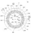
- FIG. 3 is a top view showing the stator 1.
- the stator core 10 is wound with a U-phase coil 2U as a first-phase coil, a V-phase coil 2V as a second-phase coil, and a W-phase coil 2W as a third-phase coil.
- Coils 2U, 2V and 2W are referred to as coil 2 when there is no need to distinguish between them.
- Each of the coils 2U, 2V, 2W has a conductor made of aluminum or copper and an insulating coating covering the conductor.
- the coil 2U is positioned radially innermost, and the coil 2V is positioned radially outermost.
- the coil 2W is located radially outside the coil 2U and radially inside the coil 2V.
- the coil 2U has three winding portions 20U.
- the three winding portions 20U are arranged at intervals of 120 degrees in the circumferential direction around the axis Ax.
- Each winding portion 20U is wound across three teeth 12 .
- Each winding portion 20U has two coil sides 21U that are inserted into slots 13 and two coil ends 22U that extend along the end surface of stator core 10 .
- the coil 2V has three winding portions 20V.
- the three winding portions 20V are arranged at intervals of 120 degrees in the circumferential direction around the axis Ax.
- Each winding portion 20V is wound across three teeth 12 .
- Each winding portion 20V has two coil sides 21V inserted into the slots 13 and two coil ends 22V extending along the end surface of the stator core 10 .
- the coil 2W has three winding portions 20W.
- the three winding portions 20W are arranged at intervals of 120 degrees in the circumferential direction about the axis Ax.
- Each winding portion 20W is wound across three teeth 12 .
- Each winding portion 20W has two coil sides 21W inserted into slots 13 and two coil ends 22W extending along the end surface of stator core 10 .
- each coil side is inserted into all the slots 13 of the stator core 10 .
- the number of winding portions 20U, the number of winding portions 20V, and the number of winding portions 20W are all half the number of poles P of the rotor 3.
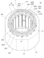
- FIG. 4 is a perspective view showing the stator 1.
- FIG. Coil ends 22U, 22W and 22V are arranged on end faces 10a and 10b of the stator core 10 in the axial direction.
- the coil end 22U is arranged radially innermost
- the coil end 22V is arranged radially outermost
- the coil end 22W is routed from the radially outer side of the coil end 22U to the radially inner side of the coil end 22V.
- FIG. 5 is a perspective view showing the process of assembling the rotor 3 inside the stator 1.
- FIG. 1 When the rotor 3 is incorporated into the stator 1, the permanent magnets 40 of the rotor 3 are not yet magnetized. Therefore, when the rotor 3 is incorporated into the stator 1, the magnetic attraction force does not act between them, and the assembling work can be easily performed.
- FIG. 6A shows a magnetizing device 6 for magnetizing the permanent magnet 40.
- the rotor 3 is incorporated into the stator 1 to configure the electric motor 100
- the permanent magnet 40 is magnetized with the electric motor 100 incorporated into the compressor 8 .
- the permanent magnet before being magnetized is a magnetic material, it will be referred to as a "permanent magnet" for convenience of explanation.
- the magnetizing device 6 has a magnetizing power source 60 as a power source device and a rotor positioning mechanism 68 .
- the magnetizing power supply 60 and the rotor positioning mechanism 68 may be operated by an operator, or a host controller may be provided to control the operations of the magnetizing power supply 60 and the rotor positioning mechanism 68 .
- the rotor positioning mechanism 68 positions the electric motor 100 inside the compressor 8 in the circumferential direction.
- the rotor positioning mechanism 68 has, for example, a servomotor.
- the permanent magnet 40 is magnetized, the lower end 81 of the shell 80 of the compressor 8 is open, and the rotor positioning mechanism 68 is fixed to the shaft 45 of the electric motor 100 via the lower end 81 of the shell 80. connected by a fixture.
- the magnetizing power supply 60 is connected to the coil 2 of the electric motor 100 inside the compressor 8 by wires L1 and L2.
- a magnetizing power supply 60 applies a magnetizing voltage to the coil 2 , thereby causing a magnetizing current to flow through the coil 2 .
- the magnetizing current has a waveform with a high peak of several kA, for example, as shown in FIG. 6B.
- a voltage determination unit 70 for determining a magnetizing voltage is connected to the magnetizing power supply 60 .
- FIG. 7 is a block diagram showing the configuration of the magnetizing device 6.
- a magnetizing power source 60 of the magnetizing device 6 has a control circuit 61 , a booster circuit 62 , a rectifying circuit 63 , a capacitor 64 and a switch 65 .
- the control circuit 61 controls the phase of the AC voltage supplied from the AC power supply, which is the commercial power supply.
- the booster circuit 62 boosts the output voltage of the control circuit 61 .
- the rectifier circuit 63 converts the AC voltage output from the booster circuit 62 into a DC voltage.
- Capacitor 64 stores charge. The switch 65 is turned on when the charge accumulated in the capacitor 64 is discharged.
- a magnetizing current generated by the magnetizing power supply 60 is supplied to the coil 2 of the electric motor 100 via wires L1 and L2.
- the charge accumulated in the capacitor 64 is discharged to the coil 2 by turning on the switch 65 .
- the magnetizing voltage is applied to the coil 2, and the magnetizing current shown in FIG.
- the state of connection between the magnetizing power source 60 and the coils 2U, 2V and 2W will be described later with reference to FIG. 11(A).
- the magnetizing voltage applied to the coil 2 is determined by the charging voltage of the capacitor 64.
- the charging voltage of capacitor 64 is controlled by booster circuit 62 .
- the voltage of the booster circuit 62 is determined by the voltage determining section 70 .
- the voltage determination unit 70 may be incorporated in the magnetizing power supply 60, or may be a personal computer connected to the magnetizing power supply 60 via a network.
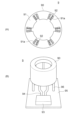
- FIG. 8A is a sectional view showing the magnetizing yoke 90
- FIG. 8B is a diagram showing the magnetizing device 9 including the magnetizing yoke 90.
- the magnetizing yoke 90 has an annular core member 91 made of a magnetic material and a coil 92 wound around the core member 91 .
- the core member 91 has, for example, six slots 91a in the circumferential direction, and a coil 92 is accommodated in each slot 91a.
- the magnetizing device 9 includes a magnetizing power supply 93, a lead wire 94 connecting the magnetizing power supply 93 and the coil 92 (FIG. 8A), and a magnetizing yoke 90. It has supporting legs 96 and a base 95 supporting them.
- the rotor 3 having the permanent magnets 40 before magnetization is arranged inside the magnetizing yoke 90 .
- a magnetizing current is passed through the coil 92 from the magnetizing power source 93 to generate a magnetizing magnetic field in the magnetizing yoke 90 to magnetize the permanent magnets 40 of the rotor 3 .
- the magnetizing yoke 90 is designed exclusively for magnetizing the permanent magnet 40, the coil 92 can be made sufficiently thick. Therefore, even if an electromagnetic force is generated by a magnetizing current flowing through the coil 92, the coil 92 is unlikely to be damaged.
- iron powder or the like may adhere to the rotor 3 due to the magnetic force of the permanent magnet 40 . If the rotor 3 is assembled into the stator 1 with iron powder or the like adhering to it, the performance of the electric motor 100 will be degraded.
- the built-in magnetization performed with the rotor 3 built into the stator 1 greatly improves the assembling efficiency of the electric motor 100 .
- a magnetizing current is passed through the coil 2 of the stator 1, there are the following problems.
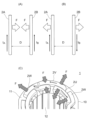
- 9A and 9B are schematic diagrams showing the principle of electromagnetic force generation during magnetization.
- a current I A [A] flows through the conductor 2A
- a current I B [A] flows through the conductor 2B.
- D [m] be the distance between .
- F ⁇ 0 ⁇ IA ⁇ IB /(2 ⁇ D) (1)
- ⁇ 0 is the magnetic permeability of a vacuum, and
- ⁇ 0 4 ⁇ 10 ⁇ 7 [H/m].
- FIG. 9(C) is a schematic diagram showing the electromagnetic forces acting on the coils 2U, 2V, and 2W.
- Currents flow in opposite directions in the portion where the coil 2U and the coil 2V face each other and the portion where the coil 2U and the coil 2W face each other, so that a large electromagnetic force acts in a mutually repulsive direction. Since the current flows in the same direction in the portion where the coil 2V and the coil 2W face each other, a small electromagnetic force acts in the direction in which they are attracted to each other.
- the current flowing through the coil 2 reaches several kA during the magnetization process. Due to this current, the electromagnetic force shown in FIG. 9(C) momentarily acts on the coil 2, so there is a possibility that the coil 2 will be damaged. Damage to the coil 2 is, for example, insulation failure due to damage or deformation of the conductor of the coil 2 or damage to the coating.
- the electromagnetic force can be reduced by increasing the distance D between the conductors 2A, 2B or by decreasing the currents IA , IB .
- widening the distance D between the conductors 2A and 2B results in widening the mutual distance between the coils 2, resulting in a decrease in the space factor in the slot 13 or an increase in the circumference of the coil 2, which is not practical. Therefore, it is desirable to suppress the currents I A and I B , that is, the magnetizing currents flowing through the coil 2 .
- Embodiment 1 in order to uniformly magnetize the permanent magnets 40 with the least possible magnetizing current, the magnetization process is performed twice while changing the rotation angle of the rotor 3 .
- Such a magnetization method is called "double magnetization". Note that the number of magnetization steps may be more than two.
- Twice magnetization is performed as follows. First, the rotor 3 having the permanent magnets 40 before being magnetized is incorporated into the stator 1 to configure the electric motor 100 , and the electric motor 100 is incorporated into the compressor 8 . Also, the wires L1 and L2 of the magnetizing power supply 60 are connected to the coil 2 of the electric motor 100 .
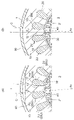
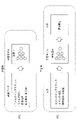
- FIG. 10A and (B) are schematic diagrams showing the positional relationship between the stator 1 and the rotor 3 in each magnetization process.
- FIG. 10A a straight line in the radial direction passing through the center of the magnetizing magnetic flux is called a magnetizing magnetic flux center line T. As shown in FIG. 10A, a straight line in the radial direction passing through the center of the magnetizing magnetic flux is called a magnetizing magnetic flux center line T. As shown in FIG.
- the permanent magnet 40 is magnetized while facing the winding portion 20U of the coil 2U.
- the permanent magnet 40 is magnetized with the pole center of the permanent magnet 40 facing the center tooth 12 of the three teeth 12 over which the winding portion 20U of the coil 2U straddles.
- the magnetizing magnetic flux center line T passes through the center of the center teeth 12 in the circumferential direction.
- the rotor 3 is rotated so that the magnetic pole center line C of the permanent magnet 40, that is, the d-axis, forms an angle ⁇ with respect to the magnetizing magnetic flux center line T. Rotate in direction 1.
- the first direction here is counterclockwise in the drawing.
- the angle ⁇ is, for example, 5 to 10 degrees.
- a magnetizing current is supplied from the magnetizing power source 60 to the coils 2U, 2V and 2W.
- the rotor 3 is rotated so that the magnetic pole center line C of the permanent magnet 40, that is, the d-axis, forms an angle ⁇ with respect to the magnetized magnetic flux center line T. Rotate in two directions.
- the second direction is here clockwise in the drawing.
- the angle .theta. is the same as the angle .theta. in the first magnetization step, and is, for example, 5 to 10 degrees.
- a magnetizing current is supplied from the magnetizing power source 60 to the coils 2U, 2V and 2W.
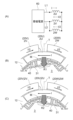
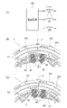
- FIG. 11(A) is a diagram showing the connection state between the magnetizing power source 60 of the magnetizing device 6 and the coils 2U, 2V, and 2W.
- the coils 2V and 2W are connected in parallel and connected in series with the coil 2U. This connection can be made, for example, with a glass terminal 309 shown in FIG. Assuming that the magnetizing current flowing through the coil 2U is I, the magnetizing current flowing through the coil 2V is I/2, and the magnetizing current flowing through the coil 2W is also I/2.
- FIG. 11(B) is a schematic diagram showing the magnetizing magnetic flux in the first magnetizing step.
- the first region R1 from the center to one end of the permanent magnet 40 faces the center of the winding portion 20U of the coil 2U. Since the magnetizing current I flows through the coil 2U and the magnetizing current I/2 flows through the coils 2V and 2W, a large amount of magnetic flux is generated in the first region R1 of the permanent magnet 40 facing the winding portion 20U of the coil 2U. As a result, the first region R1 of the permanent magnet 40 is magnetized.
- FIG. 11(C) is a schematic diagram showing the magnetizing magnetic flux in the second magnetizing step.
- the second region R2 from the center to the other end of the permanent magnet 40 faces the center of the winding portion 20U of the coil 2U. Since the magnetizing current I flows through the coil 2U and the magnetizing current I/2 flows through the coils 2V and 2W, a large amount of magnetic flux is generated in the second region R2 of the permanent magnet 40 facing the winding portion 20U of the coil 2U. As a result, the second region R2 of the permanent magnet 40 is magnetized.
- the direction of the magnetizing magnetic flux M and the direction of easy magnetization of the permanent magnet 40 can be made parallel to each other for magnetization.
- the direction of easy magnetization of the permanent magnet 40 is the thickness direction of the permanent magnet 40 .
- FIG. 12 shows the rotation angle ⁇ from the reference position of the rotor 3 in the first magnetization step and the second magnetization step, and the magnetomotive force required to obtain the magnetization rate of 99.7 [%] of the permanent magnet 40. is a graph showing the relationship between This graph is obtained by magnetic field analysis.
- the rotation angle ⁇ is the angle from the above-mentioned reference position (magnetizing magnetic flux center line T shown in FIG. 10A) to the d-axis of the rotor 3, and varies from 0 degrees to 12.5 degrees.
- the magnetization rate [%] indicates the degree of magnetization when the complete magnetization is 100 [%].
- the magnetomotive force [kA T] is the product of the current [kA] flowing through the coil 2 and the number of turns [T] of the coil 2.
- the current [kA] flowing through the U-phase coil 2U and the number of turns of the coil 2U It is the product of [T].
- the magnetomotive force required to obtain the magnetization rate of 99.7[%] of the permanent magnet 40 is referred to as magnetizing magnetomotive force.
- the magnetomotive force required to obtain a magnetization rate of 99.7 [%] decreases as the rotation angle ⁇ increases, reaches its minimum when the rotation angle ⁇ is 7.5 degrees, and thereafter reaches the rotation angle ⁇ increases with an increase in Therefore, the rotation angle ⁇ of the rotor 3 in the first magnetization process and the second magnetization process is most preferably 7.5 degrees.
- a cogging torque is generated by the attractive force between the already magnetized first region R1 of the permanent magnet 40 and the stator 1, so that the rotation angle ⁇ of the rotor 3 is likely to shift. .
- the permanent magnets 40 are not uniformly magnetized, and the magnetic force of each permanent magnet 40 may vary. Variation in magnetic force of permanent magnet 40 leads to variation in efficiency and output of electric motor 100 .
- the inductance of the coil 2 is measured before the second magnetization step, and the magnetizing voltage is adjusted based on the inductance.
- the inductances Lu, Lw, and Lv of the coils 2U, 2V, and 2W can be expressed by the following equations (1), (2), and (3) using the rotation angle ⁇ from the reference position of the rotor 3. can.
- la [H] is the leakage inductance per phase
- La [H] is the average effective inductance per phase
- Las[H] is the amplitude of the effective inductance per phase.
- FIG. 13(A) is a graph representing the above equations (1), (2), and (3).
- the vertical axis indicates the inductances Lu, Lw, and Lv of the coils 2U, 2V, and 2W, and the horizontal axis indicates the rotation angle ⁇ of the rotor 3 from the reference position.
- the rotation angle .theta. is the lead angle of the d-axis with respect to the center of the winding portion 20U of the U-phase coil 2U (that is, the magnetizing magnetic flux center line T).
- the inductance shown in FIG. 13(A) is the inductance when a minute current is passed through the coils 2U, 2V, and 2W, and does not consider the decrease in inductance due to magnetic saturation.
- the inductances of the coils 2U, 2V, and 2W all change sinusoidally with changes in the rotation angle ⁇ of the rotor 3.
- stator core 10 When the current flowing through the coil 2 increases, magnetic saturation in the stator core 10 reduces the flowability of the magnetic flux. Inductance can be measured without saturation.
- the magnetizing voltage of the magnetizing power supply 60 should be increased and a large magnetizing current should be supplied to the coil 2 .
- simply increasing the magnetizing voltage may damage the coil 2 due to the electromagnetic force generated in the coil 2 (the electromagnetic force F shown in FIG. 9C).
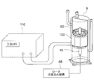
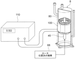
- FIG. 14 is a diagram showing a method of measuring the inductance of the coil 2.
- a measuring device 110 called an LCZ meter is used to measure the inductance of the coil 2 .
- An LCZ meter is an instrument that measures inductance (L), capacitance (C) and impedance (Z), and is sometimes called an LCR meter.
- the operator When measuring the inductance of the coil 2, the operator connects the measuring device 110 with the two terminals of the coil 2U. Although the inductance of the coil 2U is measured here, the inductance of the coil 2V or the coil 2W may be measured.
- the measuring device 110 applies a voltage of 1 [V] to the coil 2U to cause a minute current to flow through the coil 2U and measure the inductance of the coil 2U.
- the minute current is, for example, about 1/1000 of the magnetizing current that flows through the coil 2U when the permanent magnet 40 is magnetized.
- the operator After measuring the inductance [mH] of the coil 2U with the measuring device 110, the operator inputs the measured inductance to the voltage determining section 70 (FIG. 7).
- the voltage determining unit 70 and the measuring device 110 are connected so that the voltage determining unit 70 automatically acquires the inductance measurement result from the measuring device 110. good too.
- the voltage determining unit 70 calculates the optimum magnetizing voltage based on the inductance of the coil 2U and determines the magnetizing voltage. As a result, the magnetizing voltage can be increased when the rotation angle deviation of the rotor 3 is large, and can be decreased when the rotation angle deviation of the rotor 3 is small. That is, by adjusting the magnetizing voltage according to the deviation of the rotational angle of the rotor 3, the permanent magnet 40 can be uniformly magnetized.
- Machine learning includes supervised learning and unsupervised learning, and supervised learning is used here.
- the voltage determination unit 70 determines the inductance of the coil 2U measured before the second magnetization step, the magnetization voltage actually applied in the second magnetization step, and the Machine learning is performed using the magnetic flux linkage of the coil 2U measured after the magnetization step 2 as teacher data to generate a learned model.
- the inductance of the coil 2U corresponds to the rotation angle ⁇ of the rotor 3 in the second magnetization process (see FIG. 13).
- the magnetizing voltage is the magnetizing voltage actually applied in the second magnetizing step.
- the interlinking magnetic flux of the coil 2U corresponds to the magnetic force of the permanent magnet 40 after being magnetized.
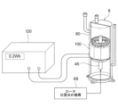
- FIG. 16 is a schematic diagram for explaining a method of measuring interlinkage magnetic flux.
- the flux linkage is measured after the second magnetization step of permanent magnet 40 .
- a measurement device 120 called a flux meter is used to measure the interlinkage magnetic flux.
- the operator When measuring the interlinkage magnetic flux, the operator connects the two terminals of the coil 2U to the measuring device 120. Although the magnetic flux linkage of the coil 2U is measured here, the magnetic flux linkage of the coil 2V or the coil 2W may be measured.
- No voltage is applied to the coil 2U when measuring the interlinkage magnetic flux.
- the rotor positioning mechanism 68 rotates the rotor 3
- the magnetic flux of the permanent magnets 40 interlinks with the coil 2U, causing current due to the induced electromotive force to flow through the coil 2U.
- the measuring device 120 measures the current flowing through the coil 2U and calculates the magnetic flux linkage.
- the rotation angle of the rotor 3 at this time is 120 degrees corresponding to two magnetic poles of the rotor 3 .
- the rotation angle of the rotor 3 is not limited to 120 degrees, and may be 360 degrees corresponding to six magnetic poles of the rotor 3, for example.
- the operator inputs the interlinkage magnetic flux measured by the measuring device 120 to the voltage determining section 70 (FIG. 7).
- the voltage determination unit 70 and the measurement device 120 may be connected so that the voltage determination unit 70 automatically acquires the measurement result of the interlinkage magnetic flux from the measurement device 120 .
- the voltage determination unit 70 determines the inductance of the coil 2U measured before the second magnetization process, the magnetization voltage applied in the second magnetization process, and the coil 2U measured after the second magnetization process.
- a trained model is generated by associating the magnetic flux linkages with each other.
- the inductance of the coil 2U is measured before the newly executed second magnetization step, and the measured inductance and the target value of the interlinkage magnetic flux are learned. Enter the model to determine the magnetizing voltage.
- the target value of the interlinkage magnetic flux is the value of the interlinkage magnetic flux required to obtain the magnetization ratio of the permanent magnet 40 of 99.7%, and is a constant value. Therefore, the target value of the interlinkage magnetic flux may be input by the operator, or may be stored in advance in the storage unit.
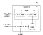
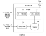
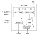
- FIG. 17 is a functional block diagram showing the voltage determining section 70.
- voltage determination section 70 includes learning section 71 , storage section 74 , and voltage calculation section 75 .
- the learning unit 71 has a data acquisition unit 72 that acquires data on the inductance, the magnetizing voltage, and the flux linkage, and a model generation unit 73 that generates a trained model based on the acquired data.
- the storage unit 74 stores the learned model generated by the model generation unit 73.
- the voltage calculator 75 uses the inductance of the coil 2 measured before the second magnetization step and the target value of the interlinkage magnetic flux as input data, as described with reference to FIG. A magnetizing voltage is calculated using the learned model generation unit 73 stored in the storage unit 74 .
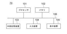
- FIG. 18 is a diagram showing an example of the hardware configuration of the voltage determining section 70. As shown in FIG. Each function of the voltage determining section 70 is realized by using a computer system such as a personal computer or a general-purpose computer.
- the voltage determination unit 70 has a processor 101 , a memory 102 , an external storage device 103 , an input device 104 and a display device 105 . These processor 101 , memory 102 , external storage device 103 , input device 104 and display device 105 are connected by bus 106 .
- the processor 101 is, for example, a CPU (Central Processing Unit).
- the function of the voltage determination unit 70 is implemented by the processor 101, software, firmware, or a combination of software and firmware.
- Software or firmware is written as a program and stored in the external storage device 103 .
- the processor 101 reads software or firmware stored in the external storage device 103 into the memory 102 and executes it.
- the memory 102 is RAM (Random Access Memory), ROM (Read Only Memory), flash memory, or the like.
- the external storage device 103 is a HDD (Hard Disk Drive) or SSD (Solid State Drive), or a cloud server.
- the input device 104 is, for example, a keyboard, a mouse or a touch panel, and inputs information to the voltage determining section 70 .
- the display device 105 is, for example, a display.
- the functions of the data acquisition unit 72 and the model generation unit 73 of the learning unit 71 shown in FIG. 17 can be realized by the processor 101 and the memory 102.
- the function of the storage unit 74 can be realized by the external storage device 103 .
- the function of the voltage calculator 75 can be realized by the processor 101, the memory 102, the input device 104, and the display device 105. For example, the operator inputs the input data using the input device 104 while viewing the display on the display device 105 .
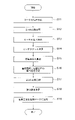
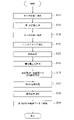
- FIG. 19 is a flowchart showing the magnetization method of Embodiment 1.
- FIG. 5 the rotor 3 having the permanent magnets 40 before magnetization is incorporated into the stator 1 to form the electric motor 100 , and the electric motor 100 is incorporated into the compressor 8 .
- the wires L1 and L2 of the magnetizing power source 60 are connected to the coils 2U, 2V and 2W of the electric motor 100 as shown in FIG. 11(A).
- the rotor positioning mechanism 68 rotates the rotor 3 from the reference position by the angle ⁇ in the first direction (step S11).
- the angle ⁇ between the d-axis of the rotor 3 and the center line T of the magnetizing magnetic flux is, for example, 5 to 10 degrees.
- the first magnetization step is executed (step S12). That is, a magnetizing voltage is applied from the magnetizing power supply 60 to the coils 2U, 2V and 2W.
- the magnetizing voltage is a predetermined voltage value.
- the rotor positioning mechanism 68 rotates the rotor 3 by the angle 2 ⁇ in the second direction (step S13).
- the angle ⁇ between the d-axis of the rotor 3 and the magnetizing magnetic flux center line T is the same as the angle ⁇ in the first magnetizing step.
- the measuring device 110 (FIG. 6A) is connected to the coil 2U to measure the inductance of the coil 2U (step S14).
- the operator inputs the measured inductance and the target value of the interlinkage magnetic flux into the voltage determination unit 70 .
- the measuring device 110 is removed from the coil 2U, and the wires L1 and L2 of the magnetizing power source 60 are connected to the coils 2U, 2V and 2W.
- the voltage determining unit 70 When receiving the input of the inductance and the interlinkage magnetic flux in step S14, the voltage determining unit 70 inputs these input data to the learned model and calculates the magnetizing voltage (step S15).
- the voltage determining unit 70 sets the magnetizing voltage of the magnetizing power supply 60 to the magnetizing voltage calculated in step S15 (step S16).
- step S17 a second magnetization step is executed (step S17). That is, the magnetizing voltage set in step S16 is applied from the magnetizing power supply 60 to the coils 2U, 2V, and 2W. As a result, magnetizing currents flow through the coils 2U, 2V, and 2W, and magnetizing magnetic fluxes are generated to magnetize the permanent magnets 40.
- FIG. 1 the magnetizing voltage set in step S16 is applied from the magnetizing power supply 60 to the coils 2U, 2V, and 2W.
- the measuring device 120 (Fig. 14) is connected to the coil 2U to measure the interlinkage magnetic flux (step S18).
- the operator inputs the measured interlinkage magnetic flux to the voltage determining section 70 .
- the voltage determination unit 70 adds the inductance measured in step S14, the magnetizing voltage applied in step S17, and the interlinkage magnetic flux measured in step S18 to the teacher data (step S19). .
- the magnetization process of the permanent magnet 40 is completed.
- the inductance of the coil 2 corresponding to the rotation angle of the rotor 3 is measured before the second magnetizing step, and the magnetizing voltage is determined based on the measured inductance. . Therefore, the permanent magnet 40 can be magnetized with a magnetizing voltage corresponding to the deviation of the rotation angle of the rotor 3, and the permanent magnet 40 can be uniformly magnetized. Also, unlike the case where the magnetizing voltage is uniformly increased, damage to the coils 2 due to the electromagnetic force acting on the coils 2 can be suppressed.
- the accuracy of calculating the magnetizing voltage is improved, thereby further improving the uniformity of the magnetization of the permanent magnet 40 .
- the more the magnetization process is repeated the more the number of teacher data increases, so the accuracy of calculating the magnetizing voltage is further improved.
- the learned model generated based on the teacher data acquired in the manufacturing test stage is stored in the storage unit 74 (FIG. 17). It shall be read and used.
- the permanent magnet 40 can be uniformly magnetized. is obtained.
- the magnetization voltage is applied to the coil 2 while the rotor 3 is rotated in the first direction by the angle ⁇ from the reference position. and a second magnetizing step of applying a magnetizing voltage to the coil 2 in a state in which the rotor 3 is rotated in the second direction from the reference position by an angle ⁇ , and before the second magnetizing step A magnetizing voltage for the second magnetizing step is determined based on the measured inductance of the coil 2 .
- the second magnetizing step it is possible to apply a magnetizing voltage corresponding to the deviation of the rotation angle of the rotor 3, and the permanent magnet 40 can be uniformly magnetized. Further, by performing the magnetizing process twice, the magnetizing voltage in one magnetizing process can be set low, so damage to the coil 2 can be suppressed.
- the inductance of the coil 2 measured before the past second magnetization step, the magnetizing voltage applied in the past second magnetization step, and the past second magnetization are learned.
- the magnetizing voltage is determined by inputting it into the finished model. Therefore, the magnetizing voltage can be determined more accurately, and the permanent magnet 40 can be magnetized more uniformly.
- Embodiment 2 Next, Embodiment 2 will be described.
- 20A and 20B are schematic diagrams for explaining the concept of machine learning according to the second embodiment.
- machine learning is performed using the resistance of the coil 2 as teacher data in addition to the inductance of the coil 2, the interlinkage magnetic flux of the coil 2, and the magnetizing voltage to generate a learned model.
- the resistance of the coil 2 is measured in addition to the inductance of the coil 2 before the second magnetization step. Then, as shown in FIG. 20A, the inductance and resistance of the coil 2, the magnetizing voltage applied in the second magnetizing step, and the interlinkage magnetic flux measured after the second magnetizing step are Perform machine learning as training data and generate a trained model.
- the inductance and resistance of the coil 2 are measured before the newly executed second magnetization process, and the measured inductance and resistance, the target value of the interlinkage magnetic flux, and is input to the trained model to calculate the magnetizing voltage.
- FIG. 21 is a diagram for explaining a method of measuring the resistance of the coil 2.
- the resistance of coil 2 is measured after the inductance measurement described in the first embodiment. However, the resistance of the coil 2 may be measured before measuring the inductance if it is before the second magnetization step.
- the measuring device 110 called the LCZ meter described above is used to measure the resistance of the coil 2. Since the operator connects the measuring device 110 to the two terminals of the coil 2U when measuring the inductance, the resistance of the coil 2 can be measured in that state. Although the resistance of the coil 2U is measured here, the resistance of the coil 2V or the coil 2W may be measured.
- a voltage is applied to the coil 2U to flow a current.
- the current at this time is equivalent to the current that flows through the coil 2U when measuring the inductance described in the first embodiment.
- the measuring device 110 measures the current flowing through the coil 2U and obtains the resistance [ ⁇ ] of the coil 2U.
- the operator inputs the measured resistance of the coil 2U to the voltage determining section 70.
- FIG. 22 is a functional block diagram showing the voltage determining section 70A of the second embodiment.
- the voltage determination unit 70A has a learning unit 71A, a storage unit 74, and a voltage calculation unit 75.
- the data acquisition unit 72 of the learning unit 71A acquires data on the inductance of the coil 2, the magnetizing voltage, the magnetic flux linkage of the coil 2, and the resistance of the coil 2.
- FIG. 22 is a functional block diagram showing the voltage determining section 70A of the second embodiment.
- the voltage determination unit 70A has a learning unit 71A, a storage unit 74, and a voltage calculation unit 75.
- the data acquisition unit 72 of the learning unit 71A acquires data on the inductance of the coil 2, the magnetizing voltage, the magnetic flux linkage of the coil 2, and the resistance of the coil 2.
- FIG. 22 is a functional block diagram showing the voltage determining section 70A of the second embodiment.
- the voltage determination unit 70A has a learning unit 71A, a storage unit 74, and
- the model generation unit 73 generates a learned model based on the data acquired by the data acquisition unit 72 .
- the storage unit 74 stores the learned model generated by the learning unit 71 .
- the voltage calculation unit 75 uses the inductance and resistance of the coil 2 measured before the second magnetization step and the target value of the interlinkage magnetic flux as input data, and the learned model generation unit 73 stored in the storage unit 74. to calculate the magnetizing voltage.
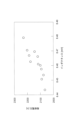
- FIG. 23 is a graph showing analysis results of the magnetizing voltage [V] when the rotation angle of the rotor 3, the inductance of the coil 2, and the resistance of the coil 2 are changed in multiple ways.
- the horizontal axis indicates the inductance [mH] of the coil 2
- the vertical axis indicates the magnetizing voltage [V] when the magnetization rate of the permanent magnet 40 reaches 99.7%.
- the magnetizing voltage can be determined using the inductance of the coil 2 as the first principal component and the resistance of the coil 2 as the second principal component.
- FIG. 24 is a flow chart showing the magnetization method of the second embodiment. Steps S11 to S14 in FIG. 24 are the same as in the first embodiment. After measuring the inductance of the coil 2U and inputting it to the voltage determining unit 70 in step S14, the operator connects the measuring device 110 to the coil 2U, measures the resistance, and inputs it to the voltage determining unit 70 (step S20). . After that, the measuring device 110 is removed from the coil 2U, and the magnetizing power source 60 is connected to the coils 2U, 2V and 2W.
- the voltage determining unit 70 uses the inductance and resistance of the coil 2U and the target value of the interlinking magnetic flux that were input in steps S14 and S20 as input data, and calculates the magnetizing voltage using the learned model (step S15). . Subsequent steps S16 to S18 are the same as in the first embodiment.
- step S19 the inductance measured in step S14, the resistance measured in step S20, the magnetizing voltage applied in step S17, and the flux linkage measured in step S18 are added to the teaching data.
- the magnetization process of the permanent magnet 40 is completed.
- inductance, resistance and magnetic flux linkage of coil 2U were measured in steps S14, S20 and S18, the inductance, resistance and magnetic flux linkage of coil 2V or coil 2W may be measured.
- the resistance of the coil 2 was measured in order to take into consideration the temperature rise of the coil 2 due to the current, but instead of measuring the resistance of the coil 2, the temperature of the coil 2 was measured by a temperature sensor such as a thermocouple. good too.
- the magnetizing voltage is determined based on the resistance of the coil 2 in addition to the inductance of the coil 2, the magnetizing voltage, and the interlinking magnetic flux of the coil 2. Therefore, the temperature rise of the rotor 3 is suppressed. Taking this into consideration, a more accurate magnetizing voltage can be calculated. Thereby, the permanent magnet 40 can be magnetized more uniformly.
- FIG. 25 is a functional block diagram showing voltage determining section 70B of the third embodiment.
- voltage determination unit 70B has learning unit 71, storage unit 74, and voltage calculation unit 75 described in the first embodiment, and further has upper limit setting unit 76.
- FIG. The upper limit setting section 76 is a section where the operator sets the upper limit of the magnetizing voltage calculated by the voltage calculating section 75 .
- the permanent magnets 40 have variations in manufacturing, there is a possibility that the smallest permanent magnets 40 within the range of dimensional tolerances will be incorporated into the rotor 3 . Such small-sized permanent magnets 40 tend to have a small interlinkage magnetic flux. Therefore, when the magnetizing voltage is calculated so that a desired magnetic flux interlinks with the small permanent magnet 40, the magnetizing voltage may become excessive.
- the upper limit setting unit 76 corrects the magnetizing voltage to the upper limit. That is, when calculating the magnetizing voltage in step S15 shown in FIG. 19, the magnetizing voltage is corrected so as not to exceed the upper limit.
- the upper limit setting unit 76 can be implemented by, for example, the processor 101, memory 102, input device 104, and display device 105 shown in FIG.
- the upper limit setting unit 76 is added to the voltage determining unit 70 described in the first embodiment, the upper limit setting unit 76 may be added to the voltage determining unit 70A (FIG. 22) described in the second embodiment. .
- the upper limit of the magnetizing voltage can be set when determining the magnetizing voltage in the second magnetizing step. It is possible to prevent the voltage from being applied. Thereby, damage to the coil 2 can be suppressed.
- FIG. 26 is a top view showing a modified stator 1A. All of the coils 2U, 2V, 2W of the stator 1A are arranged annularly around the axis Ax. The coil 2U is positioned radially innermost, the coil 2V is positioned radially outermost, and the coil 2W is positioned between the coils 2U and 2V in the radial direction.
- the coil 2U has six winding portions 20U arranged in the circumferential direction. Each winding portion 20U has two coil sides 21U that are inserted into slots 13 and two coil ends 22U that extend along the end surface of stator core 10 .
- the coil 2U is also referred to as a first phase (or inner layer) coil.
- the winding portion 20U is wound with a 3-slot pitch, in other words, so as to straddle three teeth 12 .
- Each one coil side 21U of two adjacent winding portions 20U is inserted into a common slot 13, and coil ends 22U extend from the slot 13 on both sides in the circumferential direction.
- the coil 2V has six winding portions 20V arranged in the circumferential direction. Each winding portion 20V has two coil sides 21V inserted into the slots 13 and two coil ends 22V extending along the end surface of the stator core 10 . Coil 2V is also referred to as a second phase (or outer layer) coil.
- the winding portion 20V is wound at a 3-slot pitch.
- One coil side 21V of each of two adjacent winding portions 20V is inserted into a common slot 13, and coil ends 22V extend from the slot 13 on both sides in the circumferential direction.
- the coil 2W has six winding portions 20W arranged in the circumferential direction. Each winding portion 20W has two coil sides 21W inserted into slots 13 and two coil ends 22W extending along the end surface of stator core 10 .
- the coil 2W is also referred to as a third phase (or middle layer) coil.
- the winding portion 20W is wound at a 3-slot pitch.
- Each one coil side 21W of two adjacent winding portions 20W is inserted into a common slot 13, and coil ends 22W extend from the slot 13 on both sides in the circumferential direction.
- the coil side 21W is inserted into the slot 13 counterclockwise adjacent to the slot 13 into which the coil side 21U is inserted.
- the coil side 21V is inserted in the slot 13 counterclockwise adjacent to the slot 13 in which the coil side 21W is inserted.
- FIG. 27 is a perspective view showing the stator 1A.
- Coil ends 22U, 22W and 22V are arranged on end faces 10a and 10b of the stator core 10 in the axial direction.
- the coil end 22W is positioned radially outside the coil end 22U, and the coil end 22V is positioned radially outside the coil end 22W.
- the stator core 10 has 18 slots 13, and each of the coils 2U, 2V, 2W has 6 winding portions 20. Therefore, the number of slots per winding pole is one. That is, three-phase coils 2U, 2V, and 2W are housed in three slots 13 for one magnetic pole.
- the number of winding portions 20 of each coil 2 is the same as the number of poles P. Moreover, the winding portion 20 is wound at a three-slot pitch.
- the magnetic pole pitch of the rotor 3 is 60 degrees in mechanical angle.
- the winding factor is 1 because the slot pitch and the magnetic pole pitch match.
- Each of two adjacent winding portions 20 of the coil 2 has one coil side 21 housed in a common slot 13, and coil ends 22 extend from the slot 13 on both sides in the circumferential direction.
- the number of the winding portions 20 of each coil 2 is half the number of poles P, as in the stator 1 shown in FIG. It is common to set it as three pieces. Since the slot pitch of the stator 1 is 60°, the winding coefficient is 1 and the magnetic flux of the permanent magnet 40 can be effectively used. However, since the number of the winding portions 20 of the coil 2 is three, each winding portion 20 is large, and the average circumference of the coil 2 is also long.
- the stator 1A has the same slot pitch and the coils 2 are distributed over the six winding portions 20. can do. Therefore, the average circumference of the coil 2 is shortened, and the winding resistance can be reduced. In addition, due to the reduction in winding resistance, the loss in the coil 2 is reduced and the efficiency of the electric motor 100 is improved.
- FIG. 28(A) is a diagram showing the connection state between the magnetizing power source 60 of the magnetizing device of the modified example and the coils 2U, 2W, and 2V.
- the coil 2W which is the middle layer coil
- the coil 2U which is the inner layer coil
- the coil 2V which is the outer layer coil
- This connection can be made, for example, with a glass terminal 309 shown in FIG.
- FIG. 28(B) is a schematic diagram showing the magnetizing current and the magnetizing magnetic flux in the first magnetizing step.
- magnetizing currents flow through the coils 2U and 2V, and no magnetizing current flows through the coil 2W.
- Magnetizing currents I in the same direction flow through winding portions 20U and 20V of coils 2U and 2V facing one permanent magnet 40 .
- a magnetizing magnetic flux is generated by the magnetizing current I and flows through the permanent magnet 40 .
- FIG. 28(C) is a schematic diagram showing the magnetizing current and the magnetizing magnetic flux in the second magnetizing step.
- magnetizing currents flow through the coils 2U and 2V and no magnetizing current flows through the coil 2W.
- Magnetizing currents I in the same direction flow through winding portions 20U and 20V of coils 2U and 2V facing one permanent magnet 40 .
- a magnetizing magnetic flux is generated by the magnetizing current I and flows through the permanent magnet 40 .
- the permanent magnet 40 forms an angle ⁇ (FIG. 10(A)) in the first direction with respect to the center line T of the magnetizing magnetic flux.
- the permanent magnet 40 forms an angle ⁇ (FIG. 10B) in the second direction with respect to the center line T of the magnetizing magnetic flux.
- the first region R1 of the permanent magnet 40 is magnetized, and in the second magnetizing step, the second region R2 of the permanent magnet 40 is magnetized.
- the magnetizing current causes the coils 2U, 2V and 2W to generate electromagnetic waves. It is possible to reduce the force and suppress damage to the coils 2U, 2V, 2W.
- FIG. 29 is a cross-sectional view showing compressor 300.
- Compressor 300 is compressor 8 shown in FIG.
- Compressor 300 is a scroll compressor here, but is not limited to this.
- the compressor 300 includes a shell 307, a compression mechanism 305 disposed within the shell 307, an electric motor 100 that drives the compression mechanism 305, a shaft 45 that connects the compression mechanism 305 and the electric motor 100, and a lower end of the shaft 45. and a subframe 308 that supports the part.
- the shell 307 corresponds to the shell 80 shown in FIG.
- the compression mechanism 305 includes a fixed scroll 301 having a spiral portion, an orbiting scroll 302 having a spiral portion forming a compression chamber between the spiral portion of the fixed scroll 301, and a compliance frame 303 holding the upper end of the shaft 45. and a guide frame 304 that is fixed to the shell 307 and holds the compliance frame 303 .
- a suction pipe 310 passing through the shell 307 is press-fitted into the fixed scroll 301 . Further, the shell 307 is provided with a discharge pipe 311 for discharging the high-pressure refrigerant gas discharged from the fixed scroll 301 to the outside.
- the discharge pipe 311 communicates with an opening (not shown) provided between the compression mechanism 305 of the shell 307 and the electric motor 100 .
- the electric motor 100 is fixed to the shell 307 by fitting the stator 1 into the shell 307 .
- the configuration of electric motor 100 is as described above.
- a glass terminal 309 for supplying electric power to the electric motor 100 is fixed to the shell 307 by welding.
- Wirings L1 and L2 shown in FIG. 6 are connected to a glass terminal 309 as a terminal portion.
- the electric motor 100 of the compressor 300 has stable electric motor efficiency and output with little variation because the permanent magnets 40 are uniformly magnetized. Therefore, the stability of the output of the compressor 300 can be improved.
- FIG. 30 is a diagram showing a refrigeration cycle device 400.
- the refrigeration cycle device 400 is, for example, an air conditioner, but is not limited to this.
- a refrigeration cycle device 400 shown in FIG. 30 includes a compressor 401, a condenser 402 that condenses refrigerant, a decompression device 403 that decompresses the refrigerant, and an evaporator 404 that evaporates the refrigerant.
- Compressor 401 , condenser 402 and decompression device 403 are provided in indoor unit 410
- evaporator 404 is provided in outdoor unit 420 .
- the compressor 401, the condenser 402, the decompression device 403 and the evaporator 404 are connected by a refrigerant pipe 407 to form a refrigerant circuit.
- Compressor 401 is composed of compressor 300 shown in FIG.
- the refrigerating cycle device 400 also includes an outdoor fan 405 facing the condenser 402 and an indoor fan 406 facing the evaporator 404 .
- the operation of the refrigeration cycle device 400 is as follows.
- the compressor 401 compresses the sucked refrigerant and sends it out as a high-temperature, high-pressure refrigerant gas.
- the condenser 402 exchanges heat between the refrigerant sent from the compressor 401 and the outdoor air sent by the outdoor fan 405, condenses the refrigerant, and sends it out as a liquid refrigerant.
- the decompression device 403 expands the liquid refrigerant sent from the condenser 402 and sends it out as a low-temperature, low-pressure liquid refrigerant.
- the evaporator 404 exchanges heat between the low-temperature, low-pressure liquid refrigerant sent out from the decompression device 403 and the indoor air, evaporates the refrigerant, and sends it out as refrigerant gas.
- the air from which heat has been removed by the evaporator 404 is supplied by the indoor blower 406 into the room, which is the space to be air-conditioned.
- the electric motor 100 described in each embodiment and modification can be applied to the compressor 401 of the refrigeration cycle device 400 . Since the permanent magnets 40 are uniformly magnetized, the electric motor 100 has stable electric motor efficiency and output with little variation. Therefore, the stability of the output of the refrigeration cycle device 400 can be improved.
Landscapes
- Engineering & Computer Science (AREA)
- Manufacturing & Machinery (AREA)
- Power Engineering (AREA)
- Permanent Field Magnets Of Synchronous Machinery (AREA)
Priority Applications (2)
| Application Number | Priority Date | Filing Date | Title |
|---|---|---|---|
| JP2023542071A JPWO2023021588A1 (cg-RX-API-DMAC7.html) | 2021-08-18 | 2021-08-18 | |
| PCT/JP2021/030096 WO2023021588A1 (ja) | 2021-08-18 | 2021-08-18 | 着磁方法、着磁装置、電動機、圧縮機および冷凍サイクル装置 |
Applications Claiming Priority (1)
| Application Number | Priority Date | Filing Date | Title |
|---|---|---|---|
| PCT/JP2021/030096 WO2023021588A1 (ja) | 2021-08-18 | 2021-08-18 | 着磁方法、着磁装置、電動機、圧縮機および冷凍サイクル装置 |
Publications (1)
| Publication Number | Publication Date |
|---|---|
| WO2023021588A1 true WO2023021588A1 (ja) | 2023-02-23 |
Family
ID=85240201
Family Applications (1)
| Application Number | Title | Priority Date | Filing Date |
|---|---|---|---|
| PCT/JP2021/030096 Ceased WO2023021588A1 (ja) | 2021-08-18 | 2021-08-18 | 着磁方法、着磁装置、電動機、圧縮機および冷凍サイクル装置 |
Country Status (2)
| Country | Link |
|---|---|
| JP (1) | JPWO2023021588A1 (cg-RX-API-DMAC7.html) |
| WO (1) | WO2023021588A1 (cg-RX-API-DMAC7.html) |
Citations (6)
| Publication number | Priority date | Publication date | Assignee | Title |
|---|---|---|---|---|
| JPH11243671A (ja) * | 1998-02-23 | 1999-09-07 | Daikin Ind Ltd | 永久磁石型電動機の着磁方法 |
| JP2005210882A (ja) * | 2003-12-26 | 2005-08-04 | Matsushita Electric Ind Co Ltd | 永久磁石型電動機の着磁方法および装置 |
| JP2017069435A (ja) * | 2015-09-30 | 2017-04-06 | ファナック株式会社 | 機械学習装置及び電動機用着磁装置 |
| WO2017130309A1 (ja) * | 2016-01-27 | 2017-08-03 | 三菱電機株式会社 | 着磁方法、回転子、電動機およびスクロール圧縮機 |
| WO2017130310A1 (ja) * | 2016-01-27 | 2017-08-03 | 三菱電機株式会社 | 回転子、着磁方法、電動機およびスクロール圧縮機 |
| WO2020240617A1 (ja) * | 2019-05-24 | 2020-12-03 | 三菱電機株式会社 | 電動機の製造方法、電動機、圧縮機、及び空気調和機 |
-
2021
- 2021-08-18 JP JP2023542071A patent/JPWO2023021588A1/ja not_active Withdrawn
- 2021-08-18 WO PCT/JP2021/030096 patent/WO2023021588A1/ja not_active Ceased
Patent Citations (6)
| Publication number | Priority date | Publication date | Assignee | Title |
|---|---|---|---|---|
| JPH11243671A (ja) * | 1998-02-23 | 1999-09-07 | Daikin Ind Ltd | 永久磁石型電動機の着磁方法 |
| JP2005210882A (ja) * | 2003-12-26 | 2005-08-04 | Matsushita Electric Ind Co Ltd | 永久磁石型電動機の着磁方法および装置 |
| JP2017069435A (ja) * | 2015-09-30 | 2017-04-06 | ファナック株式会社 | 機械学習装置及び電動機用着磁装置 |
| WO2017130309A1 (ja) * | 2016-01-27 | 2017-08-03 | 三菱電機株式会社 | 着磁方法、回転子、電動機およびスクロール圧縮機 |
| WO2017130310A1 (ja) * | 2016-01-27 | 2017-08-03 | 三菱電機株式会社 | 回転子、着磁方法、電動機およびスクロール圧縮機 |
| WO2020240617A1 (ja) * | 2019-05-24 | 2020-12-03 | 三菱電機株式会社 | 電動機の製造方法、電動機、圧縮機、及び空気調和機 |
Also Published As
| Publication number | Publication date |
|---|---|
| JPWO2023021588A1 (cg-RX-API-DMAC7.html) | 2023-02-23 |
Similar Documents
| Publication | Publication Date | Title |
|---|---|---|
| Hwang et al. | Design and analysis of a brushless DC motor for applications in robotics | |
| EP2372871A2 (en) | Permanent magnet motor | |
| Tsai et al. | Design of a miniature axial-flux spindle motor with rhomboidal PCB winding | |
| JP3828015B2 (ja) | 永久磁石形モータ及び永久磁石形モータの製造方法及び圧縮機及び冷凍サイクル装置 | |
| JP2003061283A (ja) | 回転電機の回転子、固定子、電動機、圧縮機、冷凍サイクル、回転電機の回転子製造方法 | |
| JP6779304B2 (ja) | ステータ、電動機、駆動装置、圧縮機、及び冷凍空調装置、並びにステータの製造方法 | |
| JP7058802B2 (ja) | 電動機の製造方法、電動機、圧縮機、及び空気調和機 | |
| US11888370B2 (en) | Stator, motor, compressor, air conditioner, and manufacturing method of stator | |
| WO2023032134A1 (ja) | 電動機、圧縮機および冷凍サイクル装置 | |
| US20230208232A1 (en) | Stator, electric motor, compressor, and air conditioner | |
| JPWO2021009862A1 (ja) | ステータ、モータ、圧縮機、及び空気調和機 | |
| WO2014065102A1 (ja) | 永久磁石同期機及びこれを用いた駆動システム、圧縮機 | |
| JPH09182388A (ja) | 永久磁石型電動機の着磁方法 | |
| WO2022054219A1 (ja) | 固定子、電動機、圧縮機、空気調和機、及び固定子の製造方法 | |
| Gurbhej et al. | Design of Highly Efficient Switched Reluctance Motor for Heavy Duty Exhaust Fan for Air Ventilation System | |
| JP7353508B2 (ja) | 固定子、電動機、圧縮機および空気調和装置 | |
| CN109417320A (zh) | 转子、电动机、送风机、压缩机以及空气调节装置 | |
| JP6537716B2 (ja) | 電動機駆動装置、電動機及び空気調和機 | |
| JP7486911B2 (ja) | 電動機、圧縮機、冷凍サイクル装置、着磁方法および着磁装置 | |
| WO2023084676A1 (ja) | リラクタンスモータ、圧縮機、空気調和装置、及びリラクタンスモータの製造方法 | |
| JP7237159B2 (ja) | 固定子、電動機、圧縮機、空気調和機、固定子の製造方法、及び着磁方法 | |
| JP2006034100A (ja) | 永久磁石形モータ | |
| JPH11243671A (ja) | 永久磁石型電動機の着磁方法 | |
| US11283379B2 (en) | Method and apparatus for detecting rotor magnetic pole position in a single-phase BLDC motor | |
| Karimi et al. | Cogging Torque Reduction of a BLDC Motor used for Evaporative Water Coolers |
Legal Events
| Date | Code | Title | Description |
|---|---|---|---|
| 121 | Ep: the epo has been informed by wipo that ep was designated in this application |
Ref document number: 21954162 Country of ref document: EP Kind code of ref document: A1 |
|
| WWE | Wipo information: entry into national phase |
Ref document number: 2023542071 Country of ref document: JP |
|
| NENP | Non-entry into the national phase |
Ref country code: DE |
|
| 122 | Ep: pct application non-entry in european phase |
Ref document number: 21954162 Country of ref document: EP Kind code of ref document: A1 |